EP3113151A1 - Convergence-supporting device, convergence-supporting method, and convergence-supporting program - Google Patents
Convergence-supporting device, convergence-supporting method, and convergence-supporting program Download PDFInfo
- Publication number
- EP3113151A1 EP3113151A1 EP14883923.6A EP14883923A EP3113151A1 EP 3113151 A1 EP3113151 A1 EP 3113151A1 EP 14883923 A EP14883923 A EP 14883923A EP 3113151 A1 EP3113151 A1 EP 3113151A1
- Authority
- EP
- European Patent Office
- Prior art keywords
- merging
- vehicle
- lane
- driver
- target vehicle
- Prior art date
- Legal status (The legal status is an assumption and is not a legal conclusion. Google has not performed a legal analysis and makes no representation as to the accuracy of the status listed.)
- Withdrawn
Links
- 238000000034 method Methods 0.000 title claims description 39
- 230000001133 acceleration Effects 0.000 description 6
- 238000004891 communication Methods 0.000 description 5
- 238000013500 data storage Methods 0.000 description 5
- 238000005259 measurement Methods 0.000 description 5
- 238000010586 diagram Methods 0.000 description 4
- 230000006870 function Effects 0.000 description 4
- 238000001514 detection method Methods 0.000 description 3
- 230000004044 response Effects 0.000 description 3
- 239000004973 liquid crystal related substance Substances 0.000 description 2
- 238000006243 chemical reaction Methods 0.000 description 1
- 238000004040 coloring Methods 0.000 description 1
- 238000009499 grossing Methods 0.000 description 1
- 238000003384 imaging method Methods 0.000 description 1
Images






Classifications
-
- G—PHYSICS
- G08—SIGNALLING
- G08G—TRAFFIC CONTROL SYSTEMS
- G08G1/00—Traffic control systems for road vehicles
- G08G1/16—Anti-collision systems
- G08G1/167—Driving aids for lane monitoring, lane changing, e.g. blind spot detection
Definitions
- the present invention relates to driving support technique for a vehicle at the time of merging.
- Patent Reference 1 discloses a method in which, when a merging vehicle indicates intention of merging and a vehicle running on the main lane permits or allows the merging, it is notified to a driver of the merging vehicle.
- Patent Reference 1 Japanese Patent Application Laid-open under No. 2012-118870
- Patent Reference 1 does not disclose anything about a merging place on the merging lane.
- the technique of Patent Reference 1 when executed, when a vehicle merges to a congested road for example, merging occurs at many positions on the merging lane and the main lane, resulting in further traffic congestion.
- the merging occurs at many positions, the vehicle running on the main lane may become necessary to accept merging of many vehicles inconveniently or unfairly.
- One invention described in claims is a merging support device comprising: a current position acquiring means which acquires a current position of a movable body; and a presentation control means which performs control of presenting a recommended merging area on a merging lane where merging is recommended, when the current position is on the merging lane for merging to a specific road.
- Another invention described in claims is a merging support method executed by a merging support device comprising: a current position acquiring process which acquires a current position of a movable body; and a presenting process which performs control of presenting a recommended merging area on a merging lane where merging is recommended, when the current position is on the merging lane for merging to a specific road.
- Still another invention described in claims is a merging support program executed by a merging support device including a computer, the programmaking the computer to function as : a current position acquiring means which acquires a current position of a movable body; and a presentation control means which performs control of presenting a recommended merging area on a merging lane where merging is recommended, when the current position is on the merging lane for merging to a specific road.
- a merging support device comprising: a current position acquiring means which acquires a current position of a movable body; and a presentation control means which performs control of presenting a recommended merging area on a merging lane where merging is recommended, when the current position is on the merging lane for merging to a specific road.
- the above merging support device is loaded on a movable body and acquires a current position of the movable body.
- the merging support device presents the recommended merging area when the movable body is on the merging lane.
- the recommended merging area is an area on the merging lane where merging is recommended, and is preferably an area of a predetermined distance from an ending position of the merging lane.
- the presentation control means performs control of presenting information prompting to start merging operation when the current position is in the recommended merging area.
- information prompting to start the merging operation e.g., an instruction to output the turn signal is presented.
- Another mode of the above merging support device further comprises a traffic congestion determining means which determines whether or not the merging lane is congested, wherein the presentation control means performs control of presenting the recommended merging area when the merging lane is determined to be congested.
- the recommended merging area is presented when the merging lane is congested.
- Still another mode of the above merging support device further comprises a designating unit which designates one other movable body running on the specific road as a target movable body, wherein the presentation control means performs control of presenting the information prompting to start the merging operation to merge behind the target movable body when the target movable body has been designated and the current position is in the recommended merging area.
- a movable body running on the specific road subjected to the merging is designated as the target movable body. Then, when the movable body enters the recommended merging area, information to merge behind the target movable body is presented.
- a merging support method executed by a merging support device comprising: a current position acquiring process which acquires a current position of a movable body; and a presenting process which performs control of presenting a recommended merging area on a merging lane where merging is recommended, when the current position is on the merging lane for merging to a specific road.
- a merging support program executed by a merging support device including a computer, the programmaking the computer to function as: a current position acquiring means which acquires a current position of a movable body; and a presentation control means which performs control of presenting a recommended merging area on a merging lane where merging is recommended, when the current position is on the merging lane for merging to a specific road.
- FIG. 1 illustrates a schematic configuration of a merging support device according to an embodiment of the present invention.
- the merging support device 100 is installed in a vehicle, and includes a navigation device 1, a front image sensor 15F, a side image sensor 15S, a rear image sensor 15R, a front radar 16F, a side radar 16S and a rear radar 16R.
- a navigation device 1 a front image sensor 15F, a side image sensor 15S, a rear image sensor 15R, a front radar 16F, a side radar 16S and a rear radar 16R.
- the front image sensor 15F, the side image sensor 15S and the rear image sensor 15R will be referred to as "the image sensor 15”
- the front radar 16F, the side radar 16S and the rear radar 16R will be referred to as "the radar 16s”.
- the image sensor 15 includes an imaging device such as a camera, and captures images around the vehicle. As shown in FIG. 2 , a pair of front image sensors 15F is mounted on the left and right positions of the front part of the vehicle 4, and each of the front sensors 15F captures the images of the range 17F. A pair of side image sensors 15S is mounted on the left and right positions of the side parts of the vehicle 4, and each of the side sensors 15S captures the images of the range 17S. A pair of rear image sensors 15R is mounted on the left and right positions of the rear part of the vehicle 4, and each of the rear sensors 15R captures the images of the range 17R. The detection results of the image sensors 15 are supplied to the navigation device 1.
- a pair of front image sensors 15F is mounted on the left and right positions of the front part of the vehicle 4, and each of the front sensors 15F captures the images of the range 17F.
- a pair of side image sensors 15S is mounted on the left and right positions of the side parts of the vehicle 4, and each of the side sensors 15S captures the
- the radar 16 may be a millimeter wave radar for example, and detects presence/absence of obstacles around the vehicle, the distance to the obstacle and the direction of the obstacle.
- a pair of front radars 16F is mounted on the left and right positions of the front part of the vehicle 4, and each of the front radars 16F detects the obstacles in the range 17F.
- a pair of side radars 16S is mounted on the left and right positions of the side parts of the vehicle 4, and each of the side radars 16S detects the obstacles in the range 17S.
- a pair of rear radars 16R is mounted on the left and right positions of the rear part of the vehicle 4, and each of the rear radars 16R detects the obstacles in the range 17R. The detection results of the radars 16 are supplied to the navigation device 1.
- FIG. 3 illustrates a configuration of the navigation device 1.
- the navigation device 1 includes a stand-alone position measurement device 10, a GPS receiver 18, a system controller 20, a disc drive 31, a data storage unit 36, a communication interface 37, a communication device 38, a display unit 40, a sound output unit 50 and an input device 60.
- the stand-alone position measurement device 10 includes an acceleration sensor 11, an angular velocity sensor 12 and a distance sensor 13.
- the acceleration sensor 11 includes a piezoelectric element, for example, and detects the acceleration degree of the vehicle and outputs the acceleration data.
- the angular velocity sensor 12 includes a vibration gyroscope, for example, and detects the angular velocity of the vehicle at the time of changing the direction of the vehicle and outputs the angular velocity data and the relative direction data.
- the distance sensor 13 measures vehicle speed pulses including pulse signals generated by the wheel revolution of the vehicle.
- the GPS receiver 18 receives an electric wave 19 for transmitting downlink data including position measurement data from plural GPS satellites.
- the position measurement data is used for detecting the absolute position (hereinafter referred to as "a current position") of the vehicle from longitude and latitude information.
- the system controller 20 includes an interface 21, a CPU 22, a ROM (Read Only Memory) 23 and a RAM (Random Access Memory) 24, and controls the entire navigation device 1.
- the interface 21 executes the interface operation with the acceleration sensor 11, the angular velocity sensor 12, the distance sensor 13 and the GPS receiver 18. Then, the interface 21 inputs the vehicle speed pulse, the acceleration data, the relative direction data, the angular velocity data, the GPS measurement data and the absolute direction data into the system controller 20. In addition, the interface 21 executes the interface operation with the image sensors 15 and the radars 16, and inputs the images captured by the image sensors 15 and the detection signals generated by the radars 16 to the systemcontroller 20.
- the CPU 22 controls the entire system controller 20.
- the ROM 23 includes a non-volatile memory (not shown) in which a control program for controlling the system controller 20 is stored.
- the RAM 24 readably stores various kinds of data such as route data preset by the user via the input device 60, and provides a working area to the CPU 22.
- the system controller 20, the disc drive 31 such as a CD-ROM drive or a DVD-ROM drive, the data storage unit 36, the communication interface 37, the display unit 40, the sound output unit 50 and the input device 60 are connected with each other via a bus line 30.
- the disc drive 31 reads contents data such as sound data and picture data from the disc 33 such as a CD and a DVD to output the contents data.
- the data storage unit 36 includes HDD, for example, and stores various kinds of data used for a navigation process such as map data.
- the communication device 38 acquires vehicle information 39 managed by an ECU (Electronic Control Unit) via an in-vehicle communication network.
- ECU Electronic Control Unit
- the display unit 40 displays various kinds of display data on a display device such as a display under the control of the systemcontroller20. Specifically,thesystem controller20reads the map data from the data storage unit 36. The display unit 40 displays, on a display screen such as a display, the map data read from the data storage unit 36 by the system controller 20.
- the display unit 40 includes a graphic controller 41 for controlling the entire display unit 40 on the basis of the control data transmitted from the CPU 22 via the bus line 30, a buffer memory 42 for temporarily storing image information having a memory such as a VRAM (Video RAM) and immediately displayable, a display control unit 43 for controlling a display 44 such as a liquid crystal and a CRT (Cathode Ray Tube) on the basis of the image data outputted from the graphic controller 41, and the display 44.
- the display 44 is formed by a liquid crystal display device of the opposite angle 5-10 inches, and is mounted in the vicinity of a front panel of the vehicle.
- the sound output unit 50 includes a D/A converter 51 for executing D/A conversion of the sound digital data transmitted from the disc drive 31 or the RAM 24 via the bus line 30 under the control of the system controller 20, an amplifier (AMP) 52 for amplifying an audio analog signal outputted from the D/A converter 51, and a speaker 53 for converting the amplified audio analog signal into the sound and outputting it to the vehicle compartment.
- a D/A converter 51 for executing D/A conversion of the sound digital data transmitted from the disc drive 31 or the RAM 24 via the bus line 30 under the control of the system controller 20
- AMP amplifier
- speaker 53 for converting the amplified audio analog signal into the sound and outputting it to the vehicle compartment.
- the input device 60 includes keys, switches, buttons, a remote controller and a speech input device, which are used for inputting various kinds of commands and data.
- the input device 60 is arranged in the vicinity of a front panel of a main body and the display 44 of an on-vehicle electric system installed in the vehicle. Additionally, in such a case that the display 44 is of a touch panel system, a touch panel provided on the display screen of the display 44 functions as the input device 60, too.
- the CPU 22 functions as the current position acquiring means, the presentation control means and the traffic congestion determining means.
- the merging support method of the embodiment is characterized by first setting a recommended merging area (hereinafter referred to as "the merging zone”), where it is recommended to start the merging operation of the movable body to the main lane, near the point where the merging lane ends, during traffic congestion.
- FIGS. 4A and 4B are diagrams for explaining the merging support method of the embodiment. Specifically, FIG. 4A schematically illustrates the situation that a driver' s vehicle 4 is going to merge from the merging lane to the main lane when the merging place is congested.
- “the merging place” indicates an area on the main lane and the merging lane where the merging lane is provided along the main lane and the vehicle can change the lane.
- the recommended merging area (the merging zone) indicates the ending position of the merging lane in the merging place, i.e., an area of a predetermined distance (length) from the ending point of the merging lane.
- plural vehicles 5 exist ahead of the vehicle 4 on the merging lane. Also, the main lane is congested, and plural vehicles 5 exist in line.
- the merging place is congested like this, if the plural vehicles on the merging lane try to merge to the main lane at different positions respectively, the merging operation occurs at plural positions. As a result, smooth merging becomes difficult, and the congestion of the main lane may get worse.
- the merging support device 100 sets the merging zone 7 of a predetermined distance at the ending position of the merging lane, i.e., the point near the ending point of the merging lane, and present it to the driver to guide the driver to merge to the main lane at the merging zone 7.
- the merging support device 100 selects the vehicle 5, which is presumed to exist on the main lane at the position neighboring the driver's vehicle 4 when the driver's vehicle 4 enters the merging zone 7, as a target vehicle 5T, and performs the merging guidance utilizing the target vehicle 5T as a mark. Namely, the merging support device 100 guides the driver to merge to the main lane at the position behind the target vehicle 5T when the driver's vehicle 4 enters the merging zone 7. Specifically, when the driver's vehicle 4 is running on the merging lane as shown in FIG. 4A , the merging support device 100 selects the vehicle 5, which is existing on the main lane and neighboring the driver's vehicle 4, as the target vehicle 5T.
- the merging support device 100 guides the driver to merge to the main lane at the position behind the target vehicle 5T.
- the merging support device 100 guides the driver to merge to the main lane at the position behind the target vehicle 5T.
- the merging support device 100 changes the target vehicle 5T as necessary until the driver's vehicle 4 enters the merging zone 7. Namely, if the speeds of the vehicle flow on the merging lane and the main lane are different and it is presumed that the current target vehicle 5T will move away from the driver' s vehicle 4 when the driver's vehicle 4 actually enters the merging zone 7, the merging support device 100 changes to the target vehicle 5T to one other vehicle ahead of or behind the current target vehicle 5T. Thereby, it becomes possible to perform the merging guidance using the target vehicle 5T of the appropriate position as the target when the driver's vehicle 4 actually enters the merging zone 7.
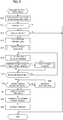
- FIG. 5 is a flowchart of the merging support processing. This merging support processing is achieved by the CPU 22 of the navigation device 1 constituting the merging support device 100 which executes program prepared in advance.
- the navigation device 1 confirms the road situation in the travelling direction (step S10). Specifically, the navigation device 1 acquires information such as a current position of the vehicle, a speed of the vehicle, map data, traffic information, a speed of the vehicle running ahead captured by the front image sensor 15F and the front radar 16F, and road signs (signboard).
- information such as a current position of the vehicle, a speed of the vehicle, map data, traffic information, a speed of the vehicle running ahead captured by the front image sensor 15F and the front radar 16F, and road signs (signboard).
- the navigation device 1 determines whether or not the road on which the driver's vehicle 4 is running is congested, based on the speed of the vehicle, the traffic information, the images captured by the front image sensor 15F and the result of detecting the obstacles by the front radar 16F (step S11).
- the navigation device ends the processing.
- step S11 when the running road is congested (step S11: Yes), the navigation device 1 determines whether or not the lane the driver's vehicle 4 is currently running is going to reduce, i.e., the lane currently running is the merging lane (step S12). When the lane is not going to reduce (step S12 : No), the lane currently running is not the merging lane, and the navigation device 1 ends the processing.
- the navigation device 1 sets the merging zone 7, and presents it to the driver (step S13). Specifically, the navigation device 1 sets the area of the predetermined distance (length) from the ending position of the currently running merging lane to the merging zone 7. Basically, the length of the merging zone 7 maybe determined in advance as the distance that is necessary for one vehicle of regular size to merge to the main lane.
- the flow of the vehicles on the merging lane i.e., the speed of the vehicles running on the merging lane may be estimated based on the speed of the driver' s vehicle 4, and the length of the merging zone 7 may be changed in accordance with the estimated speed.
- the merging zone 7 may be long when the vehicle flow on the merging lane is fast, and the merging zone may be short when the vehicle flow on the merging lane is slow.
- the navigation device 1 presents the merging zone 7 to the driver by coloring the merging zone 7 on the map displayed on the display 44 and/or outputting the distance from the current position of the driver's vehicle 4 to the merging zone 7 by sound of voice. For example, the navigation device 1 outputs the voice announcement "Merge at the merging zone 100m ahead!.
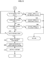
- FIG. 6 illustrates a flowchart of target vehicle selection processing.
- the navigation device 1 determines whether or not there is a vehicle neighboring the driver's vehicle 4 on the main lane based on the outputs from the side image sensor 15S and the side radar 16S (step S30). When there is no vehicle (step S30: No), the process goes to step S34. When there is a vehicle (step S30: Yes), the navigation device 1 determines whether or not the main lane includes two or more lanes based on the map data (step S31).
- step S31:No When the main lane does not include two or more lanes (step S31:No), the main lane includes one lane and there is a vehicle neighboring the driver's vehicle 4 on the main lane, and therefore the navigation device 1 selects the vehicle detected in step S30 as the target vehicle 5T (step S33). If plural vehicles are detected in step S30, the navigation device 1 selects the vehicle nearest to the driver's vehicle 4 as the target vehicle 5T.
- step S31 when the main lane include two or more lanes (step S31: Yes), the navigation device 1 determines whether or not the distance from the driver's vehicle 4 to the neighboring vehicle detected in step S30 is equal to or larger than one lane (step S32). When the distance to the detected vehicle is not equal to or larger than one lane (step S32: No), the detected vehicle is on the neighboring lane, and the navigation device 1 selects the detected vehicle as the target vehicle 5T (step S33).
- step S32: Yes when the distance to the detected vehicle is equal to or larger than one lane (step S32: Yes), the detected vehicle is not on the neighboring lane to which the driver' s vehicle 4 is going to merge. Therefore, the navigation device 1 does not select the detected vehicle as the target vehicle 5T, and the process goes to step S34.
- step S34 the navigation device 1 determines whether or not there are foregoing vehicles on the neighboring lane based on the outputs of the front image sensor 15F and the forward radar 16F.
- step S34 the navigation device 1 selects the nearest vehicle of the detected foregoing vehicles as the target vehicle 5T (step S35).
- step S34 when there is no foregoing vehicle on the neighboring lane (step S34 : No), the navigation device 1 determines whether or not there are following vehicles on the neighboring lane (step S36). When there are following vehicles on the neighboring lane (step S36: Yes), the navigation device selects the nearest vehicle of the detected following vehicle as the target vehicle 5T (step S37).
- step S36 determines whether or not the driver's vehicle 4 enters the merging zone 7 (step S38).
- step S38 determines whether or not the driver's vehicle 4 enters the merging zone 7 (step S38).
- step S38 Yes
- the navigation device 1 guides the driver to output the turn signal (step S39), checks the backward direction by the rear image sensor 15R and the rear radar 16R (step S40), and instructs the driver to merge (step S41).
- the driver performs merging, and the merging support processing ends.
- the target vehicle 5T is not selected, and the navigation device 1 performs the merging support without using the target vehicle 5T.
- step S15 the navigation device 1 detects the distance and the speed difference between the driver's vehicle 4 and the target vehicle 5T by the image sensor 15 and the radar 16). Specifically, the navigation device 1 can detect the distance between the driver's vehicle 4 and the target vehicle 5T by the radar 16. Also, the navigation device 1 can detects the speed difference between the driver's vehicle 4 and the target vehicle 5T by detecting the change of the relative positional relation between the driver's vehicle 4 and the target vehicle 5T by the image sensor 15 and the radar 16.
- the navigation device 1 can track the target vehicle 5T by detecting the color of the target vehicle 5T based on the output of the image sensor 15 and detecting the change of the distance to the target vehicle 5T based on the output of the radar 16. For example, the navigation device 1 can determine that the target vehicle 5T has gone away if the flow of the neighboring lane suddenly becomes fast and a vehicle of the color different from that of the target vehicle 5T comes out next to the driver's vehicle 4, or if the distance to the target vehicle 5T becomes far and other nearer vehicle is detected.
- the navigation device 1 determines whether or not the current target vehicle 5T coincides with the target vehicle 5T when the driver's vehicle 4 enters the merging zone 7 (hereinafter referred to as "the final target vehicle") based on the distance and the speed difference between the driver's vehicle 4 and the target vehicle 5T (step S16).
- the navigation device 1 calculates an expected distance between the driver's vehicle 4 and the target vehicle 5 when the driver's vehicle 4 enters the merging zone 7 based on the distance and the speed difference between the driver's vehicle 4 and the target vehicle 5T, and predicts whether or not there exists other vehicle nearer than the expected distance. Then, the navigation device 1 determines that the current target vehicle 5T does not coincide with the final target vehicle when it is predicted that there exists other vehicle nearer than the expected distance, and determines that the current target vehicle 5T coincides with the final target vehicle when it is predicted that there exists no vehicle nearer than the expected distance.
- the navigation device 1 calculates an expected distance between the driver's vehicle 4 and the target vehicle 5T when the driver's vehicle 4 enters the merging zone 7, and determines that the current target vehicle 5T does not coincide with the final target vehicle if the expected distance is longer than a predetermined distance. Since the merging support processing according to the embodiment is executed when the merging place is congested, there may exist other vehicles in front of and behind the current target vehicle 5T with a normal inter-vehicle distance.
- the navigation device 1 may presume that the vehicle in front of or behind the current target vehicle 5T becomes nearer to the driver' s vehicle 4 than the current target vehicle 5T, and may determine that the current target vehicle 5T does not coincide with the final target vehicle.
- step S17 When it is determined that the current target vehicle 5T does not coincide with the final target vehicle (step S16: No), the navigation device 1 executes the target vehicle changing processing (step S17).
- the target vehicle changing processing will be specifically described later.
- step S18 determines whether or not the driver's vehicle 4 has entered the merging zone 7 (step S18). When the driver's vehicle 4 has not entered the merging zone 7 (step S18: No), the process returns to step S15. Then, until the driver's vehicle 4 enters the merging zone 7, steps S15 to S17 are repeated to change the target vehicle 5T as necessary.
- the navigation device 1 determines whether or not the target vehicle 5T at that time (which will be the final target vehicle) exists at the side of the driver's vehicle 4 or ahead of the driver's vehicle 4 on the neighboring lane (step S19).
- step S19: No When the target vehicle 5T does not exist at the side of the driver's vehicle 4 or ahead of the driver's vehicle on the neighboring lane (step S19: No), the target vehicle 5T exists behind the driver's vehicle 4, and hence the navigation device 1 instructs the driver to decelerate the driver's vehicle 4 (step S20). Thus, the navigation device 1 performs the guidance such that the driver's vehicle 4 can merge behind the target vehicle 5T. Then, the process returns to step S19.
- the navigation device 1 guides the driver to output the turn signal to start the merging operation (step S21). Then, the navigation device 1 confirms that there is a predetermined space behind the target vehicle 5T, i. e., the vehicle immediately behind the target vehicle 5T has created a space from the target vehicle 5T to allow the merging of the driver's vehicle 4 in response to the output of the turn signal by the driver's vehicle 4 (step S22), and instructs the driver to merge (step S23) . In response, the driver merges the driver's vehicle 4 to the main lane. Thus, the merging support processing ends.
- the vehicle flow on the main lane can be prioritized, and it is possible to prevent the traffic congestion at the merging place from getting worse.
- FIGS. 7 and 8 are flowcharts of the target vehicle changing processing.
- the navigation device 1 determines whether or not the target vehicle 5T has changed the lane based on the outputs from the image sensor 15 and the radar 16 (step S50). For example, when the distance to the target vehicle 5T becomes equal to or larger than one lane, the navigation device 1 can determine that the target vehicle 5T has changed the lane.
- the navigation device 1 determines whether or not the vehicle presumed to be neighboring the driver's vehicle 4 when the driver's vehicle 4 enters the merging zone 7 (hereinafter referred to as "presumed vehicle") is present on the main lane, based on the outputs of the image sensor 15 and the radar 16 (step S51).
- the navigation device 1 changes the target vehicle 5T to the presumed vehicle (step S52). Then, the process returns to the main routine of FIG. 5 .
- step S51 determines whether or not there is a vehicle between the current target vehicle 5T and the side position of the driver' s vehicle 4 when the driver' s vehicle 4 enters the merging zone 7 (step S53).
- step S53 determines whether or not there are a plurality of such vehicles (step S54).
- step S54 determines whether or not there are a plurality of such vehicles (step S54: No), i.e., such a vehicle is only one, the navigation device 1 changes the target vehicle 5T to that one vehicle. Then, the process returns to the main routine of FIG. 5 .
- step S54 when there are a plurality of such vehicle (step S54: Yes), the navigation device 1 changes the target vehicle 5T to the vehicle, out of those plurality of vehicles, nearest to the side position of the driver's vehicle 4 when the driver's vehicle 4 enters the merging zone 7 (step S56). Then, the process returns to the main routine of FIG. 5 .
- step S53 When there is no vehicle between the current target vehicle 5T and the side position of the driver' s vehicle 4 when the driver' s vehicle 4 enters the merging zone 7 (step S53: No), the navigation device 1 does not change the target vehicle 5T (step S57). Then, the process returns to the main routine of FIG. 5 .
- step S50 when the target vehicle has changed the lane (step S50: Yes), the navigation device 1 changes the target vehicle basically by the same method as the target vehicle changing processing shown in FIG. 6 . Namely, in FIG. 8 , first the navigation device 1 determines whether or not there is a vehicle neighboring the driver's vehicle 4 (step S61), and when there is a vehicle (step S61: Yes), the navigation device 1 changes the target vehicle 5T to the neighboring vehicle (step S62). Then, the process returns to the main routine of FIG. 5 .
- step S61 When there is no vehicle neighboring the driver's vehicle 4 (step S61: No), the navigation device 1 determines whether or not there is a foregoing vehicle on the neighboring lane (step S63), and when there is a vehicle (step S63: Yes), the navigation device 1 changes the target vehicle 5T to the foregoing vehicle (step S64). Then, the process returns to the main routine of FIG. 5 .
- step S63 When there is no foregoing vehicle on the neighboring lane (step S63: No), the navigation device 1 determines whether or not there is a following vehicle on the neighboring lane (step S65), and when there is a vehicle (step S65: Yes), the navigation device 1 changes the target vehicle 5T to the following vehicle on the neighboring lane (step S66). Then, the process returns to the main routine of FIG. 5 .
- step S65: No the navigation device 1 determines whether or not the driver's vehicle 4 has entered the merging zone 7 (step S67) .
- step S67: No the process returns to step S61, and steps S61 to S66 for searching the target vehicle are repeated until the driver's vehicle 4 enters the merging zone 7.
- the navigation device 1 performs the merging guidance without using the target vehicle 5T. Specifically, the navigation device 1 guides the driver to output the turn signal (step S68), checks the backward direction by the rear image sensor 15R and the rear radar 16R (step S69), and instructs the driver to merge (step S70). In response, the driver merges to the main lane, and the merging support processing ends.
- the target vehicle 5T is changed according to the flow of the driver's vehicle 4 and the vehicles on the main lane until the driver's vehicle 4 actually enters the merging zone 7. Thereby, the driver's vehicle 4 can merge behind the appropriate target vehicle 5T.
- FIGS. 9A to 9C show an example of changing the target vehicle when the driver's vehicle 4 is faster than the target vehicle 5T.
- FIG. 9A it is now assumed that the driver's vehicle 4 enters the merging lane and the vehicle 5d neighboring the driver' s vehicle 4 on the main lane is set to the target vehicle 5T.
- the navigation device 1 calculates the distance and the speed difference between the driver's vehicle 4 and the target vehicle 5T by the image sensor 15 and the radar 16. Also, the navigation device 1 calculates an estimated required time for the driver's vehicle 4 to enter the merging zone 7 and an estimated required time for the target vehicle 5T to enter the merging zone 7 based on the current position and speed of the driver's vehicle 4 and the distance to the merging zone 7. Now, it is estimated that the driver's vehicle 4 will enter the merging zone 7 in five seconds and the target vehicle 5T will reach the side of the merging zone 7 in ten seconds.
- the navigation device 1 regards the speed of the current target vehicle 5T as the speed of the vehicle flow on the main lane, and determines the vehicle 5c preceding the current target vehicle 5T (5d) by 5 seconds as the new target vehicle 5T as shown in FIG. 9B . Namely, the navigation device 1 changes the target vehicle 5T from the vehicle 5d to the vehicle 5c.
- the navigation device 1 performs the guidance to merge behind the target vehicle 5T (5c).
- the navigation device 1 determines, as the new target vehicle 5T, the vehicle that exists between the current target vehicle 5T and the position five seconds preceding the current target vehicle 5T and that is nearer to the position five seconds preceding the current target vehicle 5T. Also, if there is no vehicle between the current target vehicle 5T and the position five seconds preceding the current target vehicle 5T, the navigation device 1 does not change the target vehicle 5T and continues to use the current target vehicle 5T.
- FIGS. 10A to 10C show the example of changing the target vehicle when the driver's vehicle 4 is slower than the target vehicle 5T.
- FIG. 10A it is now assumed that the driver's vehicle 4 enters the merging lane 7 and the vehicle 5c neighboring the driver' s vehicle 4 on the main lane is set to the target vehicle 5T.
- the navigation device 1 calculates an estimated required time for the driver's vehicle 4 to enter the merging zone 7 and an estimated required time for the target vehicle 5T to enter the merging zone 7. Now, it is estimated that the driver's vehicle 4 will enter the merging zone 7 in ten seconds and the target vehicle 5T will reach the side of the merging zone 7 in five seconds. In this case, the navigation device 1 regards the speed of the current target vehicle 5T as the speed of the vehicle flow on the main lane, and determines the vehicle 5dbehind the current target vehicle 5T (5c) by 5 seconds as the new target vehicle 5T as shown in FIG. 10B . Namely, the navigation device 1 changes the target vehicle 5T from the vehicle 5c to the vehicle 5d.
- the navigation device 1 performs the guidance to merge behind the target vehicle 5T (5d).
- the navigation device 1 determines, as the new target vehicle 5T, the vehicle that exists between the current target vehicle 5T and the position five seconds behind the current target vehicle 5T and that is nearer to the position five seconds behind the current target vehicle 5T. Also, if there is no vehicle between the current target vehicle 5T and the position five seconds behind the current target vehicle 5T, the navigation device 1 does not change the target vehicle 5T and continues to use the current target vehicle 5T.
- the merging support device 100 presents the merging zone 7 when the merging lane is congested.
- the merging support device may also present the merging zone 7 when the merging lane is not congested.
- the merging support device 100 is constituted by the on-vehicle navigation device 1.
- the present invention may be applied to the case where the navigation device is constituted by a portable terminal such as a smartphone which executes navigation application.
- This invention can be used for an on-vehicle navigation device, and a navigation device of a portable terminal such as a smartphone.
Landscapes
- Physics & Mathematics (AREA)
- General Physics & Mathematics (AREA)
- Navigation (AREA)
- Traffic Control Systems (AREA)
Abstract

Description
- The present invention relates to driving support technique for a vehicle at the time of merging.
- There is proposed a car navigation device which supports driving at the time of merging from a merging lane to a main lane. For example,
Patent Reference 1 discloses a method in which, when a merging vehicle indicates intention of merging and a vehicle running on the main lane permits or allows the merging, it is notified to a driver of the merging vehicle. - Patent Reference 1: Japanese Patent Application Laid-open under No.
2012-118870 -
Patent Reference 1 does not disclose anything about a merging place on the merging lane. In addition, when the technique ofPatent Reference 1 is executed, when a vehicle merges to a congested road for example, merging occurs at many positions on the merging lane and the main lane, resulting in further traffic congestion. Furthermore, when the merging occurs at many positions, the vehicle running on the main lane may become necessary to accept merging of many vehicles inconveniently or unfairly. - The above are examples of problems to be solved by the present invention. It is an object of the present invention to provide a merging support device capable of smoothing the traffic flow at the merging place by concentrating the merging points to a single point at the time of traffic congestion.
- One invention described in claims is a merging support device comprising: a current position acquiring means which acquires a current position of a movable body; and a presentation control means which performs control of presenting a recommended merging area on a merging lane where merging is recommended, when the current position is on the merging lane for merging to a specific road.
- Another invention described in claims is a merging support method executed by a merging support device comprising: a current position acquiring process which acquires a current position of a movable body; and a presenting process which performs control of presenting a recommended merging area on a merging lane where merging is recommended, when the current position is on the merging lane for merging to a specific road.
- Still another invention described in claims is a merging support program executed by a merging support device including a computer, the programmaking the computer to function as : a current position acquiring means which acquires a current position of a movable body; and a presentation control means which performs control of presenting a recommended merging area on a merging lane where merging is recommended, when the current position is on the merging lane for merging to a specific road.
-
-
FIG. 1 is a block diagram illustrating a schematic configuration of a merging support device according to an embodiment of the present invention. -
FIG. 2 schematically illustrates recognition ranges of image sensors and radars. -
FIG. 3 is a block diagram illustrating a configuration of a navigation device. -
FIGS. 4A and 4B are diagrams for explaining a basic method of merging support. -
FIG. 5 is a flowchart of merging support processing. -
FIG. 6 is a flowchart of target vehicle selection processing. -
FIG. 7 is a flowchart of target vehicle changing processing. -
FIG. 8 is a flowchart of target vehicle changing processing. -
FIGS. 9A to 9C illustrate an example of changing the target vehicle. -
FIGS. 10A to 10C illustrates another example of changing the target vehicle. - According to one aspect of the present invention, there is provided a merging support device comprising: a current position acquiring means which acquires a current position of a movable body; and a presentation control means which performs control of presenting a recommended merging area on a merging lane where merging is recommended, when the current position is on the merging lane for merging to a specific road.
- The above merging support device is loaded on a movable body and acquires a current position of the movable body. The merging support device presents the recommended merging area when the movable body is on the merging lane. The recommended merging area is an area on the merging lane where merging is recommended, and is preferably an area of a predetermined distance from an ending position of the merging lane. By the merging support device, the recommended merging area is presented when the movable body is on the merging lane. Therefore, the movable bodies merge in the recommended merging area in order, and the congestion at the merging place can be prevented.
- In one mode of the above merging support device, the presentation control means performs control of presenting information prompting to start merging operation when the current position is in the recommended merging area. In this mode, when the current position of the movable body enters the recommended merging area, information prompting to start the merging operation, e.g., an instruction to output the turn signal is presented.
- Another mode of the above merging support device further comprises a traffic congestion determining means which determines whether or not the merging lane is congested, wherein the presentation control means performs control of presenting the recommended merging area when the merging lane is determined to be congested. In this mode, the recommended merging area is presented when the merging lane is congested.
- Still another mode of the above merging support device further comprises a designating unit which designates one other movable body running on the specific road as a target movable body, wherein the presentation control means performs control of presenting the information prompting to start the merging operation to merge behind the target movable body when the target movable body has been designated and the current position is in the recommended merging area. In this mode, a movable body running on the specific road subjected to the merging is designated as the target movable body. Then, when the movable body enters the recommended merging area, information to merge behind the target movable body is presented.
- According to another aspect of the present invention, there is provided a merging support method executed by a merging support device comprising: a current position acquiring process which acquires a current position of a movable body; and a presenting process which performs control of presenting a recommended merging area on a merging lane where merging is recommended, when the current position is on the merging lane for merging to a specific road. By this merging support method, the recommended merging area is presented when the movable body is on the merging lane.
- According to still another aspect of the present invention, there is provided a merging support program executed by a merging support device including a computer, the programmaking the computer to function as: a current position acquiring means which acquires a current position of a movable body; and a presentation control means which performs control of presenting a recommended merging area on a merging lane where merging is recommended, when the current position is on the merging lane for merging to a specific road. By executing the program by the computer, the above merging support device can be realized. This merging support programmaybe handled in a manner stored in a storage medium.
- A Preferred embodiment of the present invention will be described below with reference to the attached drawings.
-
FIG. 1 illustrates a schematic configuration of a merging support device according to an embodiment of the present invention. The mergingsupport device 100 is installed in a vehicle, and includes anavigation device 1, afront image sensor 15F, aside image sensor 15S, arear image sensor 15R, afront radar 16F, aside radar 16S and arear radar 16R. In the following description, when it is not necessary to discriminate the position, thefront image sensor 15F, theside image sensor 15S and therear image sensor 15R will be referred to as "theimage sensor 15", and thefront radar 16F, theside radar 16S and therear radar 16R will be referred to as "the radar 16s". - The
image sensor 15 includes an imaging device such as a camera, and captures images around the vehicle. As shown inFIG. 2 , a pair offront image sensors 15F is mounted on the left and right positions of the front part of thevehicle 4, and each of thefront sensors 15F captures the images of therange 17F. A pair ofside image sensors 15S is mounted on the left and right positions of the side parts of thevehicle 4, and each of theside sensors 15S captures the images of therange 17S. A pair ofrear image sensors 15R is mounted on the left and right positions of the rear part of thevehicle 4, and each of therear sensors 15R captures the images of therange 17R. The detection results of theimage sensors 15 are supplied to thenavigation device 1. - The
radar 16 may be a millimeter wave radar for example, and detects presence/absence of obstacles around the vehicle, the distance to the obstacle and the direction of the obstacle. As shown inFIG. 2 , a pair offront radars 16F is mounted on the left and right positions of the front part of thevehicle 4, and each of thefront radars 16F detects the obstacles in therange 17F. A pair ofside radars 16S is mounted on the left and right positions of the side parts of thevehicle 4, and each of theside radars 16S detects the obstacles in therange 17S. A pair ofrear radars 16R is mounted on the left and right positions of the rear part of thevehicle 4, and each of therear radars 16R detects the obstacles in therange 17R. The detection results of theradars 16 are supplied to thenavigation device 1. -
FIG. 3 illustrates a configuration of thenavigation device 1. As shown inFIG. 3 , thenavigation device 1 includes a stand-aloneposition measurement device 10, aGPS receiver 18, asystem controller 20, adisc drive 31, adata storage unit 36, acommunication interface 37, acommunication device 38, adisplay unit 40, asound output unit 50 and aninput device 60. - The stand-alone
position measurement device 10 includes an acceleration sensor 11, anangular velocity sensor 12 and adistance sensor 13. The acceleration sensor 11 includes a piezoelectric element, for example, and detects the acceleration degree of the vehicle and outputs the acceleration data. Theangular velocity sensor 12 includes a vibration gyroscope, for example, and detects the angular velocity of the vehicle at the time of changing the direction of the vehicle and outputs the angular velocity data and the relative direction data. Thedistance sensor 13 measures vehicle speed pulses including pulse signals generated by the wheel revolution of the vehicle. - The
GPS receiver 18 receives anelectric wave 19 for transmitting downlink data including position measurement data from plural GPS satellites. The position measurement data is used for detecting the absolute position (hereinafter referred to as "a current position") of the vehicle from longitude and latitude information. - The
system controller 20 includes aninterface 21, aCPU 22, a ROM (Read Only Memory) 23 and a RAM (Random Access Memory) 24, and controls theentire navigation device 1. - The
interface 21 executes the interface operation with the acceleration sensor 11, theangular velocity sensor 12, thedistance sensor 13 and theGPS receiver 18. Then, theinterface 21 inputs the vehicle speed pulse, the acceleration data, the relative direction data, the angular velocity data, the GPS measurement data and the absolute direction data into thesystem controller 20. In addition, theinterface 21 executes the interface operation with theimage sensors 15 and theradars 16, and inputs the images captured by theimage sensors 15 and the detection signals generated by theradars 16 to thesystemcontroller 20. - The
CPU 22 controls theentire system controller 20. TheROM 23 includes a non-volatile memory (not shown) in which a control program for controlling thesystem controller 20 is stored. The RAM 24 readably stores various kinds of data such as route data preset by the user via theinput device 60, and provides a working area to theCPU 22. - The
system controller 20, thedisc drive 31 such as a CD-ROM drive or a DVD-ROM drive, thedata storage unit 36, thecommunication interface 37, thedisplay unit 40, thesound output unit 50 and theinput device 60 are connected with each other via abus line 30. - Under the control of the
system controller 20, thedisc drive 31 reads contents data such as sound data and picture data from thedisc 33 such as a CD and a DVD to output the contents data. - The
data storage unit 36 includes HDD, for example, and stores various kinds of data used for a navigation process such as map data. Thecommunication device 38 acquiresvehicle information 39 managed by an ECU (Electronic Control Unit) via an in-vehicle communication network. - The
display unit 40 displays various kinds of display data on a display device such as a display under the control of the systemcontroller20. Specifically,thesystem controller20reads the map data from thedata storage unit 36. Thedisplay unit 40 displays, on a display screen such as a display, the map data read from thedata storage unit 36 by thesystem controller 20. Thedisplay unit 40 includes agraphic controller 41 for controlling theentire display unit 40 on the basis of the control data transmitted from theCPU 22 via thebus line 30, abuffer memory 42 for temporarily storing image information having a memory such as a VRAM (Video RAM) and immediately displayable, adisplay control unit 43 for controlling adisplay 44 such as a liquid crystal and a CRT (Cathode Ray Tube) on the basis of the image data outputted from thegraphic controller 41, and thedisplay 44. Thedisplay 44 is formed by a liquid crystal display device of the opposite angle 5-10 inches, and is mounted in the vicinity of a front panel of the vehicle. - The
sound output unit 50 includes a D/A converter 51 for executing D/A conversion of the sound digital data transmitted from thedisc drive 31 or the RAM 24 via thebus line 30 under the control of thesystem controller 20, an amplifier (AMP) 52 for amplifying an audio analog signal outputted from the D/A converter 51, and aspeaker 53 for converting the amplified audio analog signal into the sound and outputting it to the vehicle compartment. - The
input device 60 includes keys, switches, buttons, a remote controller and a speech input device, which are used for inputting various kinds of commands and data. Theinput device 60 is arranged in the vicinity of a front panel of a main body and thedisplay 44 of an on-vehicle electric system installed in the vehicle. Additionally, in such a case that thedisplay 44 is of a touch panel system, a touch panel provided on the display screen of thedisplay 44 functions as theinput device 60, too. - In the above-described configuration, the
CPU 22 functions as the current position acquiring means, the presentation control means and the traffic congestion determining means. - The merging support method of the embodiment is characterized by first setting a recommended merging area (hereinafter referred to as "the merging zone"), where it is recommended to start the merging operation of the movable body to the main lane, near the point where the merging lane ends, during traffic congestion.
FIGS. 4A and 4B are diagrams for explaining the merging support method of the embodiment. Specifically,FIG. 4A schematically illustrates the situation that a driver's vehicle 4 is going to merge from the merging lane to the main lane when the merging place is congested. In the following description, "the merging place" indicates an area on the main lane and the merging lane where the merging lane is provided along the main lane and the vehicle can change the lane. Also, "the recommended merging area (the merging zone)" indicates the ending position of the merging lane in the merging place, i.e., an area of a predetermined distance (length) from the ending point of the merging lane. - In the example of
FIG. 4A ,plural vehicles 5 exist ahead of thevehicle 4 on the merging lane. Also, the main lane is congested, andplural vehicles 5 exist in line. When the merging place is congested like this, if the plural vehicles on the merging lane try to merge to the main lane at different positions respectively, the merging operation occurs at plural positions. As a result, smooth merging becomes difficult, and the congestion of the main lane may get worse. - In this view, the merging
support device 100 sets the mergingzone 7 of a predetermined distance at the ending position of the merging lane, i.e., the point near the ending point of the merging lane, and present it to the driver to guide the driver to merge to the main lane at the mergingzone 7. Thereby, since the vehicles running on the merging lane merge to the main lane, in order, at the mergingzone 7 which is the ending position of the merging lane, the merging to the main lane becomes smooth and the congestion on the main lane does not get worse. - Further, the merging
support device 100 selects thevehicle 5, which is presumed to exist on the main lane at the position neighboring the driver'svehicle 4 when the driver'svehicle 4 enters the mergingzone 7, as atarget vehicle 5T, and performs the merging guidance utilizing thetarget vehicle 5T as a mark. Namely, the mergingsupport device 100 guides the driver to merge to the main lane at the position behind thetarget vehicle 5T when the driver'svehicle 4 enters the mergingzone 7. Specifically, when the driver'svehicle 4 is running on the merging lane as shown inFIG. 4A , the mergingsupport device 100 selects thevehicle 5, which is existing on the main lane and neighboring the driver'svehicle 4, as thetarget vehicle 5T. Then, when the driver'svehicle 4 enters the mergingzone 7 as shown inFIG. 4B , the mergingsupport device 100 guides the driver to merge to the main lane at the position behind thetarget vehicle 5T. Thus, it becomes possible to minimize the influence that the driver'svehicle 4 gives to the vehicle flow on the main lane at the time of merging. - Further, the merging
support device 100 changes thetarget vehicle 5T as necessary until the driver'svehicle 4 enters the mergingzone 7. Namely, if the speeds of the vehicle flow on the merging lane and the main lane are different and it is presumed that thecurrent target vehicle 5T will move away from the driver's vehicle 4 when the driver'svehicle 4 actually enters the mergingzone 7, the mergingsupport device 100 changes to thetarget vehicle 5T to one other vehicle ahead of or behind thecurrent target vehicle 5T. Thereby, it becomes possible to perform the merging guidance using thetarget vehicle 5T of the appropriate position as the target when the driver'svehicle 4 actually enters the mergingzone 7. - Next, merging support processing according to the embodiment will be described in detail.
FIG. 5 is a flowchart of the merging support processing. This merging support processing is achieved by theCPU 22 of thenavigation device 1 constituting the mergingsupport device 100 which executes program prepared in advance. - In
FIG. 5 , first thenavigation device 1 confirms the road situation in the travelling direction (step S10). Specifically, thenavigation device 1 acquires information such as a current position of the vehicle, a speed of the vehicle, map data, traffic information, a speed of the vehicle running ahead captured by thefront image sensor 15F and thefront radar 16F, and road signs (signboard). - Next, the
navigation device 1 determines whether or not the road on which the driver'svehicle 4 is running is congested, based on the speed of the vehicle, the traffic information, the images captured by thefront image sensor 15F and the result of detecting the obstacles by thefront radar 16F (step S11). When the running road is not congested (step S11: No), the navigation device ends the processing. - Meanwhile, when the running road is congested (step S11: Yes), the
navigation device 1 determines whether or not the lane the driver'svehicle 4 is currently running is going to reduce, i.e., the lane currently running is the merging lane (step S12). When the lane is not going to reduce (step S12 : No), the lane currently running is not the merging lane, and thenavigation device 1 ends the processing. - Meanwhile, when the lane is going to reduce (step S12: Yes), it means that the driver's
vehicle 4 is running on the merging lane. Therefore, thenavigation device 1 sets the mergingzone 7, and presents it to the driver (step S13). Specifically, thenavigation device 1 sets the area of the predetermined distance (length) from the ending position of the currently running merging lane to the mergingzone 7. Basically, the length of the mergingzone 7 maybe determined in advance as the distance that is necessary for one vehicle of regular size to merge to the main lane. Further, the flow of the vehicles on the merging lane, i.e., the speed of the vehicles running on the merging lane may be estimated based on the speed of the driver's vehicle 4, and the length of the mergingzone 7 may be changed in accordance with the estimated speed. For example, the mergingzone 7 may be long when the vehicle flow on the merging lane is fast, and the merging zone may be short when the vehicle flow on the merging lane is slow. - Then, the
navigation device 1 presents the mergingzone 7 to the driver by coloring the mergingzone 7 on the map displayed on thedisplay 44 and/or outputting the distance from the current position of the driver'svehicle 4 to the mergingzone 7 by sound of voice. For example, thenavigation device 1 outputs the voice announcement "Merge at the merging zone 100m ahead!". - In this way, by setting the merging
zone 7 and prompts the driver to merge at the mergingzone 7, it is possible to create the situation that plural vehicles on the merging lane merge to the main lane within the mergingzone 7 in order, thereby preventing the congestion at the merging place from getting worse. - When the merging
zone 7 is set in this way, next thenavigation device 1 selects thetarget vehicle 5T (step S14).FIG. 6 illustrates a flowchart of target vehicle selection processing. - First, the
navigation device 1 determines whether or not there is a vehicle neighboring the driver'svehicle 4 on the main lane based on the outputs from theside image sensor 15S and theside radar 16S (step S30). When there is no vehicle (step S30: No), the process goes to step S34. When there is a vehicle (step S30: Yes), thenavigation device 1 determines whether or not the main lane includes two or more lanes based on the map data (step S31). - When the main lane does not include two or more lanes (step S31:No), the main lane includes one lane and there is a vehicle neighboring the driver's
vehicle 4 on the main lane, and therefore thenavigation device 1 selects the vehicle detected in step S30 as thetarget vehicle 5T (step S33). If plural vehicles are detected in step S30, thenavigation device 1 selects the vehicle nearest to the driver'svehicle 4 as thetarget vehicle 5T. - Meanwhile, when the main lane include two or more lanes (step S31: Yes), the
navigation device 1 determines whether or not the distance from the driver'svehicle 4 to the neighboring vehicle detected in step S30 is equal to or larger than one lane (step S32). When the distance to the detected vehicle is not equal to or larger than one lane (step S32: No), the detected vehicle is on the neighboring lane, and thenavigation device 1 selects the detected vehicle as thetarget vehicle 5T (step S33). - Meanwhile, when the distance to the detected vehicle is equal to or larger than one lane (step S32: Yes), the detected vehicle is not on the neighboring lane to which the driver'
s vehicle 4 is going to merge. Therefore, thenavigation device 1 does not select the detected vehicle as thetarget vehicle 5T, and the process goes to step S34. - In step S34, the
navigation device 1 determines whether or not there are foregoing vehicles on the neighboring lane based on the outputs of thefront image sensor 15F and theforward radar 16F. When there are foregoing vehicles on the neighboring lane (step S34 : Yes), thenavigation device 1 selects the nearest vehicle of the detected foregoing vehicles as thetarget vehicle 5T (step S35). - Meanwhile, when there is no foregoing vehicle on the neighboring lane (step S34 : No), the
navigation device 1 determines whether or not there are following vehicles on the neighboring lane (step S36). When there are following vehicles on the neighboring lane (step S36: Yes), the navigation device selects the nearest vehicle of the detected following vehicle as thetarget vehicle 5T (step S37). - Meanwhile, when there is no following vehicle on the neighboring lane (step S36: No), there is no vehicle on the neighboring lane. Therefore, the
navigation device 1 determines whether or not the driver'svehicle 4 enters the merging zone 7 (step S38). When the driver'svehicle 4 does not enter the merging zone yet (step S38: No), the process returns to step S30, and thenavigation device 1 repeats the process of steps S30 to S37 for searching thetarget vehicle 5T until the driver'svehicle 4 enters the mergingzone 7. Meanwhile, when the driver'svehicle 4 enters the merging zone 7 (step S38: Yes), thenavigation device 1 guides the driver to output the turn signal (step S39), checks the backward direction by therear image sensor 15R and therear radar 16R (step S40), and instructs the driver to merge (step S41). Thus, the driver performs merging, and the merging support processing ends. In this case, thetarget vehicle 5T is not selected, and thenavigation device 1 performs the merging support without using thetarget vehicle 5T. - When the
target vehicle 5T is selected in steps S33, S35 or S37, the process returns to the main routine shown inFIG. 5 , and goes to step S15. In step S15, thenavigation device 1 detects the distance and the speed difference between the driver'svehicle 4 and thetarget vehicle 5T by theimage sensor 15 and the radar 16). Specifically, thenavigation device 1 can detect the distance between the driver'svehicle 4 and thetarget vehicle 5T by theradar 16. Also, thenavigation device 1 can detects the speed difference between the driver'svehicle 4 and thetarget vehicle 5T by detecting the change of the relative positional relation between the driver'svehicle 4 and thetarget vehicle 5T by theimage sensor 15 and theradar 16. - After determining the
target vehicle 5T, thenavigation device 1 can track thetarget vehicle 5T by detecting the color of thetarget vehicle 5T based on the output of theimage sensor 15 and detecting the change of the distance to thetarget vehicle 5T based on the output of theradar 16. For example, thenavigation device 1 can determine that thetarget vehicle 5T has gone away if the flow of the neighboring lane suddenly becomes fast and a vehicle of the color different from that of thetarget vehicle 5T comes out next to the driver'svehicle 4, or if the distance to thetarget vehicle 5T becomes far and other nearer vehicle is detected. - Next, the
navigation device 1 determines whether or not thecurrent target vehicle 5T coincides with thetarget vehicle 5T when the driver'svehicle 4 enters the merging zone 7 (hereinafter referred to as "the final target vehicle") based on the distance and the speed difference between the driver'svehicle 4 and thetarget vehicle 5T (step S16). - In one method for this determination, the
navigation device 1 calculates an expected distance between the driver'svehicle 4 and thetarget vehicle 5 when the driver'svehicle 4 enters the mergingzone 7 based on the distance and the speed difference between the driver'svehicle 4 and thetarget vehicle 5T, and predicts whether or not there exists other vehicle nearer than the expected distance. Then, thenavigation device 1 determines that thecurrent target vehicle 5T does not coincide with the final target vehicle when it is predicted that there exists other vehicle nearer than the expected distance, and determines that thecurrent target vehicle 5T coincides with the final target vehicle when it is predicted that there exists no vehicle nearer than the expected distance. - In another method, the
navigation device 1 calculates an expected distance between the driver'svehicle 4 and thetarget vehicle 5T when the driver'svehicle 4 enters the mergingzone 7, and determines that thecurrent target vehicle 5T does not coincide with the final target vehicle if the expected distance is longer than a predetermined distance. Since the merging support processing according to the embodiment is executed when the merging place is congested, there may exist other vehicles in front of and behind thecurrent target vehicle 5T with a normal inter-vehicle distance. Therefore, if the expected distance becomes equal to or larger than the distance of a single average vehicle, thenavigation device 1 may presume that the vehicle in front of or behind thecurrent target vehicle 5T becomes nearer to the driver's vehicle 4 than thecurrent target vehicle 5T, and may determine that thecurrent target vehicle 5T does not coincide with the final target vehicle. - When it is determined that the
current target vehicle 5T does not coincide with the final target vehicle (step S16: No), thenavigation device 1 executes the target vehicle changing processing (step S17). The target vehicle changing processing will be specifically described later. Meanwhile, when it is determined that thecurrent target vehicle 5T coincides with the final target vehicle (step s16: Yes), it is assumed that thecurrent target vehicle 5T will be anappropriate target vehicle 5T even when the driver's vehicle 4 enters the mergingzone 7. Therefore, thenavigation device 1 determines whether or not the driver'svehicle 4 has entered the merging zone 7 (step S18). When the driver'svehicle 4 has not entered the merging zone 7 (step S18: No), the process returns to step S15. Then, until the driver'svehicle 4 enters the mergingzone 7, steps S15 to S17 are repeated to change thetarget vehicle 5T as necessary. - Meanwhile, when the driver's
vehicle 4 has entered the merging zone 7 (step S18: Yes), thenavigation device 1 determines whether or not thetarget vehicle 5T at that time (which will be the final target vehicle) exists at the side of the driver'svehicle 4 or ahead of the driver'svehicle 4 on the neighboring lane (step S19). - When the
target vehicle 5T does not exist at the side of the driver'svehicle 4 or ahead of the driver's vehicle on the neighboring lane (step S19: No), thetarget vehicle 5T exists behind the driver'svehicle 4, and hence thenavigation device 1 instructs the driver to decelerate the driver's vehicle 4 (step S20). Thus, thenavigation device 1 performs the guidance such that the driver'svehicle 4 can merge behind thetarget vehicle 5T. Then, the process returns to step S19. - When the
target vehicle 5T exists at the side of the driver's vehicle 4 or ahead of the driver'svehicle 4 on the neighboring lane (step S19: Yes), thenavigation device 1 guides the driver to output the turn signal to start the merging operation (step S21). Then, thenavigation device 1 confirms that there is a predetermined space behind thetarget vehicle 5T, i. e., the vehicle immediately behind thetarget vehicle 5T has created a space from thetarget vehicle 5T to allow the merging of the driver'svehicle 4 in response to the output of the turn signal by the driver's vehicle 4 (step S22), and instructs the driver to merge (step S23) . In response, the driver merges the driver'svehicle 4 to the main lane. Thus, the merging support processing ends. - In this way, according to the embodiment, by setting the
target vehicle 5T and instructing the merging with using thetarget vehicle 5T as the target, it is possible to clearly notify the driver of the merging timing. Also, by letting the driver'svehicle 4 merge behind thetarget vehicle 5T, the vehicle flow on the main lane can be prioritized, and it is possible to prevent the traffic congestion at the merging place from getting worse. - Next, the target vehicle changing processing in step S17 will be described.
FIGS. 7 and8 are flowcharts of the target vehicle changing processing. InFIG. 7 , first thenavigation device 1 determines whether or not thetarget vehicle 5T has changed the lane based on the outputs from theimage sensor 15 and the radar 16 (step S50). For example, when the distance to thetarget vehicle 5T becomes equal to or larger than one lane, thenavigation device 1 can determine that thetarget vehicle 5T has changed the lane. - When the
target vehicle 5T has not changed the lane (step S50: No), thenavigation device 1 determines whether or not the vehicle presumed to be neighboring the driver'svehicle 4 when the driver'svehicle 4 enters the merging zone 7 (hereinafter referred to as "presumed vehicle") is present on the main lane, based on the outputs of theimage sensor 15 and the radar 16 (step S51). When the presumed vehicle is present on the main lane (step S51: Yes), thenavigation device 1 changes thetarget vehicle 5T to the presumed vehicle (step S52). Then, the process returns to the main routine ofFIG. 5 . - Meanwhile, when the presumed vehicle is not present on the main lane (step S51: No), the
navigation device 1 determines whether or not there is a vehicle between thecurrent target vehicle 5T and the side position of the driver's vehicle 4 when the driver' svehicle 4 enters the merging zone 7 (step S53). When there is a vehicle between thecurrent target vehicle 5T and the side position of the driver'svehicle 4 when the driver'svehicle 4 enters the merging zone 7 (step S53), thenavigation device 1 determines whether or not there are a plurality of such vehicles (step S54). When there are not a plurality of such vehicles (step S54: No), i.e., such a vehicle is only one, thenavigation device 1 changes thetarget vehicle 5T to that one vehicle. Then, the process returns to the main routine ofFIG. 5 . - Meanwhile, when there are a plurality of such vehicle (step S54: Yes), the
navigation device 1 changes thetarget vehicle 5T to the vehicle, out of those plurality of vehicles, nearest to the side position of the driver'svehicle 4 when the driver'svehicle 4 enters the merging zone 7 (step S56). Then, the process returns to the main routine ofFIG. 5 . - When there is no vehicle between the
current target vehicle 5T and the side position of the driver's vehicle 4 when the driver' svehicle 4 enters the merging zone 7 (step S53: No), thenavigation device 1 does not change thetarget vehicle 5T (step S57). Then, the process returns to the main routine ofFIG. 5 . - In step S50, when the target vehicle has changed the lane (step S50: Yes), the
navigation device 1 changes the target vehicle basically by the same method as the target vehicle changing processing shown inFIG. 6 . Namely, inFIG. 8 , first thenavigation device 1 determines whether or not there is a vehicle neighboring the driver's vehicle 4 (step S61), and when there is a vehicle (step S61: Yes), thenavigation device 1 changes thetarget vehicle 5T to the neighboring vehicle (step S62). Then, the process returns to the main routine ofFIG. 5 . - When there is no vehicle neighboring the driver's vehicle 4 (step S61: No), the
navigation device 1 determines whether or not there is a foregoing vehicle on the neighboring lane (step S63), and when there is a vehicle (step S63: Yes), thenavigation device 1 changes thetarget vehicle 5T to the foregoing vehicle (step S64). Then, the process returns to the main routine ofFIG. 5 . - When there is no foregoing vehicle on the neighboring lane (step S63: No), the
navigation device 1 determines whether or not there is a following vehicle on the neighboring lane (step S65), and when there is a vehicle (step S65: Yes), thenavigation device 1 changes thetarget vehicle 5T to the following vehicle on the neighboring lane (step S66). Then, the process returns to the main routine ofFIG. 5 . - When there is no following vehicle on the neighboring lane (step S65: No), the
navigation device 1 determines whether or not the driver'svehicle 4 has entered the merging zone 7 (step S67) . When the driver'svehicle 4 has not entered the merging zone 7 (step S67: No), the process returns to step S61, and steps S61 to S66 for searching the target vehicle are repeated until the driver'svehicle 4 enters the mergingzone 7. - Meanwhile, when the driver's
vehicle 4 has entered the merging zone 7 (step S67: Yes), it means that thetarget vehicle 5T that has been set moved to another lane by and there is no alterative vehicle to become the target vehicle on the neighboring lane after that. Therefore, thenavigation device 1 performs the merging guidance without using thetarget vehicle 5T. Specifically, thenavigation device 1 guides the driver to output the turn signal (step S68), checks the backward direction by therear image sensor 15R and therear radar 16R (step S69), and instructs the driver to merge (step S70). In response, the driver merges to the main lane, and the merging support processing ends. - As described above, in the embodiment, once the
target vehicle 5T is set, thetarget vehicle 5T is changed according to the flow of the driver'svehicle 4 and the vehicles on the main lane until the driver'svehicle 4 actually enters the mergingzone 7. Thereby, the driver'svehicle 4 can merge behind theappropriate target vehicle 5T. - Next, the description will be given of examples of changing the target vehicle by the above-described target vehicle changing processing.
FIGS. 9A to 9C show an example of changing the target vehicle when the driver'svehicle 4 is faster than thetarget vehicle 5T. As shown inFIG. 9A , it is now assumed that the driver'svehicle 4 enters the merging lane and thevehicle 5d neighboring the driver's vehicle 4 on the main lane is set to thetarget vehicle 5T. - The
navigation device 1 calculates the distance and the speed difference between the driver'svehicle 4 and thetarget vehicle 5T by theimage sensor 15 and theradar 16. Also, thenavigation device 1 calculates an estimated required time for the driver'svehicle 4 to enter the mergingzone 7 and an estimated required time for thetarget vehicle 5T to enter the mergingzone 7 based on the current position and speed of the driver'svehicle 4 and the distance to the mergingzone 7. Now, it is estimated that the driver'svehicle 4 will enter the mergingzone 7 in five seconds and thetarget vehicle 5T will reach the side of the mergingzone 7 in ten seconds. In this case, thenavigation device 1 regards the speed of thecurrent target vehicle 5T as the speed of the vehicle flow on the main lane, and determines thevehicle 5c preceding thecurrent target vehicle 5T (5d) by 5 seconds as thenew target vehicle 5T as shown inFIG. 9B . Namely, thenavigation device 1 changes thetarget vehicle 5T from thevehicle 5d to thevehicle 5c. - Thereafter, since the
new target vehicle 5T (5c) is neighboring the driver'svehicle 4 on the main lane as shown inFIG. 9C , thenavigation device 1 performs the guidance to merge behind thetarget vehicle 5T (5c). - In the above-described example, if there is no vehicle at the position five seconds preceding the
current target vehicle 5T, thenavigation device 1 determines, as thenew target vehicle 5T, the vehicle that exists between thecurrent target vehicle 5T and the position five seconds preceding thecurrent target vehicle 5T and that is nearer to the position five seconds preceding thecurrent target vehicle 5T. Also, if there is no vehicle between thecurrent target vehicle 5T and the position five seconds preceding thecurrent target vehicle 5T, thenavigation device 1 does not change thetarget vehicle 5T and continues to use thecurrent target vehicle 5T. -
FIGS. 10A to 10C show the example of changing the target vehicle when the driver'svehicle 4 is slower than thetarget vehicle 5T. As shown inFIG. 10A , it is now assumed that the driver'svehicle 4 enters themerging lane 7 and thevehicle 5c neighboring the driver's vehicle 4 on the main lane is set to thetarget vehicle 5T. - Similarly to the case of
FIGS. 9A to 9C , thenavigation device 1 calculates an estimated required time for the driver'svehicle 4 to enter the mergingzone 7 and an estimated required time for thetarget vehicle 5T to enter the mergingzone 7. Now, it is estimated that the driver'svehicle 4 will enter the mergingzone 7 in ten seconds and thetarget vehicle 5T will reach the side of the mergingzone 7 in five seconds. In this case, thenavigation device 1 regards the speed of thecurrent target vehicle 5T as the speed of the vehicle flow on the main lane, and determines the vehicle 5dbehind thecurrent target vehicle 5T (5c) by 5 seconds as thenew target vehicle 5T as shown inFIG. 10B . Namely, thenavigation device 1 changes thetarget vehicle 5T from thevehicle 5c to thevehicle 5d. - Thereafter, since the
new target vehicle 5T (5d) is neighboring the driver'svehicle 4 on the main lane as shown inFIG. 10C , thenavigation device 1 performs the guidance to merge behind thetarget vehicle 5T (5d). - In the above-described example, if there is no vehicle at the position five seconds behind the
current target vehicle 5T, thenavigation device 1 determines, as thenew target vehicle 5T, the vehicle that exists between thecurrent target vehicle 5T and the position five seconds behind thecurrent target vehicle 5T and that is nearer to the position five seconds behind thecurrent target vehicle 5T. Also, if there is no vehicle between thecurrent target vehicle 5T and the position five seconds behind thecurrent target vehicle 5T, thenavigation device 1 does not change thetarget vehicle 5T and continues to use thecurrent target vehicle 5T. - In the above-described embodiment, the merging
support device 100 presents the mergingzone 7 when the merging lane is congested. However, the merging support device may also present the mergingzone 7 when the merging lane is not congested. - In the above-described embodiment, the merging
support device 100 is constituted by the on-vehicle navigation device 1. However, the present invention may be applied to the case where the navigation device is constituted by a portable terminal such as a smartphone which executes navigation application. - This invention can be used for an on-vehicle navigation device, and a navigation device of a portable terminal such as a smartphone.
-
- 1
- Navigation device
- 4
- Driver's vehicle
- 5,
- 5a to 5e Vehicle
- 5T
- Target vehicle
- 7
- Merging zone
- 15
- Image sensor
- 16
- Radar
- 20
- System controller
Claims (8)
- A merging support device comprising:a current position acquiring means which acquires a current position of a movable body; anda presentation control means which performs control of presenting a recommended merging area on a merging lane where merging is recommended, when the current position is on the merging lane for merging to a specific road.
- The merging support device according to claim 1, wherein the presentation control means determines an area of a predetermined distance from an ending position of the merging lane as the recommended merging area.
- The merging support device according to claim 1 or 2,
wherein the presentation control means performs control of presenting information prompting to start merging operation when the current position is in the recommended merging area. - The merging support device according to any one of claims 1 to 3, further comprising a traffic congestion determining means which determines whether or not the merging lane is congested,
wherein the presentation control means performs control of presenting the recommended merging area when the merging lane is determined to be congested. - The merging support device according to any one of claims 1 to 4, further comprising a designating unit which designates one other movable body running on the specific road as a target movable body,
wherein the presentation control means performs control of presenting the information prompting to start the merging operation to merge behind the target movable body when the target movable body has been designated and the current position is in the recommended merging area. - A merging support method executed by a merging support device comprising:a current position acquiring process which acquires a current position of a movable body; anda presenting process which which performs control of presenting a recommended merging area on a merging lane where merging is recommended, when the current position is on the merging lane for merging to a specific road.
- A merging support program executed by a merging support device including a computer, the program making the computer to function as:a current position acquiring means which acquires a current position of a movable body; anda presentation control means which performs control of presenting a recommended merging area on a merging lane where merging is recommended, when the current position is on the merging lane for merging to a specific road.
- A storage medium on which the merging support program according to claim 7 is stored.
Applications Claiming Priority (1)
| Application Number | Priority Date | Filing Date | Title |
|---|---|---|---|
| PCT/JP2014/055069 WO2015129027A1 (en) | 2014-02-28 | 2014-02-28 | Convergence-supporting device, convergence-supporting method, and convergence-supporting program |
Publications (2)
| Publication Number | Publication Date |
|---|---|
| EP3113151A1 true EP3113151A1 (en) | 2017-01-04 |
| EP3113151A4 EP3113151A4 (en) | 2017-11-22 |
Family
ID=54008392
Family Applications (1)
| Application Number | Title | Priority Date | Filing Date |
|---|---|---|---|
| EP14883923.6A Withdrawn EP3113151A4 (en) | 2014-02-28 | 2014-02-28 | Convergence-supporting device, convergence-supporting method, and convergence-supporting program |
Country Status (3)
| Country | Link |
|---|---|
| EP (1) | EP3113151A4 (en) |
| JP (1) | JPWO2015129027A1 (en) |
| WO (1) | WO2015129027A1 (en) |
Families Citing this family (2)
| Publication number | Priority date | Publication date | Assignee | Title |
|---|---|---|---|---|
| JP6900843B2 (en) * | 2017-08-31 | 2021-07-07 | 日産自動車株式会社 | Vehicle travel control method and vehicle travel control device |
| JP7026231B2 (en) * | 2018-07-16 | 2022-03-01 | 日産自動車株式会社 | Driving support method and driving support device |
Family Cites Families (7)
| Publication number | Priority date | Publication date | Assignee | Title |
|---|---|---|---|---|
| DE10330989A1 (en) * | 2003-07-09 | 2005-01-27 | Kurt Prof. Dr.-Ing. Spiegelmacher | Local computer-based traffic management system for controlling the merging of multiple traffic lanes into a lesser number of lanes comprises sensors for providing traffic data and a control unit that controls traffic signs |
| JP3925474B2 (en) * | 2003-07-18 | 2007-06-06 | 日産自動車株式会社 | Lane change support device |
| JP2007219659A (en) * | 2006-02-14 | 2007-08-30 | Fujitsu Ten Ltd | Unit and method for drive support, and vehicle system |
| JP4765753B2 (en) * | 2006-04-28 | 2011-09-07 | トヨタ自動車株式会社 | Confluence operation support device |
| JP2008151507A (en) * | 2006-11-21 | 2008-07-03 | Aisin Aw Co Ltd | Apparatus and method for merge guidance |
| JP5434336B2 (en) * | 2009-07-28 | 2014-03-05 | 日産自動車株式会社 | Merge support device and merge support method |
| DE102011106746B4 (en) * | 2011-06-28 | 2015-04-09 | Deutsches Zentrum für Luft- und Raumfahrt e.V. | Lane change assistance system |
-
2014
- 2014-02-28 JP JP2016504968A patent/JPWO2015129027A1/en active Pending
- 2014-02-28 WO PCT/JP2014/055069 patent/WO2015129027A1/en not_active Ceased
- 2014-02-28 EP EP14883923.6A patent/EP3113151A4/en not_active Withdrawn
Also Published As
| Publication number | Publication date |
|---|---|
| JPWO2015129027A1 (en) | 2017-03-30 |
| EP3113151A4 (en) | 2017-11-22 |
| WO2015129027A1 (en) | 2015-09-03 |
Similar Documents
| Publication | Publication Date | Title |
|---|---|---|
| US11597396B2 (en) | Vehicle control device | |
| US10315664B2 (en) | Automatic driving assistance system, automatic driving assistance method, and computer program | |
| EP3667639A1 (en) | Determination device, determination method, and program | |
| US8335641B2 (en) | Route guidance systems, methods, and programs | |
| EP3357782A1 (en) | Information presenting device and information presenting method | |
| US20170203770A1 (en) | Automatic drive assist system, automatic drive assist method, and computer program | |
| US8204681B2 (en) | Navigation apparatus, route guide method and program | |
| WO2016159173A1 (en) | Automatic driving assistance system, automatic driving assistance method, and computer program | |
| JP2016205971A (en) | Route search apparatus and route search method | |
| JP4744632B2 (en) | Lane departure prevention apparatus, lane departure prevention method, lane departure prevention program, and storage medium | |
| JP2018092669A (en) | Merging support device, merging support method, and merging support program | |
| WO2007123176A1 (en) | Driving assistance device, driving assistance method, driving assistance program, and recording medium | |
| EP3618034A1 (en) | Recommended driving output device, recommended driving output method and recommended driving output system | |
| JP2011098614A (en) | Drive assist device, drive assist method, and drive assist program | |
| EP2787324B1 (en) | Display device and control method | |
| US11873002B2 (en) | Assistance device for supporting switching between automatic driving mode and manual driving mode | |
| JP2020085439A (en) | Automatic driving device and navigation device | |
| JP2004126888A (en) | Vehicle information presentation device | |
| JP6509623B2 (en) | Automatic driving support system, automatic driving support method and computer program | |
| WO2013145146A1 (en) | Navigation device, navigation method and navigation program | |
| JP2016162424A (en) | Estimation device, estimation method, and program | |
| US8532926B2 (en) | Map information processing device | |
| WO2014076841A1 (en) | Display apparatus, control method, program, and recording medium | |
| JP4276292B2 (en) | Voice guidance device, voice guidance method, voice guidance program, and recording medium | |
| JPWO2015129027A1 (en) | Merge support device, merge support method, and merge support program |
Legal Events
| Date | Code | Title | Description |
|---|---|---|---|
| PUAI | Public reference made under article 153(3) epc to a published international application that has entered the european phase |
Free format text: ORIGINAL CODE: 0009012 |
|
| 17P | Request for examination filed |
Effective date: 20160912 |
|
| AK | Designated contracting states |
Kind code of ref document: A1 Designated state(s): AL AT BE BG CH CY CZ DE DK EE ES FI FR GB GR HR HU IE IS IT LI LT LU LV MC MK MT NL NO PL PT RO RS SE SI SK SM TR |
|
| AX | Request for extension of the european patent |
Extension state: BA ME |
|
| DAX | Request for extension of the european patent (deleted) | ||
| A4 | Supplementary search report drawn up and despatched |
Effective date: 20171019 |
|
| RIC1 | Information provided on ipc code assigned before grant |
Ipc: G01C 21/26 20060101ALI20171013BHEP Ipc: G08G 1/09 20060101ALI20171013BHEP Ipc: G08G 1/16 20060101AFI20171013BHEP |
|
| STAA | Information on the status of an ep patent application or granted ep patent |
Free format text: STATUS: THE APPLICATION HAS BEEN WITHDRAWN |
|
| 18W | Application withdrawn |
Effective date: 20180418 |