EP3112939A1 - Image forming apparatus that improves printing speed and recording medium - Google Patents
Image forming apparatus that improves printing speed and recording medium Download PDFInfo
- Publication number
- EP3112939A1 EP3112939A1 EP16172320.0A EP16172320A EP3112939A1 EP 3112939 A1 EP3112939 A1 EP 3112939A1 EP 16172320 A EP16172320 A EP 16172320A EP 3112939 A1 EP3112939 A1 EP 3112939A1
- Authority
- EP
- European Patent Office
- Prior art keywords
- drawing data
- color
- printing
- circuit
- medium
- Prior art date
- Legal status (The legal status is an assumption and is not a legal conclusion. Google has not performed a legal analysis and makes no representation as to the accuracy of the status listed.)
- Granted
Links
- 238000000034 method Methods 0.000 claims abstract description 33
- 238000003860 storage Methods 0.000 description 13
- 238000004891 communication Methods 0.000 description 11
- 238000006243 chemical reaction Methods 0.000 description 7
- 108091008695 photoreceptors Proteins 0.000 description 4
- 239000003086 colorant Substances 0.000 description 2
- 238000002360 preparation method Methods 0.000 description 2
- 230000005540 biological transmission Effects 0.000 description 1
- 230000006837 decompression Effects 0.000 description 1
- 239000004973 liquid crystal related substance Substances 0.000 description 1
- 238000004519 manufacturing process Methods 0.000 description 1
- 230000002093 peripheral effect Effects 0.000 description 1
- 239000004065 semiconductor Substances 0.000 description 1
- 238000010792 warming Methods 0.000 description 1
Images




Classifications
-
- H—ELECTRICITY
- H04—ELECTRIC COMMUNICATION TECHNIQUE
- H04N—PICTORIAL COMMUNICATION, e.g. TELEVISION
- H04N1/00—Scanning, transmission or reproduction of documents or the like, e.g. facsimile transmission; Details thereof
- H04N1/00002—Diagnosis, testing or measuring; Detecting, analysing or monitoring not otherwise provided for
- H04N1/00007—Diagnosis, testing or measuring; Detecting, analysing or monitoring not otherwise provided for relating to particular apparatus or devices
- H04N1/0001—Transmission systems or arrangements
-
- H—ELECTRICITY
- H04—ELECTRIC COMMUNICATION TECHNIQUE
- H04N—PICTORIAL COMMUNICATION, e.g. TELEVISION
- H04N1/00—Scanning, transmission or reproduction of documents or the like, e.g. facsimile transmission; Details thereof
- H04N1/00567—Handling of original or reproduction media, e.g. cutting, separating, stacking
- H04N1/00649—Control or synchronising different handling operations
-
- G—PHYSICS
- G03—PHOTOGRAPHY; CINEMATOGRAPHY; ANALOGOUS TECHNIQUES USING WAVES OTHER THAN OPTICAL WAVES; ELECTROGRAPHY; HOLOGRAPHY
- G03G—ELECTROGRAPHY; ELECTROPHOTOGRAPHY; MAGNETOGRAPHY
- G03G15/00—Apparatus for electrographic processes using a charge pattern
- G03G15/65—Apparatus which relate to the handling of copy material
- G03G15/6555—Handling of sheet copy material taking place in a specific part of the copy material feeding path
- G03G15/6558—Feeding path after the copy sheet preparation and up to the transfer point, e.g. registering; Deskewing; Correct timing of sheet feeding to the transfer point
-
- G—PHYSICS
- G03—PHOTOGRAPHY; CINEMATOGRAPHY; ANALOGOUS TECHNIQUES USING WAVES OTHER THAN OPTICAL WAVES; ELECTROGRAPHY; HOLOGRAPHY
- G03G—ELECTROGRAPHY; ELECTROPHOTOGRAPHY; MAGNETOGRAPHY
- G03G21/00—Arrangements not provided for by groups G03G13/00 - G03G19/00, e.g. cleaning, elimination of residual charge
- G03G21/02—Counting the number of copies; Billing
-
- G—PHYSICS
- G03—PHOTOGRAPHY; CINEMATOGRAPHY; ANALOGOUS TECHNIQUES USING WAVES OTHER THAN OPTICAL WAVES; ELECTROGRAPHY; HOLOGRAPHY
- G03G—ELECTROGRAPHY; ELECTROPHOTOGRAPHY; MAGNETOGRAPHY
- G03G21/00—Arrangements not provided for by groups G03G13/00 - G03G19/00, e.g. cleaning, elimination of residual charge
- G03G21/14—Electronic sequencing control
-
- H—ELECTRICITY
- H04—ELECTRIC COMMUNICATION TECHNIQUE
- H04N—PICTORIAL COMMUNICATION, e.g. TELEVISION
- H04N1/00—Scanning, transmission or reproduction of documents or the like, e.g. facsimile transmission; Details thereof
- H04N1/00127—Connection or combination of a still picture apparatus with another apparatus, e.g. for storage, processing or transmission of still picture signals or of information associated with a still picture
- H04N1/00204—Connection or combination of a still picture apparatus with another apparatus, e.g. for storage, processing or transmission of still picture signals or of information associated with a still picture with a digital computer or a digital computer system, e.g. an internet server
- H04N1/00209—Transmitting or receiving image data, e.g. facsimile data, via a computer, e.g. using e-mail, a computer network, the internet, I-fax
- H04N1/00222—Transmitting or receiving image data, e.g. facsimile data, via a computer, e.g. using e-mail, a computer network, the internet, I-fax details of image data generation or reproduction, e.g. scan-to-email or network printing
- H04N1/00233—Transmitting or receiving image data, e.g. facsimile data, via a computer, e.g. using e-mail, a computer network, the internet, I-fax details of image data generation or reproduction, e.g. scan-to-email or network printing details of image data reproduction, e.g. network printing or remote image display
-
- H—ELECTRICITY
- H04—ELECTRIC COMMUNICATION TECHNIQUE
- H04N—PICTORIAL COMMUNICATION, e.g. TELEVISION
- H04N1/00—Scanning, transmission or reproduction of documents or the like, e.g. facsimile transmission; Details thereof
- H04N1/00127—Connection or combination of a still picture apparatus with another apparatus, e.g. for storage, processing or transmission of still picture signals or of information associated with a still picture
- H04N1/00204—Connection or combination of a still picture apparatus with another apparatus, e.g. for storage, processing or transmission of still picture signals or of information associated with a still picture with a digital computer or a digital computer system, e.g. an internet server
- H04N1/00236—Connection or combination of a still picture apparatus with another apparatus, e.g. for storage, processing or transmission of still picture signals or of information associated with a still picture with a digital computer or a digital computer system, e.g. an internet server using an image reading or reproducing device, e.g. a facsimile reader or printer, as a local input to or local output from a computer
-
- H—ELECTRICITY
- H04—ELECTRIC COMMUNICATION TECHNIQUE
- H04N—PICTORIAL COMMUNICATION, e.g. TELEVISION
- H04N1/00—Scanning, transmission or reproduction of documents or the like, e.g. facsimile transmission; Details thereof
- H04N1/00127—Connection or combination of a still picture apparatus with another apparatus, e.g. for storage, processing or transmission of still picture signals or of information associated with a still picture
- H04N1/00278—Connection or combination of a still picture apparatus with another apparatus, e.g. for storage, processing or transmission of still picture signals or of information associated with a still picture with a printing apparatus, e.g. a laser beam printer
-
- H—ELECTRICITY
- H04—ELECTRIC COMMUNICATION TECHNIQUE
- H04N—PICTORIAL COMMUNICATION, e.g. TELEVISION
- H04N1/00—Scanning, transmission or reproduction of documents or the like, e.g. facsimile transmission; Details thereof
- H04N1/00127—Connection or combination of a still picture apparatus with another apparatus, e.g. for storage, processing or transmission of still picture signals or of information associated with a still picture
- H04N1/0032—Connection or combination of a still picture apparatus with another apparatus, e.g. for storage, processing or transmission of still picture signals or of information associated with a still picture with a medium handling apparatus, e.g. a sheet sorter
-
- H—ELECTRICITY
- H04—ELECTRIC COMMUNICATION TECHNIQUE
- H04N—PICTORIAL COMMUNICATION, e.g. TELEVISION
- H04N1/00—Scanning, transmission or reproduction of documents or the like, e.g. facsimile transmission; Details thereof
- H04N1/00567—Handling of original or reproduction media, e.g. cutting, separating, stacking
- H04N1/0057—Conveying sheets before or after scanning
-
- H—ELECTRICITY
- H04—ELECTRIC COMMUNICATION TECHNIQUE
- H04N—PICTORIAL COMMUNICATION, e.g. TELEVISION
- H04N1/00—Scanning, transmission or reproduction of documents or the like, e.g. facsimile transmission; Details thereof
- H04N1/23—Reproducing arrangements
- H04N1/2307—Circuits or arrangements for the control thereof, e.g. using a programmed control device, according to a measured quantity
- H04N1/233—Circuits or arrangements for the control thereof, e.g. using a programmed control device, according to a measured quantity according to characteristics of the data to be reproduced, e.g. number of lines
-
- H—ELECTRICITY
- H04—ELECTRIC COMMUNICATION TECHNIQUE
- H04N—PICTORIAL COMMUNICATION, e.g. TELEVISION
- H04N1/00—Scanning, transmission or reproduction of documents or the like, e.g. facsimile transmission; Details thereof
- H04N1/46—Colour picture communication systems
- H04N1/56—Processing of colour picture signals
-
- G—PHYSICS
- G03—PHOTOGRAPHY; CINEMATOGRAPHY; ANALOGOUS TECHNIQUES USING WAVES OTHER THAN OPTICAL WAVES; ELECTROGRAPHY; HOLOGRAPHY
- G03G—ELECTROGRAPHY; ELECTROPHOTOGRAPHY; MAGNETOGRAPHY
- G03G15/00—Apparatus for electrographic processes using a charge pattern
- G03G15/50—Machine control of apparatus for electrographic processes using a charge pattern, e.g. regulating differents parts of the machine, multimode copiers, microprocessor control
- G03G15/5075—Remote control machines, e.g. by a host
- G03G15/5087—Remote control machines, e.g. by a host for receiving image data
-
- G—PHYSICS
- G03—PHOTOGRAPHY; CINEMATOGRAPHY; ANALOGOUS TECHNIQUES USING WAVES OTHER THAN OPTICAL WAVES; ELECTROGRAPHY; HOLOGRAPHY
- G03G—ELECTROGRAPHY; ELECTROPHOTOGRAPHY; MAGNETOGRAPHY
- G03G2215/00—Apparatus for electrophotographic processes
- G03G2215/00362—Apparatus for electrophotographic processes relating to the copy medium handling
- G03G2215/00919—Special copy medium handling apparatus
- G03G2215/00945—Copy material feeding speed varied over the feed path
-
- G—PHYSICS
- G03—PHOTOGRAPHY; CINEMATOGRAPHY; ANALOGOUS TECHNIQUES USING WAVES OTHER THAN OPTICAL WAVES; ELECTROGRAPHY; HOLOGRAPHY
- G03G—ELECTROGRAPHY; ELECTROPHOTOGRAPHY; MAGNETOGRAPHY
- G03G2215/00—Apparatus for electrophotographic processes
- G03G2215/00362—Apparatus for electrophotographic processes relating to the copy medium handling
- G03G2215/00919—Special copy medium handling apparatus
- G03G2215/00949—Copy material feeding speed switched according to current mode of the apparatus, e.g. colour mode
-
- H—ELECTRICITY
- H04—ELECTRIC COMMUNICATION TECHNIQUE
- H04N—PICTORIAL COMMUNICATION, e.g. TELEVISION
- H04N2201/00—Indexing scheme relating to scanning, transmission or reproduction of documents or the like, and to details thereof
- H04N2201/0077—Types of the still picture apparatus
- H04N2201/0094—Multifunctional device, i.e. a device capable of all of reading, reproducing, copying, facsimile transception, file transception
Definitions
- an image forming apparatus that includes a printing unit, a drawing data creating unit, and a medium supply unit.
- the printing unit performs printing on a printing medium.
- the drawing data creating unit creates drawing data, which causes the printing unit to perform printing.
- the medium supply unit supplies the printing medium to the printing unit.
- This medium supply unit performs a primary supply and a secondary supply.
- the primary supply supplies the printing medium to a specific position.
- the secondary supply supplies the printing medium from the specific position to the printing unit.
- a typical image forming apparatus starts the primary supply prior to completion of creating the drawing data. This ensures the improved printing speed compared with a configuration that starts the primary supply after completion of creating the drawing data.
- An image forming apparatus includes a printing mechanism, a drawing data creating circuit, a medium supply circuit, and a charging circuit.
- the printing mechanism is adapted to print on a printing medium.
- the drawing data creating circuit is adapted to create drawing data for each band in order, the drawing data being adapted to cause the printing mechanism to print.
- the medium supply circuit is adapted to supply the printing medium to the printing mechanism.
- the charging circuit is adapted to perform a charging process for printing.
- the medium supply circuit is adapted to perform: a primary supply supplying the printing medium to a specific position; and a secondary supply supplying the printing medium from the specific position to the printing mechanism.
- the drawing data creating circuit is adapted to fix a band-used color used for each band in printing, performed based on the drawing data by the printing mechanism, to one of monochrome and color, the drawing data creating circuit being adapted to fix a color for use in printing, performed based on the drawing data by the printing mechanism, to one of monochrome and color.
- the medium supply circuit is adapted to start the primary supply prior to completion of creating all the bands of the drawing data by the drawing data creating circuit.
- the charging circuit is adapted to perform the charging process in a case, where the color for use is color, in starting the primary supply.
- MFP Multifunction Peripheral
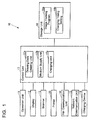
- FIG. 1 illustrates an MFP 10 according to the embodiment.
- the MFP 10 includes an operation unit 11, a display 12, a scanner 13, a printer 20, a fax communication unit 14, a network communication unit 15, a storage unit 16, and a control unit 17.
- the operation unit 11 is an input device such as a button for inputting various operations.
- the display 12 is a display device, such as a Liquid Crystal Display (LCD), which displays various pieces of information.
- the scanner 13, which is a reading device, reads images from a document.
- the printer 20 is a print device that has a mechanism to perform printing on a printing medium such as a paper sheet.
- the network communication unit 15 which is a network communication device, communicates with an external device via a network such as a Local Area Network (LAN) and the Internet.
- the control unit 17 controls the entire MFP10.
- the charging device 18 includes, for example, a coin bender, which collects currency, such as coins, as a charging for printing each time printing is performed, and a key counter, which measures a printing amount corresponding to the charging for printing.
- FIG. 2 illustrates a structure inside the MFP 10.
- the printer 20 includes a cassette 21, which supplies a printing medium 90, and a medium discharge member 22 from which the printing medium 90 is discharged.
- the printer 20 includes a conveyance path 23 for the printing medium 90 from the cassette 21 to the medium discharge member 22.
- the printer 20 includes a large number of conveyance rollers (not illustrated) on the conveyance path 23. The conveyance rollers convey the printing medium 90 along the conveyance path 23.
- the printer 20 includes a printing unit 24, which performs printing on the printing medium 90.
- the printing unit 24 includes photoreceptor drums 24a to 24d, a transfer belt 24e, and a fixing unit 24f.
- the photoreceptor drums 24a to 24d are photoreceptor drums for each of cyan, magenta, yellow, and black, which form images on the surfaces with toner. After the images, which are formed on the surfaces of the photoreceptor drums 24a to 24d with the toner, are transferred to the surface of the transfer belt 24e, the transfer belt 24e transfers the images transferred on the surface with toner to the printing medium 90.
- the fixing unit 24f fixes the image transferred from the transfer belt 24e on the printing medium 90 with toner to the printing medium 90.
- the printer 20 includes a registration roller 25 and a discharge sensor 26.
- the registration roller 25 adjusts a timing of conveying the printing medium 90 such that the image transferred on the surface of the transfer belt 24e with toner is appropriately transferred to the printing medium 90.
- the discharge sensor 26 detects the discharge of the printing medium 90 to the medium discharge member 22.
- the storage unit 16 which is a non-transitory computer-readable recording medium, stores an image forming program 16a to control the MFP 10.
- the image forming program 16a may be installed on the MFP 10 at the production stage of the MFP 10, may be additionally installed from an external storage medium, such as an SD card and a universal serial bus (USB) memory, on the MFP 10, and may be additionally installed from a network on the MFP 10.
- an external storage medium such as an SD card and a universal serial bus (USB) memory
- the storage unit 16 can store a charging timing setting 16b, which indicates a setting of charging timing.
- the charging timing setting 16b is settable according to an instruction via the operation unit 11 or the network communication unit 15. As settable timing by the charging timing setting 16b, any of timings at which the conveyance of the printing medium 90 starts from the cassette 21 with the conveyance rollers of the printer 20 (hereinafter referred to as a "supply start timing") and at which the conveyance rollers of the printer 20 terminate the conveyance of the printing medium 90 to the medium discharge member 22 (hereinafter referred to as a "discharge end timing”) are settable.
- the control unit 17 is a hardware circuit that includes, for example, a Central Processing Unit (CPU), a Read Only Memory (ROM), which stores programs and various data, and a Random Access Memory (RAM) used as the work area for the CPU.
- the CPU executes the programs stored in the ROM or the storage unit 16.
- the control unit 17 By executing the image forming program 16a stored in the storage unit 16, the control unit 17 operates as a drawing data creating unit 17a (a drawing data creating circuit), a medium supply unit 17b (a medium supply circuit), and a charging unit 17c (a charging circuit).
- the drawing data creating unit 17a creates drawing data, which causes the printing unit 24 to perform printing, on each band in order.
- the medium supply unit 17b supplies the printing medium 90 to the printing unit 24.
- the charging unit 17c performs the charging process for printing.
- the drawing data creating unit 17a creates the drawing data based on print data received from the external device via the network communication unit 15 and print data read from the external storage medium, such as an SD card and an USB flash drive, or the storage unit 16.
- the drawing data creating unit 17a creates the drawing data based on an image received from the external device via the network communication unit 15, an image read from the external storage medium, such as an SD card and an USB flash drive, or the storage unit 16, and an image read from the document by the scanner 13.
- the print data includes a specified color of any one of monochrome and color.
- a specified color of any one of monochrome and color is specified.
- the specified color can be specified via a printer driver of the external device or the operation unit 11.
- the drawing data creating unit 17a fixes a color for use for printing, which is performed based on the drawing data by the printing unit 24. That is, the drawing data creating unit 17a includes a color conversion module. For example, even if a specified color is color, when the color included in the image, which is printed actually, is only an achromatic color, the color for use in the drawing data, which is created by the drawing data creating unit 17a, may be monochrome. That is, the color for use, which is fixed by the drawing data creating unit 17a, differs from the specified color in some cases. Accordingly, the charging unit 17c performs charging corresponding to not the specified color but the color for use fixed by the drawing data creating unit 17a. For example, the amount of money charged for printing of color printing per sheet is set higher than that of the monochrome printing.
- FIG. 3 illustrates an example of timings of various processes by the drawing data creating unit 17a.
- the external device creates the print data (Step S51), and then starts transmission of the created print data to the MFP 10 (Step S52).
- the control unit 17 of the MFP 10 starts receiving the print data transmitted from the external device (Step S53), and then starts a job of printing based on the received print data (Step S54).
- the drawing data creating unit 17a of the control unit 17 creates intermediate image data based on the print data (Step S55), and then rasterizes the intermediate image data created at Step S55 (Step S56).
- the drawing data creating unit 17a performs a color conversion process on the rasterized image data (Step S57) to create drawing data.
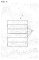
- the drawing data creating unit 17a creates the drawing data for each area or each band 71, which is formed by dividing an area 70 of one page into a plurality of areas, in order.
- the drawing data creating unit 17a each time creating the band 71 of the drawing data, fixes a band-used color, which is used on each band 71 on printing performed by the printing unit 24 based on the drawing data, to any one of monochrome and color.
- the drawing data creating unit 17a after completion of creating the drawing data of one page, fixes the color for use on printing, which is performed by the printing unit 24 based on the drawing data, to any one of monochrome and color. That is, the drawing data creating unit 17a, when the band-used color of all the bands 71 of the drawing data of one page is monochrome, fixes the color for use as monochrome, and when at least one band-used color of the band 71 in the drawing data of one page is color, fixes the color for use as color.
- the drawing data creating unit 17a starts creating the drawing data based on the print data received from the external device via the network communication unit 15.
- the drawing data creating unit 17a starts creating the drawing data based on other print data and image, such as print data input from the external storage medium such as an USB flash drive.
- the medium supply unit 17b illustrated in FIG. 1 performs the primary supply and the secondary supply.
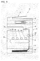
- the primary supply as illustrated in FIG. 5 , supplies the printing medium 90 from the cassette 21 to a specific position, that is, a position of the registration roller 25.
- the secondary supply as illustrated in FIG. 6 , supplies the printing medium 90 from the position of the registration roller 25 to the printing unit 24, and then discharges the printing medium 90 to the medium discharge member 22.
- the MFP 10 advances the printing medium 90 up to the position of the registration roller 25 beforehand by the primary supply, and then, as soon as preparation of a printing process, such as creation of the drawing data by the drawing data creating unit 17a, is completed, ensures execution of printing to the printing medium 90 by the printing unit 24 immediately by the secondary supply. Accordingly, the MFP 10 ensures improving a printing speed.
- the secondary supply starts at a timing t61.
- the drawing data created by the color conversion process at Step S57 is compressed at a timing t62, where the color conversion process at Step S57 is terminated.
- the control unit 17 needs to perform the preparatory work before printing by the printing unit 24.
- the preparatory work includes, for example, decompression of the drawing data created by the color conversion process at Step S57, adjustment of the position of the drawing data based on margins set to the print data, and rotation of the drawing data corresponding to the rotation direction set to the print data.
- the control unit 17 processes the drawing data for each band.
- the medium supply unit 17b starts the secondary supply at a phase of completing the preparatory work by, for example, two bands. Accordingly, the timing t61, where the secondary supply starts is after the timing t62, where the color conversion process at Step S57 is terminated.
- the control unit 17 performs preparatory work for the remaining bands concurrently with the secondary supply.
- the primary supply starts at any of the timing t62, where the color conversion process at Step S57 is terminated and a timing t63, which is previous of the timing t62.
- a timing where the primary supply starts is the timing t63 prior to the timing t62
- the timing t63 may not be the timing illustrated in FIG. 3 as long as after the start of Step S57.
- the control unit 17 starts preparation of the printing unit 24, such as starting warming the fixing unit 24f, for example, at a timing t64, which is near the start timing of the process at Step S55.
- the timing t64 may be prior to the start timing of the process at Step S55, may be at the start timing of the process at Step S55, or may be after the start timing of the process at Step S55.
- the charging unit 17c illustrated in FIG. 1 at a timing set at the charging timing setting 16b, performs charging based on the color for use fixed by the drawing data creating unit 17a.
- FIG. 7 illustrates the operations of the MFP 10 to perform printing.
- the medium supply unit 17b determines, whether or not the drawing data creating unit 17a has completed creating the specific numbers of bands of the drawing data (Step S101).
- the medium supply unit 17b after determining that the drawing data creating unit 17a has completed creating the specific numbers of bands of the drawing data at Step S101, determines, whether or not the charging timing is the supply start timing based on the charging timing setting 16b (Step S102).
- the medium supply unit 17b when determining that the charging timing is not the supply start timing, that is, the charging timing is the discharge end timing at Step S102, performs the primary supply (Step S103).
- Step S104 determines, whether or not the drawing data creating unit 17a has completed creating all the bands of the drawing data.
- the medium supply unit 17b after determining that the drawing data creating unit 17a has completed creating all the bands of the drawing data at Step S104, performs the secondary supply (Step S105).
- the charging unit 17c determines, whether or not the discharge sensor 26 has detected that the printing medium 90 has been discharged to the medium discharge member 22 (Step S106).
- the charging unit 17c after determining that the discharge sensor 26 has detected that the printing medium 90 has been discharged to the medium discharge member 22 at Step S106, performs the charging process corresponding to the color for use fixed by the drawing data creating unit 17a (Step S107), and then terminates the operations illustrated in FIG. 7 .
- the medium supply unit 17b after determining that the charging timing is the supply start timing at Step S102, determines, whether or not the band-used color fixed as color by the drawing data creating unit 17a exists among the colors for band use of the specific numbers of bands of the drawing data (Step S108).
- the medium supply unit 17b after determining that the band-used color fixed as color exists at Step S108, performs the primary supply (Step S109).
- the charging unit 17c performs the charging process, when the color for use fixed by the drawing data creating unit 17a is color (Step S110).
- the medium supply unit 17b determines, whether or not the drawing data creating unit 17a has completed creating all the bands of the drawing data (Step S111).
- the medium supply unit 17b after determining that the drawing data creating unit 17a has completed creating all the bands of the drawing data at Step S111, performs the secondary supply (Step S112).
- the medium supply unit 17b determines, whether or not the discharge sensor 26 has detected that the printing medium 90 has been discharged to the medium discharge member 22 (Step S113).
- the medium supply unit 17b after determining that the discharge sensor 26 has detected that the printing medium 90 has been discharged to the medium discharge member 22 at Step S113, terminates the operations illustrated in FIG. 7 .
- the medium supply unit 17b after determining that the band-used color fixed as color does not exist at Step S108, until determining that the drawing data creating unit 17a has completed creating all the bands of the drawing data, determines, whether or not the drawing data creating unit 17a has completed creating all the bands of the drawing data (Step S114).
- the medium supply unit 17b after determining that the drawing data creating unit 17a has completed creating all the bands of the drawing data at Step S114, performs the primary supply (Step S115).
- the charging unit 17c performs the charging process corresponding to the color for use fixed by the drawing data creating unit 17a (Step S116).
- the medium supply unit 17b performs the process at Step S112.
- the MFP10 when color exists among the colors for band use (YES at Step S108), starts the primary supply prior to completion of creating all the bands of the drawing data (Step S109), and performs the charging process in the case, where the color for use is color, in starting the primary supply (Step S110).
- This can improve the printing speed compared with a configuration that performs the charging process corresponding to the color for use fixed after completion of creating all the bands of the drawing data (YES at Step S114) in starting the primary supply (Step S116).
- the MFP10 when the band-used color fixed as color exists after completion of creating the specific numbers of bands, which number is smaller than the number of all the bands, of the drawing data, starts the primary supply prior to completion of creating all the bands of the drawing data, and performs the charging process in the case, where the color for use is color, in starting the primary supply. This eliminates the need for performing determinations for starting the primary supply and performing the charging process each time the band-used color is fixed. Accordingly, the MFP10 can reduce a process load compare with a configuration that the medium supply unit 17b determines the band-used color on each band for starting the primary supply until the band-used color fixed as color exists.
- the MFP10 when the charging timing is the supply start timing, may cause the medium supply unit 17b to determine the band-used color on each band for starting the primary supply until the band-used color fixed as color exists.
- the image forming apparatus of the disclosure is an MFP in this embodiment, the image forming apparatus may be an image forming apparatus other than the MFP such as a printer-only machine and a copy-only machine, as long as the image forming apparatus performs printing.
Landscapes
- Engineering & Computer Science (AREA)
- Multimedia (AREA)
- Signal Processing (AREA)
- Physics & Mathematics (AREA)
- General Physics & Mathematics (AREA)
- General Engineering & Computer Science (AREA)
- Computing Systems (AREA)
- Health & Medical Sciences (AREA)
- Biomedical Technology (AREA)
- General Health & Medical Sciences (AREA)
- Control Or Security For Electrophotography (AREA)
- Accessory Devices And Overall Control Thereof (AREA)
- Record Information Processing For Printing (AREA)
- Facsimiles In General (AREA)
- Color Electrophotography (AREA)
Abstract
Description
- Unless otherwise indicated herein, the description in this section is not prior art to the claims in this application and is not admitted to be prior art by inclusion in this section.
- There is known an image forming apparatus that includes a printing unit, a drawing data creating unit, and a medium supply unit. The printing unit performs printing on a printing medium. The drawing data creating unit creates drawing data, which causes the printing unit to perform printing. The medium supply unit supplies the printing medium to the printing unit.
- This medium supply unit performs a primary supply and a secondary supply. The primary supply supplies the printing medium to a specific position. The secondary supply supplies the printing medium from the specific position to the printing unit. A typical image forming apparatus starts the primary supply prior to completion of creating the drawing data. This ensures the improved printing speed compared with a configuration that starts the primary supply after completion of creating the drawing data.
- An image forming apparatus according to an aspect of the disclosure includes a printing mechanism, a drawing data creating circuit, a medium supply circuit, and a charging circuit. The printing mechanism is adapted to print on a printing medium. The drawing data creating circuit is adapted to create drawing data for each band in order, the drawing data being adapted to cause the printing mechanism to print. The medium supply circuit is adapted to supply the printing medium to the printing mechanism. The charging circuit is adapted to perform a charging process for printing. The medium supply circuit is adapted to perform: a primary supply supplying the printing medium to a specific position; and a secondary supply supplying the printing medium from the specific position to the printing mechanism. The drawing data creating circuit is adapted to fix a band-used color used for each band in printing, performed based on the drawing data by the printing mechanism, to one of monochrome and color, the drawing data creating circuit being adapted to fix a color for use in printing, performed based on the drawing data by the printing mechanism, to one of monochrome and color. When the band-used color fixed as color by the drawing data creating circuit exists, the medium supply circuit is adapted to start the primary supply prior to completion of creating all the bands of the drawing data by the drawing data creating circuit. When the band-used color fixed as color by the drawing data creating circuit exists, the charging circuit is adapted to perform the charging process in a case, where the color for use is color, in starting the primary supply.
- These as well as other aspects, advantages, and alternatives will become apparent to those of ordinary skill in the art by reading the following detailed description with reference where appropriate to the accompanying drawings. Further, it should be understood that the description provided in this summary section and elsewhere in this document is intended to illustrate the claimed subject matter by way of example and not by way of limitation.
-
-
FIG. 1 illustrates an MFP according to an embodiment of the disclosure; -
FIG. 2 illustrates an internal structure of the MFP according to the embodiment; -
FIG. 3 illustrates an example of timings of various processes by a drawing data creating unit according to the embodiment; -
FIG. 4 illustrates a band processed by the drawing data creating unit according to the embodiment; -
FIG. 5 illustrates the MFP according to the embodiment at a time point of completing execution of a primary supply; -
FIG. 6 illustrates the MFP according to the embodiment while a secondary supply is in execution; and -
FIG. 7 illustrates operations of the MFP according to the embodiment to perform printing. - Example apparatuses are described herein. Other example embodiments or features may further be utilized, and other changes may be made, without departing from the spirit or scope of the subject matter presented herein. In the following detailed description, reference is made to the accompanying drawings, which form a part thereof.
- The exemplary embodiments described herein are not meant to be limiting. It will be readily understood that the aspects of the present disclosure, as generally described herein, and illustrated in the drawings, can be arranged, substituted, combined, separated, and designed in a wide variety of different configurations, all of which are explicitly contemplated herein.
- The following describes an embodiment of the disclosure with reference to the drawings.
- First, the following describes a configuration of a Multifunction Peripheral (MFP) as an image forming apparatus according to the embodiment.
-
FIG. 1 illustrates anMFP 10 according to the embodiment. - As illustrated in
FIG. 1 , the MFP 10 includes anoperation unit 11, adisplay 12, ascanner 13, aprinter 20, afax communication unit 14, anetwork communication unit 15, astorage unit 16, and acontrol unit 17. Theoperation unit 11 is an input device such as a button for inputting various operations. Thedisplay 12 is a display device, such as a Liquid Crystal Display (LCD), which displays various pieces of information. Thescanner 13, which is a reading device, reads images from a document. Theprinter 20 is a print device that has a mechanism to perform printing on a printing medium such as a paper sheet. Thefax communication unit 14, which is a fax device, performs fax communications with an external facsimile device (not illustrated) via a communication line such as a dial-up line. Thenetwork communication unit 15, which is a network communication device, communicates with an external device via a network such as a Local Area Network (LAN) and the Internet. Thestorage unit 16, which is a non-volatile storage device such as a semiconductor memory and a Hard Disk Drive (HDD), stores various pieces of information. Thecontrol unit 17 controls the entire MFP10. - On the MFP10, a
charging device 18, which performs a charging process for printing, is mounted. Thecharging device 18 includes, for example, a coin bender, which collects currency, such as coins, as a charging for printing each time printing is performed, and a key counter, which measures a printing amount corresponding to the charging for printing. -
FIG. 2 illustrates a structure inside theMFP 10. - As illustrated in
FIG. 2 , theprinter 20 includes acassette 21, which supplies aprinting medium 90, and amedium discharge member 22 from which theprinting medium 90 is discharged. - The
printer 20 includes aconveyance path 23 for theprinting medium 90 from thecassette 21 to themedium discharge member 22. Theprinter 20 includes a large number of conveyance rollers (not illustrated) on theconveyance path 23. The conveyance rollers convey theprinting medium 90 along theconveyance path 23. - The
printer 20 includes aprinting unit 24, which performs printing on theprinting medium 90. Theprinting unit 24 includesphotoreceptor drums 24a to 24d, atransfer belt 24e, and afixing unit 24f. Thephotoreceptor drums 24a to 24d are photoreceptor drums for each of cyan, magenta, yellow, and black, which form images on the surfaces with toner. After the images, which are formed on the surfaces of thephotoreceptor drums 24a to 24d with the toner, are transferred to the surface of thetransfer belt 24e, thetransfer belt 24e transfers the images transferred on the surface with toner to theprinting medium 90. Thefixing unit 24f fixes the image transferred from thetransfer belt 24e on theprinting medium 90 with toner to theprinting medium 90. - The
printer 20 includes aregistration roller 25 and adischarge sensor 26. Theregistration roller 25 adjusts a timing of conveying theprinting medium 90 such that the image transferred on the surface of thetransfer belt 24e with toner is appropriately transferred to theprinting medium 90. Thedischarge sensor 26 detects the discharge of theprinting medium 90 to themedium discharge member 22. - As illustrated in
FIG. 1 , thestorage unit 16, which is a non-transitory computer-readable recording medium, stores animage forming program 16a to control theMFP 10. Theimage forming program 16a may be installed on theMFP 10 at the production stage of theMFP 10, may be additionally installed from an external storage medium, such as an SD card and a universal serial bus (USB) memory, on theMFP 10, and may be additionally installed from a network on theMFP 10. - The
storage unit 16 can store a charging timing setting 16b, which indicates a setting of charging timing. The charging timing setting 16b is settable according to an instruction via theoperation unit 11 or thenetwork communication unit 15. As settable timing by the charging timing setting 16b, any of timings at which the conveyance of theprinting medium 90 starts from thecassette 21 with the conveyance rollers of the printer 20 (hereinafter referred to as a "supply start timing") and at which the conveyance rollers of theprinter 20 terminate the conveyance of theprinting medium 90 to the medium discharge member 22 (hereinafter referred to as a "discharge end timing") are settable. When the discharge end timing has been set, if opening the cover of theMFP 10 and removing theprinting medium 90 to outside theMFP 10 after performing printing on theprinting medium 90 by theprinting unit 24 and before the already-printedprinting medium 90 is discharged to themedium discharge member 22, an incorrect operation of not charging possibly occurs. When the supply start timing has been set, such incorrect operation can be prevented. - The
control unit 17 is a hardware circuit that includes, for example, a Central Processing Unit (CPU), a Read Only Memory (ROM), which stores programs and various data, and a Random Access Memory (RAM) used as the work area for the CPU. The CPU executes the programs stored in the ROM or thestorage unit 16. - By executing the
image forming program 16a stored in thestorage unit 16, thecontrol unit 17 operates as a drawingdata creating unit 17a (a drawing data creating circuit), amedium supply unit 17b (a medium supply circuit), and acharging unit 17c (a charging circuit). The drawingdata creating unit 17a creates drawing data, which causes theprinting unit 24 to perform printing, on each band in order. Themedium supply unit 17b supplies theprinting medium 90 to theprinting unit 24. The chargingunit 17c performs the charging process for printing. - The drawing
data creating unit 17a, for example, creates the drawing data based on print data received from the external device via thenetwork communication unit 15 and print data read from the external storage medium, such as an SD card and an USB flash drive, or thestorage unit 16. The drawingdata creating unit 17a creates the drawing data based on an image received from the external device via thenetwork communication unit 15, an image read from the external storage medium, such as an SD card and an USB flash drive, or thestorage unit 16, and an image read from the document by thescanner 13. - The print data includes a specified color of any one of monochrome and color. When the drawing
data creating unit 17a creates the drawing data based on the image, a specified color of any one of monochrome and color is specified. The specified color can be specified via a printer driver of the external device or theoperation unit 11. - To create the drawing data, the drawing
data creating unit 17a fixes a color for use for printing, which is performed based on the drawing data by theprinting unit 24. That is, the drawingdata creating unit 17a includes a color conversion module. For example, even if a specified color is color, when the color included in the image, which is printed actually, is only an achromatic color, the color for use in the drawing data, which is created by the drawingdata creating unit 17a, may be monochrome. That is, the color for use, which is fixed by the drawingdata creating unit 17a, differs from the specified color in some cases. Accordingly, the chargingunit 17c performs charging corresponding to not the specified color but the color for use fixed by the drawingdata creating unit 17a. For example, the amount of money charged for printing of color printing per sheet is set higher than that of the monochrome printing. -
FIG. 3 illustrates an example of timings of various processes by the drawingdata creating unit 17a. - As illustrated in
FIG. 3 , the external device creates the print data (Step S51), and then starts transmission of the created print data to the MFP 10 (Step S52). Accordingly, thecontrol unit 17 of theMFP 10 starts receiving the print data transmitted from the external device (Step S53), and then starts a job of printing based on the received print data (Step S54). Then, when performing the job started at Step S54, the drawingdata creating unit 17a of thecontrol unit 17 creates intermediate image data based on the print data (Step S55), and then rasterizes the intermediate image data created at Step S55 (Step S56). The drawingdata creating unit 17a performs a color conversion process on the rasterized image data (Step S57) to create drawing data. - The drawing
data creating unit 17a, as illustrated inFIG. 4 , creates the drawing data for each area or eachband 71, which is formed by dividing anarea 70 of one page into a plurality of areas, in order. Here, the drawingdata creating unit 17a, each time creating theband 71 of the drawing data, fixes a band-used color, which is used on eachband 71 on printing performed by theprinting unit 24 based on the drawing data, to any one of monochrome and color. - The drawing
data creating unit 17a, after completion of creating the drawing data of one page, fixes the color for use on printing, which is performed by theprinting unit 24 based on the drawing data, to any one of monochrome and color. That is, the drawingdata creating unit 17a, when the band-used color of all thebands 71 of the drawing data of one page is monochrome, fixes the color for use as monochrome, and when at least one band-used color of theband 71 in the drawing data of one page is color, fixes the color for use as color. - In the example illustrated in
FIG. 3 , the drawingdata creating unit 17a starts creating the drawing data based on the print data received from the external device via thenetwork communication unit 15. However, the same applies, when the drawingdata creating unit 17a starts creating the drawing data based on other print data and image, such as print data input from the external storage medium such as an USB flash drive. - The
medium supply unit 17b illustrated inFIG. 1 performs the primary supply and the secondary supply. The primary supply, as illustrated inFIG. 5 , supplies theprinting medium 90 from thecassette 21 to a specific position, that is, a position of theregistration roller 25. The secondary supply, as illustrated inFIG. 6 , supplies theprinting medium 90 from the position of theregistration roller 25 to theprinting unit 24, and then discharges theprinting medium 90 to themedium discharge member 22. - The
MFP 10 advances theprinting medium 90 up to the position of theregistration roller 25 beforehand by the primary supply, and then, as soon as preparation of a printing process, such as creation of the drawing data by the drawingdata creating unit 17a, is completed, ensures execution of printing to theprinting medium 90 by theprinting unit 24 immediately by the secondary supply. Accordingly, theMFP 10 ensures improving a printing speed. - In the example illustrated in
FIG. 3 , for example, the secondary supply starts at a timing t61. The drawing data created by the color conversion process at Step S57 is compressed at a timing t62, where the color conversion process at Step S57 is terminated. Accordingly, thecontrol unit 17 needs to perform the preparatory work before printing by theprinting unit 24. The preparatory work includes, for example, decompression of the drawing data created by the color conversion process at Step S57, adjustment of the position of the drawing data based on margins set to the print data, and rotation of the drawing data corresponding to the rotation direction set to the print data. Thecontrol unit 17 processes the drawing data for each band. Themedium supply unit 17b starts the secondary supply at a phase of completing the preparatory work by, for example, two bands. Accordingly, the timing t61, where the secondary supply starts is after the timing t62, where the color conversion process at Step S57 is terminated. Thecontrol unit 17 performs preparatory work for the remaining bands concurrently with the secondary supply. - In the example illustrated in
FIG. 3 , for example, the primary supply starts at any of the timing t62, where the color conversion process at Step S57 is terminated and a timing t63, which is previous of the timing t62. When a timing, where the primary supply starts is the timing t63 prior to the timing t62, the timing t63 may not be the timing illustrated inFIG. 3 as long as after the start of Step S57. - The
control unit 17 starts preparation of theprinting unit 24, such as starting warming the fixingunit 24f, for example, at a timing t64, which is near the start timing of the process at Step S55. The timing t64 may be prior to the start timing of the process at Step S55, may be at the start timing of the process at Step S55, or may be after the start timing of the process at Step S55. - The charging
unit 17c illustrated inFIG. 1 , at a timing set at the charging timing setting 16b, performs charging based on the color for use fixed by the drawingdata creating unit 17a. - Next, the following describes operations of the
MFP 10. -
FIG. 7 illustrates the operations of theMFP 10 to perform printing. - As shown in
FIG. 7 , themedium supply unit 17b, until determining that the drawingdata creating unit 17a has completed creating a specific numbers of bands, which number is smaller than the number of all the bands, of the drawing data, determines, whether or not the drawingdata creating unit 17a has completed creating the specific numbers of bands of the drawing data (Step S101). - The
medium supply unit 17b, after determining that the drawingdata creating unit 17a has completed creating the specific numbers of bands of the drawing data at Step S101, determines, whether or not the charging timing is the supply start timing based on the charging timing setting 16b (Step S102). - The
medium supply unit 17b, when determining that the charging timing is not the supply start timing, that is, the charging timing is the discharge end timing at Step S102, performs the primary supply (Step S103). - Next, the
medium supply unit 17b, until determining that the drawingdata creating unit 17a has completed creating all the bands of the drawing data, determines, whether or not the drawingdata creating unit 17a has completed creating all the bands of the drawing data (Step S104). - The
medium supply unit 17b, after determining that the drawingdata creating unit 17a has completed creating all the bands of the drawing data at Step S104, performs the secondary supply (Step S105). - Next, the charging
unit 17c, until determining that thedischarge sensor 26 has detected that theprinting medium 90 has been discharged to themedium discharge member 22, determines, whether or not thedischarge sensor 26 has detected that theprinting medium 90 has been discharged to the medium discharge member 22 (Step S106). - The charging
unit 17c, after determining that thedischarge sensor 26 has detected that theprinting medium 90 has been discharged to themedium discharge member 22 at Step S106, performs the charging process corresponding to the color for use fixed by the drawingdata creating unit 17a (Step S107), and then terminates the operations illustrated inFIG. 7 . - The
medium supply unit 17b, after determining that the charging timing is the supply start timing at Step S102, determines, whether or not the band-used color fixed as color by the drawingdata creating unit 17a exists among the colors for band use of the specific numbers of bands of the drawing data (Step S108). - The
medium supply unit 17b, after determining that the band-used color fixed as color exists at Step S108, performs the primary supply (Step S109). - Next, the charging
unit 17c performs the charging process, when the color for use fixed by the drawingdata creating unit 17a is color (Step S110). - Next, the
medium supply unit 17b, until determining that the drawingdata creating unit 17a has completed creating all the bands of the drawing data, determines, whether or not the drawingdata creating unit 17a has completed creating all the bands of the drawing data (Step S111). - The
medium supply unit 17b, after determining that the drawingdata creating unit 17a has completed creating all the bands of the drawing data at Step S111, performs the secondary supply (Step S112). - Next, the
medium supply unit 17b, until determining that thedischarge sensor 26 has detected that theprinting medium 90 has been discharged to themedium discharge member 22, determines, whether or not thedischarge sensor 26 has detected that theprinting medium 90 has been discharged to the medium discharge member 22 (Step S113). - The
medium supply unit 17b, after determining that thedischarge sensor 26 has detected that theprinting medium 90 has been discharged to themedium discharge member 22 at Step S113, terminates the operations illustrated inFIG. 7 . - The
medium supply unit 17b, after determining that the band-used color fixed as color does not exist at Step S108, until determining that the drawingdata creating unit 17a has completed creating all the bands of the drawing data, determines, whether or not the drawingdata creating unit 17a has completed creating all the bands of the drawing data (Step S114). - The
medium supply unit 17b, after determining that the drawingdata creating unit 17a has completed creating all the bands of the drawing data at Step S114, performs the primary supply (Step S115). - Next, the charging
unit 17c performs the charging process corresponding to the color for use fixed by the drawingdata creating unit 17a (Step S116). - Next, the
medium supply unit 17b performs the process at Step S112. - As described above, the MFP10, when color exists among the colors for band use (YES at Step S108), starts the primary supply prior to completion of creating all the bands of the drawing data (Step S109), and performs the charging process in the case, where the color for use is color, in starting the primary supply (Step S110). This can improve the printing speed compared with a configuration that performs the charging process corresponding to the color for use fixed after completion of creating all the bands of the drawing data (YES at Step S114) in starting the primary supply (Step S116).
- The MFP10, when the band-used color fixed as color exists after completion of creating the specific numbers of bands, which number is smaller than the number of all the bands, of the drawing data, starts the primary supply prior to completion of creating all the bands of the drawing data, and performs the charging process in the case, where the color for use is color, in starting the primary supply. This eliminates the need for performing determinations for starting the primary supply and performing the charging process each time the band-used color is fixed. Accordingly, the MFP10 can reduce a process load compare with a configuration that the
medium supply unit 17b determines the band-used color on each band for starting the primary supply until the band-used color fixed as color exists. - The MFP10, when the charging timing is the supply start timing, may cause the
medium supply unit 17b to determine the band-used color on each band for starting the primary supply until the band-used color fixed as color exists. - While the image forming apparatus of the disclosure is an MFP in this embodiment, the image forming apparatus may be an image forming apparatus other than the MFP such as a printer-only machine and a copy-only machine, as long as the image forming apparatus performs printing.
- While various aspects and embodiments have been disclosed herein, other aspects and embodiments will be apparent to those skilled in the art. The various aspects and embodiments disclosed herein are for purposes of illustration and are not intended to be limiting, with the true scope and spirit being indicated by the following claims.
Claims (3)
- An image forming apparatus (10) comprising:- a printing mechanism (24) that is adapted to print on a printing medium (90);- a drawing data creating circuit (17a) that is adapted to create drawing data for each band in order, the drawing data being adapted to cause the printing mechanism (24) to print;- a medium supply circuit (17b) that is adapted to supply the printing medium (90) to the printing mechanism (24); and- a charging circuit (17c) that is adapted to perform a charging process for printing,wherein the drawing data creating circuit (17a) is adapted to fix a band-used color used for each band in printing, performed based on the drawing data by the printing mechanism (24), to one of monochrome and color, the drawing data creating circuit (17a) being adapted to fix a color for use in printing, performed based on the drawing data by the printing mechanism (24), to one of monochrome and color,
wherein the medium supply circuit (17b) is adapted to perform:- a primary supply supplying the printing medium (90) to a specific position; and- a secondary supply supplying the printing medium (90) from the specific position to the printing mechanism (24),
wherein, when the band-used color fixed as color by the drawing data creating circuit (17a) exists, the medium supply circuit (17b) is adapted to start the primary supply prior to completion of creating all the bands of the drawing data by the drawing data creating circuit (17a), and
wherein, when the band-used color fixed as color by the drawing data creating circuit (17a) exists, the charging circuit (17c) is adapted to perform the charging process in a case, where the color for use is color, in starting the primary supply. - The image forming apparatus (10) according to claim 1,
wherein, when the band-used color fixed as color by the drawing data creating circuit (17a) exists after completion of creating a specific count of bands of the drawing data by the drawing data creating circuit (17a), the count being smaller than a count of all the bands, the medium supply circuit (17b) is adapted to start the primary supply prior to completion of creating all the bands of the drawing data by the drawing data creating circuit (17a), and
wherein, when the band-used color fixed as color by the drawing data creating circuit (17a) exists after completion of creating the specific count of bands by the drawing data creating circuit (17a), the charging circuit (17c) is adapted to perform the charging process in a case, where the color for use is color, in starting the primary supply. - A non-transitory computer-readable recording medium storing an image forming program, the image forming program being adapted to cause an image forming apparatus (10) that includes a printing mechanism (24) performing printing on a printing medium (90) to operate as:- a drawing data creating circuit (17a) that is adapted to create drawing data for each band in order, the drawing data being adapted to cause the printing mechanism (24) to print;- a medium supply circuit (17b) that is adapted to supply the printing medium (90) to the printing mechanism (24); and- a charging circuit (17c) that is adapted to perform a charging process for printing,wherein the drawing data creating circuit (17a) is adapted to fix a band-used color used for each band in printing, performed based on the drawing data by the printing mechanism (24), to one of monochrome and color, the drawing data creating circuit (17a) being adapted to fix a color for use in printing, performed based on the drawing data by the printing mechanism (24), to one of monochrome and color,
wherein the medium supply circuit (17b) is adapted to perform:- a primary supply supplying the printing medium (90) to a specific position; and- a secondary supply supplying the printing medium (90) from the specific position to the printing mechanism (24),
wherein, when the band-used color fixed as color by the drawing data creating circuit (17a) exists, the medium supply circuit (17b) is adapted to start the primary supply prior to completion of creating all the bands of the drawing data by the drawing data creating circuit (17a), and
wherein, when the band-used color fixed as color by the drawing data creating circuit (17a) exists, the charging circuit (17c) is adapted to perform the charging process in a case, where the color for use is color, in starting the primary supply.
Applications Claiming Priority (1)
| Application Number | Priority Date | Filing Date | Title |
|---|---|---|---|
| JP2015129777A JP6299685B2 (en) | 2015-06-29 | 2015-06-29 | Image forming apparatus and image forming program |
Publications (2)
| Publication Number | Publication Date |
|---|---|
| EP3112939A1 true EP3112939A1 (en) | 2017-01-04 |
| EP3112939B1 EP3112939B1 (en) | 2019-09-11 |
Family
ID=56296469
Family Applications (1)
| Application Number | Title | Priority Date | Filing Date |
|---|---|---|---|
| EP16172320.0A Active EP3112939B1 (en) | 2015-06-29 | 2016-05-31 | Image forming apparatus that improves printing speed and recording medium |
Country Status (4)
| Country | Link |
|---|---|
| US (1) | US9571682B2 (en) |
| EP (1) | EP3112939B1 (en) |
| JP (1) | JP6299685B2 (en) |
| CN (1) | CN106303129B (en) |
Families Citing this family (1)
| Publication number | Priority date | Publication date | Assignee | Title |
|---|---|---|---|---|
| US10582091B1 (en) * | 2019-03-11 | 2020-03-03 | Xerox Corporation | Auto-color copy in software based image path |
Citations (3)
| Publication number | Priority date | Publication date | Assignee | Title |
|---|---|---|---|---|
| JP2000238386A (en) * | 1999-02-25 | 2000-09-05 | Seiko Epson Corp | PRINT HOST, PRINTER, AND PRINT SYSTEM WITH THEM |
| JP2007226420A (en) * | 2006-02-22 | 2007-09-06 | Seiko Epson Corp | Printer control program, printer control method, and printer system |
| JP2013088773A (en) * | 2011-10-21 | 2013-05-13 | Konica Minolta Business Technologies Inc | Image forming apparatus and image forming apparatus control method |
Family Cites Families (15)
| Publication number | Priority date | Publication date | Assignee | Title |
|---|---|---|---|---|
| JP2001246794A (en) * | 2000-03-03 | 2001-09-11 | Fuji Xerox Co Ltd | Image forming device |
| JP2003076160A (en) * | 2001-03-02 | 2003-03-14 | Ricoh Co Ltd | Image forming apparatus, image forming method, and double-side transfer method |
| JP2004077881A (en) * | 2002-08-20 | 2004-03-11 | Oki Data Corp | Image recording device |
| US6957022B2 (en) * | 2003-02-07 | 2005-10-18 | Sharp Kabushiki Kaisha | Image forming apparatus |
| US20070195367A1 (en) * | 2006-02-22 | 2007-08-23 | Seiko Epson Corporation | Computer readable medium recording a printer control program, printer control method, and printer system |
| JP2007322774A (en) * | 2006-06-01 | 2007-12-13 | Fuji Xerox Co Ltd | Image forming apparatus |
| JP5268764B2 (en) * | 2008-08-29 | 2013-08-21 | 京セラドキュメントソリューションズ株式会社 | Discharge device for image forming apparatus |
| JP5227137B2 (en) * | 2008-10-17 | 2013-07-03 | 株式会社沖データ | Image forming apparatus |
| JP5402314B2 (en) * | 2009-03-17 | 2014-01-29 | 株式会社リコー | Fixing apparatus and image forming apparatus |
| JP4975149B2 (en) * | 2010-08-04 | 2012-07-11 | シャープ株式会社 | Printing device |
| JP5674240B2 (en) * | 2010-11-04 | 2015-02-25 | 株式会社リコー | Image forming apparatus |
| JP6143449B2 (en) * | 2012-12-18 | 2017-06-07 | キヤノン株式会社 | An apparatus, method, and program for determining the color of an output image in an image forming apparatus. |
| JP6218456B2 (en) * | 2013-06-28 | 2017-10-25 | キヤノン株式会社 | Printing apparatus, communication method, and program |
| JP6213378B2 (en) * | 2013-07-31 | 2017-10-18 | 京セラドキュメントソリューションズ株式会社 | Image forming apparatus and image forming method |
| US9592992B2 (en) * | 2014-12-19 | 2017-03-14 | Canon Kabushiki Kaisha | Image forming apparatus |
-
2015
- 2015-06-29 JP JP2015129777A patent/JP6299685B2/en not_active Expired - Fee Related
-
2016
- 2016-05-09 US US15/150,072 patent/US9571682B2/en not_active Expired - Fee Related
- 2016-05-26 CN CN201610357395.XA patent/CN106303129B/en not_active Expired - Fee Related
- 2016-05-31 EP EP16172320.0A patent/EP3112939B1/en active Active
Patent Citations (3)
| Publication number | Priority date | Publication date | Assignee | Title |
|---|---|---|---|---|
| JP2000238386A (en) * | 1999-02-25 | 2000-09-05 | Seiko Epson Corp | PRINT HOST, PRINTER, AND PRINT SYSTEM WITH THEM |
| JP2007226420A (en) * | 2006-02-22 | 2007-09-06 | Seiko Epson Corp | Printer control program, printer control method, and printer system |
| JP2013088773A (en) * | 2011-10-21 | 2013-05-13 | Konica Minolta Business Technologies Inc | Image forming apparatus and image forming apparatus control method |
Also Published As
| Publication number | Publication date |
|---|---|
| JP2017017414A (en) | 2017-01-19 |
| JP6299685B2 (en) | 2018-03-28 |
| EP3112939B1 (en) | 2019-09-11 |
| US20160381238A1 (en) | 2016-12-29 |
| US9571682B2 (en) | 2017-02-14 |
| CN106303129B (en) | 2019-02-05 |
| CN106303129A (en) | 2017-01-04 |
Similar Documents
| Publication | Publication Date | Title |
|---|---|---|
| US9456107B2 (en) | Image forming apparatus, image printing method, and computer-readable recording medium having stored therein image printing control program | |
| US10782642B2 (en) | Image forming apparatus, image forming system, management apparatus, and non-transitory computer readable recording medium storing program | |
| US20120287444A1 (en) | Image forming apparatus, control method thereof, and storage medium | |
| JP2020030358A (en) | Image forming system, image inspection method and program | |
| JP6129785B2 (en) | Image forming apparatus and printer driver | |
| EP3076284B1 (en) | Image forming apparatus that automatically changes start time of feeding print medium in response to state and recording medium | |
| EP3112939B1 (en) | Image forming apparatus that improves printing speed and recording medium | |
| JP6213515B2 (en) | Image forming apparatus, image forming system, and image forming method | |
| US9674394B2 (en) | Image forming apparatus that ensures prompt start of printing medium supply, recording medium, and image forming method | |
| JP2015121826A (en) | Sheet discharge device, image formation device | |
| JP7383955B2 (en) | image forming device | |
| JP6268495B2 (en) | Image forming apparatus and image forming program | |
| JP6165066B2 (en) | Image forming apparatus and image forming method | |
| JP6827972B2 (en) | Image forming device | |
| JP6331033B2 (en) | Image forming apparatus and control program | |
| JP6805779B2 (en) | Image forming apparatus, image forming system, and image processing method | |
| US20200364007A1 (en) | Image forming device, control method of image forming device, and program | |
| JP2018072571A (en) | Image forming system and alignment method | |
| JP2015105171A (en) | Image forming apparatus | |
| JP2023065190A (en) | image forming system | |
| EP3214500A1 (en) | Image-forming device having a plurality of paper-supply cassettes | |
| CN112578649A (en) | Image forming apparatus with a toner supply device | |
| JP2018051771A (en) | Image forming apparatus and image forming program | |
| WO2017026328A1 (en) | Image forming apparatus |
Legal Events
| Date | Code | Title | Description |
|---|---|---|---|
| PUAI | Public reference made under article 153(3) epc to a published international application that has entered the european phase |
Free format text: ORIGINAL CODE: 0009012 |
|
| STAA | Information on the status of an ep patent application or granted ep patent |
Free format text: STATUS: THE APPLICATION HAS BEEN PUBLISHED |
|
| AK | Designated contracting states |
Kind code of ref document: A1 Designated state(s): AL AT BE BG CH CY CZ DE DK EE ES FI FR GB GR HR HU IE IS IT LI LT LU LV MC MK MT NL NO PL PT RO RS SE SI SK SM TR |
|
| AX | Request for extension of the european patent |
Extension state: BA ME |
|
| STAA | Information on the status of an ep patent application or granted ep patent |
Free format text: STATUS: REQUEST FOR EXAMINATION WAS MADE |
|
| 17P | Request for examination filed |
Effective date: 20170522 |
|
| RBV | Designated contracting states (corrected) |
Designated state(s): AL AT BE BG CH CY CZ DE DK EE ES FI FR GB GR HR HU IE IS IT LI LT LU LV MC MK MT NL NO PL PT RO RS SE SI SK SM TR |
|
| STAA | Information on the status of an ep patent application or granted ep patent |
Free format text: STATUS: EXAMINATION IS IN PROGRESS |
|
| 17Q | First examination report despatched |
Effective date: 20180321 |
|
| GRAP | Despatch of communication of intention to grant a patent |
Free format text: ORIGINAL CODE: EPIDOSNIGR1 |
|
| STAA | Information on the status of an ep patent application or granted ep patent |
Free format text: STATUS: GRANT OF PATENT IS INTENDED |
|
| INTG | Intention to grant announced |
Effective date: 20190325 |
|
| RAP1 | Party data changed (applicant data changed or rights of an application transferred) |
Owner name: KYOCERA DOCUMENT SOLUTIONS INC. |
|
| GRAS | Grant fee paid |
Free format text: ORIGINAL CODE: EPIDOSNIGR3 |
|
| GRAA | (expected) grant |
Free format text: ORIGINAL CODE: 0009210 |
|
| STAA | Information on the status of an ep patent application or granted ep patent |
Free format text: STATUS: THE PATENT HAS BEEN GRANTED |
|
| AK | Designated contracting states |
Kind code of ref document: B1 Designated state(s): AL AT BE BG CH CY CZ DE DK EE ES FI FR GB GR HR HU IE IS IT LI LT LU LV MC MK MT NL NO PL PT RO RS SE SI SK SM TR |
|
| REG | Reference to a national code |
Ref country code: GB Ref legal event code: FG4D |
|
| REG | Reference to a national code |
Ref country code: CH Ref legal event code: EP |
|
| REG | Reference to a national code |
Ref country code: AT Ref legal event code: REF Ref document number: 1179228 Country of ref document: AT Kind code of ref document: T Effective date: 20190915 |
|
| REG | Reference to a national code |
Ref country code: DE Ref legal event code: R096 Ref document number: 602016020243 Country of ref document: DE Ref country code: IE Ref legal event code: FG4D |
|
| REG | Reference to a national code |
Ref country code: NL Ref legal event code: MP Effective date: 20190911 |
|
| REG | Reference to a national code |
Ref country code: LT Ref legal event code: MG4D |
|
| PG25 | Lapsed in a contracting state [announced via postgrant information from national office to epo] |
Ref country code: FI Free format text: LAPSE BECAUSE OF FAILURE TO SUBMIT A TRANSLATION OF THE DESCRIPTION OR TO PAY THE FEE WITHIN THE PRESCRIBED TIME-LIMIT Effective date: 20190911 Ref country code: HR Free format text: LAPSE BECAUSE OF FAILURE TO SUBMIT A TRANSLATION OF THE DESCRIPTION OR TO PAY THE FEE WITHIN THE PRESCRIBED TIME-LIMIT Effective date: 20190911 Ref country code: BG Free format text: LAPSE BECAUSE OF FAILURE TO SUBMIT A TRANSLATION OF THE DESCRIPTION OR TO PAY THE FEE WITHIN THE PRESCRIBED TIME-LIMIT Effective date: 20191211 Ref country code: SE Free format text: LAPSE BECAUSE OF FAILURE TO SUBMIT A TRANSLATION OF THE DESCRIPTION OR TO PAY THE FEE WITHIN THE PRESCRIBED TIME-LIMIT Effective date: 20190911 Ref country code: NO Free format text: LAPSE BECAUSE OF FAILURE TO SUBMIT A TRANSLATION OF THE DESCRIPTION OR TO PAY THE FEE WITHIN THE PRESCRIBED TIME-LIMIT Effective date: 20191211 Ref country code: LT Free format text: LAPSE BECAUSE OF FAILURE TO SUBMIT A TRANSLATION OF THE DESCRIPTION OR TO PAY THE FEE WITHIN THE PRESCRIBED TIME-LIMIT Effective date: 20190911 |
|
| PG25 | Lapsed in a contracting state [announced via postgrant information from national office to epo] |
Ref country code: LV Free format text: LAPSE BECAUSE OF FAILURE TO SUBMIT A TRANSLATION OF THE DESCRIPTION OR TO PAY THE FEE WITHIN THE PRESCRIBED TIME-LIMIT Effective date: 20190911 Ref country code: GR Free format text: LAPSE BECAUSE OF FAILURE TO SUBMIT A TRANSLATION OF THE DESCRIPTION OR TO PAY THE FEE WITHIN THE PRESCRIBED TIME-LIMIT Effective date: 20191212 Ref country code: ES Free format text: LAPSE BECAUSE OF FAILURE TO SUBMIT A TRANSLATION OF THE DESCRIPTION OR TO PAY THE FEE WITHIN THE PRESCRIBED TIME-LIMIT Effective date: 20190911 Ref country code: AL Free format text: LAPSE BECAUSE OF FAILURE TO SUBMIT A TRANSLATION OF THE DESCRIPTION OR TO PAY THE FEE WITHIN THE PRESCRIBED TIME-LIMIT Effective date: 20190911 Ref country code: RS Free format text: LAPSE BECAUSE OF FAILURE TO SUBMIT A TRANSLATION OF THE DESCRIPTION OR TO PAY THE FEE WITHIN THE PRESCRIBED TIME-LIMIT Effective date: 20190911 |
|
| REG | Reference to a national code |
Ref country code: AT Ref legal event code: MK05 Ref document number: 1179228 Country of ref document: AT Kind code of ref document: T Effective date: 20190911 |
|
| PG25 | Lapsed in a contracting state [announced via postgrant information from national office to epo] |
Ref country code: EE Free format text: LAPSE BECAUSE OF FAILURE TO SUBMIT A TRANSLATION OF THE DESCRIPTION OR TO PAY THE FEE WITHIN THE PRESCRIBED TIME-LIMIT Effective date: 20190911 Ref country code: NL Free format text: LAPSE BECAUSE OF FAILURE TO SUBMIT A TRANSLATION OF THE DESCRIPTION OR TO PAY THE FEE WITHIN THE PRESCRIBED TIME-LIMIT Effective date: 20190911 Ref country code: PL Free format text: LAPSE BECAUSE OF FAILURE TO SUBMIT A TRANSLATION OF THE DESCRIPTION OR TO PAY THE FEE WITHIN THE PRESCRIBED TIME-LIMIT Effective date: 20190911 Ref country code: RO Free format text: LAPSE BECAUSE OF FAILURE TO SUBMIT A TRANSLATION OF THE DESCRIPTION OR TO PAY THE FEE WITHIN THE PRESCRIBED TIME-LIMIT Effective date: 20190911 Ref country code: PT Free format text: LAPSE BECAUSE OF FAILURE TO SUBMIT A TRANSLATION OF THE DESCRIPTION OR TO PAY THE FEE WITHIN THE PRESCRIBED TIME-LIMIT Effective date: 20200113 Ref country code: AT Free format text: LAPSE BECAUSE OF FAILURE TO SUBMIT A TRANSLATION OF THE DESCRIPTION OR TO PAY THE FEE WITHIN THE PRESCRIBED TIME-LIMIT Effective date: 20190911 Ref country code: IT Free format text: LAPSE BECAUSE OF FAILURE TO SUBMIT A TRANSLATION OF THE DESCRIPTION OR TO PAY THE FEE WITHIN THE PRESCRIBED TIME-LIMIT Effective date: 20190911 |
|
| PG25 | Lapsed in a contracting state [announced via postgrant information from national office to epo] |
Ref country code: CZ Free format text: LAPSE BECAUSE OF FAILURE TO SUBMIT A TRANSLATION OF THE DESCRIPTION OR TO PAY THE FEE WITHIN THE PRESCRIBED TIME-LIMIT Effective date: 20190911 Ref country code: SK Free format text: LAPSE BECAUSE OF FAILURE TO SUBMIT A TRANSLATION OF THE DESCRIPTION OR TO PAY THE FEE WITHIN THE PRESCRIBED TIME-LIMIT Effective date: 20190911 Ref country code: SM Free format text: LAPSE BECAUSE OF FAILURE TO SUBMIT A TRANSLATION OF THE DESCRIPTION OR TO PAY THE FEE WITHIN THE PRESCRIBED TIME-LIMIT Effective date: 20190911 Ref country code: IS Free format text: LAPSE BECAUSE OF FAILURE TO SUBMIT A TRANSLATION OF THE DESCRIPTION OR TO PAY THE FEE WITHIN THE PRESCRIBED TIME-LIMIT Effective date: 20200224 |
|
| REG | Reference to a national code |
Ref country code: DE Ref legal event code: R097 Ref document number: 602016020243 Country of ref document: DE |
|
| PLBE | No opposition filed within time limit |
Free format text: ORIGINAL CODE: 0009261 |
|
| STAA | Information on the status of an ep patent application or granted ep patent |
Free format text: STATUS: NO OPPOSITION FILED WITHIN TIME LIMIT |
|
| PG2D | Information on lapse in contracting state deleted |
Ref country code: IS |
|
| PG25 | Lapsed in a contracting state [announced via postgrant information from national office to epo] |
Ref country code: DK Free format text: LAPSE BECAUSE OF FAILURE TO SUBMIT A TRANSLATION OF THE DESCRIPTION OR TO PAY THE FEE WITHIN THE PRESCRIBED TIME-LIMIT Effective date: 20190911 Ref country code: IS Free format text: LAPSE BECAUSE OF FAILURE TO SUBMIT A TRANSLATION OF THE DESCRIPTION OR TO PAY THE FEE WITHIN THE PRESCRIBED TIME-LIMIT Effective date: 20200112 |
|
| PGFP | Annual fee paid to national office [announced via postgrant information from national office to epo] |
Ref country code: FR Payment date: 20200414 Year of fee payment: 5 Ref country code: DE Payment date: 20200519 Year of fee payment: 5 |
|
| 26N | No opposition filed |
Effective date: 20200615 |
|
| PG25 | Lapsed in a contracting state [announced via postgrant information from national office to epo] |
Ref country code: SI Free format text: LAPSE BECAUSE OF FAILURE TO SUBMIT A TRANSLATION OF THE DESCRIPTION OR TO PAY THE FEE WITHIN THE PRESCRIBED TIME-LIMIT Effective date: 20190911 |
|
| PGFP | Annual fee paid to national office [announced via postgrant information from national office to epo] |
Ref country code: GB Payment date: 20200520 Year of fee payment: 5 |
|
| PG25 | Lapsed in a contracting state [announced via postgrant information from national office to epo] |
Ref country code: LI Free format text: LAPSE BECAUSE OF NON-PAYMENT OF DUE FEES Effective date: 20200531 Ref country code: MC Free format text: LAPSE BECAUSE OF FAILURE TO SUBMIT A TRANSLATION OF THE DESCRIPTION OR TO PAY THE FEE WITHIN THE PRESCRIBED TIME-LIMIT Effective date: 20190911 Ref country code: CH Free format text: LAPSE BECAUSE OF NON-PAYMENT OF DUE FEES Effective date: 20200531 |
|
| REG | Reference to a national code |
Ref country code: BE Ref legal event code: MM Effective date: 20200531 |
|
| PG25 | Lapsed in a contracting state [announced via postgrant information from national office to epo] |
Ref country code: LU Free format text: LAPSE BECAUSE OF NON-PAYMENT OF DUE FEES Effective date: 20200531 |
|
| PG25 | Lapsed in a contracting state [announced via postgrant information from national office to epo] |
Ref country code: IE Free format text: LAPSE BECAUSE OF NON-PAYMENT OF DUE FEES Effective date: 20200531 |
|
| PG25 | Lapsed in a contracting state [announced via postgrant information from national office to epo] |
Ref country code: BE Free format text: LAPSE BECAUSE OF NON-PAYMENT OF DUE FEES Effective date: 20200531 |
|
| REG | Reference to a national code |
Ref country code: DE Ref legal event code: R119 Ref document number: 602016020243 Country of ref document: DE |
|
| GBPC | Gb: european patent ceased through non-payment of renewal fee |
Effective date: 20210531 |
|
| PG25 | Lapsed in a contracting state [announced via postgrant information from national office to epo] |
Ref country code: GB Free format text: LAPSE BECAUSE OF NON-PAYMENT OF DUE FEES Effective date: 20210531 Ref country code: DE Free format text: LAPSE BECAUSE OF NON-PAYMENT OF DUE FEES Effective date: 20211201 |
|
| PG25 | Lapsed in a contracting state [announced via postgrant information from national office to epo] |
Ref country code: TR Free format text: LAPSE BECAUSE OF FAILURE TO SUBMIT A TRANSLATION OF THE DESCRIPTION OR TO PAY THE FEE WITHIN THE PRESCRIBED TIME-LIMIT Effective date: 20190911 Ref country code: MT Free format text: LAPSE BECAUSE OF FAILURE TO SUBMIT A TRANSLATION OF THE DESCRIPTION OR TO PAY THE FEE WITHIN THE PRESCRIBED TIME-LIMIT Effective date: 20190911 Ref country code: FR Free format text: LAPSE BECAUSE OF NON-PAYMENT OF DUE FEES Effective date: 20210531 Ref country code: CY Free format text: LAPSE BECAUSE OF FAILURE TO SUBMIT A TRANSLATION OF THE DESCRIPTION OR TO PAY THE FEE WITHIN THE PRESCRIBED TIME-LIMIT Effective date: 20190911 |
|
| PG25 | Lapsed in a contracting state [announced via postgrant information from national office to epo] |
Ref country code: MK Free format text: LAPSE BECAUSE OF FAILURE TO SUBMIT A TRANSLATION OF THE DESCRIPTION OR TO PAY THE FEE WITHIN THE PRESCRIBED TIME-LIMIT Effective date: 20190911 |