EP3112824B1 - Device and method for determining a characteristic value for an object - Google Patents
Device and method for determining a characteristic value for an object Download PDFInfo
- Publication number
- EP3112824B1 EP3112824B1 EP16173923.0A EP16173923A EP3112824B1 EP 3112824 B1 EP3112824 B1 EP 3112824B1 EP 16173923 A EP16173923 A EP 16173923A EP 3112824 B1 EP3112824 B1 EP 3112824B1
- Authority
- EP
- European Patent Office
- Prior art keywords
- signal
- input signal
- frequency
- baseband
- filter
- Prior art date
- Legal status (The legal status is an assumption and is not a legal conclusion. Google has not performed a legal analysis and makes no representation as to the accuracy of the status listed.)
- Active
Links
Images


Classifications
-
- G—PHYSICS
- G01—MEASURING; TESTING
- G01N—INVESTIGATING OR ANALYSING MATERIALS BY DETERMINING THEIR CHEMICAL OR PHYSICAL PROPERTIES
- G01N22/00—Investigating or analysing materials by the use of microwaves or radio waves, i.e. electromagnetic waves with a wavelength of one millimetre or more
- G01N22/04—Investigating moisture content
-
- G—PHYSICS
- G01—MEASURING; TESTING
- G01G—WEIGHING
- G01G17/00—Apparatus for or methods of weighing material of special form or property
-
- G—PHYSICS
- G01—MEASURING; TESTING
- G01G—WEIGHING
- G01G9/00—Methods of, or apparatus for, the determination of weight, not provided for in groups G01G1/00 - G01G7/00
- G01G9/005—Methods of, or apparatus for, the determination of weight, not provided for in groups G01G1/00 - G01G7/00 using radiations, e.g. radioactive
-
- G—PHYSICS
- G01—MEASURING; TESTING
- G01N—INVESTIGATING OR ANALYSING MATERIALS BY DETERMINING THEIR CHEMICAL OR PHYSICAL PROPERTIES
- G01N33/00—Investigating or analysing materials by specific methods not covered by groups G01N1/00 - G01N31/00
- G01N33/15—Medicinal preparations ; Physical properties thereof, e.g. dissolubility
Definitions
- Embodiments of the present invention generally relate to devices and methods for determining variables characteristic of an object, such as a mass and / or a moisture content of the object.
- Such methods and / or devices can be used, for example, in the industrial mass production of drugs.
- portioned drugs for example in the form of tablets, serve as the object.
- other areas of application are also possible in which high speeds are important when determining variables that are characteristic of an object.
- Tablets will remain the most important form of drug delivery for the foreseeable future.
- the demands on their production are increasing noticeably: Increased competition and cost pressure have brought the issue of efficiency to the fore.
- the production of new, complex preparations must be accordingly quality-oriented and efficient - and that with an increasing number of production changes.
- High-speed tableting with an output of more than 1.6 million tablets per hour is currently the benchmark for productivity in tableting.
- pharmaceutical manufacturers must ensure high quality standards at all locations in order to meet the guidelines of the control authorities. This makes a 100% product inspection necessary. This results in very high measuring speeds as a requirement for measuring systems, with at the same time the least possible or, better still, no influence on the mass flow transport.
- the U.S. 6,163,158 describes a concept for detecting at least one property of a substance by evaluating the detuning of an RF resonator caused by the presence of the substance, to which microwaves are supplied and from which a high-frequency signal influenced by the substance is picked up, its resonance frequency shift and attenuation a signal that is not influenced by the substance is detected, the resonator being supplied with microwaves with at least two different frequencies.
- the shifts in the resonance frequency are recorded by comparing the resonance curves of the resonator that are unaffected and influenced by the substance.
- the attenuation is recorded by comparing the amplitudes of the resonance curves at the frequencies of the supplied microwaves.
- exemplary embodiments create a device for determining a variable that is characteristic of an object.
- the device comprises a signal generation unit which is designed to generate an input signal.
- the device further comprises a high-frequency filter with an input for the input signal, an output for an output signal and with an area, for example a surface, for an interaction between an electromagnetic stray field of the high-frequency filter and the object.
- a signal evaluation unit is provided which is designed to convert the input signal and the output signal of the High frequency filter to determine a transmission characteristic of the high frequency filter as a measure for the characteristic size of the object.
- the transfer characteristic can include a transfer function of the high-frequency filter and / or a signal propagation time through the high-frequency filter.
- Embodiments are therefore based on the idea of determining the characteristic size of the object from an influencing of the transmission characteristic of the high-frequency filter that is characteristic of the object.
- the object is located on or directly on a surface of the high-frequency filter.
- the latter can be designed, for example, as a cavity or coaxial resonator.
- the surface of the filter for interaction with the measurement object can, for example, be a side of a filter housing that is as transparent as possible for electromagnetic radiation, e.g. comprise a ceramic surface or other suitable material.
- a transport device can additionally be provided which is designed to guide the object along the surface of the high-frequency filter.
- transport devices are pipes or channels in which the object can be guided past the surface of the high-frequency filter at a comparatively high speed in order to briefly interact with its stray electromagnetic field.
- the filter surface can be part of the transport device, e.g. form a pipe or gutter wall. High mass flow transport speeds, that is to say high production speeds, can thus be achieved.
- Other examples of transport devices also include conveyor belts or the like.
- the transport device is preferably designed to move the object along the surface of the high-frequency filter in direct contact with the surface.
- the object is in touching contact with the surface of the filter, for example by rolling over it or being pushed over it. By touching it, particularly precise measurement results can be achieved for the characteristic variable.
- the characteristic variable can include a mass and / or moisture content of the object. From the transmission characteristic of the high-frequency filter changed by the object, conclusions can be drawn about the mass and / or moisture of the object being passed. Other characteristic quantities, e.g. Size, shape, etc. are of course also conceivable.
- the object itself can contain at least one portioned solid unit, e.g. a tablet, a capsule, etc.
- at least one portioned solid unit e.g. a tablet, a capsule, etc.
- the signal evaluation unit can be designed to determine the transmission characteristic by ascertaining a transit time or phase difference between the input signal and the output signal.
- the phase difference can then be used as a measure for the characteristic size of the object. This can advantageously lead to high sensitivities and thus high measuring accuracies.
- the signal generation unit is designed to provide the input signal with a (carrier) frequency in a frequency range from 300 MHz to 300 GHz. Depending on the embodiment, this can be a mono-frequency or a broadband input signal.
- the signal generation unit can be designed to generate the input signal for the high-frequency filter by mixing a baseband input signal with a high-frequency carrier signal in the pass band of the high-frequency filter.
- the high-frequency filter can therefore be designed as a band pass.
- the signal generation unit can be designed to provide the carrier signal with a carrier frequency in a frequency range from 300 MHz to 300 GHz.
- the carrier frequency can for example be selected as a function of a signal bandwidth of the baseband input signal - the larger its bandwidth, the higher the carrier frequency.
- the signal generation unit is designed to generate the baseband input signal with a signal bandwidth of at least 10 MHz produce. This is not just a carrier signal with a discrete carrier frequency, but a comparatively broadband signal modulated onto the carrier frequency.
- the resulting spectral range of the transmission characteristic which encompasses a plurality of frequencies, enables a high level of measurement accuracy to be achieved.
- the amplitude and / or phase response for the entire signal bandwidth or a part thereof, including a plurality of frequencies, can be evaluated as an object characteristic.
- OFDM orthogonal frequency division multiplexing
- the broadband baseband input signal can already be an OFDM signal in the baseband.
- other suitable baseband signals are also possible, e.g. Pseudo-random sequences.
- the signal generation unit can be designed to weight the baseband input signal by means of a window function, in particular a Tuckey window function.
- a window function in particular a Tuckey window function.
- other suitable window functions can also be used to limit the band.
- the signal evaluation unit can be designed to generate a baseband output signal by mixing the output signal with the carrier signal and to determine the transmission characteristic from the baseband input signal and the baseband output signal. By determining the transmission characteristics in the baseband range, complex and costly RF circuit arrangements can be dispensed with.
- the signal evaluation unit can be designed to determine the transmission characteristic by dividing the baseband output signal and the baseband input signal or their respective frequency spectra.
- the signal evaluation unit can be designed to determine the transmission characteristic by a phase comparison between the baseband output signal and the baseband input signal. This can be implemented, for example, by means of a digital signal processor (DSP) or a field programmable gate array (FPGA).
- DSP digital signal processor
- FPGA field programmable gate array
- the signal evaluation unit can be designed to compare the transmission characteristic with a reference transmission characteristic predetermined for the object and to output an error message if a difference between the transmission characteristic and the reference transmission characteristic is above a threshold value. This enables faulty objects to be sorted out efficiently.
- inventions create a device for determining a variable that is characteristic of at least one tablet.
- the device comprises a baseband signal generation unit which is designed to generate a baseband input signal with a signal bandwidth of at least 10 MHz, a high-frequency carrier signal generation unit which is designed to generate a carrier signal in a frequency range from 300 MHz to 300 GHz, a mixer unit which is designed is to generate from the baseband input signal and the carrier signal high frequency input signal and a high frequency filter with an input for the high frequency input signal, an output for a high frequency output signal and with a filter surface.
- a transport device which is designed to move the at least one tablet past the surface of the high-frequency filter for an interaction between an electromagnetic stray field of the high-frequency filter and the at least one tablet.
- the mixer unit is designed to generate a baseband output signal from the high-frequency output signal and the carrier signal.
- the device also comprises a signal evaluation unit, which is designed to determine from the baseband input signal and the baseband output signal a transmission characteristic of the high-frequency filter comprising a plurality of frequencies as a measure for the characteristic size of the at least one tablet.
- exemplary embodiments create methods for determining a variable that is characteristic of an object.
- the method comprises generating an input signal for a high frequency filter; producing an interaction between the object and a stray electromagnetic field of the high-frequency filter caused by the input signal, and determining, from the input signal and an output signal of the high-frequency filter, a transmission characteristic of the high-frequency filter as a measure of the characteristic variable.
- establishing the interaction includes moving the object along the surface of the high-frequency filter, in particular moving it in a touching manner.
- the transmission characteristic can be determined by determining a transit time or phase difference between the input signal and the output signal. Additionally or alternatively, the transfer characteristic can be determined by determining a transfer function for a frequency range comprising a plurality of frequencies.
- a mass of the object can be determined as a characteristic variable based on the transmission characteristic determined during the interaction between the object and the stray electromagnetic field and based on a reference transmission characteristic of the high-frequency filter without interaction between the object and the stray electromagnetic field of the high-frequency filter.
- the transmission characteristic determined during the interaction between the object and the stray electromagnetic field can be compared with a comparison with a setpoint transmission characteristic (or reference transmission characteristic) that applies to the object or the type of object. If a deviation of the measured transfer characteristic from the target transfer characteristic lies within a permissible tolerance range, the object, e.g. one or more tablets released for further processing. Otherwise an error message will appear.
- exemplary embodiments can be seen in the fact that they can easily be inserted into existing transport devices of tablet presses. There is no need for any technically complex and individual positioning of test bodies that would delay the transport stream. Furthermore, the proposed approach allows very high measurement rates to be achieved with fast digital signal processing.
- the Fig. 1 shows a block diagram of a device 100 for determining a mass and / or moisture content of portioned active ingredient units 102, such as tablets, capsules, coated tablets, etc.
- the device 100 comprises a signal generation unit 110, a high-frequency filter (RF filter) 120 coupled to the latter, and a signal evaluation unit 130 coupled therewith.
- the RF filter 120 has an input for an RF input signal 117 generated by the signal generation unit 110, an output for an HF output signal 121 filtered from the HF input signal 117 and a surface 122 for an interaction between an electromagnetic stray field of the HF filter 120 and the portioned active ingredient units 102.
- the output of the HF filter 120 can be connected or connected to an input of the signal evaluation unit 130 . connected.
- the portioned active ingredient units 102 are guided along the filter surface 122 in a touching manner by means of a transport device 140 at the highest possible speed.
- active ingredient units 102 and filter surface 122 are in contact with one another during the measurement.
- the transport device 140 can comprise, for example, a conveyor belt, a transport channel, a transport pipe or the like in order to bring the active ingredient units 102 into direct contact with the filter surface or filter housing surface 122.
- the RF filter 120 which is designed as a bandpass filter, can be implemented, for example, as a cavity or coaxial resonator. It can be designed for a center frequency of the RF input signal 117 in, for example, a range from 300 MHz to 300 GHz. Its pass band around the center frequency is, for example, at least 10 MHz, at least 50 MHz, or at least 100 MHz, corresponding to a bandwidth of the RF input signal 117.
- the filter surface 122 can, for example, be designed as a ceramic surface and be part of a transport tube or channel, by means of which the Active ingredient units 102 are guided past the HF filter 120 in a touching manner for the measurement.
- the RF filter 120 can be constructed in such a way that part of the electric field can penetrate the material to be measured. For this purpose, a surrounding filter housing can be open on one side or have a through opening.
- the signal generation unit 110 is designed to generate the RF input signal 117 for the RF filter 120 from a baseband input signal 113 with a low-pass behavior.
- the signal generation unit 110 comprises a baseband signal generation unit 112, which is designed to generate the baseband input signal 113 with a signal bandwidth of at least 10 MHz, at least 50 MHz, or at least 100 MHz.
- the signal bandwidth can be selected depending on the speed of the active ingredient units 102. The faster the active ingredient units 102 move, the larger the bandwidth should be selected. Conversely, the signal bandwidth can be smaller with slow movement.
- the baseband signal generation unit 112 may have digital-to-analog converters (D / A converters) in order to generate an analog baseband signal from a digital baseband signal.
- the baseband signal generation unit 112 can comprise, for example, one or more programmable hardware components such as DSPs, ASICs, or FPGAs for generating the baseband input signal 113.
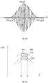
- the baseband input signal 113 can be one with a window function, e.g. a Tuckey window function, weighted baseband signal.
- the quantities ⁇ m and ⁇ denote the center frequency or the bandwidth of the signal.
- the Tuckey weighting is characterized by a good combination between frequency and time behavior. Typical bandwidths can be a few hundred MHz.
- the center frequency ⁇ m can be selected almost as desired by frequency conversion, but preferably in a range from 300 MHz to 300 GHz.
- the spectrum and time profile of the measurement signal 113 or 117 can be specified analytically.
- F. N ⁇ ⁇ 1 2 ⁇ 1 + cos 2 ⁇ ⁇ - ⁇ m ⁇ For ⁇ - ⁇ m ⁇ ⁇ ⁇ 2 0 otherwise
- FM chirps or multi-carrier signals (e.g. OFDM signals) can of course also be used.
- multi-carrier signals e.g. OFDM signals
- the signal generation unit 110 also has a high frequency carrier signal generation unit 114 which is designed to generate an RF carrier signal 115, for example in a frequency range from 300 MHz to 300 GHz to generate.
- the high-frequency carrier signal generation unit 114 can comprise an oscillator circuit.
- an up-conversion unit 116 is provided in the signal generation unit 110 for frequency conversion, which is designed to generate the broadband and band-limited RF input signal 117 for the RF filter 120 from the broadband and band-limited baseband input signal 113 and the RF carrier signal 115.
- the band-limited RF signal 117 obtained in this way can then be passed to the test arrangement with the RF filter 120 after appropriate conditioning (amplification, adaptation, possibly filtering, etc.).
- an electromagnetic field is created in the HF filter 120 and in its surroundings.
- the active ingredient units 102 passed along the filter surface influence this electromagnetic field in a characteristic manner for the active ingredient units and thus change a transmission characteristic of the HF filter 120, such as its amplitude response (magnitude frequency response) and / or phase response (phase frequency response).
- the changed transmission characteristic of the RF filter 120 as a measure e.g. the signal evaluation unit 130 can determine the mass and / or moisture of the active ingredient units 102.
- the signal 121 filtered by the test arrangement can also be received in the time domain.
- an optional down-mixer unit 136 is provided in the illustrated embodiment in order to generate an intermediate-frequency or baseband output signal 137 with manageable frequencies from the HF output signal 121 and the HF carrier signal 115 of the high-frequency carrier signal generation unit 114.
- the down-conversion unit 136 could also be dispensed with.
- the signal evaluation unit 130 is designed to determine from the baseband input signal (reference signal) 113 and the baseband output signal (received signal) 137 a transmission characteristic of the RF filter 120 as a measure for the characteristic variable (mass / moisture) of the active ingredient units 102.
- the two (analog) baseband signals 113 and 137 can be fed to an analog-to-digital converter (A / D converter) 132 before a digital signal processing unit 134, e.g. in the form of an FPGA, carries out digital signal processing of the resulting digital baseband signals.
- the signal evaluation unit 130 could also include a memory for the known baseband input signal (reference signal) 113. The desired information is obtained e.g. by dividing the received spectrum by the reference spectrum within the measurement bandwidth.
- the measurement bandwidth of the signal 113 or 117 can be several 100 MHz.
- the measurement time can easily be reduced to less than 1 ⁇ s with modern FPGAs.
- the digital signal processing unit 134 can use the digitized signals 113 and 137 to determine the transfer function H (f) of the filter 120 over a frequency range with a plurality of frequencies at short time intervals .
- These discrete values do not have to have recorded the precise point in time at which an active ingredient unit 102 was at the location of the highest measurement sensitivity. Therefore, from the discrete measured values and a known sensitivity curve of the HF filter 120, the maximum change in the transfer function can be calculated. This determined point of greatest influence on the transfer function can serve as a measure for the mass of the active ingredient units 102.
- a mass of an active ingredient unit 102 can be determined directly or indirectly as a characteristic variable based on the transfer characteristic determined during the interaction between the active ingredient unit 102 and the electromagnetic stray field and based on a reference transfer characteristic of the HF filter 120.
- This reference transfer characteristic can be calibrated beforehand with test specimens whose mass is precisely known. For example, a certain amount of a tablet type to be measured can first be precisely weighed out. The variations in the weights of the test tablets can be selected to be greater than the mass range in which the active ingredient units 102 later declared as “good” lie.
- Figure 2b shows schematically the course of a reference transmission characteristic 210 obtained by pre-calibration with known mass units in a frequency band from a lower frequency f u to an upper frequency f o . Furthermore, a tolerance range 220 with absolute lower and upper limits 222, 224 is shown.
- a transfer characteristic measured during the interaction between the active ingredient units 102 and the electromagnetic stray field can now be compared with the setpoint or reference transfer characteristic 210 applicable to the active ingredient unit 102. If the measured transfer characteristic deviates from the desired transfer characteristic 210 within the permissible tolerance range 220, an active ingredient unit 102 is released for further processing. Otherwise an error message will appear.
- the Fig. 3 shows a schematic flow diagram of a method 300 which can carry out the described measuring arrangement 100.
- the method 300 includes generating 310 an input signal 113, 117 for the RF filter 120.
- a baseband input signal 113 with a signal bandwidth of at least 10 MHz, at least 50 MHz, or at least 100 MHz can be used be generated.
- a carrier signal 115 can be generated in a frequency range of, for example, 300 MHz to 300 GHz.
- a broadband high-frequency input signal 117 for the filter 120 can then be generated from the baseband input signal 113 and the carrier signal 115.
- the method 300 further comprises producing 320 an interaction between at least one active substance unit 102 and a stray electromagnetic field of the HF filter 120 caused by the input signal 117.
- the at least one active substance unit 102 can be on the surface 122 of the HF filter 120 for an interaction between the electromagnetic stray field of the HF filter 120 and the at least one active ingredient unit 102, for example be passed by touching.
- the method 300 also includes determining 330 a transmission characteristic of the HF filter 120 as a measure for the characteristic variable from the input signal 113, 117 and an output signal 121, 137 of the HF filter 120.
- a baseband output signal 137 can be generated from the RF output signal 121 and the carrier signal 115, for example. From the baseband input signal 113 and the baseband output signal 137, a transmission characteristic of the RF filter 120 can be determined as a measure for the characteristic variable of the at least one active ingredient unit 102.
- the mass of the at least one active ingredient unit 102 can now be determined.
- the measured transfer characteristic can be compared with a reference transfer characteristic valid for the at least one active ingredient unit 102.
- This reference transmission characteristic can be calibrated in advance, for example. If a deviation of the measured transfer characteristic from the target transfer characteristic lies within a permissible tolerance range, the at least one active agent unit 102, e.g. one or more tablets released for further processing. Otherwise an error message can be issued.
- the transfer function can describe the transmission properties or the reflection properties of the test arrangement.
- the transmitted and received signals are compared with one another. This can be done, for example, by determining the respective spectra of the two signals 113 and 137 by Fourier transformation.
- the transfer function H (f) can be obtained by dividing the two spectra. In practice, the division is limited to the signal bandwidth in order to avoid division by 0.
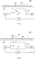
- the device 400 again comprises a signal generation unit 410, a high-frequency filter (RF filter) 420 coupled to the latter, and a signal evaluation unit 430 coupled therewith.
- the RF filter 420 has an input for an RF input signal 417 generated by the signal generation unit 410, an output for a filtered HF output signal 421 and a (closed or open) surface 422 for an interaction between an electromagnetic stray field of the HF filter 420 and the portioned active ingredient units 402.
- the output of the HF filter 420 is connected to an input of the signal evaluation unit 430.
- the signal generation unit 410 is designed to generate an input signal 417 for the RF filter 420.
- the input signal 417 can be a mono-frequency HF signal, for example the carrier signal 115, act.
- the signal evaluation unit 130 is designed to determine from the input signal 417 and the output signal 421 of the HF filter 420 a transmission characteristic in the form of a transit time difference between the signals 417 and 421 as a measure for the characteristic size of the portioned active ingredient units 102.
- a mass flow 402 is conducted past the HF filter 420.
- the measurement can again take place in a touching manner.
- the HF filter 420 can, for example, be built into a housing that is open on one side.
- the HF filter 420 can be mounted under the net and the measurement can be carried out through the net.
- a ceramic surface or the like can also be used instead of the open housing.
- the RF or microwave signal 417 is generated in the signal generation unit 410 and fed in parallel to the RF filter 420 and the signal evaluation unit 430.
- the phase difference between the filter output signal 421 and the input signal 417 can be formed by that of the signal generation unit 410.
- the frequency of the signal generation unit 410 or the input signal 417 generated by it can be readjusted via a suitably set controller 435 such that the frequency of the input signal 417 is at the maximum of the transfer function of the filter structure.
- the point of maximum slope of the measured curve for the phase difference can be used as a criterion for this.
- Fig. 5 a possible profile of the measured phase difference of the RF filter 420 can be seen.
- the frequency is plotted on the horizontal axis and the phase difference on the vertical axis.
- the curve shows a possible course of the phase difference with the point of greatest slope at 510.
- the mass flow 402 is passed through a sensor head 420 ', the measurement also takes place in a touching manner.
- the sensor head 420 ' comprises a suitably selected filter structure that can be built into a housing with a through opening.
- the measurement is carried out in the same way as the setup from Figure 4a .
- the mass is transported through a suitable pipe 440, for example.
- the Fig. 6 shows a schematic flow diagram of a method 600 which the measuring arrangement 400 can carry out.
- the method 600 comprises generating 610 an input signal 417 for the RF filter 420.
- an RF signal with a (discrete) frequency of e.g. 300 MHz to 300 GHz can be generated.
- the method 600 further comprises producing 620 an interaction between at least one active ingredient unit 402 and a stray electromagnetic field of the RF filter 420 caused by the input signal 417.
- the at least one active ingredient unit 402 on the surface 422 of the RF filter 420 for an interaction between the electromagnetic stray field of the HF filter 420 and the at least one active ingredient unit 102 for example be passed by touching.
- the method 600 also includes determining 630 a transmission characteristic of the RF filter 420 as a measure for the characteristic variable based on the input signal 417 and an output signal 421 of the RF filter 420.
- a transmission characteristic of the RF filter 420 as a measure for the characteristic variable based on the input signal 417 and an output signal 421 of the RF filter 420.
- the phases of the RF signals 417 and 421, or the Phases of signals derived therefrom The greater the influence of the mass flow 402 on the signal transit time through the filter 420, the greater the phase difference will turn out as a characteristic measure for the mass flow 402.
- embodiments of the present invention relate to a concept for measuring the mass and / or moisture of tablets or other portioned solid units by contact measurement with a high-frequency filter structure.
- the tablets or portioned solid units can be guided over the surface of a high-frequency filter at high speed.
- the presence of materials in the area of the stray field causes a changed phase shift and / or changed attenuation of the signal chain.
- This change in the transfer function of the high-frequency filter or the signal propagation time through the filter caused by the mass flow can be used to deduce the mass and / or the moisture content of the tablets or other portioned solid units.
- the transfer function of several signal components of a certain amplitude and frequency, that is to say a broadband signal, are modulated onto a high-frequency carrier, the frequency of which is in the pass band of the filter.
- the modulated carrier is passed through the filter and then demodulated and the resulting signals digitized.
- the transfer function of the high-frequency filter can be calculated from the digitized signals by digital signal processing. Both the modulation and the digital signal processing can take place with such a high bandwidth, for example 200 MHz, that the mechanical movement of the tablets or the portioned solid units is very slow in comparison. This means that even at very high transport speeds through the field of the high-frequency filter, a tablet or portioned solid unit is measured several times.
- the presence of material in the area of the stray field causes a change in the transit time through the high-frequency filter structure.
- the signal is fed to a detector through the filter structure from the generator and the signal is fed directly from the signal generation unit as a reference. This signal does not need to be broadband here.
- the detector evaluates a phase difference between the two signals.
- the signal frequency of the signal generation unit can now be readjusted via a suitably set controller so that the frequency lies at the point of the maximum slope of the measured curve for the phase difference.
- the frequency of the signal supplied by the generator is now a measure of the sum of the dielectric properties of the substance to be measured. Since the frequency can be measured very precisely, a high level of measurement accuracy is achieved. By appropriately dimensioning the controller, a high measurement speed can also be achieved.
- a major advantage here is the high sensitivity and thus high measurement accuracy.
- aspects have been described in connection with a device, it goes without saying that these aspects also represent a description of the corresponding method, so that a block or a component of a device is also to be understood as a corresponding method step or as a feature of a method step. Analogously, aspects that have been described in connection with or as a method step also represent a description of a corresponding block or details or features of a corresponding device.
- exemplary embodiments of the present invention can be implemented in hardware or in software.
- the implementation can be carried out using a digital storage medium such as a floppy disk, a DVD, a Blu-Ray disk, a CD, a ROM, a PROM, an EPROM, an EEPROM or a FLASH memory, a hard disk or other magnetic memory or optical memory, on which electronically readable control signals are stored, which can interact or cooperate with a programmable hardware component in such a way that the respective method is carried out.
- a digital storage medium such as a floppy disk, a DVD, a Blu-Ray disk, a CD, a ROM, a PROM, an EPROM, an EEPROM or a FLASH memory, a hard disk or other magnetic memory or optical memory, on which electronically readable control signals are stored, which can interact or cooperate with a programmable hardware component in such a way that the respective method is carried out.
- the digital storage medium can therefore be machine or computer readable.
- Some exemplary embodiments thus include a data carrier that has electronically readable control signals that are able to interact with a programmable computer system or a programmable hardware component in such a way that one of the methods described herein is carried out.
- An embodiment is thus a data carrier (or a digital storage medium or a computer-readable medium) on which the program for performing one of the methods described herein is recorded.
- embodiments of the present invention can be implemented as a program, firmware, computer program or computer program product with a program code or as data, wherein the program code or the data is effective or are to carry out one of the methods when the program is on a processor or a programmable hardware component runs.
- the program code or the data can, for example, also be stored on a machine-readable carrier or data carrier.
- the program code or the data can be present as source code, machine code or bytecode, as well as other intermediate code, among other things.
- a program can implement one of the methods while it is being carried out, for example, by reading out memory locations or writing data or several data into them, which may result in switching operations or other operations in transistor structures, in amplifier structures or in other electrical, optical, magnetic or components working according to another functional principle. Accordingly, data, values, sensor values or other information can be recorded, determined or measured by a program by reading out a memory location.
- a program can therefore acquire, determine or measure quantities, values, measured quantities and other information by reading out one or more memory locations, and by writing to one or more memory locations it can cause, initiate or carry out an action and control other devices, machines and components .
Description
Ausführungsbeispiele der vorliegenden Erfindung betreffen allgemein Vorrichtungen und Verfahren zur Ermittlung von für ein Objekt charakteristischen Größen, wie beispielsweise eine Masse und/oder einen Feuchtigkeitsgehalt des Objekts.Embodiments of the present invention generally relate to devices and methods for determining variables characteristic of an object, such as a mass and / or a moisture content of the object.
Derartige Verfahren und/oder Vorrichtungen können beispielsweise in der industriellen Massenproduktion von Medikamenten eingesetzt werden. In diesem Fall dienen portionierte Medikamente, beispielsweise in Form von Tabletten, als Objekt. Selbstverständlich sind auch weitere Einsatzgebiete möglich, bei denen es auf hohe Geschwindigkeiten bei der Bestimmung von für ein Objekt charakteristischen Größen ankommt.Such methods and / or devices can be used, for example, in the industrial mass production of drugs. In this case, portioned drugs, for example in the form of tablets, serve as the object. Of course, other areas of application are also possible in which high speeds are important when determining variables that are characteristic of an object.
Tabletten bleiben auf absehbare Zeit die wichtigste Darreichungsform von Medikamenten. Die Anforderungen an deren Produktion steigen zusehends deutlich an: Erhöhter Wettbewerb und Kostendruck haben das Thema Effizienz in den Vordergrund gerückt. Die Produktion neuartiger, komplexer Präparate muss entsprechend qualitätsorientiert und effizient erfolgen - und das bei einer steigenden Zahl von Produktionswechseln. High-Speed-Tablettierung mit einem Ausstoß von mehr als 1,6 Millionen Tabletten pro Stunde sind derzeit die Maßstäbe für Produktivität in der Tablettierung. Gleichzeitig müssen Pharmaproduzenten an allen Standorten hohe Qualitätsstandards sicherstellen, um die Richtlinien der Kontrollbehörden zu erfüllen. Dies macht eine 100% Produktkontrolle erforderlich. Daraus resultieren als Anforderung an Messsysteme sehr hohe Messgeschwindigkeiten, bei gleichzeitig möglichst geringem ober besser keinem Einfluss auf den Massestromtransport.Tablets will remain the most important form of drug delivery for the foreseeable future. The demands on their production are increasing noticeably: Increased competition and cost pressure have brought the issue of efficiency to the fore. The production of new, complex preparations must be accordingly quality-oriented and efficient - and that with an increasing number of production changes. High-speed tableting with an output of more than 1.6 million tablets per hour is currently the benchmark for productivity in tableting. At the same time, pharmaceutical manufacturers must ensure high quality standards at all locations in order to meet the guidelines of the control authorities. This makes a 100% product inspection necessary. This results in very high measuring speeds as a requirement for measuring systems, with at the same time the least possible or, better still, no influence on the mass flow transport.
Bisherige Produktkontrollen erfolgen oft durch mechanische Wiegesysteme. Ein mechanischer Wiegevorgang benötigt allerdings eine gewisse Zeit, um einen Messwert einschwingen zulassen. Diese Zeit kann nicht beliebig verkürzt werden. Man kann dem Problem z.B. durch eine große Anzahl von parallel angeordneten Einrichtungen für die Verwiegung teilweise begegnen. Dadurch werden das Messsystem und die Tablettenzuführung aber sehr umfangreich, teuer und störanfällig. Die einzelnen Tabletten müssen zudem aus dem kontinuierlichen Transportstrom mechanisch entnommen und auf einem Wiegegutaufnehmer positioniert werden. Außerdem ist durch die empfindliche mechanische Führung bei derartigen Waagen bei Änderung des Formates der zu wiegenden Wirkstoffeinheiten ein erheblicher mechanischer Umbau von Produktführungen erforderlich.Previous product controls were often carried out using mechanical weighing systems. A mechanical weighing process, however, requires a certain amount of time to allow a measured value to settle. This time cannot be shortened arbitrarily. The problem can be partially countered, for example, by a large number of weighing devices arranged in parallel. This makes the measuring system and the tablet feed very extensive, expensive and prone to failure. The individual tablets also have to be removed mechanically from the continuous transport flow and positioned on a weighed goods pick-up. Besides, by the delicate mechanical Guidance in such scales when changing the format of the active ingredient units to be weighed requires a considerable mechanical conversion of product guides.
Es gibt verschiedene Ansätze, um die obigen Nachteile, die vor allem durch die Trägheit der Wiegetechnik hervorgerufen werden, durch kapazitive Messtechniken zu überwinden. Derartige Ansätze werden beispielsweise in
Die
Es kann als eine Aufgabe von Ausführungsbeispielen der vorliegenden Erfindung betrachtet werden, den vorbekannten Stand der Technik betreffend die Bestimmung einer für ein Objekt charakteristischen Größe, wie z.B. dessen Masse, weiterzubilden.It can be regarded as an object of exemplary embodiments of the present invention to further develop the known prior art relating to the determination of a variable that is characteristic of an object, such as its mass, for example.
Dem wird durch Vorrichtungen und Verfahren mit den Merkmalen der unabhängigen Patentansprüche Rechnung getragen. Vorteilhafte Ausgestaltungen und Weiterbildungen sind Gegenstand der abhängigen Ansprüche.This is taken into account by devices and methods with the features of the independent patent claims. Advantageous refinements and developments are the subject of the dependent claims.
Gemäß einem ersten Aspekt schaffen Ausführungsbeispiele eine Vorrichtung zur Ermittlung einer für ein Objekt charakteristischen Größe. Die Vorrichtung umfasst dazu eine Signalerzeugungseinheit, die ausgebildet ist, um ein Eingangssignal zu erzeugen. Ferner umfasst die Vorrichtung ein Hochfrequenzfilter mit einem Eingang für das Eingangssignal, einem Ausgang für ein Ausgangssignal und mit einem Bereich, z.B. einer Oberfläche, für eine Wechselwirkung zwischen einem elektromagnetischen Streufeld des Hochfrequenzfilters und dem Objekt. Außerdem ist eine Signalauswerteeinheit vorgesehen, die ausgebildet ist, um aus dem Eingangssignal und dem Ausgangssignal des Hochfrequenzfilters eine Übertragungscharakteristik des Hochfrequenzfilters als Maß für die charakteristische Größe des Objekts zu ermitteln.According to a first aspect, exemplary embodiments create a device for determining a variable that is characteristic of an object. To this end, the device comprises a signal generation unit which is designed to generate an input signal. The device further comprises a high-frequency filter with an input for the input signal, an output for an output signal and with an area, for example a surface, for an interaction between an electromagnetic stray field of the high-frequency filter and the object. In addition, a signal evaluation unit is provided which is designed to convert the input signal and the output signal of the High frequency filter to determine a transmission characteristic of the high frequency filter as a measure for the characteristic size of the object.
Gemäß Ausführungsbeispielen kann die Übertragungscharakteristik eine Übertragungsfunktion des Hochfrequenzfilters und/oder eine Signallaufzeit durch das Hochfrequenzfilter umfassen.According to exemplary embodiments, the transfer characteristic can include a transfer function of the high-frequency filter and / or a signal propagation time through the high-frequency filter.
Ausführungsbeispiele basieren somit auf dem Gedanken, die charakteristische Größe des Objekts aus einer für das Objekt charakteristischen Beeinflussung der Übertragungscharakteristik des Hochfrequenzfilters zu ermitteln. Während der Wechselwirkung zwischen Objekt und elektromagnetischem Streufeld befindet sich das Objekt gemäß manchen Ausführungsbeispielen an bzw. unmittelbar auf einer Oberfläche des Hochfrequenzfilters. Letzteres kann beispielsweise als Hohlraum- oder Koaxialresonator ausgebildet sein. Die Oberfläche des Filters für die Wechselwirkung mit dem Messobjekt kann beispielsweise eine für elektromagnetische Strahlung möglichst transparente Seite eines Filtergehäuses, wie z.B. eine Keramikfläche oder ein anderes geeignetes Material umfassen.Embodiments are therefore based on the idea of determining the characteristic size of the object from an influencing of the transmission characteristic of the high-frequency filter that is characteristic of the object. During the interaction between the object and the stray electromagnetic field, according to some exemplary embodiments, the object is located on or directly on a surface of the high-frequency filter. The latter can be designed, for example, as a cavity or coaxial resonator. The surface of the filter for interaction with the measurement object can, for example, be a side of a filter housing that is as transparent as possible for electromagnetic radiation, e.g. comprise a ceramic surface or other suitable material.
Gemäß manchen Ausführungsbeispielen kann zusätzlich eine Transporteinrichtung vorgesehen sein, die ausgebildet ist, um das Objekt an der Oberfläche des Hochfrequenzfilters entlangzuführen. Beispiele für Transporteinrichtungen sind Rohre oder Rinnen, in denen das Objekt mit vergleichsweise hoher Geschwindigkeit an der Oberfläche des Hochfrequenzfilters vorbeigeführt werden kann, um kurzzeitig mit dessen elektromagnetischem Streufeld in Wechselwirkung zu treten. Dabei kann die Filteroberfläche einen Teil der Transporteinrichtung, z.B. eine Rohr- oder Rinnenwand, bilden. Somit können hohe Massestromtransportgeschwindigkeiten, also hohe Produktionsgeschwindigkeiten erzielt werden. Andere Beispiele für Transporteinrichtungen umfassen auch Förderbänder oder dergleichen.According to some exemplary embodiments, a transport device can additionally be provided which is designed to guide the object along the surface of the high-frequency filter. Examples of transport devices are pipes or channels in which the object can be guided past the surface of the high-frequency filter at a comparatively high speed in order to briefly interact with its stray electromagnetic field. The filter surface can be part of the transport device, e.g. form a pipe or gutter wall. High mass flow transport speeds, that is to say high production speeds, can thus be achieved. Other examples of transport devices also include conveyor belts or the like.
Bevorzugt ist die Transporteinrichtung ausgebildet, um das Objekt die Oberfläche unmittelbar berührend entlang der Oberfläche des Hochfrequenzfilters zu bewegen. Das Objekt steht während der Messung also in berührendem Kontakt mit der Oberfläche des Filters, indem es beispielsweise darauf abrollt oder darüber geschoben wird. Durch die Berührung können besonders exakte Messergebnisse für die charakteristische Größe erzielt werden.The transport device is preferably designed to move the object along the surface of the high-frequency filter in direct contact with the surface. During the measurement, the object is in touching contact with the surface of the filter, for example by rolling over it or being pushed over it. By touching it, particularly precise measurement results can be achieved for the characteristic variable.
Bei manchen Ausführungsbeispielen kann die charakteristische Größe eine Masse und/oder Feuchte des Objekts umfassen. Von der durch das Objekt veränderten Übertragungscharakteristik des Hochfrequenzfilters kann also auf die Masse und/oder Feuchte des vorbeigeführten Objekts geschlossen werden. Andere charakteristische Größen, wie z.B. Größe, Form, etc., sind selbstverständlich ebenfalls denkbar.In some exemplary embodiments, the characteristic variable can include a mass and / or moisture content of the object. From the transmission characteristic of the high-frequency filter changed by the object, conclusions can be drawn about the mass and / or moisture of the object being passed. Other characteristic quantities, e.g. Size, shape, etc. are of course also conceivable.
Das Objekt selbst kann gemäß manchen Ausführungsbeispielen wenigstens eine portionierte Feststoffeinheit, wie z.B. eine Tablette, eine Kapsel, etc., umfassen. Somit können Ausführungsbeispiele die Effizienz von Medikamentenproduktion erhöhen.According to some exemplary embodiments, the object itself can contain at least one portioned solid unit, e.g. a tablet, a capsule, etc. Thus, embodiments can increase the efficiency of drug production.
Bei einigen Ausführungsformen kann die Signalauswerteeinheit ausgebildet sein, um die Übertragungscharakteristik durch eine Ermittlung einer Laufzeit- bzw. Phasendifferenz zwischen dem Eingangssignal und dem Ausgangssignal zu bestimmen. Die Phasendifferenz kann dann als Maß für charakteristische Größe des Objekts herangezogen werden. Dies kann vorteilhaft zu hohen Empfindlichkeiten und damit hohe Messgenauigkeiten führen.In some embodiments, the signal evaluation unit can be designed to determine the transmission characteristic by ascertaining a transit time or phase difference between the input signal and the output signal. The phase difference can then be used as a measure for the characteristic size of the object. This can advantageously lead to high sensitivities and thus high measuring accuracies.
Gemäß manchen Ausführungsbeispielen ist die Signalerzeugungseinheit ausgebildet, um das Eingangssignal mit einer (Träger-) Frequenz in einem Frequenzbereich von 300 MHz bis 300 GHz bereitzustellen. Dabei kann es sich je nach Ausführungsform um ein monofrequentes oder um ein breitbandiges Eingangssignal handeln.According to some exemplary embodiments, the signal generation unit is designed to provide the input signal with a (carrier) frequency in a frequency range from 300 MHz to 300 GHz. Depending on the embodiment, this can be a mono-frequency or a broadband input signal.
Im letzteren Fall kann die Signalerzeugungseinheit ausgebildet sein, um das Eingangssignal für das Hochfrequenzfilter durch Mischen eines Basisbandeingangssignals mit einem hochfrequenten Trägersignal im Durchlassbereich des Hochfrequenzfilters zu erzeugen. Das Hochfrequenzfilter kann also als Bandpass ausgebildet sein. Insbesondere kann die Signalerzeugungseinheit ausgebildet sein, um das Trägersignal mit einer Trägerfrequenz in einem Frequenzbereich von 300 MHz bis 300 GHz bereitzustellen. Dabei kann die Trägerfrequenz beispielsweise abhängig von einer Signalbandbreite des Basisbandeingangssignals gewählt werden - je größer dessen Bandbreite, desto höher die Trägerfrequenz.In the latter case, the signal generation unit can be designed to generate the input signal for the high-frequency filter by mixing a baseband input signal with a high-frequency carrier signal in the pass band of the high-frequency filter. The high-frequency filter can therefore be designed as a band pass. In particular, the signal generation unit can be designed to provide the carrier signal with a carrier frequency in a frequency range from 300 MHz to 300 GHz. The carrier frequency can for example be selected as a function of a signal bandwidth of the baseband input signal - the larger its bandwidth, the higher the carrier frequency.
Bei manchen Ausführungsbeispielen ist die Signalerzeugungseinheit ausgebildet, um das Basisbandeingangssignal mit einer Signalbandbreite von wenigstens 10 MHz zu erzeugen. Es handelt sich hier also nicht nur um ein Trägersignal mit einer diskreten Trägerfrequenz, sondern um ein vergleichsweise breitbandiges auf die Trägerfrequenz auf moduliertes Signal. Durch den daraus resultierenden und eine Mehrzahl von Frequenzen umfassenden Spektralbereich der Übertragungscharakteristik kann eine hohe Messgenauigkeit erreicht werden. Es können Amplituden- und/oder Phasengang für die ganze Signalbandbreite oder einen Teil davon, umfassend eine Mehrzahl von Frequenzen, als Objektcharakteristikum ausgewertet werden.In some exemplary embodiments, the signal generation unit is designed to generate the baseband input signal with a signal bandwidth of at least 10 MHz produce. This is not just a carrier signal with a discrete carrier frequency, but a comparatively broadband signal modulated onto the carrier frequency. The resulting spectral range of the transmission characteristic, which encompasses a plurality of frequencies, enables a high level of measurement accuracy to be achieved. The amplitude and / or phase response for the entire signal bandwidth or a part thereof, including a plurality of frequencies, can be evaluated as an object characteristic.
Beispielsweise kann bei Ausführungsbeispielen eine sogenannte Multicarrier-Modulation, insbesondere ein orthogonales Frequenzmultiplexverfahren (OFDM = Orthogonal Frequency-Division Multiplexing), zum Einsatz kommen. Bereits bei dem breitbandigen Basisbandeingangssignal kann es sich also um ein OFDM Signal im Basisband handeln. Selbstverständlich kommen auch andere geeignete Basisbandsignale in Frage, wie z.B. Pseudo-Zufallssequenzen.For example, what is known as multicarrier modulation, in particular an orthogonal frequency division multiplexing method (OFDM = orthogonal frequency division multiplexing), can be used in exemplary embodiments. The broadband baseband input signal can already be an OFDM signal in the baseband. Of course, other suitable baseband signals are also possible, e.g. Pseudo-random sequences.
Zur Bandbegrenzung des Eingangssignals kann die Signalerzeugungseinheit ausgebildet sein, um das Basisbandeingangssignal mittels einer Fensterfunktion, insbesondere einer Tuckey-Fensterfunktion, zu gewichten. Selbstverständlich können auch andere geeignete Fensterfunktionen zur Bandbegrenzung eingesetzt werden.In order to limit the band of the input signal, the signal generation unit can be designed to weight the baseband input signal by means of a window function, in particular a Tuckey window function. Of course, other suitable window functions can also be used to limit the band.
Betreffend den Ausgang des Hochfrequenzfilters kann die Signalauswerteeinheit ausgebildet sein, um durch Mischen des Ausgangssignals mit dem Trägersignal ein Basisbandausgangssignal zu erzeugen und, um aus dem Basisbandeingangssignal und dem Basisbandausgangssignal die Übertragungscharakteristik zu ermitteln. Durch die Ermittlung der Übertragungscharakteristik im Basisbandbereich kann auf aufwändige und kostspielige HF-Schaltungsanordnungen verzichtet werden.With regard to the output of the high-frequency filter, the signal evaluation unit can be designed to generate a baseband output signal by mixing the output signal with the carrier signal and to determine the transmission characteristic from the baseband input signal and the baseband output signal. By determining the transmission characteristics in the baseband range, complex and costly RF circuit arrangements can be dispensed with.
Insbesondere kann die Signalauswerteeinheit ausgebildet sein, um die Übertragungscharakteristik durch Division des Basisbandausgangs- und des Basisbandeingangssignals oder deren jeweiligen Frequenzspektren zu ermitteln. Alternativ oder zusätzlich kann die Signalauswerteeinheit ausgebildet sein, um die Übertragungscharakteristik durch einen Phasenvergleich zwischen Basisbandausgangs- und des Basisbandeingangssignal zu ermitteln. Dies kann beispielsweise mittels eines Digitalen Signal Prozessors (DSP) oder eines Field Programmable Gate Arrays (FPGA) implementiert werden.In particular, the signal evaluation unit can be designed to determine the transmission characteristic by dividing the baseband output signal and the baseband input signal or their respective frequency spectra. Alternatively or additionally, the signal evaluation unit can be designed to determine the transmission characteristic by a phase comparison between the baseband output signal and the baseband input signal. This can be implemented, for example, by means of a digital signal processor (DSP) or a field programmable gate array (FPGA).
Gemäß manchen Ausführungsbeispielen kann die Signalauswerteeinheit ausgebildet sein, um die Übertragungscharakteristik mit einer für das Objekt vorbestimmten Referenzübertragungscharakteristik zu vergleichen und eine Fehlermeldung auszugeben, wenn ein Unterschied zwischen der Übertragungscharakteristik und der Referenzübertragungscharakteristik oberhalb eines Schwellenwerts liegt. Damit ist eine effiziente Aussortierung von fehlerhaften Objekt möglich.According to some exemplary embodiments, the signal evaluation unit can be designed to compare the transmission characteristic with a reference transmission characteristic predetermined for the object and to output an error message if a difference between the transmission characteristic and the reference transmission characteristic is above a threshold value. This enables faulty objects to be sorted out efficiently.
Gemäß einem weiteren Aspekt schaffen Ausführungsbeispiele eine Vorrichtung zur Ermittlung einer für wenigstens eine Tablette charakteristischen Größe. Die Vorrichtung umfasst eine Basisbandsignalerzeugungseinheit, die ausgebildet ist, um ein Basisbandeingangssignal mit einer Signalbandbreite von wenigstens 10 MHz zu erzeugen, eine Hochfrequenzträgersignalerzeugungseinheit, die ausgebildet ist, um ein Trägersignal in einem Frequenzbereich von 300 MHz bis 300 GHz zu erzeugen, eine Mischereinheit, die ausgebildet ist, um aus dem Basisbandeingangssignal und dem Trägersignal Hochfrequenzeingangssignal zu erzeugen und ein Hochfrequenzfilter mit einem Eingang für das Hochfrequenzeingangssignal, einem Ausgang für ein Hochfrequenzausgangssignal und mit einer Filteroberfläche. Ferner ist eine Transporteinrichtung vorgesehen, die ausgebildet ist, um die wenigstens eine Tablette an der Oberfläche des Hochfrequenzfilters für eine Wechselwirkung zwischen einem elektromagnetischen Streufeld des Hochfrequenzfilters und der wenigstens eine Tablette vorbeizuführen. Die Mischereinheit ist ausgebildet, um aus dem Hochfrequenzausgangssignal und dem Trägersignal ein Basisbandausgangssignal zu erzeugen. Die Vorrichtung umfasst auch eine Signalauswerteeinheit, die ausgebildet ist, um aus dem Basisbandeingangssignal und dem Basisbandausgangssignal eine eine Mehrzahl von Frequenzen umfassende Übertragungscharakteristik des Hochfrequenzfilters als Maß für die charakteristische Größe der wenigstens einen Tablette ermitteln.According to a further aspect, embodiments create a device for determining a variable that is characteristic of at least one tablet. The device comprises a baseband signal generation unit which is designed to generate a baseband input signal with a signal bandwidth of at least 10 MHz, a high-frequency carrier signal generation unit which is designed to generate a carrier signal in a frequency range from 300 MHz to 300 GHz, a mixer unit which is designed is to generate from the baseband input signal and the carrier signal high frequency input signal and a high frequency filter with an input for the high frequency input signal, an output for a high frequency output signal and with a filter surface. Furthermore, a transport device is provided which is designed to move the at least one tablet past the surface of the high-frequency filter for an interaction between an electromagnetic stray field of the high-frequency filter and the at least one tablet. The mixer unit is designed to generate a baseband output signal from the high-frequency output signal and the carrier signal. The device also comprises a signal evaluation unit, which is designed to determine from the baseband input signal and the baseband output signal a transmission characteristic of the high-frequency filter comprising a plurality of frequencies as a measure for the characteristic size of the at least one tablet.
Gemäß einem noch weiteren Aspekt schaffen Ausführungsbeispiele Verfahren zur Ermittlung einer für ein Objekt charakteristischen Größe. Das Verfahren umfasst ein Erzeugen eines Eingangssignals für ein Hochfrequenzfilter; ein Herstellen einer Wechselwirkung zwischen dem Objekt und einem durch das Eingangssignal hervorgerufenen elektromagnetischen Streufeld des Hochfrequenzfilters, und ein Ermitteln, aus dem Eingangssignal und einem Ausgangssignal des Hochfrequenzfilters, einer Übertragungscharakteristik des Hochfrequenzfilters als Maß für die charakteristische Größe.According to yet another aspect, exemplary embodiments create methods for determining a variable that is characteristic of an object. The method comprises generating an input signal for a high frequency filter; producing an interaction between the object and a stray electromagnetic field of the high-frequency filter caused by the input signal, and determining, from the input signal and an output signal of the high-frequency filter, a transmission characteristic of the high-frequency filter as a measure of the characteristic variable.
Gemäß manchen Ausführungsbeispielen umfasst das Herstellen der Wechselwirkung ein Bewegen des Objekts entlang der Oberfläche des Hochfrequenzfilters, insbesondere ein berührendes Bewegen.According to some exemplary embodiments, establishing the interaction includes moving the object along the surface of the high-frequency filter, in particular moving it in a touching manner.
Gemäß manchen Ausführungsbeispielen kann die Übertragungscharakteristik durch eine Bestimmung einer Laufzeit- bzw. Phasendifferenz zwischen dem Eingangssignal und dem Ausgangssignal ermittelt werden. Ergänzend oder alternativ kann die Übertragungscharakteristik durch Bestimmen einer Übertragungsfunktion für einen Frequenzbereich umfassend eine Mehrzahl von Frequenzen ermittelt werden.According to some exemplary embodiments, the transmission characteristic can be determined by determining a transit time or phase difference between the input signal and the output signal. Additionally or alternatively, the transfer characteristic can be determined by determining a transfer function for a frequency range comprising a plurality of frequencies.
Als charakteristische Größe kann gemäß manchen Ausführungsbeispielen eine Masse des Objekts bestimmt werden basierend auf der während der Wechselwirkung zwischen dem Objekt und dem elektromagnetischen Streufeld ermittelten Übertragungscharakteristik und basierend auf einer Referenzübertragungscharakteristik des Hochfrequenzfilters ohne Wechselwirkung zwischen dem Objekt und dem elektromagnetischen Streufeld des Hochfrequenzfilters.According to some exemplary embodiments, a mass of the object can be determined as a characteristic variable based on the transmission characteristic determined during the interaction between the object and the stray electromagnetic field and based on a reference transmission characteristic of the high-frequency filter without interaction between the object and the stray electromagnetic field of the high-frequency filter.
Bei anderen Ausführungsformen kann die während der Wechselwirkung zwischen dem Objekt und dem elektromagnetischen Streufeld ermittelte Übertragungscharakteristik mit einem Vergleich mit einer für das Objekt bzw. die Art des Objekts geltenden Soll-Übertragungscharakteristik (oder Referenzübertragungscharakteristik) verglichen werden. Liegt eine Abweichung der gemessenen Übertragungscharakteristik von der Soll-Übertragungscharakteristik innerhalb eines zulässigen Toleranzbereichs, wird das Objekt, z.B. ein oder mehrere Tabletten, zur Weiterverarbeitung freigegeben. Anderenfalls erfolgt eine Fehlermeldung.In other embodiments, the transmission characteristic determined during the interaction between the object and the stray electromagnetic field can be compared with a comparison with a setpoint transmission characteristic (or reference transmission characteristic) that applies to the object or the type of object. If a deviation of the measured transfer characteristic from the target transfer characteristic lies within a permissible tolerance range, the object, e.g. one or more tablets released for further processing. Otherwise an error message will appear.
Vorteile von Ausführungsbeispielen können darin gesehen werden, dass diese leicht in bestehende Transportvorrichtungen von Tablettenpressen eingefügt werden können. Es braucht keine technisch aufwendige und den Transportstrom verzögernde Einzelpositionierung von Prüfkörpern vorgenommen werden. Weiter erlaubt der vorgeschlagene Ansatz mit einer schnellen digitalen Signalverarbeitung sehr hohe Messraten zu realisieren.Advantages of exemplary embodiments can be seen in the fact that they can easily be inserted into existing transport devices of tablet presses. There is no need for any technically complex and individual positioning of test bodies that would delay the transport stream. Furthermore, the proposed approach allows very high measurement rates to be achieved with fast digital signal processing.
Einige beispielhafte Ausführungsbeispiele der vorliegenden Erfindung werden nachfolgend bezugnehmend auf die beiliegenden Figuren näher erläutert. Es zeigen:
- Fig. 1
- ein Blockdiagram einer Vorrichtung zur Ermittlung einer Masse und/oder Feuchte wenigstens einer Tablette;
- Fig. 2a
- Tuckey-Fensterfunktion zur Bandbegrenzung;
- Fig. 2b
- einen Verlauf einer durch Kalibrierung erhaltenen Referenzübertragungscharakteristik;
- Fig. 3
- ein schematisches Flussdiagramm eines möglichen Verfahrens zur Ermittlung einer Masse und/oder Feuchte wenigstens einer Tablette;
- Fig. 4a,b
- Blockdiagramme von Vorrichtungen zur Ermittlung einer Masse und/oder Feuchte wenigstens einer Tablette;
- Fig. 5
- Verlauf einer gemessenen Phasendifferenz aufgetragen über Frequenz; und
- Fig. 6
- ein schematisches Flussdiagramm eines weiteren möglichen Verfahrens zur Ermittlung einer Masse und/oder Feuchte wenigstens einer Tablette.
- Fig. 1
- a block diagram of a device for determining a mass and / or moisture content of at least one tablet;
- Fig. 2a
- Tuckey window function for band limitation;
- Figure 2b
- a course of a reference transmission characteristic obtained by calibration;
- Fig. 3
- a schematic flow diagram of a possible method for determining a mass and / or moisture of at least one tablet;
- Figures 4a, b
- Block diagrams of devices for determining a mass and / or moisture of at least one tablet;
- Fig. 5
- Course of a measured phase difference plotted against frequency; and
- Fig. 6
- a schematic flow diagram of a further possible method for determining a mass and / or moisture of at least one tablet.
Verschiedene Ausführungsbeispiele werden nun ausführlicher unter Bezugnahme auf die beiliegenden Zeichnungen beschrieben, in denen einige Ausführungsbeispiele dargestellt sind. In den Figuren können die Dickenabmessungen von Linien, Schichten und/oder Regionen um der Deutlichkeit Willen übertrieben dargestellt sein.Various embodiments will now be described more fully with reference to the accompanying drawings, in which some embodiments are shown. In the figures, the thickness dimensions of lines, layers and / or regions may be exaggerated for the sake of clarity.
Bei der nachfolgenden Beschreibung der beigefügten Figuren, die lediglich einige exemplarische Ausführungsbeispiele zeigen, können gleiche Bezugszeichen gleiche oder vergleichbare Komponenten bezeichnen. Ferner können zusammenfassende Bezugszeichen für Komponenten und Objekte verwendet werden, die mehrfach in einem Ausführungsbeispiel oder in einer Zeichnung auftreten, jedoch hinsichtlich eines oder mehrerer Merkmale gemeinsam beschrieben werden. Komponenten oder Objekte, die mit gleichen oder zusammenfassenden Bezugszeichen beschrieben werden, können hinsichtlich einzelner, mehrerer oder aller Merkmale, beispielsweise ihrer Dimensionierungen, gleich, jedoch gegebenenfalls auch unterschiedlich ausgeführt sein, sofern sich aus der Beschreibung nicht etwas anderes explizit oder implizit ergibt.In the following description of the attached figures, which only show a few exemplary embodiments, the same reference symbols can designate the same or comparable components. Furthermore, summarizing reference symbols can be used for components and objects that appear several times in an exemplary embodiment or in a drawing, but are described jointly with regard to one or more features. Components or objects that are described with the same or combined reference symbols can with regard to individual, several or all features, for example their dimensions, the same, but possibly also different, unless something else explicitly or implicitly results from the description.
Obwohl Ausführungsbeispiele auf verschiedene Weise modifiziert und abgeändert werden können, sind Ausführungsbeispiele in den Figuren als Beispiele dargestellt und werden hierin ausführlich beschrieben. Es sei jedoch klargestellt, dass nicht beabsichtigt ist, Ausführungsbeispiele auf die jeweils offenbarten Formen zu beschränken, sondern dass Ausführungsbeispiele vielmehr sämtliche funktionale und/oder strukturelle Modifikationen, Äquivalente und Alternativen, die im Bereich der Erfindung liegen, abdecken sollen. Gleiche Bezugszeichen bezeichnen in der gesamten Figurenbeschreibung gleiche oder ähnliche Elemente.Although exemplary embodiments can be modified and changed in various ways, exemplary embodiments are shown in the figures as examples and are described in detail herein. It should be made clear, however, that the intention is not to restrict exemplary embodiments to the respectively disclosed forms, but rather that exemplary embodiments are intended to cover all functional and / or structural modifications, equivalents and alternatives that are within the scope of the invention. The same reference symbols denote the same or similar elements throughout the description of the figures.
Man beachte, dass ein Element, das als mit einem anderen Element "verbunden" oder "verkoppelt" bezeichnet wird, mit dem anderen Element direkt verbunden oder verkoppelt sein kann oder dass dazwischenliegende Elemente vorhanden sein können. Wenn ein Element dagegen als "direkt verbunden" oder "direkt verkoppelt" mit einem anderen Element bezeichnet wird, sind keine dazwischenliegenden Elemente vorhanden. Andere Begriffe, die verwendet werden, um die Beziehung zwischen Elementen zu beschreiben, sollten auf ähnliche Weise interpretiert werden (z.B., "zwischen" gegenüber "direkt dazwischen", "angrenzend" gegenüber "direkt angrenzend" usw.).It should be noted that an element referred to as being "connected" or "coupled" to another element may be directly connected or coupled to the other element, or intervening elements may be present. Conversely, when an element is referred to as being "directly connected" or "directly coupled" to another element, there are no intervening elements. Other terms used to describe the relationship between elements should be interpreted in a similar manner (e.g., "between" versus "directly between", "adjacent" versus "directly adjacent", etc.).
Die Terminologie, die hierin verwendet wird, dient nur der Beschreibung bestimmter Ausführungsbeispiele und soll die Ausführungsbeispiele nicht beschränken. Wie hierin verwendet, sollen die Singularformen "einer," "eine", "eines" und "der, die, das" auch die Pluralformen beinhalten, solange der Kontext nicht eindeutig etwas anderes angibt. Ferner sei klargestellt, dass die Ausdrücke wie z.B. "beinhaltet", "beinhaltend", aufweist" und/oder "aufweisend", wie hierin verwendet, das Vorhandensein von genannten Merkmalen, ganzen Zahlen, Schritten, Arbeitsabläufen, Elementen und/oder Komponenten angeben, aber das Vorhandensein oder die Hinzufügung von einem bzw. einer oder mehreren Merkmalen, ganzen Zahlen, Schritten, Arbeitsabläufen, Elementen, Komponenten und/oder Gruppen davon nicht ausschließen.The terminology used herein is only used to describe particular exemplary embodiments and is not intended to limit the exemplary embodiments. As used herein, the singular forms "a," "an," "an," and "the" are intended to include the plural forms as well, unless the context clearly indicates otherwise. It should also be made clear that the expressions such as e.g. "includes", "including", "has" and / or "having" as used herein indicate the presence of named features, integers, steps, workflows, elements and / or components, but the presence or addition of one or more Do not exclude one or more features, integers, steps, workflows, elements, components and / or groups thereof.
Solange nichts anderes definiert ist, haben sämtliche hierin verwendeten Begriffe (einschließlich von technischen und wissenschaftlichen Begriffen) die gleiche Bedeutung, die ihnen ein Durchschnittsfachmann auf dem Gebiet, zu dem die Ausführungsbeispiele gehören, beimisst. Ferner sei klargestellt, dass Ausdrücke, z.B. diejenigen, die in allgemein verwendeten Wörterbüchern definiert sind, so zu interpretieren sind, als hätten sie die Bedeutung, die mit ihrer Bedeutung im Kontext der einschlägigen Technik konsistent ist, und nicht in einem idealisierten oder übermäßig formalen Sinn zu interpretieren sind, solange dies hierin nicht ausdrücklich definiert ist.Unless otherwise defined, all terms used herein (including technical and scientific terms) have the same meaning, which one of ordinary skill in the art to which the embodiments pertain will attach to them. It should also be clarified that terms, such as those defined in commonly used dictionaries, are to be interpreted as having a meaning consistent with their meaning in the context of the relevant technology and not in an idealized or overly formal sense are to be interpreted unless expressly defined herein.
Die
Die Vorrichtung 100 umfasst eine Signalerzeugungseinheit 110, ein mit letzterer gekoppeltes Hochfrequenzfilter (HF-Filter) 120 und eine wiederum damit gekoppelte Signalauswerteeinheit 130. Das HF-Filter 120 hat einen Eingang für ein von der Signalerzeugungseinheit 110 erzeugtes HF-Eingangssignal 117, einen Ausgang für ein aus dem HF-Eingangssignal 117 gefiltertes HF-Ausgangssignal 121 und eine Oberfläche 122 für eine Wechselwirkung zwischen einem elektromagnetischen Streufeld des HF-Filters 120 und den portionierten Wirkstoffeinheiten 102. Der Ausgang des HF-Filters 120 ist mit einem Eingang der Signalauswerteeinheit 130 verbindbar bzw. verbunden.The
In dem gezeigten Ausführungsbeispiel werden die portionierten Wirkstoffeinheiten 102 mittels einer Transporteinrichtung 140 mit möglichst hoher Geschwindigkeit berührend entlang der Filteroberfläche 122 geführt. In anderen Worten stehen Wirkstoffeinheiten 102 und Filteroberfläche 122 bei der Messung also in Berührung miteinander. Die Transporteinrichtung 140 kann beispielsweise ein Förderband, eine Transportrinne, ein Transportrohr oder dergleichen umfassen, um die Wirkstoffeinheiten 102 in unmittelbaren Kontakt mit der Filteroberfläche bzw. Filtergehäuseoberfläche 122 zu bringen.In the exemplary embodiment shown, the portioned
Das HF-Filter 120, welches als Bandpassfilter ausgebildet ist, kann beispielsweise als Hohlraum- oder Koaxialresonator implementiert sein. Es kann für eine Mittenfrequenz des HF-Eingangssignals 117 in z.B. einem Bereich von 300 MHz bis 300 GHz ausgelegt sein. Sein Durchlassbereich um die Mittenfrequenz ist entsprechend einer Bandbreite des HF-Eingangssignals 117 beispielsweise wenigstens 10 MHz, wenigstens 50 MHz, oder wenigstens 100 MHz. Die Filteroberfläche 122 kann beispielsweise als Keramikoberfläche ausgelegt sein und Teil einer Transportröhre oder -rinne sein, mittels der die Wirkstoffeinheiten 102 an dem HF-Filter 120 für die Messung berührend vorbeigeführt werden. Das HF-Filter 120 kann so konstruiert sein, dass ein Teil des elektrischen Feldes das zu messende Material durchdringen kann. Dafür kann ein umgebendes Filtergehäuse einseitig offen sein oder eine Durchgangsöffnung aufweisen.The
Die Signalerzeugungseinheit 110 ist gemäß dem hier gezeigten Ausführungsbeispiel ausgebildet, um das HF-Eingangssignal 117 für das HF-Filter 120 aus einem Basisbandeingangssignal 113 mit Tiefpassverhalten zu erzeugen. Dazu umfasst die Signalerzeugungseinheit 110 eine Basisbandsignalerzeugungseinheit 112, die ausgebildet ist, um das Basisbandeingangssignal 113 mit einer Signalbandbreite von wenigstens 10 MHz, wenigstens 50 MHz, oder wenigstens 100 MHz zu erzeugen. An dieser Stelle sei angemerkt, dass die Signalbandbreite abhängig von der Geschwindigkeit der Wirkstoffeinheiten 102 gewählt werden kann. Je schneller sich die Wirkstoffeinheiten 102 bewegen, desto größer sollte die Bandbreite gewählt werden. Umgekehrt kann bei langsamer Bewegung die Signalbandbreite kleiner ausfallen. Die Basisbandsignalerzeugungseinheit 112 kann in manchen Ausführungsformen Digital-Analog Wandler (D/A-Wandler) aufweisen, um aus einem digitalen Basisbandsignal ein analoges Basisbandsignal zu erzeugen.According to the exemplary embodiment shown here, the
Die Basisbandsignalerzeugungseinheit 112 kann zur Erzeugung des Basisbandeingangssignals 113 beispielsweise eine oder mehrere programmierbare Hardwarekomponenten wie DSPs, ASICs, oder FPGAs umfassen. Bei dem Basisbandeingangssignal 113 kann es sich gemäß manchen Ausführungsbeispielen um ein mit einer Fensterfunktion, z.B. einer Tuckey-Fensterfunktion, gewichtetes Basisbandsignal handeln.The baseband
Dazu zeigt
Für diesen speziellen Fall kann Spektrum und Zeitverlauf des Messsignals 113 bzw. 117 analytisch angegeben werden. 
Die zugeordnete Zeitbereichsfunktion FN (t) lässt sich leicht durch eine inverse Fourier-Transformation berechnen: 
Alternative Breitbandsignale wie FM-Chirps oder Mehrträgersignale (z.B. OFDM-Signale) können natürlich ebenfalls verwendet werden.Alternative broadband signals such as FM chirps or multi-carrier signals (e.g. OFDM signals) can of course also be used.
Um aus dem Basisbandeingangssignal 113 das HF-Eingangssignal 117 mit der Mitten- bzw. Trägerfrequenz ωm zu erhalten, weist die Signalerzeugungseinheit 110 außerdem eine Hochfrequenzträgersignalerzeugungseinheit 114 auf, die ausgebildet ist, um ein HF-Trägersignal 115 z.B. in einem Frequenzbereich von 300 MHz bis 300 GHz zu erzeugen. Dazu kann die Hochfrequenzträgersignalerzeugungseinheit 114 eine Oszillatorschaltung umfassen. Ferner ist in der Signalerzeugungseinheit 110 zur Frequenzumsetzung eine Aufwärtsmischereinheit 116 vorgesehen, die ausgebildet ist, um aus dem breitbandigen und bandbegrenzten Basisbandeingangssignal 113 und dem HF-Trägersignal 115 das breitbandige und bandbegrenzte HF-Eingangssignal 117 für das HF-Filter 120 zu erzeugen. Das so erhaltene bandbegrenzte HF-Signal 117 kann dann nach entsprechender Konditionierung (Verstärkung, Anpassung, ggf. Filterung, etc.) auf die Testanordnung mit dem HF-Filter 120 gegeben werden.In order to obtain the
Durch Speisen des HF-Filters 120 mit dem HF-Eingangssignal 117 entsteht in dem HF-Filter 120 und in dessen Umgebung ein elektromagnetisches Feld. Die entlang der Filteroberfläche vorbeigeführten Wirkstoffeinheiten 102 beeinflussen dieses elektromagnetische Feld für die Wirkstoffeinheiten charakteristisch und verändern damit eine Übertragungscharakteristik des HF-Filters 120, wie z.B. dessen Amplitudengang (Betragsfrequenzgang) und/oder Phasengang (Phasenfrequenzgang).By feeding the
Die veränderte Übertragungscharakteristik des HF-Filters 120 als Maß z.B. für die Masse und/oder Feuchte der Wirkstoffeinheiten 102 kann von der Signalauswerteeinheit 130 ermittelt werden. Auch der Empfang des durch die Testanordnung gefilterten Signals 121 kann im Zeitbereich erfolgen. Dazu ist in dem dargestellten Ausführungsbeispiel eine optionale Abwärtsmischereinheit 136 vorgesehen, um aus dem HF-Ausgangssignal 121 und dem HF-Trägersignal 115 der Hochfrequenzträgersignalerzeugungseinheit 114 ein Zwischenfrequenz- oder Basisbandausgangssignal 137 mit handhabbaren Frequenzen zu erzeugen. Mit entsprechend schnellen Digital Wandlern (A/D-Wandlern) 132 könnte auf die Abwärtsmischereinheit 136 auch verzichtet werden.The changed transmission characteristic of the
Die Signalauswerteeinheit 130 ist in dem dargestellten Beispiel ausgebildet, um aus dem Basisbandeingangssignal (Referenzsignal) 113 und dem Basisbandausgangssignal (Empfangssignal) 137 eine Übertragungscharakteristik des HF-Filters 120 als Maß für die charakteristische Größe (Masse/Feuchte) der Wirkstoffeinheiten 102 zu ermitteln. Dazu können in manchen Ausführungsbeispielen einem Analog-Digital Wandler (A/D-Wandler) 132 die beiden (analogen) Basisbandsignale 113 und 137 zugeführt werden, bevor eine digitale Signalverarbeitungseinheit 134, z.B. in Form eines FPGA, eine digitale Signalverarbeitung der resultierenden digitalen Basisbandsignale vornimmt. In anderen Ausführungsformen könnte die Signalauswerteeinheit 130 aber auch einen Speicher für das bekannte Basisbandeingangssignal (Referenzsignal) 113 umfassen. Die gewünschte Information erhält man z.B. durch Division von Empfangsspektrum durch Referenzspektrum innerhalb der Messbandbreite.In the example shown, the
Mit modernen A/D-Wandlern sind Abtastraten bis über 1 GSample/sec. möglich. Entsprechend kann die Messbandbreite des Signals 113 bzw. 117 mehrere 100 MHz betragen. Die Messdauer kann mit modernen FPGAs leicht auf unter 1µs reduziert werden.With modern A / D converters, sampling rates of over 1 GSample / sec. possible. Correspondingly, the measurement bandwidth of the
Während der Bewegung der Wirkstoffeinheiten 102 entlang der Oberfläche des HF-Filters 120 kann von der digitalen Signalverarbeitungseinheit 134 mittels der digitalisierten Signale 113 und 137 in kurzen zeitlichen Abständen die Übertragungsfunktion H(f) des Filters 120 über einen Frequenzbereich mit einer Mehrzahl von Frequenzen bestimmt werden. Diese diskreten Werte müssen nicht den genauen Zeitpunkt erfasst haben, an dem sich eine Wirkstoffeinheit 102 am Ort der höchsten Messempfindlichkeit befand. Deshalb kann aus den diskreten Messwerten und einem bekannten Empfindlichkeitsverlauf des HF-Filters 120 die maximale Veränderung der Übertragungsfunktion errechnet werden. Dieser ermittelte Punkt der größten Beeinflussung der Übertragungsfunktion kann als Maß für die Masse der Wirkstoffeinheiten 102 dienen.During the movement of the
Als charakteristische Größe kann gemäß manchen Ausführungsbeispielen direkt oder indirekt eine Masse einer Wirkstoffeinheit 102 bestimmt werden basierend auf der während der Wechselwirkung zwischen der Wirkstoffeinheit 102 und dem elektromagnetischen Streufeld ermittelten Übertragungscharakteristik und basierend auf einer Referenzübertragungscharakteristik des HF-Filters 120. Diese Referenzübertragungscharakteristik kann vorab durch Kalibrierung mit Probeköpern, deren Masse genau bekannt ist, erhalten werden. Zum Beispiel kann dazu eine bestimmte Menge von einem zu messenden Tablettentyp zuerst genau ausgewogen werden. Die Variationen der Gewichte der Testtabletten können dabei größer gewählt werden als der Massebereich in dem die später als "gut" deklarierten Wirkstoffeinheiten 102 liegen.According to some exemplary embodiments, a mass of an
Während der Produktion kann nun eine während der Wechselwirkung zwischen den Wirkstoffeinheiten 102 und dem elektromagnetischen Streufeld gemessene Übertragungscharakteristik mit der für die Wirkstoffeinheit 102 geltenden Soll- bzw. Referenzübertragungscharakteristik 210 verglichen werden. Liegt eine Abweichung der gemessenen Übertragungscharakteristik von der Soll-Übertragungscharakteristik 210 innerhalb des zulässigen Toleranzbereichs 220, wird eine Wirkstoffeinheit 102 zur Weiterverarbeitung freigegeben. Anderenfalls erfolgt eine Fehlermeldung.During production, a transfer characteristic measured during the interaction between the
Die
Das Verfahren 300 umfasst ein Erzeugen 310 eines Eingangssignals 113, 117 für das HF-Filter 120. Dazu kann zunächst ein Basisbandeingangssignal 113 mit einer Signalbandbreite von wenigstens 10 MHz, wenigstens 50 MHz, oder wenigstens 100 MHz erzeugt werden. Ferner kann ein Trägersignal 115 in einem Frequenzbereich von z.B. 300 MHz bis 300 GHz erzeugt werden. Aus dem Basisbandeingangssignal 113 und dem Trägersignal 115 kann anschließend ein breitbandiges Hochfrequenzeingangssignal 117 für das Filter 120 erzeugt werden.The
Das Verfahren 300 umfasst ferner ein Herstellen 320 einer Wechselwirkung zwischen wenigstens einer Wirkstoffeinheit 102 und einem durch das Eingangssignal 117 hervorgerufenen elektromagnetischen Streufeld des HF-Filters 120. Dazu kann die wenigstens eine Wirkstoffeinheit 102 an der Oberfläche 122 des HF-Filters 120 für eine Wechselwirkung zwischen dem elektromagnetischen Streufeld des HF-Filters 120 und der wenigstens einen Wirkstoffeinheit 102 z.B. berührend vorbeigeführt werden.The
Das Verfahren 300 weist zudem ein Ermitteln 330 einer Übertragungscharakteristik des HF-Filters 120 als Maß für die charakteristische Größe aus dem Eingangssignal 113, 117 und einem Ausgangssignal 121, 137 des HF-Filters 120 auf. Dazu kann beispielsweise aus dem HF-Ausgangssignal 121 und dem Trägersignal 115 ein Basisbandausgangssignal 137 erzeugt werden. Aus dem Basisbandeingangssignal 113 und dem Basisbandausgangssignal 137 kann eine Übertragungscharakteristik des HF-Filters 120 als Maß für die charakteristische Größe der wenigstens einen Wirkstoffeinheit 102 ermittelt werden.The
Basierend auf der während der Wechselwirkung zwischen dem Objekt und dem elektromagnetischen Streufeld ermittelten Übertragungscharakteristik und basierend auf einer Referenzübertragungscharakteristik des Hochfrequenzfilters kann nun die Masse der wenigstens einen Wirkstoffeinheit 102 ermittelt werden. Dazu kann die gemessene Übertragungscharakteristik mit einer für die wenigstens eine Wirkstoffeinheit 102 geltende Referenzübertragungscharakteristik verglichen werden. Diese Referenzübertragungscharakteristik kann beispielsweise vorab einkalibirert werden. Liegt eine Abweichung der gemessenen Übertragungscharakteristik von der Soll-Übertragungscharakteristik innerhalb eines zulässigen Toleranzbereichs, wird die wenigstens eine Wirkstoffeinheit 102, z.B. ein oder mehrere Tabletten, zur Weiterverarbeitung freigegeben. Anderenfalls kann eine Fehlermeldung ausgegeben werden.Based on the transmission characteristic determined during the interaction between the object and the stray electromagnetic field and based on a reference transmission characteristic of the high-frequency filter, the mass of the at least one
Die Messung der Übertragungsfunktion H(f) des HF-Filters 120 kann konventionell mit einem Netzwerkanalysator erfolgen, wobei nacheinander bei verschiedenen diskreten Frequenzpunkten Betrag und Phase der interessierenden Übertragungsfunktion aufgenommen werden. Als Anregung werden monofrequente Signale (cw = continuous wave) benützt. Die Übertragungsfunktion kann die Transmissionseigenschaften oder die Reflexionseigenschaften der Testanordnung beschreiben.The measurement of the transfer function H (f) of the
Für sehr schnelle Vorgänge, wie der Medikamentenproduktion, ist es allerdings zu langwierig, die Übertragungsfunktion H(f) nacheinander bei verschiedenen Frequenzen zu messen. Hier bietet sich die systemtheoretische gleichwertige Messung im Zeitbereich an, was sich Ausführungsbeispiele der vorliegenden Erfindung zunutze machen. Systeme werden im Zeitbereich durch ihre Impulsantwort beschrieben. Dazu werden kurze trägerfrequente (d.h. auf den Träger 115 aufmodulierte) Pulse verwendet. Sie belegen eine wohldefinierte von Null verschiedene Bandbreite und erzeugen ein ebenso wohldefiniertes Spektrum.For very fast processes, such as drug production, however, it is too time-consuming to measure the transfer function H (f) one after the other at different frequencies. The system-theoretical equivalent measurement in the time domain offers itself here, which exemplary embodiments of the present invention make use of. Systems are described in the time domain by their impulse response. For this purpose, short carrier-frequency (i.e. modulated onto carrier 115) pulses are used. They occupy a well-defined bandwidth different from zero and generate an equally well-defined spectrum.
Zur Ermittlung des Einflusses der Wirkstoffeinheiten 102 werden Sende- und Empfangssignal miteinander verglichen. Dies kann zum Beispiel durch Ermittlung der jeweiligen Spektren der beiden Signale 113 und 137 durch Fourier-Transformation erfolgen. Die Übertragungsfunktion H(f) kann durch Division der beiden Spektren erhalten werden. In der Praxis beschränkt man hierbei die Division auf die Signalbandbreite, um Division durch 0 zu vermeiden.To determine the influence of the
Weitere mögliche Vergleichsbeispiele werden nun anhand der
Die Vorrichtung 400 umfasst wieder eine Signalerzeugungseinheit 410, ein mit letzterer gekoppeltes Hochfrequenzfilter (HF-Filter) 420 und eine wiederum damit gekoppelte Signalauswerteeinheit 430. Das HF-Filter 420 hat einen Eingang für ein von der Signalerzeugungseinheit 410 erzeugtes HF-Eingangssignal 417, einen Ausgang für ein gefiltertes HF-Ausgangssignal 421 und eine (geschlossene oder offene) Oberfläche 422 für eine Wechselwirkung zwischen einem elektromagnetischen Streufeld des HF-Filters 420 und den portionierten Wirkstoffeinheiten 402. Der Ausgang des HF-Filters 420 ist mit einem Eingang der Signalauswerteeinheit 430 verbunden.The
Die Signalerzeugungseinheit 410 ist ausgebildet, um ein Eingangssignal 417 für das HF-Filter 420 zu erzeugen. Im Gegensatz zur Ausführungsform der
Im Aufbau nach
Das HF- bzw. Mikrowellensignal 417 wird in der Signalerzeugungseinheit 410 erzeugt und parallel dem HF-Filter 420 und der Signalauswerteeinheit 430 zugeführt. In der Signalauswerteeinheit 430 kann die Phasendifferenz zwischen dem Filterausgangssignal 421 und dem Eingangssignal 417 von der der Signalerzeugungseinheit 410 gebildet werden. Über einen passend eingestellten Regler 435 kann die Frequenz der Signalerzeugungseinheit 410 bzw. des von diesem erzeugten Eingangssignals 417 so nachgeregelt werden, dass die Frequenz des Eingangssignals 417 im Maximum der Übertragungsfunktion der Filterstruktur liegt. Als Kriterium hierfür kann die Stelle maximaler Steigung der gemessenen Kurve für die Phasendifferenz herangezogen werden.The RF or
In
Im alternativen Aufbau nach
Die
Das Verfahren 600 umfasst ein Erzeugen 610 eines Eingangssignals 417 für das HF-Filter 420. Dazu kann ein HF-Signal mit einer (diskreten) Frequenz von z.B. 300 MHz bis 300 GHz erzeugt werden.The method 600 comprises generating 610 an
Das Verfahren 600 umfasst ferner ein Herstellen 620 einer Wechselwirkung zwischen wenigstens einer Wirkstoffeinheit 402 und einem durch das Eingangssignal 417 hervorgerufenen elektromagnetischen Streufeld des HF-Filters 420. Dazu kann die wenigstens eine Wirkstoffeinheit 402 an der Oberfläche 422 des HF-Filters 420 für eine Wechselwirkung zwischen dem elektromagnetischen Streufeld des HF-Filters 420 und der wenigstens einen Wirkstoffeinheit 102 z.B. berührend vorbeigeführt werden.The method 600 further comprises producing 620 an interaction between at least one
Das Verfahren 600 weist zudem ein Ermitteln 630 einer Übertragungscharakteristik des HF-Filters 420 als Maß für die charakteristische Größe basierend auf dem Eingangssignal 417 und einem Ausgangssignal 421 des HF-Filters 420. Dazu können die Phasen der HF-Signale 417 und 421, oder die Phasen von daraus abgeleiteten Signalen, verglichen werden. Je größer der Einfluss des Massestroms 402 auf die Signallaufzeit durch das Filter 420, desto größer wird der Phasenunterschied als charakteristisches Maß für den Massestrom 402 ausfallen.The method 600 also includes determining 630 a transmission characteristic of the
Zusammenfassend betreffen Ausführungsbeispiele der vorliegenden Erfindung ein Konzept zum Messen der Masse und/oder Feuchte von Tabletten oder anderen portionierten Feststoffeinheiten durch berührende Messung mit einer Hochfrequenzfilterstruktur. Dabei können die Tabletten oder portionierten Feststoffeinheiten mit hoher Geschwindigkeit über die Oberfläche eines Hochfrequenzfilters geführt werden. Das Vorhandensein von Materialen im Bereich des Streufeldes bewirkt eine veränderte Phasenverschiebung und/oder veränderte Bedämpfung der Signalkette.In summary, embodiments of the present invention relate to a concept for measuring the mass and / or moisture of tablets or other portioned solid units by contact measurement with a high-frequency filter structure. The tablets or portioned solid units can be guided over the surface of a high-frequency filter at high speed. The presence of materials in the area of the stray field causes a changed phase shift and / or changed attenuation of the signal chain.
Aus dieser durch den Massenstrom hervorgerufenen Veränderung der Übertragungsfunktion des Hochfrequenzfilters bzw. der Signallaufzeit durch das Filter kann auf die Masse und/oder den Feuchtigkeitsgehalt der Tabletten oder anderen portionierten Feststoffeinheiten geschlossen werden.This change in the transfer function of the high-frequency filter or the signal propagation time through the filter caused by the mass flow can be used to deduce the mass and / or the moisture content of the tablets or other portioned solid units.
Zur Bestimmung der Übertragungsfunktion werden gemäß einem Aspekt auf einen hochfrequenten Träger, dessen Frequenz im Durchlassbereich des Filters liegt, mehrere Signaleanteile bestimmter Amplitude und Frequenz, also ein Breitbandsignal, aufmoduliert. Der modulierte Träger wird durch das Filter geleitet und anschließend demoduliert und die resultierenden Signale digitalisiert. Aus den digitalisierten Signalen kann die Übertragungsfunktion des Hochfrequenzfilters durch digitale Signalverarbeitung berechnet werden. Sowohl die Modulation und als auch die digitale Signalverarbeitung können mit so hoher Bandbreite, beispielsweise 200 MHz, erfolgen, dass die mechanische Bewegung der Tabletten bzw. der portionierten Feststoffeinheiten im Vergleich dazu sehr langsam ist. Das heißt, auch bei sehr hohen Transportgeschwindigkeiten durch das Feld des Hochfrequenzfilters wird eine Tablette bzw. portionierte Feststoffeinheit mehrfach vermessen. Mit der Kenntnis der Feldverteilung des Hochfrequenzfilters können für jede Tablettenform bzw. portionierte Feststoffeinheit und jede Transportgeschwindigkeit die genauen relevanten Messwerte errechnet werden. Ein großer Vorteil dieses Messverfahren besteht darin, dass in sehr kurzer Zeit die Übertragungsfunktion der Messanordnung über einen ganzen Frequenzbereich ermittelt werden kann.To determine the transfer function, according to one aspect, several signal components of a certain amplitude and frequency, that is to say a broadband signal, are modulated onto a high-frequency carrier, the frequency of which is in the pass band of the filter. The modulated carrier is passed through the filter and then demodulated and the resulting signals digitized. The transfer function of the high-frequency filter can be calculated from the digitized signals by digital signal processing. Both the modulation and the digital signal processing can take place with such a high bandwidth, for example 200 MHz, that the mechanical movement of the tablets or the portioned solid units is very slow in comparison. This means that even at very high transport speeds through the field of the high-frequency filter, a tablet or portioned solid unit is measured several times. With the knowledge of the field distribution of the high-frequency filter, the precise relevant measured values can be calculated for each tablet shape or portioned solid unit and each transport speed. A great advantage of this measuring method is that the transfer function of the measuring arrangement can be determined over an entire frequency range in a very short time.
Gemäß einem weiteren Aspekt bewirkt das Vorhandensein von Material im Bereich des Streufeldes eine Veränderung der Laufzeit durch die Hochfrequenzfilterstruktur. Einem Detektor wird das Signal durch die Filterstruktur vom Generator und als Referenz das Signal direkt von der Signalerzeugungseinheit zugeführt. Dieses Signal braucht hier nicht breitbandig zu sein. Der Detektor wertet eine Phasendifferenz zwischen den beiden Signalen aus. Über einen passend eingestellten Regler kann die Signalfrequenz der Signalerzeugungseinheit jetzt so nachgeregelt werden, dass die Frequenz im Punkt der maximalen Steigung der gemessenen Kurve für die Phasendifferenz liegt. Die Frequenz des vom Generator gelieferten Signals ist nun ein Maß für die Summe der dielektrischen Eigenschaften des zu messenden Stoffes. Da die Frequenz sehr genau zu messen ist, erreicht man eine hohe Messgenauigkeit. Durch passende Dimensionierung des Reglers ist zusätzlich eine hohe Messgeschwindigkeit erreichbar. Ein wesentlicher Vorteil hier ist die hohe Empfindlichkeit und damit hohe Messgenauigkeit.According to a further aspect, the presence of material in the area of the stray field causes a change in the transit time through the high-frequency filter structure. The signal is fed to a detector through the filter structure from the generator and the signal is fed directly from the signal generation unit as a reference. This signal does not need to be broadband here. The detector evaluates a phase difference between the two signals. The signal frequency of the signal generation unit can now be readjusted via a suitably set controller so that the frequency lies at the point of the maximum slope of the measured curve for the phase difference. The frequency of the signal supplied by the generator is now a measure of the sum of the dielectric properties of the substance to be measured. Since the frequency can be measured very precisely, a high level of measurement accuracy is achieved. By appropriately dimensioning the controller, a high measurement speed can also be achieved. A major advantage here is the high sensitivity and thus high measurement accuracy.
Die in der vorstehenden Beschreibung, den nachfolgenden Ansprüchen und den beigefügten Figuren offenbarten Merkmale können sowohl einzeln wie auch in beliebiger Kombination für die Verwirklichung eines Ausführungsbeispiels in ihren verschiedenen Ausgestaltungen von Bedeutung sein und implementiert werden.The features disclosed in the above description, the following claims and the attached figures can be used individually or in any desired way Combination can be important and implemented for the implementation of an exemplary embodiment in its various configurations.
Obwohl manche Aspekte im Zusammenhang mit einer Vorrichtung beschrieben wurden, versteht es sich, dass diese Aspekte auch eine Beschreibung des entsprechenden Verfahrens darstellen, sodass ein Block oder ein Bauelement einer Vorrichtung auch als ein entsprechender Verfahrensschritt oder als ein Merkmal eines Verfahrensschrittes zu verstehen ist. Analog dazu stellen Aspekte, die im Zusammenhang mit einem oder als ein Verfahrensschritt beschrieben wurden, auch eine Beschreibung eines entsprechenden Blocks oder Details oder Merkmals einer entsprechenden Vorrichtung dar.Although some aspects have been described in connection with a device, it goes without saying that these aspects also represent a description of the corresponding method, so that a block or a component of a device is also to be understood as a corresponding method step or as a feature of a method step. Analogously, aspects that have been described in connection with or as a method step also represent a description of a corresponding block or details or features of a corresponding device.
Je nach bestimmten Implementierungsanforderungen können Ausführungsbeispiele der vorliegenden Erfindung, zumindest Teile davon, in Hardware oder in Software implementiert sein. Die Implementierung kann unter Verwendung eines digitalen Speichermediums, beispielsweise einer Floppy-Disk, einer DVD, einer Blu-Ray Disc, einer CD, eines ROM, eines PROM, eines EPROM, eines EEPROM oder eines FLASH-Speichers, einer Festplatte oder eines anderen magnetischen oder optischen Speichers durchgeführt werden, auf dem elektronisch lesbare Steuersignale gespeichert sind, die mit einer programmierbaren Hardwarekomponente derart zusammenwirken können oder zusammenwirken, dass das jeweilige Verfahren durchgeführt wird.Depending on specific implementation requirements, exemplary embodiments of the present invention, at least parts thereof, can be implemented in hardware or in software. The implementation can be carried out using a digital storage medium such as a floppy disk, a DVD, a Blu-Ray disk, a CD, a ROM, a PROM, an EPROM, an EEPROM or a FLASH memory, a hard disk or other magnetic memory or optical memory, on which electronically readable control signals are stored, which can interact or cooperate with a programmable hardware component in such a way that the respective method is carried out.
Eine programmierbare Hardwarekomponente kann durch einen Prozessor, einen Computerprozessor (CPU = Central Processing Unit), einen Grafikprozessor (GPU = Graphics Processing Unit), einen Computer, ein Computersystem, einen anwendungsspezifischen integrierten Schaltkreis (ASIC = Application-Specific Integrated Circuit), einen integrierten Schaltkreis (IC = Integrated Circuit), ein Ein-Chip-System (SOC = System on Chip), ein programmierbares Logikelement oder ein feldprogrammierbares Gatterarray mit einem Mikroprozessor (FPGA = Field Programmable Gate Array) gebildet sein.A programmable hardware component can be a processor, a computer processor (CPU = Central Processing Unit), a graphics processor (GPU = Graphics Processing Unit), a computer, a computer system, an application-specific integrated circuit (ASIC = Application-Specific Integrated Circuit), an integrated Circuit (IC = Integrated Circuit), a one-chip system (SOC = System on Chip), a programmable logic element or a field-programmable gate array with a microprocessor (FPGA = Field Programmable Gate Array).
Das digitale Speichermedium kann daher maschinen- oder computerlesbar sein. Manche Ausführungsbeispiele umfassen also einen Datenträger, der elektronisch lesbare Steuersignale aufweist, die in der Lage sind, mit einem programmierbaren Computersystem oder einer programmierbare Hardwarekomponente derart zusammenzuwirken, dass eines der hierin beschriebenen Verfahren durchgeführt wird. Ein Ausführungsbeispiel ist somit ein Datenträger (oder ein digitales Speichermedium oder ein computerlesbares Medium), auf dem das Programm zum Durchführen eines der hierin beschriebenen Verfahren aufgezeichnet ist.The digital storage medium can therefore be machine or computer readable. Some exemplary embodiments thus include a data carrier that has electronically readable control signals that are able to interact with a programmable computer system or a programmable hardware component in such a way that one of the methods described herein is carried out. An embodiment is thus a data carrier (or a digital storage medium or a computer-readable medium) on which the program for performing one of the methods described herein is recorded.
Allgemein können Ausführungsbeispiele der vorliegenden Erfindung als Programm, Firmware, Computerprogramm oder Computerprogrammprodukt mit einem Programmcode oder als Daten implementiert sein, wobei der Programmcode oder die Daten dahin gehend wirksam ist bzw. sind, eines der Verfahren durchzuführen, wenn das Programm auf einem Prozessor oder einer programmierbaren Hardwarekomponente abläuft. Der Programmcode oder die Daten kann bzw. können beispielsweise auch auf einem maschinenlesbaren Träger oder Datenträger gespeichert sein. Der Programmcode oder die Daten können unter anderem als Quellcode, Maschinencode oder Bytecode sowie als anderer Zwischencode vorliegen.In general, embodiments of the present invention can be implemented as a program, firmware, computer program or computer program product with a program code or as data, wherein the program code or the data is effective or are to carry out one of the methods when the program is on a processor or a programmable hardware component runs. The program code or the data can, for example, also be stored on a machine-readable carrier or data carrier. The program code or the data can be present as source code, machine code or bytecode, as well as other intermediate code, among other things.
Ein Programm gemäß einem Ausführungsbeispiel kann eines der Verfahren während seiner Durchführung beispielsweise dadurch umsetzen, dass dieses Speicherstellen ausliest oder in diese ein Datum oder mehrere Daten hinein schreibt, wodurch gegebenenfalls Schaltvorgänge oder andere Vorgänge in Transistorstrukturen, in Verstärkerstrukturen oder in anderen elektrischen, optischen, magnetischen oder nach einem anderen Funktionsprinzip arbeitenden Bauteile hervorgerufen werden. Entsprechend können durch ein Auslesen einer Speicherstelle Daten, Werte, Sensorwerte oder andere Informationen von einem Programm erfasst, bestimmt oder gemessen werden. Ein Programm kann daher durch ein Auslesen von einer oder mehreren Speicherstellen Größen, Werte, Messgrößen und andere Informationen erfassen, bestimmen oder messen, sowie durch ein Schreiben in eine oder mehrere Speicherstellen eine Aktion bewirken, veranlassen oder durchführen sowie andere Geräte, Maschinen und Komponenten ansteuern.A program according to an embodiment can implement one of the methods while it is being carried out, for example, by reading out memory locations or writing data or several data into them, which may result in switching operations or other operations in transistor structures, in amplifier structures or in other electrical, optical, magnetic or components working according to another functional principle. Accordingly, data, values, sensor values or other information can be recorded, determined or measured by a program by reading out a memory location. A program can therefore acquire, determine or measure quantities, values, measured quantities and other information by reading out one or more memory locations, and by writing to one or more memory locations it can cause, initiate or carry out an action and control other devices, machines and components .
Die oben beschriebenen Ausführungsbeispiele stellen lediglich eine Veranschaulichung der Prinzipien der vorliegenden Erfindung dar. Es versteht sich, dass Modifikationen und Variationen der hierin beschriebenen Anordnungen und Einzelheiten anderen Fachleuten einleuchten werden. Deshalb ist beabsichtigt, dass die Erfindung lediglich durch den Schutzumfang der nachstehenden Patentansprüche und nicht durch die spezifischen Einzelheiten, die anhand der Beschreibung und der Erläuterung der Ausführungsbeispiele hierin präsentiert wurden, beschränkt sei.The above-described embodiments are merely illustrative of the principles of the present invention. It is to be understood that modifications and variations of the arrangements and details described herein will be apparent to other skilled persons. It is therefore intended that the invention be limited only by the scope of protection of the following patent claims and not by the specific details presented herein with reference to the description and explanation of the exemplary embodiments.
Claims (11)
- An apparatus (100) for determining a variable characteristic of an object (102) comprising:a signal generation unit (110) configured to generate an input signal (113; 117);a high-frequency filter (120) with an input for the input signal (113; 117;), an output for an output signal (121; 137), and with a region (122) for an interaction between an electromagnetic stray field of the high-frequency filter (120) and the object (102); anda signal evaluation unit (130) configured to use the input signal (113; 117) and the output signal (121; 137) of the high-frequency filter to determine a transmission characteristic of the high-frequency filter as a measure for the characteristic size of the object (102),characterized in thatthe signal generation unit (110) is configured to generate the input signal (117) by mixing a baseband input signal (113) with a carrier signal (115) in the pass band of the high-frequency filter (120),the signal generation unit (110) is configured to generate the baseband input signal (113) with a signal bandwidth of at least 10 MHz,andthe signal evaluation unit (130) is configured to generate a baseband output signal (137) by mixing the output signal (121) with the carrier signal (115) and to determine the transmission characteristic from the baseband input signal (113) and the baseband output signal (137).
- The apparatus (100) of claim 1, further comprising:
a transport device (140) configured to guide the object (102) along a surface (122) of the high-frequency filter. - The apparatus (100) of claim 2, wherein the transport device (140) is configured to move the object (102) along the surface in a surface- (122) contacting manner.
- The apparatus (100) of any of the preceding claims, wherein the signal evaluation unit (130) is configured to establish the transmission characteristic by determining a phase difference between the input signal (113; 117) and the output signal (121; 137).
- The apparatus (100) of any of the preceding claims, wherein the signal generation unit (110) is configured to provide the input signal (117) with a carrier frequency in a frequency range from 300 MHz to 300 GHz.
- The apparatus (100) of any of the preceding claims, wherein the signal generation unit (110) is configured to weight the baseband input signal (113) by means of a window function, in particular a Tuckey window function.
- The apparatus (100) of any of the preceding claims, wherein the signal evaluation unit (130) is configured to establish the transmission characteristic for a frequency range comprising a plurality of frequencies.
- The apparatus (100) of any of the preceding claims, wherein the signal evaluation unit (130) is configured to compare the transmission characteristic with a reference transmission characteristic pre-established for the object (102) and to output an error message if a difference between the transmission characteristic and the reference transmission characteristic is above a threshold value.
- The apparatus (100) of any of the preceding claims, wherein the object (102) comprises at least one tablet and the characteristic variable is a mass and / or moisture of the at least one tablet.
- A method (300) for determining a variable characteristic for an object (102), comprising:generating (310) an input signal for a high-frequency filter;producing (320) an interaction between the object and an electromagnetic stray field of the high-frequency filter caused by the input signal;determining (330), from the input signal and an output signal of the high-frequency filter, a transmission characteristic of the high-frequency filter as a measure for the characteristic variable,characterized in thatthe input signal (117; 417) is generated by mixing a baseband input signal (113) with a carrier signal (115) in the pass band of the high-frequency filter,the baseband input signal (113) is generated with a signal bandwidth of at least 10 MHz,the output signal (121) is mixed with the carrier signal (115) to generate a baseband output signal (137), andthe transmission characteristic is determined from the baseband input signal (113) and the baseband output signal (137).
- The method (300) of claim 10, wherein producing (320) the interaction comprises a movement of the object along the surface of the high-frequency filter.
Applications Claiming Priority (1)
| Application Number | Priority Date | Filing Date | Title |
|---|---|---|---|
| DE102015110491.1A DE102015110491B3 (en) | 2015-06-30 | 2015-06-30 | DEVICE, METHOD FOR DETERMINING AN OBJECT OF CHARACTERISTIC SIZE |
Publications (2)
| Publication Number | Publication Date |
|---|---|
| EP3112824A1 EP3112824A1 (en) | 2017-01-04 |
| EP3112824B1 true EP3112824B1 (en) | 2020-09-30 |
Family
ID=56551780
Family Applications (1)
| Application Number | Title | Priority Date | Filing Date |
|---|---|---|---|
| EP16173923.0A Active EP3112824B1 (en) | 2015-06-30 | 2016-06-10 | Device and method for determining a characteristic value for an object |
Country Status (2)
| Country | Link |
|---|---|
| EP (1) | EP3112824B1 (en) |
| DE (1) | DE102015110491B3 (en) |
Families Citing this family (2)
| Publication number | Priority date | Publication date | Assignee | Title |
|---|---|---|---|---|
| DE102018111944A1 (en) * | 2018-05-17 | 2019-11-21 | Endress+Hauser SE+Co. KG | Measuring device for determining a dielectric value |
| DE102019113219A1 (en) | 2019-05-20 | 2020-11-26 | Deutsche Post Ag | Sensor device for recognizing successive objects |
Family Cites Families (7)
| Publication number | Priority date | Publication date | Assignee | Title |
|---|---|---|---|---|
| US4223751A (en) * | 1979-03-26 | 1980-09-23 | Modern Controls, Inc. | High speed capacitance apparatus for classifying pharmaceutical capsules |
| US5602485A (en) * | 1996-01-16 | 1997-02-11 | Modern Controls, Inc. | Apparatus for screening capsules using velocity measurements |
| US6163158A (en) * | 1996-02-20 | 2000-12-19 | Hauni Maschinenbau Ag | Method of and apparatus for ascertaining at least one characteristic of a substance |
| US20060208194A1 (en) * | 2005-03-18 | 2006-09-21 | Voith Paper Patent Gmbh | Microwave mass measuring device and process |
| DE502006002745D1 (en) * | 2006-05-09 | 2009-03-19 | Ams Advanced Microwave Systems | Microwave measuring device for determining at least one measured variable on a product |
| WO2008141833A1 (en) * | 2007-05-22 | 2008-11-27 | Mediseal Gmbh | Dielectricity measurement device |
| EP2251679B9 (en) * | 2009-05-11 | 2013-01-09 | AMS- Advanced Microwave Systems GmbH | Device and method for measuring a product characteristic with a microwave dispersion range sensor assembly |
-
2015
- 2015-06-30 DE DE102015110491.1A patent/DE102015110491B3/en active Active
-
2016
- 2016-06-10 EP EP16173923.0A patent/EP3112824B1/en active Active
Non-Patent Citations (1)
| Title |
|---|
| None * |
Also Published As
| Publication number | Publication date |
|---|---|
| EP3112824A1 (en) | 2017-01-04 |
| DE102015110491B3 (en) | 2016-08-18 |
Similar Documents
| Publication | Publication Date | Title |
|---|---|---|
| DE69729117T2 (en) | Device for determining the moisture content of a material | |
| EP2867693B1 (en) | Distance measuring method and distance meter | |
| DE102014008670A1 (en) | RADAR CALIBRATION SYSTEM FOR VEHICLES | |
| DE3940404C2 (en) | Method and device for Doppler effect speed measurement | |
| DE102015107419A1 (en) | radar device | |
| DE102014114350A1 (en) | radar device | |
| DE2219085B2 (en) | FREQUENCY ANALYZER | |
| EP2867694B1 (en) | Distance measuring method and distance meter | |
| EP0389670B1 (en) | Apparatus for measuring the speed of a vehicle according to the Doppler radar principle. | |
| EP3112824B1 (en) | Device and method for determining a characteristic value for an object | |
| EP3388847B1 (en) | Signal analysis in time and frequency | |
| EP3359956A1 (en) | Sensing element for a measurement system suitable for dielectric impedance spectroscopy | |
| DE102019110621B4 (en) | Tomography device and tomography method | |
| DE102017100269A1 (en) | Method for detecting a fault condition on an FMCW-based level gauge | |
| DE102020106762A1 (en) | BIOLOGICAL INFORMATION DISPENSER, BIOLOGICAL INFORMATION DISPENSING METHOD, BIOLOGICAL INFORMATION DISPLAY PROGRAM AND RECORDING MEDIUM | |
| DE1952283C3 (en) | Device for determining and registering the proportion and distribution of digitally occurring measured values | |
| DE102019132354A1 (en) | FMCW-based distance measuring device | |
| DE202016008273U1 (en) | Device for measuring the width of a metal strip produced by strip rolling | |
| EP3494390B1 (en) | Method for measuring absorbent hygiene articles | |
| DE102017005208A1 (en) | Method for transit time measurement of an ultrasonic signal in a fluid | |
| EP3788327B1 (en) | Method for optimizing a weighing belt | |
| DE102011003276A1 (en) | Receiver test circuits, systems and methods | |
| DE2553705B1 (en) | CIRCUIT ARRANGEMENT FOR FREQUENCY-SELECTIVE EVALUATION OF THE AMPLITUDES OF ONE OR MORE SIGNALS | |
| EP3304102B1 (en) | Method for detecting high-frequency signals | |
| DE102018102367A1 (en) | Method for detecting potential fault conditions on an FMCW-based level gauge |
Legal Events
| Date | Code | Title | Description |
|---|---|---|---|
| PUAI | Public reference made under article 153(3) epc to a published international application that has entered the european phase |
Free format text: ORIGINAL CODE: 0009012 |
|
| STAA | Information on the status of an ep patent application or granted ep patent |
Free format text: STATUS: THE APPLICATION HAS BEEN PUBLISHED |
|
| AK | Designated contracting states |
Kind code of ref document: A1 Designated state(s): AL AT BE BG CH CY CZ DE DK EE ES FI FR GB GR HR HU IE IS IT LI LT LU LV MC MK MT NL NO PL PT RO RS SE SI SK SM TR |
|
| AX | Request for extension of the european patent |
Extension state: BA ME |
|
| STAA | Information on the status of an ep patent application or granted ep patent |
Free format text: STATUS: REQUEST FOR EXAMINATION WAS MADE |
|
| 17P | Request for examination filed |
Effective date: 20170704 |
|
| RBV | Designated contracting states (corrected) |
Designated state(s): AL AT BE BG CH CY CZ DE DK EE ES FI FR GB GR HR HU IE IS IT LI LT LU LV MC MK MT NL NO PL PT RO RS SE SI SK SM TR |
|
| STAA | Information on the status of an ep patent application or granted ep patent |
Free format text: STATUS: EXAMINATION IS IN PROGRESS |
|
| 17Q | First examination report despatched |
Effective date: 20200219 |
|
| GRAP | Despatch of communication of intention to grant a patent |
Free format text: ORIGINAL CODE: EPIDOSNIGR1 |
|
| STAA | Information on the status of an ep patent application or granted ep patent |
Free format text: STATUS: GRANT OF PATENT IS INTENDED |
|
| INTG | Intention to grant announced |
Effective date: 20200520 |
|
| GRAS | Grant fee paid |
Free format text: ORIGINAL CODE: EPIDOSNIGR3 |
|
| GRAA | (expected) grant |
Free format text: ORIGINAL CODE: 0009210 |
|
| STAA | Information on the status of an ep patent application or granted ep patent |
Free format text: STATUS: THE PATENT HAS BEEN GRANTED |
|
| AK | Designated contracting states |
Kind code of ref document: B1 Designated state(s): AL AT BE BG CH CY CZ DE DK EE ES FI FR GB GR HR HU IE IS IT LI LT LU LV MC MK MT NL NO PL PT RO RS SE SI SK SM TR |
|
| REG | Reference to a national code |
Ref country code: CH Ref legal event code: EP Ref country code: GB Ref legal event code: FG4D Free format text: NOT ENGLISH |
|
| REG | Reference to a national code |
Ref country code: AT Ref legal event code: REF Ref document number: 1319276 Country of ref document: AT Kind code of ref document: T Effective date: 20201015 |
|
| REG | Reference to a national code |
Ref country code: DE Ref legal event code: R096 Ref document number: 502016011296 Country of ref document: DE |
|
| REG | Reference to a national code |
Ref country code: IE Ref legal event code: FG4D Free format text: LANGUAGE OF EP DOCUMENT: GERMAN |
|
| PG25 | Lapsed in a contracting state [announced via postgrant information from national office to epo] |
Ref country code: FI Free format text: LAPSE BECAUSE OF FAILURE TO SUBMIT A TRANSLATION OF THE DESCRIPTION OR TO PAY THE FEE WITHIN THE PRESCRIBED TIME-LIMIT Effective date: 20200930 Ref country code: NO Free format text: LAPSE BECAUSE OF FAILURE TO SUBMIT A TRANSLATION OF THE DESCRIPTION OR TO PAY THE FEE WITHIN THE PRESCRIBED TIME-LIMIT Effective date: 20201230 Ref country code: GR Free format text: LAPSE BECAUSE OF FAILURE TO SUBMIT A TRANSLATION OF THE DESCRIPTION OR TO PAY THE FEE WITHIN THE PRESCRIBED TIME-LIMIT Effective date: 20201231 Ref country code: SE Free format text: LAPSE BECAUSE OF FAILURE TO SUBMIT A TRANSLATION OF THE DESCRIPTION OR TO PAY THE FEE WITHIN THE PRESCRIBED TIME-LIMIT Effective date: 20200930 Ref country code: BG Free format text: LAPSE BECAUSE OF FAILURE TO SUBMIT A TRANSLATION OF THE DESCRIPTION OR TO PAY THE FEE WITHIN THE PRESCRIBED TIME-LIMIT Effective date: 20201230 Ref country code: HR Free format text: LAPSE BECAUSE OF FAILURE TO SUBMIT A TRANSLATION OF THE DESCRIPTION OR TO PAY THE FEE WITHIN THE PRESCRIBED TIME-LIMIT Effective date: 20200930 |
|
| PG25 | Lapsed in a contracting state [announced via postgrant information from national office to epo] |
Ref country code: RS Free format text: LAPSE BECAUSE OF FAILURE TO SUBMIT A TRANSLATION OF THE DESCRIPTION OR TO PAY THE FEE WITHIN THE PRESCRIBED TIME-LIMIT Effective date: 20200930 Ref country code: LV Free format text: LAPSE BECAUSE OF FAILURE TO SUBMIT A TRANSLATION OF THE DESCRIPTION OR TO PAY THE FEE WITHIN THE PRESCRIBED TIME-LIMIT Effective date: 20200930 |
|
| REG | Reference to a national code |
Ref country code: NL Ref legal event code: MP Effective date: 20200930 |
|
| REG | Reference to a national code |
Ref country code: LT Ref legal event code: MG4D |
|
| PG25 | Lapsed in a contracting state [announced via postgrant information from national office to epo] |
Ref country code: CZ Free format text: LAPSE BECAUSE OF FAILURE TO SUBMIT A TRANSLATION OF THE DESCRIPTION OR TO PAY THE FEE WITHIN THE PRESCRIBED TIME-LIMIT Effective date: 20200930 Ref country code: SM Free format text: LAPSE BECAUSE OF FAILURE TO SUBMIT A TRANSLATION OF THE DESCRIPTION OR TO PAY THE FEE WITHIN THE PRESCRIBED TIME-LIMIT Effective date: 20200930 Ref country code: RO Free format text: LAPSE BECAUSE OF FAILURE TO SUBMIT A TRANSLATION OF THE DESCRIPTION OR TO PAY THE FEE WITHIN THE PRESCRIBED TIME-LIMIT Effective date: 20200930 Ref country code: PT Free format text: LAPSE BECAUSE OF FAILURE TO SUBMIT A TRANSLATION OF THE DESCRIPTION OR TO PAY THE FEE WITHIN THE PRESCRIBED TIME-LIMIT Effective date: 20210201 Ref country code: NL Free format text: LAPSE BECAUSE OF FAILURE TO SUBMIT A TRANSLATION OF THE DESCRIPTION OR TO PAY THE FEE WITHIN THE PRESCRIBED TIME-LIMIT Effective date: 20200930 Ref country code: LT Free format text: LAPSE BECAUSE OF FAILURE TO SUBMIT A TRANSLATION OF THE DESCRIPTION OR TO PAY THE FEE WITHIN THE PRESCRIBED TIME-LIMIT Effective date: 20200930 Ref country code: EE Free format text: LAPSE BECAUSE OF FAILURE TO SUBMIT A TRANSLATION OF THE DESCRIPTION OR TO PAY THE FEE WITHIN THE PRESCRIBED TIME-LIMIT Effective date: 20200930 |
|
| PG25 | Lapsed in a contracting state [announced via postgrant information from national office to epo] |
Ref country code: ES Free format text: LAPSE BECAUSE OF FAILURE TO SUBMIT A TRANSLATION OF THE DESCRIPTION OR TO PAY THE FEE WITHIN THE PRESCRIBED TIME-LIMIT Effective date: 20200930 Ref country code: AL Free format text: LAPSE BECAUSE OF FAILURE TO SUBMIT A TRANSLATION OF THE DESCRIPTION OR TO PAY THE FEE WITHIN THE PRESCRIBED TIME-LIMIT Effective date: 20200930 Ref country code: PL Free format text: LAPSE BECAUSE OF FAILURE TO SUBMIT A TRANSLATION OF THE DESCRIPTION OR TO PAY THE FEE WITHIN THE PRESCRIBED TIME-LIMIT Effective date: 20200930 Ref country code: IS Free format text: LAPSE BECAUSE OF FAILURE TO SUBMIT A TRANSLATION OF THE DESCRIPTION OR TO PAY THE FEE WITHIN THE PRESCRIBED TIME-LIMIT Effective date: 20210130 |
|
| PG25 | Lapsed in a contracting state [announced via postgrant information from national office to epo] |
Ref country code: SK Free format text: LAPSE BECAUSE OF FAILURE TO SUBMIT A TRANSLATION OF THE DESCRIPTION OR TO PAY THE FEE WITHIN THE PRESCRIBED TIME-LIMIT Effective date: 20200930 |
|
| REG | Reference to a national code |
Ref country code: DE Ref legal event code: R097 Ref document number: 502016011296 Country of ref document: DE |
|
| PLBE | No opposition filed within time limit |
Free format text: ORIGINAL CODE: 0009261 |
|
| STAA | Information on the status of an ep patent application or granted ep patent |
Free format text: STATUS: NO OPPOSITION FILED WITHIN TIME LIMIT |
|
| PG25 | Lapsed in a contracting state [announced via postgrant information from national office to epo] |
Ref country code: DK Free format text: LAPSE BECAUSE OF FAILURE TO SUBMIT A TRANSLATION OF THE DESCRIPTION OR TO PAY THE FEE WITHIN THE PRESCRIBED TIME-LIMIT Effective date: 20200930 |
|
| 26N | No opposition filed |
Effective date: 20210701 |
|
| PG25 | Lapsed in a contracting state [announced via postgrant information from national office to epo] |
Ref country code: SI Free format text: LAPSE BECAUSE OF FAILURE TO SUBMIT A TRANSLATION OF THE DESCRIPTION OR TO PAY THE FEE WITHIN THE PRESCRIBED TIME-LIMIT Effective date: 20200930 |
|
| PG25 | Lapsed in a contracting state [announced via postgrant information from national office to epo] |
Ref country code: MC Free format text: LAPSE BECAUSE OF FAILURE TO SUBMIT A TRANSLATION OF THE DESCRIPTION OR TO PAY THE FEE WITHIN THE PRESCRIBED TIME-LIMIT Effective date: 20200930 |
|
| GBPC | Gb: european patent ceased through non-payment of renewal fee |
Effective date: 20210610 |
|
| REG | Reference to a national code |
Ref country code: BE Ref legal event code: MM Effective date: 20210630 |
|
| PG25 | Lapsed in a contracting state [announced via postgrant information from national office to epo] |
Ref country code: LU Free format text: LAPSE BECAUSE OF NON-PAYMENT OF DUE FEES Effective date: 20210610 |
|
| PG25 | Lapsed in a contracting state [announced via postgrant information from national office to epo] |
Ref country code: IE Free format text: LAPSE BECAUSE OF NON-PAYMENT OF DUE FEES Effective date: 20210610 Ref country code: GB Free format text: LAPSE BECAUSE OF NON-PAYMENT OF DUE FEES Effective date: 20210610 |
|
| PG25 | Lapsed in a contracting state [announced via postgrant information from national office to epo] |
Ref country code: IS Free format text: LAPSE BECAUSE OF FAILURE TO SUBMIT A TRANSLATION OF THE DESCRIPTION OR TO PAY THE FEE WITHIN THE PRESCRIBED TIME-LIMIT Effective date: 20210130 Ref country code: FR Free format text: LAPSE BECAUSE OF NON-PAYMENT OF DUE FEES Effective date: 20210630 |
|
| PG25 | Lapsed in a contracting state [announced via postgrant information from national office to epo] |
Ref country code: BE Free format text: LAPSE BECAUSE OF NON-PAYMENT OF DUE FEES Effective date: 20210630 |
|
| REG | Reference to a national code |
Ref country code: AT Ref legal event code: MM01 Ref document number: 1319276 Country of ref document: AT Kind code of ref document: T Effective date: 20210610 |
|
| PG25 | Lapsed in a contracting state [announced via postgrant information from national office to epo] |
Ref country code: AT Free format text: LAPSE BECAUSE OF NON-PAYMENT OF DUE FEES Effective date: 20210610 |
|
| PG25 | Lapsed in a contracting state [announced via postgrant information from national office to epo] |
Ref country code: HU Free format text: LAPSE BECAUSE OF FAILURE TO SUBMIT A TRANSLATION OF THE DESCRIPTION OR TO PAY THE FEE WITHIN THE PRESCRIBED TIME-LIMIT; INVALID AB INITIO Effective date: 20160610 |
|
| PG25 | Lapsed in a contracting state [announced via postgrant information from national office to epo] |
Ref country code: CY Free format text: LAPSE BECAUSE OF FAILURE TO SUBMIT A TRANSLATION OF THE DESCRIPTION OR TO PAY THE FEE WITHIN THE PRESCRIBED TIME-LIMIT Effective date: 20200930 |
|
| PGFP | Annual fee paid to national office [announced via postgrant information from national office to epo] |
Ref country code: DE Payment date: 20230630 Year of fee payment: 8 |
|
| PGFP | Annual fee paid to national office [announced via postgrant information from national office to epo] |
Ref country code: IT Payment date: 20230630 Year of fee payment: 8 Ref country code: CH Payment date: 20230702 Year of fee payment: 8 |