EP3112811B1 - System und verfahren zur verarbeitung eines fussbeschleunigungssignals - Google Patents
System und verfahren zur verarbeitung eines fussbeschleunigungssignals Download PDFInfo
- Publication number
- EP3112811B1 EP3112811B1 EP15175007.2A EP15175007A EP3112811B1 EP 3112811 B1 EP3112811 B1 EP 3112811B1 EP 15175007 A EP15175007 A EP 15175007A EP 3112811 B1 EP3112811 B1 EP 3112811B1
- Authority
- EP
- European Patent Office
- Prior art keywords
- foot
- acceleration
- signal
- acceleration signal
- values
- Prior art date
- Legal status (The legal status is an assumption and is not a legal conclusion. Google has not performed a legal analysis and makes no representation as to the accuracy of the status listed.)
- Active
Links
- 230000001133 acceleration Effects 0.000 title claims description 243
- 238000012545 processing Methods 0.000 title claims description 91
- 238000000034 method Methods 0.000 title claims description 23
- 238000004590 computer program Methods 0.000 claims description 18
- 230000004044 response Effects 0.000 claims description 9
- 230000010354 integration Effects 0.000 claims description 8
- 230000008569 process Effects 0.000 claims description 6
- 239000000463 material Substances 0.000 claims description 5
- 238000003860 storage Methods 0.000 description 21
- 238000010586 diagram Methods 0.000 description 16
- 230000015654 memory Effects 0.000 description 16
- 230000006870 function Effects 0.000 description 11
- 238000004364 calculation method Methods 0.000 description 7
- 238000006073 displacement reaction Methods 0.000 description 4
- 238000005259 measurement Methods 0.000 description 4
- 230000003287 optical effect Effects 0.000 description 4
- 238000005070 sampling Methods 0.000 description 4
- 230000000386 athletic effect Effects 0.000 description 3
- 238000004422 calculation algorithm Methods 0.000 description 3
- 230000000875 corresponding effect Effects 0.000 description 3
- 238000007781 pre-processing Methods 0.000 description 3
- 239000004065 semiconductor Substances 0.000 description 3
- 238000012935 Averaging Methods 0.000 description 2
- 238000004891 communication Methods 0.000 description 2
- 238000013016 damping Methods 0.000 description 2
- 238000009499 grossing Methods 0.000 description 2
- 239000013307 optical fiber Substances 0.000 description 2
- 230000002085 persistent effect Effects 0.000 description 2
- 230000000644 propagated effect Effects 0.000 description 2
- 241000702423 Adeno-associated virus - 2 Species 0.000 description 1
- 208000027418 Wounds and injury Diseases 0.000 description 1
- 238000004458 analytical method Methods 0.000 description 1
- 239000010426 asphalt Substances 0.000 description 1
- 238000006243 chemical reaction Methods 0.000 description 1
- 230000006835 compression Effects 0.000 description 1
- 238000007906 compression Methods 0.000 description 1
- 230000002596 correlated effect Effects 0.000 description 1
- 238000005520 cutting process Methods 0.000 description 1
- 230000006378 damage Effects 0.000 description 1
- 238000013500 data storage Methods 0.000 description 1
- 230000002526 effect on cardiovascular system Effects 0.000 description 1
- 230000000694 effects Effects 0.000 description 1
- 238000001914 filtration Methods 0.000 description 1
- 208000014674 injury Diseases 0.000 description 1
- 238000004519 manufacturing process Methods 0.000 description 1
- 230000003340 mental effect Effects 0.000 description 1
- 238000012544 monitoring process Methods 0.000 description 1
- 230000008092 positive effect Effects 0.000 description 1
- 230000001902 propagating effect Effects 0.000 description 1
- 230000005855 radiation Effects 0.000 description 1
- 230000009467 reduction Effects 0.000 description 1
- 230000003252 repetitive effect Effects 0.000 description 1
- 230000002441 reversible effect Effects 0.000 description 1
- 239000004576 sand Substances 0.000 description 1
Images


Classifications
-
- G—PHYSICS
- G01—MEASURING; TESTING
- G01C—MEASURING DISTANCES, LEVELS OR BEARINGS; SURVEYING; NAVIGATION; GYROSCOPIC INSTRUMENTS; PHOTOGRAMMETRY OR VIDEOGRAMMETRY
- G01C22/00—Measuring distance traversed on the ground by vehicles, persons, animals or other moving solid bodies, e.g. using odometers, using pedometers
- G01C22/006—Pedometers
-
- G—PHYSICS
- G01—MEASURING; TESTING
- G01C—MEASURING DISTANCES, LEVELS OR BEARINGS; SURVEYING; NAVIGATION; GYROSCOPIC INSTRUMENTS; PHOTOGRAMMETRY OR VIDEOGRAMMETRY
- G01C22/00—Measuring distance traversed on the ground by vehicles, persons, animals or other moving solid bodies, e.g. using odometers, using pedometers
- G01C22/02—Measuring distance traversed on the ground by vehicles, persons, animals or other moving solid bodies, e.g. using odometers, using pedometers by conversion into electric waveforms and subsequent integration, e.g. using tachometer generator
-
- G—PHYSICS
- G01—MEASURING; TESTING
- G01P—MEASURING LINEAR OR ANGULAR SPEED, ACCELERATION, DECELERATION, OR SHOCK; INDICATING PRESENCE, ABSENCE, OR DIRECTION, OF MOVEMENT
- G01P21/00—Testing or calibrating of apparatus or devices covered by the preceding groups
Definitions
- the invention relates to a system and method for processing a foot acceleration signal. More specifically it relates to a system with an acceleration sensor and a signal processing system, wherein at least the acceleration sensor is attachable to the foot of a user.
- US 6,356,856 discloses a system for measuring the speed of a person while running or walking on a surface.
- a single acceleration sensor measures the acceleration in the forward direction and provides an acceleration signal which is amplified and subsequently sampled by an analog to digital converter.
- the digital signal is processed by a microprocessor which executes an algorithm that determines the stride length and the stride duration from the digitized acceleration signal and calculates the speed and the distance traversed.
- the information thus obtained is transmitted by means of a radio frequency transmitter and received by a radio frequency receiver in a watch or other device which comprises a display which can be viewed by the runner or walker.
- the speed and distance traversed is displayed on the display, along with other useful information, such as average speed, maximum speed, total distance traversed, calories expended, and heartbeat.
- US 2008/0214360 A1 discloses a system for estimating motion parameters corresponding to a user, which system may generally include a receiver operable to receive a signal from an external source, an inertial sensor operable to be coupled with the user and arbitrarily oriented relative to the direction of user motion for generation of a signal corresponding to user motion, and a processing system in communication with the receiver and inertial sensor.
- EP 1253404 A2 discloses an apparatus for determining a displacement of a pedestrian by detecting accelerations of said pedestrian.
- the apparatus comprises sensing means for detecting accelerations along a direction which is substantially non-vertical.
- the apparatus further comprises characteristic determining means for determining at least one characteristic feature of said detected accelerations correlated with a displacement step motion.
- the apparatus comprises displacement determining means for determining said displacement on the basis of said determined characteristic feature(s).
- EP 1019789 A1 discloses a device for analyzing motion of a foot relative to a surface.
- the device comprises a motion sensing device supported in relation to the foot, wherein the motion sensing device is configured and arranged to provide an output signal indicative of motion of the foot.
- the motion sensing device does not require compression forces thereon to sense motion.
- the device further comprises a signal processing circuit coupled to the motion sensing device to receive the output signal therefrom, wherein the processing circuit is configured to analyze the output signal of the motion sensing device to determine at least one moment that the foot leaves the surface.
- the acceleration signal from the acceleration sensor attached to the foot of the user constitutes an important parameter for the calculation of the step distance and subsequent calculations of other parameters, such as speed and distance traversed.
- the system comprises at least one acceleration sensor and a signal processing system.
- the at least one acceleration sensor measures the acceleration of a foot during a movement of the foot from a first position of the foot on a surface to a second position of the foot on the surface.
- the distance between the first position and second position of the foot can be considered the step distance, also referred to as stride length.
- first position of the foot may be defined, for example, as the position of the toe of the shoe on the ground at the moment the toe is about to take off from the ground at the beginning of a step.
- the second position of the foot may be defined as the position of the toe of the shoe when the toe lands again on the ground at the end of a step.
- the acceleration sensor generates a first acceleration signal comprising a plurality of acceleration values in response to measuring the acceleration.
- an acceleration sensor may be configured to measure accelerations in an x-y-plane which is substantially parallel to the sole of the shoe and wherein the x-direction and y-direction are orthogonal to each other in the x-y plane.
- the acceleration sensor can also be configured to measure accelerations in three directions, x, y and z, wherein the z-direction is the direction substantially perpendicular to the sole of the shoe.
- the system may comprise one or more acceleration sensors.
- the signal processing system is configured to identify one or more acceleration values in the first acceleration signal associated with an impact of the foot on the surface, such as the impact that occurs when the foot, or heel of the foot, lands on the ground near the end of a step, i.e. near the second position. It should be noted that the impact of a foot on a surface may typically result in a peak in the first acceleration signal around the moment of impact, due to the large (negative) acceleration of the foot associated with the impact.
- the signal processing system is also configured to process these identified one or more acceleration values to obtain a processing result.
- the applicant has realized that valuable results can be obtained by identifying the peak and processing the values associated with the peak in one or more ways.
- the valuable results include at least one or more of a more accurate step distance and/or information of a running style and/or shoe characteristic of the user.
- the processing involves using the values of the first acceleration signal associated with the peak to either manipulate these values, derive new acceleration values, ignoring these values and replace them by one or more new acceleration values or derive further information from the acceleration values associated with the peak.
- acceleration values associated with the peak may be reading the values of the identified points in order to derive valuable information. It may also be that the processing comprises modifying the identified acceleration values associated with the peak points in order to obtain a smoother second acceleration signal, substantially without the peak, thereby substantially reducing an error in subsequent calculations as will be explained below.
- the processing of the identified one or more acceleration values involves calculating one or more acceleration values in a peak region of the first acceleration signal to obtain a second acceleration signal that is smooth in a region associated with the impact of the foot on the surface.
- the embodiment provides an efficient method to substantially cut off the peak in an acceleration signal associated with the foot impact of the user.
- the acceleration values associated with the peak may be adjusted, for example, to the level of acceleration values measured just prior to and after the peak.
- the calculated values may be obtained from averaging one or more acceleration values in the peak region.
- the acceleration values of the first acceleration signal on both sides near the peak region are used for estimating the smooth part of the second acceleration signal.
- the processing of the second acceleration signal may comprise double integration of the second acceleration signal measured between the first position of the foot and the second position of the foot. From the second acceleration signal, the step distance between the first and second position of the foot is determined as the processing result. For example, it may be that a first acceleration signal contains a peak associated with the impact of a foot on the ground. If this first acceleration signal is then double integrated to determine the step distance, the peak may induce a substantial error. When, however, the peak is substantially removed from the first acceleration signal as disclosed herein, and thus modified into a second acceleration signal as explained above, a more accurate step distance can be determined. This is a valuable result of processing the acceleration values in the peak region, in this case calculating one or more new acceleration values.
- the determination of the step distance comprises a single integration of the second acceleration signal measured between times associated with the first position of the foot and the second position of the foot on the surface.
- a speed of the foot between the first position of the foot and the second position of the foot is determined.
- a boundary condition is applied that the speed of the foot in either the first position or in the second position of the foot is zero.
- An acceleration error is determined by equalizing the acceleration error with the speed of the foot in either the first or in the second position of the foot divided by a time duration of the movement of the foot from the first position of the foot to the second position of the foot on the surface.
- the embodiment is advantageous in that a measurement of the rotation of the foot, that introduces the acceleration error, is not required by applying the boundary condition that the speed of the foot is zero in at least one of the first position or second position of the foot.
- the acceleration values in the first acceleration signal associated with the impact of the foot on the surface may be identified by applying a condition to neighboring acceleration values in the first acceleration signal.
- Neighboring acceleration values may include direct neighbors or indirect neighbors, e.g. in a range of 2-5 measurement points from the peak. How many values and which values are considered neighboring acceleration values may also depend on the sampling rate of the first acceleration signal.
- the applied condition may be that the difference between two subsequent acceleration values exceeds a certain threshold value.
- Another condition may be that three subsequent acceleration values, a1, a2, a3, satisfy a condition, e.g. that (a1-a2)+(a3-a2) exceeds a certain threshold value.
- a condition is applied to four neighboring values. Other conditions applied to any number of neighboring acceleration values may be used as well for the identification of the acceleration values that are associated with the impact of the foot on the surface.
- Another aspect of the present disclosure pertains to a system wherein the signal processing system is configured to determine user information as the processing result from the identified one or more acceleration values in the first acceleration signal.
- a peak associated with an impact of the foot on the surface in an acceleration signal measured in response to acceleration of a foot contains valuable information, that can be obtained after identification and processing of the peak.
- a first valuable result has been discussed above and relates to an error reduction in calculations based on acceleration signals of a foot for determining a step distance.
- a second valuable processing result relates to user information.
- the processing may comprise reading the acceleration values of the points in the peak.
- the user information may comprise at least one of exercise information for the user and material characteristics of footwear worn on the foot.
- the level of the values associated with the impact on the surface may inform the user on his running style and provide insight into possible improvements thereof.
- the level of the values associated with the impact of the surface may inform the user on characteristics of his material, such as shock-damping capabilities of his shoe, or more specifically, of the sole of the shoe.
- the first position of the foot is identified by applying a condition to further acceleration values, that are obtained in response to measuring an acceleration of the foot in a direction substantially perpendicular to the sole of the shoe.
- an acceleration sensor may be configured such that it measures at least the acceleration in the z-direction, which is substantially perpendicular to the sole of the shoe.
- a condition may be applied to the measured acceleration values in the z-direction, in order to determine at which moment the toe of a shoe takes off from the ground to, for example, determine the first position of the foot.
- the system may comprise a first and a second component.
- the first component may comprise the acceleration sensor and be attachable to the foot.
- the second component may comprise at least a part of the signal processing system.
- the first and second component may be separate components, and may be configured to connect to each other, such that at least the processing result is obtained in the second component.
- the first component comprises the acceleration sensor and the second component is worn elsewhere by the user, e.g. as a watch or communication device. It should be appreciated that the first and second component may connect with each other through a wire, or wirelessly.
- One aspect of the present disclosure also pertains to a foot-wearable structure, such as a shoe, or such as an athletic shoe, that comprises at least part of the system.
- a foot-wearable structure such as a shoe, or such as an athletic shoe, that comprises at least part of the system.
- a running shoe that contains the acceleration sensor of the system in the sole of the shoe and performs the signal processing to obtain the valuable result.
- the valuable result may be displayed in or outside of the system.
- One aspect of the present disclosure also relates to a computer-implemented method for processing the first acceleration signal according to claim 10.
- One aspect of the present disclosure also pertains to a computer program or suite of computer programs comprising at least one software code portion or to a computer program product storing at least one software code portion.
- the software code portion when run on a computer system, is configured for executing the method described above. For example, it may be that an acceleration signal is stored on a device and that the signal is processed by a computer program after the signal has been loaded into the computer program.
- the computer system may comprise a microprocessor embedded in the sensor.
- aspects of the present invention may be embodied as a system, method or computer program product. Accordingly, aspects of the present invention may take the form of an entirely hardware embodiment, a software embodiment (including firmware, resident software, micro-code, etc.) or an embodiment combining software and hardware aspects that may all generally be referred to herein as a "circuit," “module” or “system”. Functions described in this disclosure may be implemented as an algorithm executed by a microprocessor of a computer. Furthermore, aspects of the present invention may take the form of a computer program product embodied in one or more computer readable medium(s) having computer readable program code embodied, e.g., stored, thereon.
- the computer readable medium may be a computer readable signal medium or a computer readable storage medium.
- a computer readable storage medium may be, for example, but not limited to, an electronic, magnetic, optical, electro-magnetic, infrared, or semiconductor system, apparatus, or device, or any suitable combination of the foregoing.
- a computer readable storage medium may be any tangible medium that can contain, or store a program for use by or in connection with an instruction execution system, apparatus, or device.
- a computer readable signal medium may include a propagated data signal with computer readable program code embodied therein, for example, in baseband or as part of a carrier wave. Such a propagated signal may take any of a variety of forms, including, but not limited to, electro-magnetic, optical, or any suitable combination thereof.
- a computer readable signal medium may be any computer readable medium that is not a computer readable storage medium and that can communicate, propagate, or transport a program for use by or in connection with an instruction execution system, apparatus, or device.
- Program code embodied on a computer readable medium may be transmitted using any appropriate medium, including but not limited to wireless (using electromagnetic and/or optical radiation), wired, optical fiber, cable, etc., or any suitable combination of the foregoing.
- Computer program code for carrying out operations for aspects of the present invention may be written in any combination of one or more programming languages, including an object oriented programming language such as Java(TM), Smalltalk, C++ or the like and conventional procedural programming languages, such as the "C" programming language or similar programming languages.
- the program code may execute entirely on a user's computer, partly on the user's computer, as a stand-alone software package, partly on the user's computer and partly on a remote computer, or entirely on the remote computer or server.
- the remote computer may be connected to the user's computer through any type of network, including a local area network (LAN) or a wide area network (WAN), or the connection may be made to an external computer (for example, through the Internet using an Internet Service Provider).
- LAN local area network
- WAN wide area network
- Internet Service Provider an Internet Service Provider
- These computer program instructions may be provided to a processor, in particular a microprocessor or central processing unit (CPU), of a general purpose computer, special purpose computer, or other programmable data processing apparatus to produce a machine, such that the instructions, which execute via the processor of the computer, other programmable data processing apparatus, or other devices create means for implementing the functions/acts specified in the flowchart and/or block diagram block or blocks.
- a processor in particular a microprocessor or central processing unit (CPU), of a general purpose computer, special purpose computer, or other programmable data processing apparatus to produce a machine, such that the instructions, which execute via the processor of the computer, other programmable data processing apparatus, or other devices create means for implementing the functions/acts specified in the flowchart and/or block diagram block or blocks.
- CPU central processing unit
- These computer program instructions may also be stored in a computer readable medium that can direct a computer, other programmable data processing apparatus, or other devices to function in a particular manner, such that the instructions stored in the computer readable medium produce an article of manufacture including instructions which implement the function/act specified in the flowchart and/or block diagram block or blocks.
- the computer program instructions may also be loaded onto a computer, other programmable data processing apparatus, or other devices to cause a series of operational steps to be performed on the computer, other programmable apparatus or other devices to produce a computer implemented process such that the instructions which execute on the computer or other programmable apparatus provide processes for implementing the functions/acts specified in the flowchart and/or block diagram block or blocks.
- each block in the flowchart or block diagrams may represent a module, segment, or portion of code, which comprises one or more executable instructions for implementing the specified logical function(s).
- the functions noted in the blocks may occur out of the order noted in the figures. For example, two blocks shown in succession may, in fact, be executed substantially concurrently, or the functions noted in the blocks may sometimes be executed in the reverse order, depending upon the functionality involved.
- FIG. 1 shows a walking or running person P over a surface S wearing athletic shoes.
- a system 1 is attached, e.g. incorporated in the sole of the shoe as shown in more detail in FIG. 2 .
- the system may also be attached to another part of the shoe or directly to the foot of the person P.
- the system 1 comprises at least an acceleration sensor 2, as shown in FIG. 4 .
- the acceleration sensor 2 measures an acceleration of the foot of the person P in a direction wherein the acceleration sensor is mounted.
- the acceleration sensor 2 is mounted such that accelerations a x and a y can be determined in an x-y plane substantially parallel to the surface S.
- a first position I and a second position II of the foot may be determined.
- the first position I of the foot is defined as the position of the toe of the foot at the moment the foot takes off from the ground. This position may be determined from an analysis of the acceleration of the foot in the z-direction.
- the second position II is defined as the position of the toe when the toe touches the ground again. The second position II may also be determined from the acceleration in the z-direction or may be determined by monitoring a zero crossing after a large negative peak corresponding to the impact IM.
- FIG. 3 is a diagram of a first acceleration signal FAS output by an acceleration sensor mounted to the shoe of the person P shown in FIG. 1 wherein the vertical axis represents the measured acceleration in the running direction of the person P, and the horizontal axis represents the time.
- the impact IM of the foot on the surface S is visible between the time t(I) at which the foot was in the first position I and the time t(II) that the foot is in the second position II of the foot on the surface.
- the impact IM results in a sharp peak in a peak region PR of the first acceleration signal FAS.
- the first acceleration signal FAS is repetitive in nature as every step is similar to a previous step, but may vary greatly between different persons P, different shoes, different surfaces S, etc. This is also true for the peak associated with the impact IM.
- FIG. 4 is a schematic illustration of the system 1 comprising the at least one acceleration sensor 2 and a signal processing system 3.
- the acceleration sensor 2 measures the forward acceleration and generates the first acceleration signal FAS in response as shown in FIG. 3 .
- the first acceleration signal FAS is then processed by the signal processing system 3 to obtain a processing result.
- FIG. 5 is a schematic illustration of a signal processing system 3 of the system 1.
- the first acceleration signal FAS is first amplified and converted to a digital signal by analog to digital conversion in a signal pre-processing stage 4.
- Sampling frequencies that may be used are e.g. in a range between 50 Hz and 500 Hz, e.g. 100 Hz or 200 Hz.
- the pre-processed first acceleration signal FAS is then fed into an identifier stage 5 configured to identify one or more acceleration values in the first acceleration signal, that are associated with the impact IM of the foot of the person P on the surface S.
- the acceleration values in the first acceleration signal associated with the impact of the foot on the surface may be identified by applying a condition to neighboring acceleration values in the first acceleration signal FAS subsequent to detecting that the foot is off the ground (i.e. the first position I is passed).
- the condition should be such that the peak associated with the impact IM can be distinguished from at least the peak resulting from the downward motion of the foot towards the surface prior to the impact.
- the applied condition may be that the difference between two subsequent acceleration values exceeds a certain threshold value.
- Another condition may be that three subsequent acceleration values, a1, a2, a3, satisfy a condition, e.g. that (a1-a2)+(a3-a2) exceeds a certain threshold value. It may also be that a condition is applied to four neighboring values. Other conditions applied to any number of neighboring acceleration values may be used as well for the identification of the acceleration values that are associated with the impact of the foot on the surface.
- the signal processing system 3 may further comprise a processing stage 6 to process the identified acceleration values to obtain a processing result.
- the signal processing system 3 may further, optionally, comprise a display 7 for displaying the processing result or a derivative thereof.
- FIG. 6 is a flow chart illustrating some steps of a method for processing a foot acceleration signal, i.e. the first acceleration signal FAS.
- the first acceleration signal FAS is generated as a result of the measurement of the acceleration of the foot of the person P.
- a second step S2 one or more acceleration values are identified in the first acceleration signal FAS that are associated with the impact IM of the foot on the surface S.
- a processing result is obtained based on the identified one or more acceleration values.
- step S4 as indicated by the dashed box in FIG. 6 , the processing result (or a result derived from the processing result) may be displayed.
- the processing result may comprise at least one of a step distance SD (or parameters derived thereof) and user information associated with running performance and/or material characteristics.
- step distance SD The determination of the step distance SD will now be described in further detail with reference to FIGS. 7A, 7B and 8 .
- FIG. 7A shows an example of a first acceleration signal FAS generated by an acceleration sensor 2 in response to an acceleration of a foot like the diagram of FIG. 3 .
- the black dots in the first acceleration signal FAS mark the acceleration values of the foot obtained by measuring the acceleration of the foot at a particular sampling frequency.
- the impact IM of the foot on the surface S causes a peak in a peak region PR of the signal as shown. This peak would induce an error in subsequent calculations, such as a double integration to determine the step distance SD.
- the acceleration values in the peak region PR may be identified. From FIG. 7A , it is shown that two acceleration values, AV1 and AV2 have been identified, that are associated with an impact of a foot on the ground.
- Processing the first acceleration signal FAS in step S3 of FIG. 6 is aimed at substantially eliminating the peak at the peak region PR caused by the impact IM.
- the processing involves calculating one or more acceleration values, e.g. from one or more of the identified one or more acceleration values AV1, AV2 to obtain a second acceleration signal SAS that is smoother in a region associated with the IM impact of the foot on the surface S. Smoothing relates to substantially cutting off the peak in peak region of the first acceleration signal FAS associated with the foot impact IM of the person P.
- the acceleration values associated with the peak may be adjusted, for example, to the level of acceleration values measured just prior to and after the peak.
- the calculated values may be obtained from averaging one or more acceleration values in the peak region.
- FIG. 7B shows an example of the second acceleration signal SAS, that is obtained from the first acceleration signal as depicted in FIG. 7A .
- Acceleration value AV1 has been adjusted to the value AVV1 that is the same value as the acceleration value AV0 measured prior to acceleration value AV1.
- Acceleration value AV2 has been adjusted to the value AAV2 that is at the same level the acceleration value AV3 measured after acceleration value AV2.
- FIG. 7B shows the second acceleration signal SAS being smooth in the peak region PR associated with the impact of a foot on the surface S. The peak has been substantially eliminated, and thus does not induce an error in subsequent calculations.
- a more detailed method for determining a step distance SD is shown in the flow chart of FIG. 8 .
- step S10 the acceleration sensor 2 measures the acceleration in two directions, a x and a y .
- the acceleration sensor 2 generates acceleration values in three directions a x , a y and a z after each sampling.
- the acceleration a r is the vector length in an x-y plane substantially parallel to the sole of the shoe. In the subsequent steps, acceleration a r is used.
- step S12 the DC component is filtered out to obtain the first acceleration signal FAS as shown in FIG. 7A . It should be noted that DC filtering may be omitted.
- Steps S11 and S12 may be part of the preprocessing stage 4, as shown in in FIG. 5 .
- step S13 the peak in the first acceleration signal FAS is substantially removed to obtain a second acceleration signal SAS that is smooth in the peak region PR associated with the impact IM of the foot on the surface S.
- a second acceleration signal SAS with a smoothed signal in the peak region PR is shown in FIG. 7B .
- step S14 the times associated with first position I and the second position II of the foot are determined in the second acceleration signal SAS. It should be noted that these times may also be determined from the first acceleration signal FAS. Positions I and II may be determined from the acceleration in the z-direction, i.e. perpendicular to the sole of the shoe.
- a step of double integration is performed for the second acceleration signal SAS between the times associated with the first and second position of the foot on the surface S. Removal of the peak due to the impact IM on the surface S provides for a more accurate determination of the step distance SD.
- the applied boundary condition is that the speed of the foot is zero in the first position of the foot.
- the speed of the foot in the second position v ( t (II)
- the acceleration error may be approximated by dividing the calculated speed of the foot in the second position by the time duration of the movement of the foot from the first position I to the second position II, t step .
- the acceleration error is approximated from the second acceleration signal SAS measured by an acceleration sensor. Compensation of the step distance SD is shown as step S16 in FIG. 8 .
- step S17 indicates determination of the running speed, calculated by dividing the step distance SD by the time duration t step between the first position I and second position II of the foot on the surface S.
- the processing result may, in addition or alternatively, comprise user information, e.g. information associated with running performance and/or material characteristics of a shoe of the person P.
- the acceleration values in the peak region PR of the first acceleration signal FAS may differ significantly between different persons P, between different shoes of a person P and/or between different types of surface S (e.g. sand, asphalt, etc.). By e.g. taking an average of these values over a significant number of steps for a person, information can be obtained on the running performance of a person P. If, for example, the acceleration values in the peak region PR have high values (reflecting a high impact IM), the person P may be advised to land the shoe more softly on the surface S to avoid injury. As another example, if for a particular person P, the average acceleration value increases between successive runs to above a set threshold, an indication may be provided to the user that the shoe needs to be replaced because step damping performance of the sole of the shoe is reduced.
- Such information may be obtained in and displayed on the system 1 itself, e.g. in a system 1 as shown in FIG. 4 .
- the system 1 may obtain the first acceleration signal FAS over a plurality of steps and upload this information to an external system 10 over a connection 11, e.g. a cable connection to a personal device 10 or a connection over a network to an external server 10.
- the external system 10 comprises a storage 12 storing e.g. history data and rules to provide user information.
- FIG. 10A is a schematic illustration of a configuration of a system 1 comprising two separate components 20, 21.
- the first component 20 comprises an acceleration sensor 2 and a preprocessing stage 4, that is part of the signal processing system 3.
- the second component 21 in this configuration comprises an identifier 5, a processor 6 (e.g. for smoothing the first acceleration signal FAS in the peak region PR) to obtain a processing result and a display 7.
- the processing result e.g. the step distance SD, a parameter derived from the step distance SD and/or user information, in this configuration is shown on the display 7 in the second component.
- the first and second components 20, 21 may be connected wirelessly with each other.
- the second component may comprise a watch or other device to be worn by the person P or a computer device of the person P.
- FIG. 10B is another schematic illustration of a configuration of a system 1 comprising two separate components 22, 23.
- the first component 22 comprises an acceleration sensor 2, an identifier 4 and a processor 6 that generates the processing result.
- the second component in this configuration comprises a display 7, that is part of the signal processing system 3 and depicts the processing result.
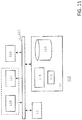
- FIG. 11 is a schematic block diagram of a general system, such as the system 1 for processing foot acceleration signals or a signal processing system 3.
- the data processing system 110 may include at least one processor 111 coupled to memory elements 112 through a system bus 113.
- the data processing system may store program code within memory elements 112.
- the processor 111 may execute the program code accessed from the memory elements 112 via a system bus 113.
- the data processing system may be implemented as a computer that is suitable for storing and/or executing program code. It should be appreciated, however, that the data processing system 110 may be implemented in the form of any system including a processor and a memory that is capable of performing the functions described within this specification.
- the memory elements 112 may include one or more physical memory devices such as, for example, local memory 114 and one or more bulk storage devices 115.
- the local memory may refer to random access memory or other non-persistent memory device(s) generally used during actual execution of the program code.
- a bulk storage device may be implemented as a hard drive or other persistent data storage device.
- the processing system 110 may also include one or more cache memories (not shown) that provide temporary storage of at least some program code in order to reduce the number of times program code must be retrieved from the bulk storage device 115 during execution.
- I/O devices depicted as an input device 116 and an output device 117 optionally can be coupled to the data processing system.
- input devices may include, but are not limited to, a keyboard, a pointing device such as a mouse, or the like.
- output devices may include, but are not limited to, a monitor or a display, speakers, or the like.
- Input and/or output devices may be coupled to the data processing system either directly or through intervening I/O controllers.
- the input and the output devices may be implemented as a combined input/output device (illustrated in FIG. 11 with a dashed line surrounding the input device 116 and the output device 117).
- a combined device is a touch sensitive display, also sometimes referred to as a "touch screen display” or simply "touch screen”.
- input to the device may be provided by a movement of a physical object, such as e.g. a stylus or a finger of a user, on or near the touch screen display.
- a network adapter 118 may also be coupled to the data processing system to enable it to become coupled to other systems, computer systems, remote network devices, and/or remote storage devices through intervening private or public networks.
- the network adapter may comprise a data receiver for receiving data that is transmitted by said systems, devices and/or networks to the data processing system 110, and a data transmitter for transmitting data from the data processing system 110 to said systems, devices and/or networks.
- Modems, cable modems, and Ethernet cards are examples of different types of network adapter that may be used with the data processing system 110.
- the memory elements 112 may store an application 119.
- the application 119 may be stored in the local memory 114, the one or more bulk storage devices 115, or apart from the local memory and the bulk storage devices.
- the data processing system 110 may further execute an operating system (not shown in FIG. 11 ) that can facilitate execution of the application 119.
- the application 119 being implemented in the form of executable program code, can be executed by the data processing system 110, e.g., by the processor 111. Responsive to executing the application, the data processing system 110 may be configured to perform one or more operations or method steps described herein.
- Various embodiments of the invention may be implemented as a program product for use with a computer system, where the program(s) of the program product define functions of the embodiments (including the methods described herein).
- the program(s) can be contained on a variety of non-transitory computer-readable storage media, where, as used herein, the expression "non-transitory computer readable storage media" comprises all computer-readable media, with the sole exception being a transitory, propagating signal.
- the program(s) can be contained on a variety of transitory computer-readable storage media.
- Illustrative computer-readable storage media include, but are not limited to: (i) non-writable storage media (e.g., read-only memory devices within a computer such as CD-ROM disks readable by a CD-ROM drive, ROM chips or any type of solid-state non-volatile semiconductor memory) on which information is permanently stored; and (ii) writable storage media (e.g., flash memory, floppy disks within a diskette drive or hard-disk drive or any type of solid-state random-access semiconductor memory) on which alterable information is stored.
- the computer program may be run on the processor 111 described herein.
Claims (12)
- System, das dafür konfiguriert ist, ein erstes Beschleunigungssignal zu verarbeiten, wobei das System aufweist:mindestens einen Beschleunigungssensor zum Messen der Beschleunigung eines Fußes während einer Bewegung des Fußes von einer ersten Position des Fußes auf einer Oberfläche zu einer zweiten Position des Fußes auf der Oberfläche und zum Erzeugen des ersten Beschleunigungssignals, das mehrere Beschleunigungswerte aufweist, als Antwort auf das Messen der Beschleunigung;ein Signalverarbeitungssystem, das dafür konfiguriert ist, einen oder mehrere Beschleunigungswerte in einem Peakbereich des ersten Beschleunigungssignals zu identifizieren, der einem Aufprall des Fußes auf die Oberfläche zugeordnet ist;dadurch gekennzeichnet, dassdas Signalverarbeitungssystem dafür konfiguriert ist, nach dem Identifizieren des einen oder der mehreren Beschleunigungswerte den identifizierten einen oder die identifizierten mehreren Beschleunigungswerte durch Berechnen eines oder mehrerer Beschleunigungswerte im Peakbereich des ersten Beschleunigungssignals zu verarbeiten, um ein zweites Beschleunigungssignal zu erhalten, das im Peakbereich, der dem Aufprall des Fußes auf die Oberfläche zugeordnet ist, glatt ist.
- System nach Anspruch 1, wobei das Verarbeiten aufweist:doppelte Integration des zweiten Beschleunigungssignals, das zwischen Zeiten gemessen wird, die der ersten Position des Fußes und der zweiten Position des Fußes zugeordnet sind;Bestimmen einer Schrittweite zwischen der ersten und der zweiten Position des Fußes als das Verarbeitungsergebnis aus der doppelten Integration des zweiten Beschleunigungssignals.
- System nach Anspruch 2, wobei das Bestimmen der Schrittweite aufweist:einfache Integration des zweiten Beschleunigungssignals, das zwischen Zeiten gemessen wird, die der ersten Position des Fußes und der zweiten Position des Fußes zugeordnet sind;Bestimmen einer Geschwindigkeit des Fußes zwischen der ersten Position des Fußes und der zweiten Position des Fußes aus dem zweiten Beschleunigungssignal;Anwenden einer Randbedingung, dass die Geschwindigkeit des Fußes entweder in der ersten Position oder in der zweiten Position des Fußes Null beträgt;Bestimmen eines Beschleunigungsfehlers durch Abgleichen des Beschleunigungsfehlers mit der Geschwindigkeit des Fußes entweder in der ersten oder in der zweiten Position des Fußes, geteilt durch eine Zeitdauer der Bewegung des Fußes von der ersten Position des Fußes zur zweiten Position des Fußes;Bestimmen eines Schrittweitenfehlers durch doppelte Integration des Beschleunigungsfehlers zwischen Zeiten, die der ersten Position des Fußes zur zweiten Position des Fußes zugeordnet sind; undKompensieren des Schrittweitenfehlers.
- System nach einem oder mehreren der Ansprüche 1 bis 3, wobei der identifizierte Beschleunigungswert oder die identifizierten Beschleunigungswerte im Peakbereich des ersten Beschleunigungssignals, der dem Aufprall des Fußes auf die Oberfläche zugeordnet ist, durch Anwenden einer Bedingung auf benachbarte Beschleunigungswerte im Peakbereich des ersten Beschleunigungssignals identifiziert werden.
- System nach einem oder mehreren der vorangehenden Ansprüche, wobei das Signalverarbeitungssystem dafür konfiguriert ist, aus dem identifizierten einen oder den identifizierten mehreren Beschleunigungswerten im Peakbereich des ersten Beschleunigungssignals Benutzerinformation als das Verarbeitungsergebnis zu bestimmen.
- System nach Anspruch 5, wobei die Benutzerinformation Trainingsinformation für den Benutzer und/oder Materialeigenschaften von am Fuß getragenem Schuhwerk aufweist.
- System nach einem oder mehreren der vorangehenden Ansprüche, wobei die erste Position des Fußes durch Anwenden einer Bedingung auf weitere Beschleunigungswerte identifiziert wird, die als Antwort auf das Messen einer Beschleunigung des Fußes in einer Richtung erhalten werden, die sich im Wesentlichen senkrecht zu der Oberfläche erstreckt.
- System nach einem oder mehreren der vorangehenden Ansprüche, wobei das System aufweist:eine erste Komponente, die den Beschleunigungssensor aufweist und am Fuß befestigbar ist; undeine zweite Komponente, die mindestens einen Teil des Signalverarbeitungssystems aufweist,wobei die erste und zweite Komponente separate Komponenten sind, undwobei die erste und die zweite Komponente dafür konfiguriert sind, sich miteinander zu verbinden, so dass zumindest das Verarbeitungsergebnis in der zweiten Komponente erhalten wird.
- Am Fuß tragbare Struktur mit dem System nach einem der vorangehenden Ansprüche.
- Computerimplementiertes Verfahren zum Verarbeiten eines ersten Beschleunigungssignals, wobei das Verfahren die Schritte aufweist:Messen einer Beschleunigung eines Fußes während einer Bewegung des Fußes von einer ersten Position des Fußes auf einer Oberfläche zu einer zweiten Position des Fußes auf der Oberfläche und Erzeugen des ersten Beschleunigungssignals, das mehrere Beschleunigungswerte aufweist, als Antwort auf das Messen der Beschleunigung durch mindestens einen Beschleunigungssensor;Verarbeiten des ersten Beschleunigungssignals durch ein Signalverarbeitungssystem, wobei die Verarbeitung aufweist:Identifizieren eines oder mehrerer Beschleunigungswerte in einem Peakbereich des ersten Beschleunigungssignals, der einem Aufprall des Fußes auf die Oberfläche zugeordnet ist; und dann Ausführen des KennzeichnungsschrittsVerarbeiten des identifizierten einen oder der mehreren Beschleunigungswerte durch Berechnen eines oder mehrerer Beschleunigungswerte im Peakbereich des ersten Beschleunigungssignals, um ein zweites Beschleunigungssignal zu erhalten, das in dem dem Aufprall des Fußes auf der Oberfläche zugeordneten Peakbereich glatt ist.
- Verfahren nach Anspruch 10, ferner mit Schritten in dem Signalverarbeitungssystem nach einem der Ansprüche 2 bis 8.
- Computerprogramm oder Folge von Computerprogrammen, das/die mindestens einen Softwarecodeabschnitt aufweist/aufweisen, oder ein Computerprogrammprodukt, das mindestens einen Softwarecodeabschnitt speichert, wobei der Softwarecodeabschnitt, wenn er auf einem Computersystem ausgeführt wird, dafür konfiguriert ist, das erste Beschleunigungssignals wie in Anspruch 10 oder 11 definiert ist zu verarbeiten.
Priority Applications (3)
| Application Number | Priority Date | Filing Date | Title |
|---|---|---|---|
| EP15175007.2A EP3112811B1 (de) | 2015-07-02 | 2015-07-02 | System und verfahren zur verarbeitung eines fussbeschleunigungssignals |
| US15/741,381 US20180188069A1 (en) | 2015-07-02 | 2016-07-01 | System and method for processing a foot acceleration signal |
| PCT/EP2016/065606 WO2017001688A1 (en) | 2015-07-02 | 2016-07-01 | System and method for processing a foot acceleration signal |
Applications Claiming Priority (1)
| Application Number | Priority Date | Filing Date | Title |
|---|---|---|---|
| EP15175007.2A EP3112811B1 (de) | 2015-07-02 | 2015-07-02 | System und verfahren zur verarbeitung eines fussbeschleunigungssignals |
Publications (2)
| Publication Number | Publication Date |
|---|---|
| EP3112811A1 EP3112811A1 (de) | 2017-01-04 |
| EP3112811B1 true EP3112811B1 (de) | 2019-02-27 |
Family
ID=53539515
Family Applications (1)
| Application Number | Title | Priority Date | Filing Date |
|---|---|---|---|
| EP15175007.2A Active EP3112811B1 (de) | 2015-07-02 | 2015-07-02 | System und verfahren zur verarbeitung eines fussbeschleunigungssignals |
Country Status (3)
| Country | Link |
|---|---|
| US (1) | US20180188069A1 (de) |
| EP (1) | EP3112811B1 (de) |
| WO (1) | WO2017001688A1 (de) |
Families Citing this family (2)
| Publication number | Priority date | Publication date | Assignee | Title |
|---|---|---|---|---|
| WO2019036926A1 (zh) * | 2017-08-23 | 2019-02-28 | 华为技术有限公司 | 基于加速信息的足部计步方法、装置及设备 |
| CN108937852B (zh) * | 2018-05-28 | 2021-06-22 | 深圳市北高智电子有限公司 | 一种智能计步运算方法 |
Family Cites Families (6)
| Publication number | Priority date | Publication date | Assignee | Title |
|---|---|---|---|---|
| US6018705A (en) * | 1997-10-02 | 2000-01-25 | Personal Electronic Devices, Inc. | Measuring foot contact time and foot loft time of a person in locomotion |
| EP0977974B1 (de) * | 1998-02-25 | 2004-10-13 | Koninklijke Philips Electronics N.V. | Verfahren und system zur leistungsmessung während einer übungsaktivität |
| US6826477B2 (en) * | 2001-04-23 | 2004-11-30 | Ecole Polytechnique Federale De Lausanne (Epfl) | Pedestrian navigation method and apparatus operative in a dead reckoning mode |
| US7827000B2 (en) * | 2006-03-03 | 2010-11-02 | Garmin Switzerland Gmbh | Method and apparatus for estimating a motion parameter |
| JP2014046087A (ja) * | 2012-09-03 | 2014-03-17 | Seiko Instruments Inc | 電子機器およびプログラム |
| US20150359291A1 (en) * | 2014-06-16 | 2015-12-17 | Shen-Ko Tseng | Automatic pedometer and automatic step-counting shoe |
-
2015
- 2015-07-02 EP EP15175007.2A patent/EP3112811B1/de active Active
-
2016
- 2016-07-01 WO PCT/EP2016/065606 patent/WO2017001688A1/en active Application Filing
- 2016-07-01 US US15/741,381 patent/US20180188069A1/en not_active Abandoned
Non-Patent Citations (1)
| Title |
|---|
| None * |
Also Published As
| Publication number | Publication date |
|---|---|
| EP3112811A1 (de) | 2017-01-04 |
| US20180188069A1 (en) | 2018-07-05 |
| WO2017001688A1 (en) | 2017-01-05 |
Similar Documents
| Publication | Publication Date | Title |
|---|---|---|
| JP6069590B2 (ja) | 歩数カウント方法及び装置 | |
| JP6567658B2 (ja) | ユーザーの活動を分類し及び/又はユーザーの歩数をカウントするデバイス及び方法 | |
| JP6183906B2 (ja) | 歩容推定装置とそのプログラム、転倒危険度算出装置とそのプログラム | |
| CN105210067B (zh) | 计算用户的与体育锻炼有关的生理状态 | |
| JP7327516B2 (ja) | 異常検出装置、判定システム、異常検出方法、およびプログラム | |
| JP6024134B2 (ja) | 状態検出装置、電子機器、測定システム及びプログラム | |
| CN108836344A (zh) | 步长步频估算方法和装置及步态检测仪 | |
| US10969241B2 (en) | Accelerometer-based systems and methods for quantifying steps | |
| EP3112811B1 (de) | System und verfahren zur verarbeitung eines fussbeschleunigungssignals | |
| JP6044670B2 (ja) | 歩行分析装置 | |
| WO2012036135A1 (ja) | 情報処理方法、情報処理装置、出力装置、情報処理システム、情報処理用プログラムおよび同プログラムを記録したコンピュータ読み取り可能な記録媒体 | |
| JP6564711B2 (ja) | 歩容推定装置、方法およびプログラム | |
| US11229399B2 (en) | System and method for monitoring efficiency versus fatigue | |
| EP3847961B1 (de) | Programm zur bestimmung des gehzustands, verfahren zur bestimmung des gehzustands und vorrichtung zur informationsverarbeitung | |
| KR101713496B1 (ko) | 가속도 센서를 이용한 무지연 실시간 걸음검출 시스템 및 방법 | |
| JP5952907B2 (ja) | 歩行様式判別システム、歩行様式判別装置及び歩行様式判別方法 | |
| KR102029576B1 (ko) | 생체 정보 추정 슈즈 및 이를 포함하는 시스템 | |
| WO2019229903A1 (ja) | 歩行計測システム、歩行計測プログラム、及び歩行計測方法 | |
| CN105095959B (zh) | 用于估测物体周期运动的方法及装置 | |
| JP6867448B2 (ja) | ユーザーの活動を分類し及び/又はユーザーの歩数をカウントするデバイス及び方法 | |
| KR102265479B1 (ko) | 보행 정보를 분석하기 위한 방법, 시스템 및 컴퓨터 판독 가능한 기록 매체 | |
| CN114279441B (zh) | 一种零速区间检测方法、行人导航系统及存储介质 | |
| US11035692B2 (en) | Technologies for pedometric sensing in footwear | |
| CN115188468A (zh) | 一种基于支持向量机的冻结步态检测方法、装置、和存储介质 | |
| CN117337205A (zh) | 跑法分析装置、跑法分析方法及跑法分析程序 |
Legal Events
| Date | Code | Title | Description |
|---|---|---|---|
| PUAI | Public reference made under article 153(3) epc to a published international application that has entered the european phase |
Free format text: ORIGINAL CODE: 0009012 |
|
| STAA | Information on the status of an ep patent application or granted ep patent |
Free format text: STATUS: REQUEST FOR EXAMINATION WAS MADE |
|
| 17P | Request for examination filed |
Effective date: 20160215 |
|
| AK | Designated contracting states |
Kind code of ref document: A1 Designated state(s): AL AT BE BG CH CY CZ DE DK EE ES FI FR GB GR HR HU IE IS IT LI LT LU LV MC MK MT NL NO PL PT RO RS SE SI SK SM TR |
|
| AX | Request for extension of the european patent |
Extension state: BA ME |
|
| D17P | Request for examination filed (deleted) | ||
| RBV | Designated contracting states (corrected) |
Designated state(s): AL AT BE BG CH CY CZ DE DK EE ES FI FR GB GR HR HU IE IS IT LI LT LU LV MC MK MT NL NO PL PT RO RS SE SI SK SM TR |
|
| R17P | Request for examination filed (corrected) |
Effective date: 20170626 |
|
| STAA | Information on the status of an ep patent application or granted ep patent |
Free format text: STATUS: EXAMINATION IS IN PROGRESS |
|
| 17Q | First examination report despatched |
Effective date: 20170914 |
|
| GRAP | Despatch of communication of intention to grant a patent |
Free format text: ORIGINAL CODE: EPIDOSNIGR1 |
|
| STAA | Information on the status of an ep patent application or granted ep patent |
Free format text: STATUS: GRANT OF PATENT IS INTENDED |
|
| INTG | Intention to grant announced |
Effective date: 20181025 |
|
| GRAS | Grant fee paid |
Free format text: ORIGINAL CODE: EPIDOSNIGR3 |
|
| GRAA | (expected) grant |
Free format text: ORIGINAL CODE: 0009210 |
|
| STAA | Information on the status of an ep patent application or granted ep patent |
Free format text: STATUS: THE PATENT HAS BEEN GRANTED |
|
| AK | Designated contracting states |
Kind code of ref document: B1 Designated state(s): AL AT BE BG CH CY CZ DE DK EE ES FI FR GB GR HR HU IE IS IT LI LT LU LV MC MK MT NL NO PL PT RO RS SE SI SK SM TR |
|
| REG | Reference to a national code |
Ref country code: GB Ref legal event code: FG4D |
|
| REG | Reference to a national code |
Ref country code: CH Ref legal event code: EP |
|
| REG | Reference to a national code |
Ref country code: AT Ref legal event code: REF Ref document number: 1102030 Country of ref document: AT Kind code of ref document: T Effective date: 20190315 |
|
| REG | Reference to a national code |
Ref country code: IE Ref legal event code: FG4D |
|
| REG | Reference to a national code |
Ref country code: DE Ref legal event code: R096 Ref document number: 602015025227 Country of ref document: DE |
|
| REG | Reference to a national code |
Ref country code: NL Ref legal event code: FP |
|
| REG | Reference to a national code |
Ref country code: LT Ref legal event code: MG4D |
|
| PG25 | Lapsed in a contracting state [announced via postgrant information from national office to epo] |
Ref country code: PT Free format text: LAPSE BECAUSE OF FAILURE TO SUBMIT A TRANSLATION OF THE DESCRIPTION OR TO PAY THE FEE WITHIN THE PRESCRIBED TIME-LIMIT Effective date: 20190627 Ref country code: LT Free format text: LAPSE BECAUSE OF FAILURE TO SUBMIT A TRANSLATION OF THE DESCRIPTION OR TO PAY THE FEE WITHIN THE PRESCRIBED TIME-LIMIT Effective date: 20190227 Ref country code: NO Free format text: LAPSE BECAUSE OF FAILURE TO SUBMIT A TRANSLATION OF THE DESCRIPTION OR TO PAY THE FEE WITHIN THE PRESCRIBED TIME-LIMIT Effective date: 20190527 Ref country code: FI Free format text: LAPSE BECAUSE OF FAILURE TO SUBMIT A TRANSLATION OF THE DESCRIPTION OR TO PAY THE FEE WITHIN THE PRESCRIBED TIME-LIMIT Effective date: 20190227 Ref country code: SE Free format text: LAPSE BECAUSE OF FAILURE TO SUBMIT A TRANSLATION OF THE DESCRIPTION OR TO PAY THE FEE WITHIN THE PRESCRIBED TIME-LIMIT Effective date: 20190227 |
|
| PG25 | Lapsed in a contracting state [announced via postgrant information from national office to epo] |
Ref country code: GR Free format text: LAPSE BECAUSE OF FAILURE TO SUBMIT A TRANSLATION OF THE DESCRIPTION OR TO PAY THE FEE WITHIN THE PRESCRIBED TIME-LIMIT Effective date: 20190528 Ref country code: IS Free format text: LAPSE BECAUSE OF FAILURE TO SUBMIT A TRANSLATION OF THE DESCRIPTION OR TO PAY THE FEE WITHIN THE PRESCRIBED TIME-LIMIT Effective date: 20190627 Ref country code: LV Free format text: LAPSE BECAUSE OF FAILURE TO SUBMIT A TRANSLATION OF THE DESCRIPTION OR TO PAY THE FEE WITHIN THE PRESCRIBED TIME-LIMIT Effective date: 20190227 Ref country code: HR Free format text: LAPSE BECAUSE OF FAILURE TO SUBMIT A TRANSLATION OF THE DESCRIPTION OR TO PAY THE FEE WITHIN THE PRESCRIBED TIME-LIMIT Effective date: 20190227 Ref country code: RS Free format text: LAPSE BECAUSE OF FAILURE TO SUBMIT A TRANSLATION OF THE DESCRIPTION OR TO PAY THE FEE WITHIN THE PRESCRIBED TIME-LIMIT Effective date: 20190227 Ref country code: BG Free format text: LAPSE BECAUSE OF FAILURE TO SUBMIT A TRANSLATION OF THE DESCRIPTION OR TO PAY THE FEE WITHIN THE PRESCRIBED TIME-LIMIT Effective date: 20190527 |
|
| REG | Reference to a national code |
Ref country code: AT Ref legal event code: MK05 Ref document number: 1102030 Country of ref document: AT Kind code of ref document: T Effective date: 20190227 |
|
| PG25 | Lapsed in a contracting state [announced via postgrant information from national office to epo] |
Ref country code: SK Free format text: LAPSE BECAUSE OF FAILURE TO SUBMIT A TRANSLATION OF THE DESCRIPTION OR TO PAY THE FEE WITHIN THE PRESCRIBED TIME-LIMIT Effective date: 20190227 Ref country code: EE Free format text: LAPSE BECAUSE OF FAILURE TO SUBMIT A TRANSLATION OF THE DESCRIPTION OR TO PAY THE FEE WITHIN THE PRESCRIBED TIME-LIMIT Effective date: 20190227 Ref country code: IT Free format text: LAPSE BECAUSE OF FAILURE TO SUBMIT A TRANSLATION OF THE DESCRIPTION OR TO PAY THE FEE WITHIN THE PRESCRIBED TIME-LIMIT Effective date: 20190227 Ref country code: CZ Free format text: LAPSE BECAUSE OF FAILURE TO SUBMIT A TRANSLATION OF THE DESCRIPTION OR TO PAY THE FEE WITHIN THE PRESCRIBED TIME-LIMIT Effective date: 20190227 Ref country code: RO Free format text: LAPSE BECAUSE OF FAILURE TO SUBMIT A TRANSLATION OF THE DESCRIPTION OR TO PAY THE FEE WITHIN THE PRESCRIBED TIME-LIMIT Effective date: 20190227 Ref country code: ES Free format text: LAPSE BECAUSE OF FAILURE TO SUBMIT A TRANSLATION OF THE DESCRIPTION OR TO PAY THE FEE WITHIN THE PRESCRIBED TIME-LIMIT Effective date: 20190227 Ref country code: DK Free format text: LAPSE BECAUSE OF FAILURE TO SUBMIT A TRANSLATION OF THE DESCRIPTION OR TO PAY THE FEE WITHIN THE PRESCRIBED TIME-LIMIT Effective date: 20190227 Ref country code: AL Free format text: LAPSE BECAUSE OF FAILURE TO SUBMIT A TRANSLATION OF THE DESCRIPTION OR TO PAY THE FEE WITHIN THE PRESCRIBED TIME-LIMIT Effective date: 20190227 |
|
| REG | Reference to a national code |
Ref country code: DE Ref legal event code: R097 Ref document number: 602015025227 Country of ref document: DE |
|
| PG25 | Lapsed in a contracting state [announced via postgrant information from national office to epo] |
Ref country code: PL Free format text: LAPSE BECAUSE OF FAILURE TO SUBMIT A TRANSLATION OF THE DESCRIPTION OR TO PAY THE FEE WITHIN THE PRESCRIBED TIME-LIMIT Effective date: 20190227 Ref country code: SM Free format text: LAPSE BECAUSE OF FAILURE TO SUBMIT A TRANSLATION OF THE DESCRIPTION OR TO PAY THE FEE WITHIN THE PRESCRIBED TIME-LIMIT Effective date: 20190227 |
|
| PG25 | Lapsed in a contracting state [announced via postgrant information from national office to epo] |
Ref country code: AT Free format text: LAPSE BECAUSE OF FAILURE TO SUBMIT A TRANSLATION OF THE DESCRIPTION OR TO PAY THE FEE WITHIN THE PRESCRIBED TIME-LIMIT Effective date: 20190227 |
|
| PLBE | No opposition filed within time limit |
Free format text: ORIGINAL CODE: 0009261 |
|
| STAA | Information on the status of an ep patent application or granted ep patent |
Free format text: STATUS: NO OPPOSITION FILED WITHIN TIME LIMIT |
|
| 26N | No opposition filed |
Effective date: 20191128 |
|
| PG25 | Lapsed in a contracting state [announced via postgrant information from national office to epo] |
Ref country code: SI Free format text: LAPSE BECAUSE OF FAILURE TO SUBMIT A TRANSLATION OF THE DESCRIPTION OR TO PAY THE FEE WITHIN THE PRESCRIBED TIME-LIMIT Effective date: 20190227 Ref country code: MC Free format text: LAPSE BECAUSE OF FAILURE TO SUBMIT A TRANSLATION OF THE DESCRIPTION OR TO PAY THE FEE WITHIN THE PRESCRIBED TIME-LIMIT Effective date: 20190227 |
|
| REG | Reference to a national code |
Ref country code: CH Ref legal event code: PL |
|
| GBPC | Gb: european patent ceased through non-payment of renewal fee |
Effective date: 20190702 |
|
| PG25 | Lapsed in a contracting state [announced via postgrant information from national office to epo] |
Ref country code: TR Free format text: LAPSE BECAUSE OF FAILURE TO SUBMIT A TRANSLATION OF THE DESCRIPTION OR TO PAY THE FEE WITHIN THE PRESCRIBED TIME-LIMIT Effective date: 20190227 |
|
| REG | Reference to a national code |
Ref country code: BE Ref legal event code: MM Effective date: 20190731 |
|
| PG25 | Lapsed in a contracting state [announced via postgrant information from national office to epo] |
Ref country code: GB Free format text: LAPSE BECAUSE OF NON-PAYMENT OF DUE FEES Effective date: 20190702 |
|
| PG25 | Lapsed in a contracting state [announced via postgrant information from national office to epo] |
Ref country code: LI Free format text: LAPSE BECAUSE OF NON-PAYMENT OF DUE FEES Effective date: 20190731 Ref country code: BE Free format text: LAPSE BECAUSE OF NON-PAYMENT OF DUE FEES Effective date: 20190731 Ref country code: LU Free format text: LAPSE BECAUSE OF NON-PAYMENT OF DUE FEES Effective date: 20190702 Ref country code: CH Free format text: LAPSE BECAUSE OF NON-PAYMENT OF DUE FEES Effective date: 20190731 |
|
| PG25 | Lapsed in a contracting state [announced via postgrant information from national office to epo] |
Ref country code: FR Free format text: LAPSE BECAUSE OF NON-PAYMENT OF DUE FEES Effective date: 20190731 |
|
| PG25 | Lapsed in a contracting state [announced via postgrant information from national office to epo] |
Ref country code: IE Free format text: LAPSE BECAUSE OF NON-PAYMENT OF DUE FEES Effective date: 20190702 |
|
| PG25 | Lapsed in a contracting state [announced via postgrant information from national office to epo] |
Ref country code: CY Free format text: LAPSE BECAUSE OF FAILURE TO SUBMIT A TRANSLATION OF THE DESCRIPTION OR TO PAY THE FEE WITHIN THE PRESCRIBED TIME-LIMIT Effective date: 20190227 |
|
| PG25 | Lapsed in a contracting state [announced via postgrant information from national office to epo] |
Ref country code: HU Free format text: LAPSE BECAUSE OF FAILURE TO SUBMIT A TRANSLATION OF THE DESCRIPTION OR TO PAY THE FEE WITHIN THE PRESCRIBED TIME-LIMIT; INVALID AB INITIO Effective date: 20150702 Ref country code: MT Free format text: LAPSE BECAUSE OF FAILURE TO SUBMIT A TRANSLATION OF THE DESCRIPTION OR TO PAY THE FEE WITHIN THE PRESCRIBED TIME-LIMIT Effective date: 20190227 |
|
| PG25 | Lapsed in a contracting state [announced via postgrant information from national office to epo] |
Ref country code: MK Free format text: LAPSE BECAUSE OF FAILURE TO SUBMIT A TRANSLATION OF THE DESCRIPTION OR TO PAY THE FEE WITHIN THE PRESCRIBED TIME-LIMIT Effective date: 20190227 |
|
| PGFP | Annual fee paid to national office [announced via postgrant information from national office to epo] |
Ref country code: NL Payment date: 20230726 Year of fee payment: 9 |
|
| PGFP | Annual fee paid to national office [announced via postgrant information from national office to epo] |
Ref country code: DE Payment date: 20230727 Year of fee payment: 9 |