EP3112673B1 - Spar cap for a wind turbine rotor blade formed from pre-cured laminate plates of varying thicknesses - Google Patents
Spar cap for a wind turbine rotor blade formed from pre-cured laminate plates of varying thicknesses Download PDFInfo
- Publication number
- EP3112673B1 EP3112673B1 EP16177105.0A EP16177105A EP3112673B1 EP 3112673 B1 EP3112673 B1 EP 3112673B1 EP 16177105 A EP16177105 A EP 16177105A EP 3112673 B1 EP3112673 B1 EP 3112673B1
- Authority
- EP
- European Patent Office
- Prior art keywords
- plates
- plate
- spar cap
- cured
- thickness
- Prior art date
- Legal status (The legal status is an assumption and is not a legal conclusion. Google has not performed a legal analysis and makes no representation as to the accuracy of the status listed.)
- Active
Links
- 238000009826 distribution Methods 0.000 claims description 9
- 230000003247 decreasing effect Effects 0.000 claims description 4
- IYFATESGLOUGBX-YVNJGZBMSA-N Sorbitan monopalmitate Chemical compound CCCCCCCCCCCCCCCC(=O)OC[C@@H](O)[C@H]1OC[C@H](O)[C@H]1O IYFATESGLOUGBX-YVNJGZBMSA-N 0.000 description 13
- 239000002131 composite material Substances 0.000 description 13
- 230000007704 transition Effects 0.000 description 12
- 239000000463 material Substances 0.000 description 8
- 239000000835 fiber Substances 0.000 description 7
- 229920005989 resin Polymers 0.000 description 7
- 239000011347 resin Substances 0.000 description 7
- 238000004519 manufacturing process Methods 0.000 description 6
- 229920000049 Carbon (fiber) Polymers 0.000 description 3
- 239000004917 carbon fiber Substances 0.000 description 3
- 239000003365 glass fiber Substances 0.000 description 3
- 238000000034 method Methods 0.000 description 3
- 230000008569 process Effects 0.000 description 3
- 238000005452 bending Methods 0.000 description 2
- 230000007547 defect Effects 0.000 description 2
- 239000004744 fabric Substances 0.000 description 2
- 239000010410 layer Substances 0.000 description 2
- VNWKTOKETHGBQD-UHFFFAOYSA-N methane Chemical compound C VNWKTOKETHGBQD-UHFFFAOYSA-N 0.000 description 2
- 238000012986 modification Methods 0.000 description 2
- 230000004048 modification Effects 0.000 description 2
- -1 polybutylene terephthalate Polymers 0.000 description 2
- 229920001707 polybutylene terephthalate Polymers 0.000 description 2
- 229920000139 polyethylene terephthalate Polymers 0.000 description 2
- 239000005020 polyethylene terephthalate Substances 0.000 description 2
- 238000006116 polymerization reaction Methods 0.000 description 2
- 230000009467 reduction Effects 0.000 description 2
- 239000004593 Epoxy Substances 0.000 description 1
- 240000007182 Ochroma pyramidale Species 0.000 description 1
- 239000000853 adhesive Substances 0.000 description 1
- 230000001070 adhesive effect Effects 0.000 description 1
- 230000006835 compression Effects 0.000 description 1
- 238000007906 compression Methods 0.000 description 1
- 238000010276 construction Methods 0.000 description 1
- 238000010924 continuous production Methods 0.000 description 1
- 239000011162 core material Substances 0.000 description 1
- 230000008878 coupling Effects 0.000 description 1
- 238000010168 coupling process Methods 0.000 description 1
- 238000005859 coupling reaction Methods 0.000 description 1
- 238000005336 cracking Methods 0.000 description 1
- 238000005516 engineering process Methods 0.000 description 1
- 239000004795 extruded polystyrene foam Substances 0.000 description 1
- 239000002657 fibrous material Substances 0.000 description 1
- 239000006260 foam Substances 0.000 description 1
- 230000006872 improvement Effects 0.000 description 1
- 238000001802 infusion Methods 0.000 description 1
- 239000002648 laminated material Substances 0.000 description 1
- 239000003562 lightweight material Substances 0.000 description 1
- 229920000728 polyester Polymers 0.000 description 1
- 229920002635 polyurethane Polymers 0.000 description 1
- 239000004814 polyurethane Substances 0.000 description 1
- 238000003825 pressing Methods 0.000 description 1
- 239000002356 single layer Substances 0.000 description 1
- 229920001567 vinyl ester resin Polymers 0.000 description 1
- 239000002023 wood Substances 0.000 description 1
Images


Classifications
-
- F—MECHANICAL ENGINEERING; LIGHTING; HEATING; WEAPONS; BLASTING
- F03—MACHINES OR ENGINES FOR LIQUIDS; WIND, SPRING, OR WEIGHT MOTORS; PRODUCING MECHANICAL POWER OR A REACTIVE PROPULSIVE THRUST, NOT OTHERWISE PROVIDED FOR
- F03D—WIND MOTORS
- F03D1/00—Wind motors with rotation axis substantially parallel to the air flow entering the rotor
- F03D1/06—Rotors
- F03D1/065—Rotors characterised by their construction elements
- F03D1/0675—Rotors characterised by their construction elements of the blades
-
- B—PERFORMING OPERATIONS; TRANSPORTING
- B32—LAYERED PRODUCTS
- B32B—LAYERED PRODUCTS, i.e. PRODUCTS BUILT-UP OF STRATA OF FLAT OR NON-FLAT, e.g. CELLULAR OR HONEYCOMB, FORM
- B32B1/00—Layered products having a general shape other than plane
-
- B—PERFORMING OPERATIONS; TRANSPORTING
- B32—LAYERED PRODUCTS
- B32B—LAYERED PRODUCTS, i.e. PRODUCTS BUILT-UP OF STRATA OF FLAT OR NON-FLAT, e.g. CELLULAR OR HONEYCOMB, FORM
- B32B21/00—Layered products comprising a layer of wood, e.g. wood board, veneer, wood particle board
- B32B21/04—Layered products comprising a layer of wood, e.g. wood board, veneer, wood particle board comprising wood as the main or only constituent of a layer, which is next to another layer of the same or of a different material
- B32B21/047—Layered products comprising a layer of wood, e.g. wood board, veneer, wood particle board comprising wood as the main or only constituent of a layer, which is next to another layer of the same or of a different material of foam
-
- B—PERFORMING OPERATIONS; TRANSPORTING
- B32—LAYERED PRODUCTS
- B32B—LAYERED PRODUCTS, i.e. PRODUCTS BUILT-UP OF STRATA OF FLAT OR NON-FLAT, e.g. CELLULAR OR HONEYCOMB, FORM
- B32B21/00—Layered products comprising a layer of wood, e.g. wood board, veneer, wood particle board
- B32B21/10—Next to a fibrous or filamentary layer
-
- B—PERFORMING OPERATIONS; TRANSPORTING
- B32—LAYERED PRODUCTS
- B32B—LAYERED PRODUCTS, i.e. PRODUCTS BUILT-UP OF STRATA OF FLAT OR NON-FLAT, e.g. CELLULAR OR HONEYCOMB, FORM
- B32B21/00—Layered products comprising a layer of wood, e.g. wood board, veneer, wood particle board
- B32B21/14—Layered products comprising a layer of wood, e.g. wood board, veneer, wood particle board comprising wood board or veneer
-
- B—PERFORMING OPERATIONS; TRANSPORTING
- B32—LAYERED PRODUCTS
- B32B—LAYERED PRODUCTS, i.e. PRODUCTS BUILT-UP OF STRATA OF FLAT OR NON-FLAT, e.g. CELLULAR OR HONEYCOMB, FORM
- B32B5/00—Layered products characterised by the non- homogeneity or physical structure, i.e. comprising a fibrous, filamentary, particulate or foam layer; Layered products characterised by having a layer differing constitutionally or physically in different parts
- B32B5/02—Layered products characterised by the non- homogeneity or physical structure, i.e. comprising a fibrous, filamentary, particulate or foam layer; Layered products characterised by having a layer differing constitutionally or physically in different parts characterised by structural features of a fibrous or filamentary layer
-
- B—PERFORMING OPERATIONS; TRANSPORTING
- B32—LAYERED PRODUCTS
- B32B—LAYERED PRODUCTS, i.e. PRODUCTS BUILT-UP OF STRATA OF FLAT OR NON-FLAT, e.g. CELLULAR OR HONEYCOMB, FORM
- B32B5/00—Layered products characterised by the non- homogeneity or physical structure, i.e. comprising a fibrous, filamentary, particulate or foam layer; Layered products characterised by having a layer differing constitutionally or physically in different parts
- B32B5/18—Layered products characterised by the non- homogeneity or physical structure, i.e. comprising a fibrous, filamentary, particulate or foam layer; Layered products characterised by having a layer differing constitutionally or physically in different parts characterised by features of a layer of foamed material
-
- B—PERFORMING OPERATIONS; TRANSPORTING
- B32—LAYERED PRODUCTS
- B32B—LAYERED PRODUCTS, i.e. PRODUCTS BUILT-UP OF STRATA OF FLAT OR NON-FLAT, e.g. CELLULAR OR HONEYCOMB, FORM
- B32B5/00—Layered products characterised by the non- homogeneity or physical structure, i.e. comprising a fibrous, filamentary, particulate or foam layer; Layered products characterised by having a layer differing constitutionally or physically in different parts
- B32B5/22—Layered products characterised by the non- homogeneity or physical structure, i.e. comprising a fibrous, filamentary, particulate or foam layer; Layered products characterised by having a layer differing constitutionally or physically in different parts characterised by the presence of two or more layers which are next to each other and are fibrous, filamentary, formed of particles or foamed
- B32B5/24—Layered products characterised by the non- homogeneity or physical structure, i.e. comprising a fibrous, filamentary, particulate or foam layer; Layered products characterised by having a layer differing constitutionally or physically in different parts characterised by the presence of two or more layers which are next to each other and are fibrous, filamentary, formed of particles or foamed one layer being a fibrous or filamentary layer
- B32B5/245—Layered products characterised by the non- homogeneity or physical structure, i.e. comprising a fibrous, filamentary, particulate or foam layer; Layered products characterised by having a layer differing constitutionally or physically in different parts characterised by the presence of two or more layers which are next to each other and are fibrous, filamentary, formed of particles or foamed one layer being a fibrous or filamentary layer another layer next to it being a foam layer
-
- B—PERFORMING OPERATIONS; TRANSPORTING
- B32—LAYERED PRODUCTS
- B32B—LAYERED PRODUCTS, i.e. PRODUCTS BUILT-UP OF STRATA OF FLAT OR NON-FLAT, e.g. CELLULAR OR HONEYCOMB, FORM
- B32B5/00—Layered products characterised by the non- homogeneity or physical structure, i.e. comprising a fibrous, filamentary, particulate or foam layer; Layered products characterised by having a layer differing constitutionally or physically in different parts
- B32B5/22—Layered products characterised by the non- homogeneity or physical structure, i.e. comprising a fibrous, filamentary, particulate or foam layer; Layered products characterised by having a layer differing constitutionally or physically in different parts characterised by the presence of two or more layers which are next to each other and are fibrous, filamentary, formed of particles or foamed
- B32B5/24—Layered products characterised by the non- homogeneity or physical structure, i.e. comprising a fibrous, filamentary, particulate or foam layer; Layered products characterised by having a layer differing constitutionally or physically in different parts characterised by the presence of two or more layers which are next to each other and are fibrous, filamentary, formed of particles or foamed one layer being a fibrous or filamentary layer
- B32B5/26—Layered products characterised by the non- homogeneity or physical structure, i.e. comprising a fibrous, filamentary, particulate or foam layer; Layered products characterised by having a layer differing constitutionally or physically in different parts characterised by the presence of two or more layers which are next to each other and are fibrous, filamentary, formed of particles or foamed one layer being a fibrous or filamentary layer another layer next to it also being fibrous or filamentary
-
- B—PERFORMING OPERATIONS; TRANSPORTING
- B32—LAYERED PRODUCTS
- B32B—LAYERED PRODUCTS, i.e. PRODUCTS BUILT-UP OF STRATA OF FLAT OR NON-FLAT, e.g. CELLULAR OR HONEYCOMB, FORM
- B32B7/00—Layered products characterised by the relation between layers; Layered products characterised by the relative orientation of features between layers, or by the relative values of a measurable parameter between layers, i.e. products comprising layers having different physical, chemical or physicochemical properties; Layered products characterised by the interconnection of layers
- B32B7/04—Interconnection of layers
- B32B7/12—Interconnection of layers using interposed adhesives or interposed materials with bonding properties
-
- B—PERFORMING OPERATIONS; TRANSPORTING
- B32—LAYERED PRODUCTS
- B32B—LAYERED PRODUCTS, i.e. PRODUCTS BUILT-UP OF STRATA OF FLAT OR NON-FLAT, e.g. CELLULAR OR HONEYCOMB, FORM
- B32B2260/00—Layered product comprising an impregnated, embedded, or bonded layer wherein the layer comprises an impregnation, embedding, or binder material
- B32B2260/02—Composition of the impregnated, bonded or embedded layer
- B32B2260/021—Fibrous or filamentary layer
- B32B2260/023—Two or more layers
-
- B—PERFORMING OPERATIONS; TRANSPORTING
- B32—LAYERED PRODUCTS
- B32B—LAYERED PRODUCTS, i.e. PRODUCTS BUILT-UP OF STRATA OF FLAT OR NON-FLAT, e.g. CELLULAR OR HONEYCOMB, FORM
- B32B2260/00—Layered product comprising an impregnated, embedded, or bonded layer wherein the layer comprises an impregnation, embedding, or binder material
- B32B2260/04—Impregnation, embedding, or binder material
- B32B2260/046—Synthetic resin
-
- B—PERFORMING OPERATIONS; TRANSPORTING
- B32—LAYERED PRODUCTS
- B32B—LAYERED PRODUCTS, i.e. PRODUCTS BUILT-UP OF STRATA OF FLAT OR NON-FLAT, e.g. CELLULAR OR HONEYCOMB, FORM
- B32B2262/00—Composition or structural features of fibres which form a fibrous or filamentary layer or are present as additives
- B32B2262/10—Inorganic fibres
- B32B2262/101—Glass fibres
-
- B—PERFORMING OPERATIONS; TRANSPORTING
- B32—LAYERED PRODUCTS
- B32B—LAYERED PRODUCTS, i.e. PRODUCTS BUILT-UP OF STRATA OF FLAT OR NON-FLAT, e.g. CELLULAR OR HONEYCOMB, FORM
- B32B2262/00—Composition or structural features of fibres which form a fibrous or filamentary layer or are present as additives
- B32B2262/10—Inorganic fibres
- B32B2262/106—Carbon fibres, e.g. graphite fibres
-
- B—PERFORMING OPERATIONS; TRANSPORTING
- B32—LAYERED PRODUCTS
- B32B—LAYERED PRODUCTS, i.e. PRODUCTS BUILT-UP OF STRATA OF FLAT OR NON-FLAT, e.g. CELLULAR OR HONEYCOMB, FORM
- B32B2266/00—Composition of foam
- B32B2266/02—Organic
- B32B2266/0214—Materials belonging to B32B27/00
- B32B2266/0221—Vinyl resin
- B32B2266/0228—Aromatic vinyl resin, e.g. styrenic (co)polymers
-
- B—PERFORMING OPERATIONS; TRANSPORTING
- B32—LAYERED PRODUCTS
- B32B—LAYERED PRODUCTS, i.e. PRODUCTS BUILT-UP OF STRATA OF FLAT OR NON-FLAT, e.g. CELLULAR OR HONEYCOMB, FORM
- B32B2307/00—Properties of the layers or laminate
- B32B2307/70—Other properties
- B32B2307/732—Dimensional properties
-
- B—PERFORMING OPERATIONS; TRANSPORTING
- B32—LAYERED PRODUCTS
- B32B—LAYERED PRODUCTS, i.e. PRODUCTS BUILT-UP OF STRATA OF FLAT OR NON-FLAT, e.g. CELLULAR OR HONEYCOMB, FORM
- B32B2603/00—Vanes, blades, propellers, rotors with blades
-
- F—MECHANICAL ENGINEERING; LIGHTING; HEATING; WEAPONS; BLASTING
- F05—INDEXING SCHEMES RELATING TO ENGINES OR PUMPS IN VARIOUS SUBCLASSES OF CLASSES F01-F04
- F05B—INDEXING SCHEME RELATING TO WIND, SPRING, WEIGHT, INERTIA OR LIKE MOTORS, TO MACHINES OR ENGINES FOR LIQUIDS COVERED BY SUBCLASSES F03B, F03D AND F03G
- F05B2230/00—Manufacture
- F05B2230/50—Building or constructing in particular ways
-
- F—MECHANICAL ENGINEERING; LIGHTING; HEATING; WEAPONS; BLASTING
- F05—INDEXING SCHEMES RELATING TO ENGINES OR PUMPS IN VARIOUS SUBCLASSES OF CLASSES F01-F04
- F05B—INDEXING SCHEME RELATING TO WIND, SPRING, WEIGHT, INERTIA OR LIKE MOTORS, TO MACHINES OR ENGINES FOR LIQUIDS COVERED BY SUBCLASSES F03B, F03D AND F03G
- F05B2240/00—Components
- F05B2240/20—Rotors
- F05B2240/30—Characteristics of rotor blades, i.e. of any element transforming dynamic fluid energy to or from rotational energy and being attached to a rotor
-
- F—MECHANICAL ENGINEERING; LIGHTING; HEATING; WEAPONS; BLASTING
- F05—INDEXING SCHEMES RELATING TO ENGINES OR PUMPS IN VARIOUS SUBCLASSES OF CLASSES F01-F04
- F05B—INDEXING SCHEME RELATING TO WIND, SPRING, WEIGHT, INERTIA OR LIKE MOTORS, TO MACHINES OR ENGINES FOR LIQUIDS COVERED BY SUBCLASSES F03B, F03D AND F03G
- F05B2250/00—Geometry
- F05B2250/30—Arrangement of components
- F05B2250/36—Arrangement of components in inner-outer relationship, e.g. shaft-bearing arrangements
-
- Y—GENERAL TAGGING OF NEW TECHNOLOGICAL DEVELOPMENTS; GENERAL TAGGING OF CROSS-SECTIONAL TECHNOLOGIES SPANNING OVER SEVERAL SECTIONS OF THE IPC; TECHNICAL SUBJECTS COVERED BY FORMER USPC CROSS-REFERENCE ART COLLECTIONS [XRACs] AND DIGESTS
- Y02—TECHNOLOGIES OR APPLICATIONS FOR MITIGATION OR ADAPTATION AGAINST CLIMATE CHANGE
- Y02E—REDUCTION OF GREENHOUSE GAS [GHG] EMISSIONS, RELATED TO ENERGY GENERATION, TRANSMISSION OR DISTRIBUTION
- Y02E10/00—Energy generation through renewable energy sources
- Y02E10/70—Wind energy
- Y02E10/72—Wind turbines with rotation axis in wind direction
-
- Y—GENERAL TAGGING OF NEW TECHNOLOGICAL DEVELOPMENTS; GENERAL TAGGING OF CROSS-SECTIONAL TECHNOLOGIES SPANNING OVER SEVERAL SECTIONS OF THE IPC; TECHNICAL SUBJECTS COVERED BY FORMER USPC CROSS-REFERENCE ART COLLECTIONS [XRACs] AND DIGESTS
- Y02—TECHNOLOGIES OR APPLICATIONS FOR MITIGATION OR ADAPTATION AGAINST CLIMATE CHANGE
- Y02P—CLIMATE CHANGE MITIGATION TECHNOLOGIES IN THE PRODUCTION OR PROCESSING OF GOODS
- Y02P70/00—Climate change mitigation technologies in the production process for final industrial or consumer products
- Y02P70/50—Manufacturing or production processes characterised by the final manufactured product
Definitions
- the present subject matter relates generally to wind turbines and, more particularly, to a spar cap for a wind turbine rotor blade formed from pre-cured laminate plates having varying thicknesses.
- Wind power is considered one of the cleanest, most environmentally friendly energy sources presently available, and wind turbines have gained increased attention in this regard.
- a modern wind turbine typically includes a tower, generator, gearbox, nacelle, and one or more rotor blades.
- the rotor blades capture kinetic energy from wind using known airfoil principles and transmit the kinetic energy through rotational energy to turn a shaft coupling the rotor blades to a gearbox, or if a gearbox is not used, directly to the generator.
- the generator then converts the mechanical energy to electrical energy that may be deployed to a utility grid.
- Wind turbine rotor blades typically include a body shell formed from a composite laminate material.
- the body shell is relatively lightweight and has structural properties (e.g., stiffness, buckling resistance and strength) which are not configured to withstand the bending moments and other loads exerted on the rotor blade during operation.
- structural properties e.g., stiffness, buckling resistance and strength
- wind turbine blades are becoming increasingly longer in order to produce more power. As a result, the blades must be stiffer and thus heavier so as to mitigate loads on the rotor.
- the body shell is typically reinforced using one or more structural components (e.g. opposed spar caps with a shear web configured therebetween) that engage the inner surfaces of the shell.
- the spar caps are typically constructed from laminate composites (e.g., glass fiber laminate composites and/or carbon fiber laminate composites) that include dry or non-cured fabric plies that are laid up within the blade mold and subsequently infused with resin.
- laminate composites e.g., glass fiber laminate composites and/or carbon fiber laminate composites
- Such materials can be difficult to control during the manufacturing process and/or are often defect prone and/or highly labor intensive due to handling of the non-cured fabrics and the challenges of infusing large laminated structures.
- Spar caps for a wind turbine blade are disclosed, for example, in US 2014/301859 A1 , US 2014/003956 A1 , and US 2013/149154 A1 .
- the outermost plate(s) of the spar cap may define a maximum plate thickness for the spar cap while the innermost plate(s) of the spar cap may define a minimum plate thickness for the spar cap.
- the arrangement of the pre-cured laminate plates may be reversed such that the outermost plate(s) of the spar cap define the minimum plate thickness while the innermost plate(s) of the spar cap define the maximum plate thickness.
- the thicknesses of the plates may be varied along the spanwise direction of the rotor blade.
- the spar cap may include thicker plates extending along the inboard region(s) of the rotor blade and thinner plates extending along the outboard region(s) of the blade.
- each specific plate arrangement may offer unique advantages when using such plates to form a spar cap for a wind turbine rotor blade.
- the use of pre-cured laminate plates having varying thicknesses may allow the overall spanwise thickness distribution for the spar cap to be specifically tailored to meet the particular design requirements for the rotor blade being manufactured.
- one or more embodiments of the present subject matter may allow for a reduction in the labor costs/time associated with manufacturing a spar cap and/or a reduction in the strain experienced within the individual plates forming the spar cap and/or may also allow for an improvement in the ability of the outermost spar cap plates to conform to the chordwise curvature of the rotor blade.
- the pre-cured laminate plates of the present subject matter may correspond to pultruded plates.
- "pultruded composites” or “pultrusions” generally encompass reinforced materials (e.g. fibers or woven or braided strands) that are impregnated with a resin and pulled through a heated stationary die such that the resin cures or undergoes polymerization.
- the process of manufacturing pultruded composites is typically characterized by a continuous process of composite materials that produces composite parts having a constant cross-section (e.g., a rectangular cross-section).
- the pre-cured laminate plates described herein may be formed using any other suitable process, such as a belt-pressing manufacturing process.
- FIG. 1 illustrates a side view of one embodiment of a wind turbine 10.
- the wind turbine 10 generally includes a tower 12 extending from a support surface 14 (e.g., the ground, a concrete pad or any other suitable support surface).
- the wind turbine 10 may also include a nacelle 16 mounted on the tower 12 and a rotor 18 coupled to the nacelle 16.
- the rotor 18 includes a rotatable hub 20 and at least one rotor blade 22 coupled to and extending outwardly from the hub 20.
- the rotor 18 includes three rotor blades 22.
- the rotor 18 may include more or less than three rotor blades 22.
- Each rotor blade 22 may be spaced about the hub 20 to facilitate rotating the rotor 18 to enable kinetic energy to be transferred from the wind into usable mechanical energy, and subsequently, electrical energy.
- the hub 20 may be rotatably coupled to an electric generator (not shown) positioned within the nacelle 16 to permit electrical energy to be produced.
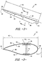
- FIGS. 2 and 3 one embodiment of a rotor blade 22 suitable for use within the wind turbine 10 shown in FIG. 1 is illustrated in accordance with aspects of the present subject matter.
- FIG. 2 illustrates a perspective view of the rotor blade 22.
- FIG. 3 illustrates a cross-sectional view of the rotor blade 22 taken about line 3-3 shown in FIG. 2 .
- the rotor blade 22 generally includes a blade root 24 configured to be mounted or otherwise secured to the hub 20 ( FIG. 1 ) of the wind turbine 10 and a blade tip 26 disposed opposite the blade root 24. Additionally, the rotor blade 22 may include a body shell 28 configured to extend between the blade root 24 and the blade tip 26 along a longitudinal or spanwise axis 30 of the blade 22.
- the body shell 28 may generally serve as the outer casing/covering of the rotor blade 22 and may define a substantially aerodynamic profile, such as by defining a symmetrical or cambered airfoil-shaped cross-section. As shown in FIG.
- the body shell 28 may also define a pressure side 32 and a suction side 34 extending between leading and trailing ends 36, 38 of the rotor blade 22.
- the rotor blade 22 may also have a span 40 defining the total length between the blade root 24 and the blade tip 26 and a chord 42 defining the total length between the leading edge 36 and the trailing edge 38.
- the chord 42 may generally vary in length with respect to the span 40 as the rotor blade 22 extends from the blade root 24 to the blade tip 26.
- the body shell 28 of the rotor blade 22 may be formed from a plurality of shell components or sections.
- the body shell 28 may be manufactured from a first shell half or section generally defining the pressure side 32 of the rotor blade 22 and a second shell half or section generally defining the suction side 34 of the rotor blade 22, with such shell sections being secured to one another at the leading and trailing ends 36, 38 of the blade 22.
- the body shell 28 may be formed from any other suitable number and/or arrangement of shell sections.
- the body shell 28 may be segmented along the spanwise axis 30 of the rotor blade 22, with each spanwise segment being formed from one or more shell sections.
- the body shell 28 may generally be formed from any suitable material.
- the body shell 28 may be formed entirely from a laminate composite material, such as a carbon fiber reinforced laminate composite or a glass fiber reinforced laminate composite.
- one or more portions of the body shell 28 may be configured as a layered construction and may include a core material, formed from a lightweight material such as wood (e.g., balsa), foam (e.g., extruded polystyrene foam) or a combination of such materials, disposed between layers of laminate composite material.
- the rotor blade 22 may also include one or more longitudinally extending structural components configured to provide increased stiffness, buckling resistance and/or strength to the blade 22.
- the rotor blade 22 may include a pair of longitudinally extending spar caps 44, 46 configured to be engaged against the opposing inner surfaces 48, 50 of the pressure and suction sides 32, 34 of the rotor blade 22, respectively.
- one or more shear webs 52 may be disposed between the spar caps 44, 46 so as to form a beam-like configuration.
- the spar caps 44, 46 may generally be designed to control the bending stresses and/or other loads acting on the rotor blade 22 in a generally spanwise direction (a direction parallel to the span 40 of the rotor blade 22) during operation of a wind turbine 10. Similarly, the spar caps 44, 46 may also be designed to withstand the spanwise compression occurring during operation of the wind turbine 10.
- FIG. 4 a close-up, cross-sectional view of one of the spar caps 46 shown in FIG. 3 is illustrated in accordance with aspects of the present subject matter, particularly illustrating the spar cap 46 being constructed or formed from a plurality of pre-cured laminate plates 100.
- FIG. 5 illustrates a more detailed, cross-sectional view of a portion of one of the pre-cured laminate plates 100 shown in FIG. 4 .
- each pre-cured plate 100 may correspond to a pultruded plate.
- one or more fiber materials 102 e.g., glass or carbon fibers
- the fibers 102 may be impregnated with at least one resin material 104 using any suitable means.
- the resin material 104 may include any suitable resin, including but not limited to polyester, polyurethane, polybutylene terephthalate (PBT), polyethylene terephthalate (PET), vinyl ester, epoxy, or similar.
- the impregnated fibers 102 may then be pulled through a heated stationary die such that the resin 104 cures or undergoes polymerization to form each plate 100.
- the individually formed plates 100 may then be assembled or joined together (e.g., via a secondary infusion process) to form the resulting spar cap 46.
- each of the pre-cured laminate plates 100 may form a single layer 106 of the spar cap 46.
- the layers 106 may then be stacked one on top of the other and joined together using any suitable means, for example, by vacuum infusing the plates 100 together or by bonding the plates 100 together via an adhesive, a semi-preg material, or a pre-preg material, to form the spar cap 46.
- the fibers 102 included within each plate 100 may generally be oriented in a common fiber direction 108.
- the fiber direction 108 may extend parallel to the longitudinal or spanwise direction of the rotor blade 22.
- the fibers 102 contained within each plate 104 used to form the spar cap 46 may generally extending spanwise along the length of the spar cap 46 between the blade root 24 and the blade tip 26.
- the assembly of pre-cured laminate plates 100 forming the spar cap 46 may include an outermost plate 100A positioned directly adjacent to the inner surface 50 of the body shell 28 of the rotor blade 22, an innermost plate 100G positioned opposite the outermost plate 100A (and, thus, disposed furthest away from the inner surface 50 of the body shell 28) and a plurality of intermediate plates (e.g., plates 100B-100F) positioned between the outermost and innermost plates 100A, 100G.
- the spar cap 46 is shown in FIG. 4 as being formed from seven pre-cured laminate plates 100. However, in general, the spar cap 46 may be formed from any number of pre-cured laminate plates 100, such as less than seven plates or more than seven plates.
- the plates 100 may be configured to define variable thicknesses 112. Specifically, as will be described below, at least one of the plates 100 may be configured to define a plate thickness in a flapwise or thickness direction of the rotor blade 22 (indicated by arrow 110 in FIGS. 3 and 4 ) that varies from the plate thickness(es) of the other plates 100 used to form the spar cap 46.
- the thicknesses of the plates 100 may be varied such that the plate(s) 100 positioned closest to the inner surface 50 of the body shell 28 (e.g., the outermost plate 100A and, optionally, one or more adjacent plates, such as plates 100B and 100C) define a plate thickness(es) 112A that differs significantly from the plate thickness(es) 112B defined by the plate(s) 100 positioned furthest away from the inner surface 50 of the body shell 28 (e.g., the innermost plate 100G and, optionally, one or more adjacent plates, such as plates 100E and 100F). 2.
- the plate thickness 112A of the plate(s) 100 positioned closest to the inner surface 50 may differ from the plate thickness 112B of the plate(s) 100 positioned furthest away from the inner surface 50 by at least50%, such as at least about 60% or at least about 70% or at least about 80% or at least about 90% and/or any other subranges therebetween.
- the plate(s) 100 positioned closest to the inner surface 50 are thicker than the plate(s) 100 positioned furthest away from the inner surface 50.
- the plate(s) 100 positioned closest to the inner surface 50 may be thinner than the plate(s) 100 positioned furthest away from the inner surface 50.
- FIG. 6 a schematic, spanwise view of one embodiment of the spar cap 46 shown in FIG. 4 is illustrated in accordance with aspects of the present subject matter.
- the various pre-cured laminate plates 100 forming the spar cap 46 may generally be stacked or assembled so as to decrease in spanwise length from the outermost plate 100A to the innermost plate 100G.
- the outermost plate 100A may generally define the longest spanwise length 114 (e.g., a length equal or substantially equal to the span 40 of the rotor blade 22 such that the plate 100A extends generally from the blade root 24 to the blade tip 26) and the innermost plate 100B may generally define the shortest spanwise length 116 (e.g., a length equal to about 0% to about 30% of the span 40 of the rotor blade 22).
- the spanwise ends of the plates 100 are, according to the invention, offset from one another such that spar cap 46 generally defines a tapered thickness distribution along the spanwise direction of the blade 22.
- an overall thickness 118 of the spar cap 46 may steadily increase from zero or substantially zero at the blade root 24 to a maximum spar cap thickness at a first spanwise location 120 defined along the spar cap 46 (e.g., at a distance from the root 24 equal to about 10% to about 25% of the span 40) and may then remain generally constant from the first spanwise location 120 to a second spanwise location 122 defined along the spar cap 46 (e.g., at a distance from the root 24 equal to about 25% to about 40% of the span 40), with the thickness 118 steadily decreasing from the maximum thickness to zero or substantially zero as the spar cap 46 extends outwardly from the second spanwise location 122 towards the blade tip 26.
- the spar cap 46 may be configured to define any other suitable thickness distribution or profile along its spanwise length.
- the thickness 118 of the spar cap 46 along its spanwise length may taper to a point at the outermost plate 100G such that the thickness distribution/profile of the spar cap 46 has a triangular or pyramidal shape.
- the thickness distribution/profile may define a curvilinear shape in the spanwise direction of the rotor blade 22.
- the pre-cured laminate plates 100 used to form the spar cap 46 define varying plate thicknesses.
- the plates 100 may be stacked or arranged so that the thickest plates are located closest to the inner surface 50 of the blade shell 28. For instance, as shown in FIG.
- the plates 100 used to form the spar cap 46 define three different plate thicknesses (e.g., thicknesses T 1 , T 2 , T 3 ), with the three outermost plates (e.g., 100A, 100B, 100C) defining the maximum plate thickness (T 1 ) of the spar cap 46, the three innermost plates (e.g., 100G, 100F, 100E) defining the minimum plate thickness (T 2 ) for the spar cap 46 and the central plate (e.g., 100D) defining an intermediate plate thickness (T 3 ) for the spar cap 46.
- the three outermost plates e.g., 100A, 100B, 100C
- T 1 maximum plate thickness
- the three innermost plates e.g., 100G, 100F, 100E
- T 2 minimum plate thickness
- the central plate e.g., 100D
- the thicknesses of the plates 100 used to form the spar cap 46 may be varied in any other suitable manner that provides for the plate(s) positioned closest to the inner surface 50 of the blade shell 28 to be thicker than the plate(s) positioned further away from the inner surface 50.
- the plates 100 used to form the spar cap 46 may only define two different thicknesses.
- the plates 100 may be assembled such that the thicker plates are positioned closest to the inner surface 50 of the blade shell 28 and the thinner plates are positioned further away from the inner surface 50.
- the spar cap 46 may be formed from plates 100 defining more than three different plate thicknesses.
- each plate 100 may be configured to define a plate thickness that differs from the plate thicknesses of the other plates 100 used to form the spar cap 46.
- An example of such an embodiment is illustrated in FIG. 7 .
- the outermost plate 100A may be configured to define a maximum plate thickness (e.g., thickness T A ) for the spar cap 46 and the innermost plate 100G may be configured to define a minimum plate thickness (e.g., thickness T G ) for the spar cap 46, with the plate thicknesses of the intermediate plates 100B-100F (e.g., thicknesses T B -T F ) steadily decreasing from the outermost plate 100A and the innermost plate 100G.
- the thicknesses of the plates 100 may continuously decrease as the spar cap 46 extends in the thickness direction 118 of the rotor blade 22 from the outermost plate 100A to the innermost plate 100G.
- the minimum plate thickness for the plates 100 used to form the spar cap 46 may be equal to less than 50% of the maximum plate thickness for the plates 100.
- the minimum plate thickness may be equal to less than about 40% of the maximum plate thickness, such as less than about 30% of the maximum plate thickness or less than about 20% of the maximum plate thickness or less than about 10% of the maximum plate thickness and/or any other subranges therebetween.
- the use of thicker plates as the outermost plates for the spar cap 46 may ensure that the plates terminate in low strain regions of the blade 22 (e.g., at or adjacent to the blade root 24 and the blade tip 26) as opposed to the higher strain regions of the blade 22 (e.g., along the portion of the span 40 across which the maximum spar cap thickness 118 is defined).
- the use of thinner plates 100 as the innermost plate(s) for the spar cap may allow for finer adjustments to be made to the overall spar cap thickness, thereby allowing the spanwise thickness distribution to be specifically tailored.
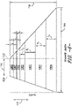
- FIG. 8 a schematic, spanwise view of another embodiment of a spar cap 46 formed from a plurality of pre-cured laminate plates 100 defining varying thicknesses is illustrated in accordance with aspects of the present subject matter.
- the plates 100 may be stacked or arranged so that the thinnest plates are located closest to the inner surface 50 of the blade shell 28. For instance, as shown in FIG.
- the plates 100 used to form the spar cap 46 define three different plate thicknesses (e.g., thicknesses T 1 , T 2 , T 3 ), with the three outermost plates (e.g., 100A, 100B, 100C) defining the minimum plate thickness (T 3 ) of the spar cap 46, the three innermost plates (e.g., 100G, 100F, 100E) defining the maximum plate thickness (T 2 ) for the spar cap 46 and the central plate (e.g., 100D) defining an intermediate plate thickness (T 3 ) for the spar cap 46.
- the three outermost plates e.g., 100A, 100B, 100C
- T 3 minimum plate thickness
- the three innermost plates e.g., 100G, 100F, 100E
- T 2 maximum plate thickness
- the central plate e.g., 100D
- the thicknesses of the plates 100 used to form the spar cap 46 may be varied in any other suitable manner that provides for the plate(s) positioned closest to the inner surface 50 of the blade shell 28 to be thinner than the plate(s) positioned further away from the inner surface 50.
- the plates 100 used to form the spar cap 46 may only define two different thicknesses.
- the plates 100 may be assembled such that the thinner plates are positioned closest to the inner surface 50 of the blade shell 28 and the thicker plates are positioned further away from the inner surface 50.
- the spar cap 46 may be formed from plates 100 defining more than three different plate thicknesses.
- each plate 100 may be configured to define a plate thickness that differs from the plate thicknesses of the other plates 100 used to form the spar cap 46.
- An example of such an embodiment is illustrated in FIG. 9 .
- the outermost plate 100A may be configured to define a minimum plate thickness (e.g., thickness T A ) for the spar cap 46 and the innermost plate 100G may be configured to define a maximum plate thickness (e.g., thickness T G ) for the spar cap 46, with the plate thicknesses of the intermediate plates 100B-100F (e.g., thicknesses T B -T F ) steadily increasing from the outermost plate 100A and the innermost plate 100G.
- the thicknesses of the plates 100 may continuously increase as the spar cap 46 extends in the thickness direction 118 of the rotor blade 22 from the outermost plate 100A to the innermost plate 100G.
- the thicker plates may then be added as short plies, which are typically located at inboard regions of the rotor blade 22 (e.g., less than 50% of the blade span 40 from the blade root 24) that define less chordwise curvature.
- thinner plates are able to be rolled up and/or otherwise handled more easily. As such, it may be desirable to use thinner plates to form the longer outermost plate(s) since longer, thinner plates can be transported more easily than longer, thicker plates.
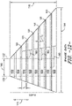
- FIG. 10 a schematic, spanwise view of a non-claimed embodiment of a spar cap 46 formed from a plurality of pre-cured laminate plates 100 defining varying thicknesses is illustrated in accordance with aspects of the present subject matter.
- the plates 100 may be stacked or arranged so that the thinner plates are located along the outer and inner portions of the spar cap 46, with the thicker plates being more centrally located within the spar cap 46 along its thickness direction 110. For instance, as shown in FIG.
- the two outermost plates (e.g., plates 100A and 100B) and the two innermost plates (e.g., plates 100G and 100F) correspond to the thinnest plates (e.g., by defining a minimum plate thickness T 1 of the spar cap 46), with the intermediate plates (e.g., plates 100C, 100D and 100E) positioned between the innermost and outermost plates corresponding to the thickest plates (e.g., by defining a maximum plate thickness T 2 of the spar cap 46).
- the thicknesses of the plates 100 used to form the spar cap 46 may be varied in any other suitable manner that provides for the plate(s) located along the outer and inner portions of the spar cap 46 to be thinner than the more centrally located plate(s).
- the outermost plate(s) e.g., plates 100A and 100B
- the innermost plate(s) e.g., plates 100G and 100F
- the centrally located plate(s) need not define a uniform thickness.
- the centrally located plates e.g., plates 100C, 100D and 100E
- the centrally located plates may define varying thicknesses, with the thicknesses of such plates still being thicker than the outermost and innermost plates.
- the use of one or more thinner plates as the outermost plate(s) for the spar cap 46 may allow for the plate(s) to more easily conform to the chordwise curvature of the rotor blade 22 while the use of one or more thinner plates as the innermost plate(s) for the spar cap 46 may allow for finer adjustments to be made to the overall spar cap thickness.
- the thickness of the spar cap 46 may be built-up quickly using fewer plates.
- FIG. 11 a schematic, spanwise view of a non-claimed embodiment of a spar cap 46 formed from a plurality of pre-cured laminate plates 100, 101 defining varying thicknesses is illustrated in accordance with aspects of the present subject matter. As shown, in contrast to the embodiments described above with reference to FIGS. 6-10 , the thickness of the plates 100, 101 is varied in the spanwise direction of the rotor blade 22 as opposed to the thickness direction 110.
- a plurality of thicker plates 100 may be stacked one on top of the other to form an inboard portion 150 of the spar cap 46 that extends outwardly from the blade root 24 and a plurality of thinner plates 101 may be stacked one on top of the other to form an outboard portion 152 of the spar cap 46 that extends outwardly from the inboard portion 150 of the spar cap 46 towards the blade tip 26.
- the thicker plates 100 may generally define a plate thickness (T 1 ) that is greater than the plate thickness (T 2 ) of the thinner plates 101.
- the thicker plates 100 are shown in FIG. 11 as defining a uniform plate thickness (T 1 ), the thicknesses of such plates 100 may also be varied along the thickness direction 110 of the spar cap 46, such as by varying the thicknesses of such plates 100 between the innermost and outermost plates.
- the thinner plates 101 are shown in FIG. 11 as defining a uniform plate thickness (T 2 ), the thicknesses of such plates 101 may also be varied along the thickness direction 110 of the spar cap 46, such as by varying the thickness of such plates 101between the innermost and outermost plates.
- the specific spanwise location(s) at which the spar cap transitions from the thicker plates 100 to the thinner plates 101 may generally vary depending on the desired spar cap characteristics and/or the configuration of the corresponding rotor blade 22.
- the transition location may be selected such that the thinner plates 101 extend along the outboard region(s) of the rotor blade 22 having the highest chordwise curvature, thereby allowing such plates 101 to be used to more easily conform to the blade curvature.
- the transition location may be selected such that the thinner plates 101 extend along the outboard region(s) of the rotor blade 22 having the highest chordwise curvature, thereby allowing such plates 101 to be used to more easily conform to the blade curvature.
- the spar cap 46 transitions from the thicker plates 100 to the thinner plates 101 at a spanwise transition location(s) (e.g., along a tapered transition line 154) ranging from about 40% to about 60% of the span 40 of the rotor blade 22.
- a spanwise transition location(s) e.g., along a tapered transition line 154
- the spanwise transition location(s) may be defined at a location(s) inboard of 40% of the blade span 40 or at location(s) outboard of 60% of the blade span 40.
- the transition between the thicker plates 100 and the thinner plates 101 may be tapered in the opposite direction or may occur at a single spanwise location (e.g., along a transition line extending parallel to the thickness direction 110).
- the plates 100, 101 may be configured to overlap one another in the spanwise direction as the spar cap 46 transitions form the thicker plates 100 to the thinner plates 101.
- FIG. 12 illustrates a non-claimed alternative embodiment of the spar cap 46 shown in FIG. 11 having overlapping or inter-leafed thicker and thinner plates 100, 101.
- adjacent thicker plates 100 and adjacent thinner plates 101 of the spar cap 46 have been shown as being spaced apart to clearly illustrate the overlap between the thicker and thinner plates 100, 101.
- the adjacent thicker plates 100 and the adjacent thinner plates 101 would be stacked one on top of the other during assembly so that the obvious gaps shown in FIG. 12 would not be present.
- the thicker plates 100 and the thinner plates 101 are inter-leafed with one another such that an overlapped region 160 is defined between each thinner plate 101 and the adjacent thicker plates 100.
- Such overlapping of the thicker plates 100 and the thinner plates 101 along the transition region of the spar cap 46 may allow for loads to be transferred between such plates 100, 101 via interlaminar shear, which may increase the load carrying capability of the spar cap 46.
- FIGS. 6-12 are simply provided as examples of suitable stacking arrangements using pre-cured laminate plates of differing thicknesses.
- any other suitable stacking arrangement may be utilized, including any suitable pattern of thick and thin plates.
- the plates may be alternated between thick and thin plates as the spar cap is assembled in the thickness direction.
Applications Claiming Priority (1)
| Application Number | Priority Date | Filing Date | Title |
|---|---|---|---|
| US14/754,764 US10072632B2 (en) | 2015-06-30 | 2015-06-30 | Spar cap for a wind turbine rotor blade formed from pre-cured laminate plates of varying thicknesses |
Publications (2)
| Publication Number | Publication Date |
|---|---|
| EP3112673A1 EP3112673A1 (en) | 2017-01-04 |
| EP3112673B1 true EP3112673B1 (en) | 2022-05-11 |
Family
ID=56296646
Family Applications (1)
| Application Number | Title | Priority Date | Filing Date |
|---|---|---|---|
| EP16177105.0A Active EP3112673B1 (en) | 2015-06-30 | 2016-06-30 | Spar cap for a wind turbine rotor blade formed from pre-cured laminate plates of varying thicknesses |
Country Status (5)
| Country | Link |
|---|---|
| US (1) | US10072632B2 (pt) |
| EP (1) | EP3112673B1 (pt) |
| CN (1) | CN106321345B (pt) |
| BR (1) | BR102016015249B1 (pt) |
| ES (1) | ES2913285T3 (pt) |
Families Citing this family (8)
| Publication number | Priority date | Publication date | Assignee | Title |
|---|---|---|---|---|
| US9845786B2 (en) * | 2014-12-12 | 2017-12-19 | General Electric Company | Spar cap for a wind turbine rotor blade |
| CN108626076A (zh) * | 2017-03-21 | 2018-10-09 | 中材科技风电叶片股份有限公司 | 叶根挡板与叶根的连接结构 |
| DE102017108902A1 (de) * | 2017-04-26 | 2018-10-31 | Wobben Properties Gmbh | Verfahren zur zeitgleichen Herstellung von zwei oder mehr Faserverbundbauteilen sowie Faserverbundbauteil |
| US10465653B2 (en) | 2017-06-21 | 2019-11-05 | General Electric Company | Wind turbine blade with hybrid spar cap and associated method for making |
| US11225942B2 (en) * | 2017-07-05 | 2022-01-18 | General Electric Company | Enhanced through-thickness resin infusion for a wind turbine composite laminate |
| US20210404443A1 (en) * | 2018-11-20 | 2021-12-30 | Vestas Wind Systems A/S | Equipotential bonding of wind turbine rotor blade |
| US11542844B2 (en) * | 2019-09-20 | 2023-01-03 | Raytheon Technologies Corporation | Integrated lubricating fluid filtering and metering device |
| CN113339188B (zh) * | 2021-06-29 | 2024-04-09 | 三一重能股份有限公司 | 一种风电叶片主梁结构及其制备方法和风电叶片 |
Family Cites Families (91)
| Publication number | Priority date | Publication date | Assignee | Title |
|---|---|---|---|---|
| JPH0674142A (ja) * | 1992-08-26 | 1994-03-15 | Mitsubishi Heavy Ind Ltd | 風車用frp翼の主桁及びその製造方法 |
| FR2760681B1 (fr) | 1997-03-12 | 1999-05-14 | Alternatives En | Procede de fabrication d'une piece de grandes dimensions en materiau composite et pale d'helice, en particulier d'eolienne, fabriquee selon ce procede |
| JP3930200B2 (ja) | 1998-10-06 | 2007-06-13 | 三菱重工業株式会社 | 風力発電翼の製造方法 |
| DK176335B1 (da) | 2001-11-13 | 2007-08-20 | Siemens Wind Power As | Fremgangsmåde til fremstilling af vindmöllevinger |
| DE10214340C1 (de) | 2002-03-28 | 2003-11-27 | Aerodyn Eng Gmbh | Blattanschluß für die Rotorblätter einer Windenergieanlage und Verfahren zu dessen Herstellung |
| EP1486415A1 (en) | 2003-06-12 | 2004-12-15 | SSP Technology A/S | Wind turbine blade and method of manufacturing a blade root |
| DE10336461A1 (de) | 2003-08-05 | 2005-03-03 | Aloys Wobben | Verfahren zur Herstellung eines Rotorblattes einer Windenergieanlage |
| DK1668246T3 (en) | 2003-09-29 | 2015-01-19 | Vestas Wind Sys As | WINDOW LOCK PROTECTION SYSTEM FOR A WIND MILL |
| WO2006002621A1 (en) | 2004-06-30 | 2006-01-12 | Vestas Wind Systems A/S | Wind turbine blades made of two separate sections, and method of assembly |
| WO2006070171A1 (en) | 2004-12-29 | 2006-07-06 | Vestas Wind Systems A/S | Method of manufacturing a wind turbine blade shell member with a fastening member and a wind turbine blade with a fastening member |
| DK176564B1 (da) | 2004-12-29 | 2008-09-01 | Lm Glasfiber As | Fiberforstærket samling |
| CN101137841B (zh) | 2005-02-03 | 2013-01-09 | 维斯塔斯风力系统有限公司 | 制造风轮机叶片壳体构件的方法 |
| DK2317125T3 (da) | 2005-02-22 | 2021-05-25 | Vestas Wind Sys As | Vindmølle og vinge dertil |
| ES2265760B1 (es) | 2005-03-31 | 2008-01-16 | GAMESA INNOVATION & TECHNOLOGY, S.L. | Pala para generadores eolicos. |
| US8142162B2 (en) | 2005-07-15 | 2012-03-27 | Vestas Wind Systems A/S | Wind turbine blade |
| JP2007092716A (ja) | 2005-09-30 | 2007-04-12 | Toray Ind Inc | 翼構造体およびその製造方法 |
| US7517198B2 (en) | 2006-03-20 | 2009-04-14 | Modular Wind Energy, Inc. | Lightweight composite truss wind turbine blade |
| EP1925436B1 (en) | 2006-11-23 | 2012-08-29 | Siemens Aktiengesellschaft | Method for manufacturing of a fibre reinforced laminate, use of this laminate, wind turbine blade and wind turbine comprising this laminate |
| GB2453512B (en) | 2007-10-08 | 2009-11-25 | Gurit | Composite laminated article and manufacture thereof |
| WO2009059604A1 (en) | 2007-11-09 | 2009-05-14 | Vestas Wind Systems A/S | A structural mat for reinforcing a wind turbine blade structure, a wind turbine blade and a method for manufacturing a wind turbine blade |
| US20090148300A1 (en) | 2007-12-10 | 2009-06-11 | General Electric Company | Modular wind turbine blades with resistance heated bonds |
| CN201155423Y (zh) | 2008-02-15 | 2008-11-26 | 无锡瑞尔竹风科技有限公司 | 竹制复合材料风力发电机叶片 |
| US8747098B1 (en) | 2008-03-24 | 2014-06-10 | Ebert Composites Corporation | Thermoplastic pultrusion die system and method |
| CN101302302B (zh) | 2008-04-21 | 2011-02-23 | 威海光威复合材料有限公司 | 风力发电机叶片用半预浸料及其生产方法 |
| DE602008004313D1 (de) | 2008-04-29 | 2011-02-17 | Siemens Ag | Verfahren zur Herstellung eines faserverstärkten Laminats eines seitlich ausgedehnten Materials, das in eine Seitenrichtung steifer ist als in eine zweite Steinrichtung |
| ES2385516B1 (es) | 2008-06-27 | 2013-05-31 | Gamesa Innovation & Technology, S.L. | Inserto de pala y método de colocación del mismo. |
| GB2451192B (en) | 2008-07-18 | 2011-03-09 | Vestas Wind Sys As | Wind turbine blade |
| GB2462308A (en) | 2008-08-01 | 2010-02-03 | Vestas Wind Sys As | Extension portion for wind turbine blade |
| GB2463250A (en) | 2008-09-04 | 2010-03-10 | Vestas Wind Sys As | A wind turbine blade formed from welded thermoplastic sections |
| US20100098549A1 (en) | 2008-10-16 | 2010-04-22 | Gabriel Mironov | Wind Turbine Blade |
| WO2010057502A2 (en) | 2008-11-24 | 2010-05-27 | Vestas Wind Systems A/S | Wind turbine blade comprising particle-reinforced bonding material |
| JP5656861B2 (ja) * | 2008-12-05 | 2015-01-21 | モジュラー ウィンド エナジー インコーポレイテッド | 効率が良い風力タービンブレード、風力タービンブレードの構造、ならびに、関連したシステム、および、製造、組み立て、および、使用の方法 |
| US7942637B2 (en) * | 2008-12-11 | 2011-05-17 | General Electric Company | Sparcap for wind turbine rotor blade and method of fabricating wind turbine rotor blade |
| US9073270B2 (en) | 2009-01-21 | 2015-07-07 | Vestas Wind Systems A/S | Method of manufacturing a wind turbine blade by embedding a layer of pre-cured fibre reinforced resin |
| EP2416950B1 (en) | 2009-04-10 | 2013-09-25 | XEMC Darwind B.V. | A protected wind turbine blade, a method of manufacturing it and a wind turbine |
| EP2253836A1 (en) | 2009-05-18 | 2010-11-24 | Lm Glasfiber A/S | Wind turbine blade |
| EP2255957B1 (en) | 2009-05-25 | 2013-07-10 | LM WP Patent Holding A/S | A method of manufacturing a composite structure with a prefabricated reinforcement element |
| CN101906251B (zh) | 2009-06-04 | 2013-06-12 | 上海杰事杰新材料(集团)股份有限公司 | 一种风力发电机叶片用复合材料及其制备方法 |
| JP2011032987A (ja) | 2009-08-05 | 2011-02-17 | Nitto Denko Corp | 風力発電機ブレード用補強シート、風力発電機ブレードの補強構造、風力発電機および風力発電機ブレードの補強方法 |
| EP2283996A1 (en) | 2009-08-13 | 2011-02-16 | Siemens Aktiengesellschaft | Method and arrangement to produce a wind-turbine-blade |
| ES2423186T3 (es) | 2009-08-20 | 2013-09-18 | Siemens Aktiengesellschaft | Estructura de plástico reforzado con fibra y método para producir la estructura de plástico reforzado con fibra |
| US8657581B2 (en) | 2009-08-28 | 2014-02-25 | Gordon Holdings, Inc. | Thermoplastic rotor blade |
| US8673106B1 (en) | 2009-11-13 | 2014-03-18 | Bounce Composites, LLC | Methods and apparatus for forming molded thermal plastic polymer components |
| EP2512780B1 (en) | 2009-12-18 | 2015-12-16 | Magna International Inc. | Method of forming a sheet molding compound with cores |
| BR112012017122B1 (pt) * | 2010-01-14 | 2021-09-28 | Senvion Gmbh | Feixe compósito para uma pá de turbina eólica |
| EP2526288B1 (en) | 2010-01-21 | 2017-06-28 | Vestas Wind Systems A/S | Segmented rotor blade extension portion |
| US8192169B2 (en) | 2010-04-09 | 2012-06-05 | Frederick W Piasecki | Highly reliable, low cost wind turbine rotor blade |
| WO2011127996A1 (en) | 2010-04-12 | 2011-10-20 | Siemens Aktiengesellschaft | Controlling of a heating mat on a blade of a wind turbine |
| CN102822517B (zh) | 2010-04-12 | 2015-12-09 | 西门子公司 | 将加热垫固定到风力涡轮机叶片 |
| EP2400147A1 (en) | 2010-06-25 | 2011-12-28 | Siemens Aktiengesellschaft | Root of the blade of a wind turbine |
| GB201011539D0 (en) | 2010-07-08 | 2010-08-25 | Blade Dynamics Ltd | A wind turbine blade |
| US20130149166A1 (en) | 2010-08-24 | 2013-06-13 | Karsten Schibsbye | Formation of a core structure of a wind turbine rotor blade by using a plurality of basic core components |
| US8454464B2 (en) | 2010-09-21 | 2013-06-04 | The Gates Corporation | Power transmission belt and method of making same |
| GB201016548D0 (en) | 2010-10-01 | 2010-11-17 | Vestas Wind Sys As | Wind turbines |
| GB2484942A (en) * | 2010-10-26 | 2012-05-02 | Vestas Wind Sys As | Flexible ground plane and core structure for an RF signal absorbing arrangement |
| JP5439412B2 (ja) | 2011-02-18 | 2014-03-12 | 三菱重工業株式会社 | 風車ブレード用の翼根形成ピース並びにこれを用いた風車ブレードの翼根構造、風車ブレード、風車および風車ブレードの製造方法 |
| ES2387432B1 (es) | 2011-02-25 | 2013-07-29 | Francisco Javier Garcia Castro | Procedimiento para la fabricación de palas eólicas, palas para hélices, alas o estructuras similares y estructura en forma de pala obtenida mediante dicho procedimiento |
| DK2497943T3 (da) | 2011-03-11 | 2014-01-20 | Siemens Ag | Vindmøllevinge med en forbedret overflade |
| FR2972503B1 (fr) * | 2011-03-11 | 2013-04-12 | Epsilon Composite | Renfort mecanique pour piece en materiau composite, notamment pour une pale d'eolienne de grandes dimensions |
| US20140030094A1 (en) | 2011-04-11 | 2014-01-30 | Lm Wp Patent Holding A/S | Wind turbine blade having a root region with elongated fastening members provided with metal fibres |
| WO2012140039A2 (en) | 2011-04-11 | 2012-10-18 | Lm Wind Power A/S | Wind turbine blade comprising circumferential retaining means in root regions |
| US20120027609A1 (en) * | 2011-05-17 | 2012-02-02 | Prasad Ogde | Wind turbine rotor blade with precured fiber rods and method for producing the same |
| DE102011051172A1 (de) | 2011-06-17 | 2012-12-20 | Lars Kästner | Laminiertes Rotorblatt für Windenergieanlagen mit einem Befestigungssystem für Rotorblätter an der Rotornabe |
| EP2543499A1 (en) | 2011-07-06 | 2013-01-09 | LM Wind Power A/S | Wind turbine blade comprising metal filaments and carbon fibres and a method of manufacturing thereof |
| DE102011078951C5 (de) | 2011-07-11 | 2017-09-07 | Senvion Gmbh | Verfahren zum Herstellen eines Rotorblatts für eine Windenergieanlage |
| EP2771170A1 (en) | 2011-10-27 | 2014-09-03 | NV Bekaert SA | A textile structure for the reinforcement of a polymer material |
| CN102918262A (zh) | 2011-12-09 | 2013-02-06 | 三菱重工业株式会社 | 风车叶片 |
| US8826534B2 (en) | 2011-12-16 | 2014-09-09 | Sikorsky Aircraft Corporation | Rotor blade repair structure and method |
| GB2497578B (en) * | 2011-12-16 | 2015-01-14 | Vestas Wind Sys As | Wind turbine blades |
| EP2607075B1 (en) | 2011-12-22 | 2017-05-17 | Siemens Aktiengesellschaft | Sandwich Laminate and manufacturing method |
| WO2013178228A1 (en) | 2012-05-31 | 2013-12-05 | Vestas Wind Systems A/S | Manufacture of wind turbine blades |
| CN102705157A (zh) | 2012-06-21 | 2012-10-03 | 张向增 | 一种水平轴风力发电机叶片及其成型方法和设备 |
| EP2682256A1 (en) | 2012-07-03 | 2014-01-08 | Fiberline A/S | A method of producing an assembly for use in a fibre reinforced structural element |
| US20140023513A1 (en) | 2012-07-23 | 2014-01-23 | Ryan W. Johnson | Agglomerated particle cloud network coated fiber bundle |
| WO2014044280A1 (en) | 2012-09-18 | 2014-03-27 | Vestas Wind Systems A/S | Wind turbine blades |
| GB201217210D0 (en) | 2012-09-26 | 2012-11-07 | Blade Dynamics Ltd | A metod of forming a structural connection between a spar cap fairing for a wind turbine blade |
| DE102012219267A1 (de) | 2012-10-22 | 2014-04-24 | Wobben Properties Gmbh | Verfahren und Vorrichtung zur Herstellung von Vorformlingen zum Herstellen eines Rotorblattes |
| DE102012219224B3 (de) | 2012-10-22 | 2014-03-27 | Repower Systems Se | System und Verfahren zum Herstellen eines Rotorblattgurtes |
| EP2679804A1 (en) | 2012-10-26 | 2014-01-01 | LM WP Patent Holding A/S | A wind turbine blade having an inner truss element |
| EP2922690B1 (en) * | 2012-11-20 | 2017-04-19 | Vestas Wind Systems A/S | Wind turbine blades and method of manufacturing the same |
| DK201270816A (en) | 2012-12-21 | 2014-01-15 | Vestas Wind Sys As | A fibre preform |
| DK201270818A (en) | 2012-12-21 | 2014-01-15 | Vestas Wind Sys As | A method of manufacturing a fibre preform |
| US9470205B2 (en) * | 2013-03-13 | 2016-10-18 | Vestas Wind Systems A/S | Wind turbine blades with layered, multi-component spars, and associated systems and methods |
| US20140271217A1 (en) * | 2013-03-15 | 2014-09-18 | Modular Wind Energy, Inc. | Efficient wind turbine blade design and associated manufacturing methods using rectangular spars and segmented shear web |
| DK2784106T3 (en) | 2013-03-28 | 2018-12-17 | Siemens Ag | Composite Structure |
| GB201313779D0 (en) | 2013-08-01 | 2013-09-18 | Blade Dynamics Ltd | Erosion resistant aerodynamic fairing |
| GB2520083A (en) * | 2013-11-11 | 2015-05-13 | Vestas Wind Sys As | Wind turbine blades |
| GB201320166D0 (en) | 2013-11-15 | 2014-01-01 | Vestas Wind Sys As | Wind turbine components |
| US9440414B2 (en) * | 2014-07-25 | 2016-09-13 | The Boeing Company | Fabric jacketed unidirectional noodle |
| CN204414696U (zh) * | 2014-12-08 | 2015-06-24 | 新疆福华玻纤有限公司 | 玻璃纤维金属层合板 |
| GB201509153D0 (en) * | 2015-05-28 | 2015-07-15 | Blade Dynamics Ltd | A composite member |
-
2015
- 2015-06-30 US US14/754,764 patent/US10072632B2/en active Active
-
2016
- 2016-06-29 BR BR102016015249-6A patent/BR102016015249B1/pt active IP Right Grant
- 2016-06-30 EP EP16177105.0A patent/EP3112673B1/en active Active
- 2016-06-30 ES ES16177105T patent/ES2913285T3/es active Active
- 2016-06-30 CN CN201610500452.5A patent/CN106321345B/zh active Active
Also Published As
| Publication number | Publication date |
|---|---|
| US10072632B2 (en) | 2018-09-11 |
| CN106321345B (zh) | 2020-05-12 |
| BR102016015249A2 (pt) | 2017-02-21 |
| US20170002791A1 (en) | 2017-01-05 |
| ES2913285T3 (es) | 2022-06-01 |
| CN106321345A (zh) | 2017-01-11 |
| BR102016015249B1 (pt) | 2024-03-05 |
| EP3112673A1 (en) | 2017-01-04 |
Similar Documents
| Publication | Publication Date | Title |
|---|---|---|
| EP3112673B1 (en) | Spar cap for a wind turbine rotor blade formed from pre-cured laminate plates of varying thicknesses | |
| US9951750B2 (en) | Rotor blade with interior shelf for a flat plate spar cap | |
| US10077758B2 (en) | Corrugated pre-cured laminate plates for use within wind turbine rotor blades | |
| EP3029314B1 (en) | Pultruded rotor blade components having interlocking edges | |
| EP3418556B1 (en) | A wind turbine blade with hybrid spar cap and associated method for making | |
| EP3418557B1 (en) | A wind turbine blade with hybrid spar cap and associated method for making | |
| EP3026260A1 (en) | Methods of manufacturing rotor blade components for a wind turbine | |
| US10987879B2 (en) | Methods of manufacturing rotor blade components for a wind turbine | |
| EP3026259A1 (en) | Methods for manufacturing a spar cap for a wind turbine rotor blade | |
| EP3032092B1 (en) | Spar cap for a wind turbine rotor blade | |
| US10895244B2 (en) | Joint interface for wind turbine rotor blade components | |
| US10605227B2 (en) | Segmented wind turbine rotor blade with welded joint | |
| US20110142662A1 (en) | Spar Cap Assembly for a Wind Turbine Rotor Blade | |
| US8622707B2 (en) | Root attachment for a rotor blade assembly | |
| EP3032094B1 (en) | Spar cap for a wind turbine rotor blade | |
| WO2019212554A1 (en) | Methods of manufacturing rotor blade components for a wind turbine | |
| US20240018938A1 (en) | Wind turbine blade having buckling-resistant spar caps |
Legal Events
| Date | Code | Title | Description |
|---|---|---|---|
| PUAI | Public reference made under article 153(3) epc to a published international application that has entered the european phase |
Free format text: ORIGINAL CODE: 0009012 |
|
| STAA | Information on the status of an ep patent application or granted ep patent |
Free format text: STATUS: THE APPLICATION HAS BEEN PUBLISHED |
|
| AK | Designated contracting states |
Kind code of ref document: A1 Designated state(s): AL AT BE BG CH CY CZ DE DK EE ES FI FR GB GR HR HU IE IS IT LI LT LU LV MC MK MT NL NO PL PT RO RS SE SI SK SM TR |
|
| AX | Request for extension of the european patent |
Extension state: BA ME |
|
| STAA | Information on the status of an ep patent application or granted ep patent |
Free format text: STATUS: REQUEST FOR EXAMINATION WAS MADE |
|
| 17P | Request for examination filed |
Effective date: 20170704 |
|
| RBV | Designated contracting states (corrected) |
Designated state(s): AL AT BE BG CH CY CZ DE DK EE ES FI FR GB GR HR HU IE IS IT LI LT LU LV MC MK MT NL NO PL PT RO RS SE SI SK SM TR |
|
| STAA | Information on the status of an ep patent application or granted ep patent |
Free format text: STATUS: EXAMINATION IS IN PROGRESS |
|
| 17Q | First examination report despatched |
Effective date: 20190415 |
|
| STAA | Information on the status of an ep patent application or granted ep patent |
Free format text: STATUS: EXAMINATION IS IN PROGRESS |
|
| GRAP | Despatch of communication of intention to grant a patent |
Free format text: ORIGINAL CODE: EPIDOSNIGR1 |
|
| STAA | Information on the status of an ep patent application or granted ep patent |
Free format text: STATUS: GRANT OF PATENT IS INTENDED |
|
| RIC1 | Information provided on ipc code assigned before grant |
Ipc: B32B 1/00 20060101ALI20211015BHEP Ipc: B32B 21/14 20060101ALI20211015BHEP Ipc: B32B 21/10 20060101ALI20211015BHEP Ipc: B32B 21/04 20060101ALI20211015BHEP Ipc: B32B 7/12 20060101ALI20211015BHEP Ipc: B32B 7/02 20190101ALI20211015BHEP Ipc: B32B 5/26 20060101ALI20211015BHEP Ipc: B32B 5/24 20060101ALI20211015BHEP Ipc: B32B 5/18 20060101ALI20211015BHEP Ipc: B32B 5/02 20060101ALI20211015BHEP Ipc: F03D 1/06 20060101AFI20211015BHEP |
|
| INTG | Intention to grant announced |
Effective date: 20211109 |
|
| GRAJ | Information related to disapproval of communication of intention to grant by the applicant or resumption of examination proceedings by the epo deleted |
Free format text: ORIGINAL CODE: EPIDOSDIGR1 |
|
| STAA | Information on the status of an ep patent application or granted ep patent |
Free format text: STATUS: EXAMINATION IS IN PROGRESS |
|
| GRAP | Despatch of communication of intention to grant a patent |
Free format text: ORIGINAL CODE: EPIDOSNIGR1 |
|
| STAA | Information on the status of an ep patent application or granted ep patent |
Free format text: STATUS: GRANT OF PATENT IS INTENDED |
|
| INTC | Intention to grant announced (deleted) | ||
| INTG | Intention to grant announced |
Effective date: 20220207 |
|
| GRAS | Grant fee paid |
Free format text: ORIGINAL CODE: EPIDOSNIGR3 |
|
| GRAA | (expected) grant |
Free format text: ORIGINAL CODE: 0009210 |
|
| STAA | Information on the status of an ep patent application or granted ep patent |
Free format text: STATUS: THE PATENT HAS BEEN GRANTED |
|
| AK | Designated contracting states |
Kind code of ref document: B1 Designated state(s): AL AT BE BG CH CY CZ DE DK EE ES FI FR GB GR HR HU IE IS IT LI LT LU LV MC MK MT NL NO PL PT RO RS SE SI SK SM TR |
|
| REG | Reference to a national code |
Ref country code: GB Ref legal event code: FG4D |
|
| REG | Reference to a national code |
Ref country code: CH Ref legal event code: EP |
|
| REG | Reference to a national code |
Ref country code: AT Ref legal event code: REF Ref document number: 1491593 Country of ref document: AT Kind code of ref document: T Effective date: 20220515 |
|
| REG | Reference to a national code |
Ref country code: DE Ref legal event code: R096 Ref document number: 602016071973 Country of ref document: DE |
|
| REG | Reference to a national code |
Ref country code: ES Ref legal event code: FG2A Ref document number: 2913285 Country of ref document: ES Kind code of ref document: T3 Effective date: 20220601 |
|
| REG | Reference to a national code |
Ref country code: IE Ref legal event code: FG4D |
|
| REG | Reference to a national code |
Ref country code: LT Ref legal event code: MG9D |
|
| REG | Reference to a national code |
Ref country code: NL Ref legal event code: MP Effective date: 20220511 |
|
| REG | Reference to a national code |
Ref country code: AT Ref legal event code: MK05 Ref document number: 1491593 Country of ref document: AT Kind code of ref document: T Effective date: 20220511 |
|
| PG25 | Lapsed in a contracting state [announced via postgrant information from national office to epo] |
Ref country code: SE Free format text: LAPSE BECAUSE OF FAILURE TO SUBMIT A TRANSLATION OF THE DESCRIPTION OR TO PAY THE FEE WITHIN THE PRESCRIBED TIME-LIMIT Effective date: 20220511 Ref country code: PT Free format text: LAPSE BECAUSE OF FAILURE TO SUBMIT A TRANSLATION OF THE DESCRIPTION OR TO PAY THE FEE WITHIN THE PRESCRIBED TIME-LIMIT Effective date: 20220912 Ref country code: NO Free format text: LAPSE BECAUSE OF FAILURE TO SUBMIT A TRANSLATION OF THE DESCRIPTION OR TO PAY THE FEE WITHIN THE PRESCRIBED TIME-LIMIT Effective date: 20220811 Ref country code: NL Free format text: LAPSE BECAUSE OF FAILURE TO SUBMIT A TRANSLATION OF THE DESCRIPTION OR TO PAY THE FEE WITHIN THE PRESCRIBED TIME-LIMIT Effective date: 20220511 Ref country code: LT Free format text: LAPSE BECAUSE OF FAILURE TO SUBMIT A TRANSLATION OF THE DESCRIPTION OR TO PAY THE FEE WITHIN THE PRESCRIBED TIME-LIMIT Effective date: 20220511 Ref country code: HR Free format text: LAPSE BECAUSE OF FAILURE TO SUBMIT A TRANSLATION OF THE DESCRIPTION OR TO PAY THE FEE WITHIN THE PRESCRIBED TIME-LIMIT Effective date: 20220511 Ref country code: GR Free format text: LAPSE BECAUSE OF FAILURE TO SUBMIT A TRANSLATION OF THE DESCRIPTION OR TO PAY THE FEE WITHIN THE PRESCRIBED TIME-LIMIT Effective date: 20220812 Ref country code: FI Free format text: LAPSE BECAUSE OF FAILURE TO SUBMIT A TRANSLATION OF THE DESCRIPTION OR TO PAY THE FEE WITHIN THE PRESCRIBED TIME-LIMIT Effective date: 20220511 Ref country code: BG Free format text: LAPSE BECAUSE OF FAILURE TO SUBMIT A TRANSLATION OF THE DESCRIPTION OR TO PAY THE FEE WITHIN THE PRESCRIBED TIME-LIMIT Effective date: 20220811 Ref country code: AT Free format text: LAPSE BECAUSE OF FAILURE TO SUBMIT A TRANSLATION OF THE DESCRIPTION OR TO PAY THE FEE WITHIN THE PRESCRIBED TIME-LIMIT Effective date: 20220511 |
|
| PG25 | Lapsed in a contracting state [announced via postgrant information from national office to epo] |
Ref country code: RS Free format text: LAPSE BECAUSE OF FAILURE TO SUBMIT A TRANSLATION OF THE DESCRIPTION OR TO PAY THE FEE WITHIN THE PRESCRIBED TIME-LIMIT Effective date: 20220511 Ref country code: PL Free format text: LAPSE BECAUSE OF FAILURE TO SUBMIT A TRANSLATION OF THE DESCRIPTION OR TO PAY THE FEE WITHIN THE PRESCRIBED TIME-LIMIT Effective date: 20220511 Ref country code: LV Free format text: LAPSE BECAUSE OF FAILURE TO SUBMIT A TRANSLATION OF THE DESCRIPTION OR TO PAY THE FEE WITHIN THE PRESCRIBED TIME-LIMIT Effective date: 20220511 Ref country code: IS Free format text: LAPSE BECAUSE OF FAILURE TO SUBMIT A TRANSLATION OF THE DESCRIPTION OR TO PAY THE FEE WITHIN THE PRESCRIBED TIME-LIMIT Effective date: 20220911 |
|
| PG25 | Lapsed in a contracting state [announced via postgrant information from national office to epo] |
Ref country code: SM Free format text: LAPSE BECAUSE OF FAILURE TO SUBMIT A TRANSLATION OF THE DESCRIPTION OR TO PAY THE FEE WITHIN THE PRESCRIBED TIME-LIMIT Effective date: 20220511 Ref country code: SK Free format text: LAPSE BECAUSE OF FAILURE TO SUBMIT A TRANSLATION OF THE DESCRIPTION OR TO PAY THE FEE WITHIN THE PRESCRIBED TIME-LIMIT Effective date: 20220511 Ref country code: RO Free format text: LAPSE BECAUSE OF FAILURE TO SUBMIT A TRANSLATION OF THE DESCRIPTION OR TO PAY THE FEE WITHIN THE PRESCRIBED TIME-LIMIT Effective date: 20220511 Ref country code: EE Free format text: LAPSE BECAUSE OF FAILURE TO SUBMIT A TRANSLATION OF THE DESCRIPTION OR TO PAY THE FEE WITHIN THE PRESCRIBED TIME-LIMIT Effective date: 20220511 Ref country code: DK Free format text: LAPSE BECAUSE OF FAILURE TO SUBMIT A TRANSLATION OF THE DESCRIPTION OR TO PAY THE FEE WITHIN THE PRESCRIBED TIME-LIMIT Effective date: 20220511 Ref country code: CZ Free format text: LAPSE BECAUSE OF FAILURE TO SUBMIT A TRANSLATION OF THE DESCRIPTION OR TO PAY THE FEE WITHIN THE PRESCRIBED TIME-LIMIT Effective date: 20220511 |
|
| REG | Reference to a national code |
Ref country code: CH Ref legal event code: PL |
|
| REG | Reference to a national code |
Ref country code: DE Ref legal event code: R097 Ref document number: 602016071973 Country of ref document: DE |
|
| REG | Reference to a national code |
Ref country code: BE Ref legal event code: MM Effective date: 20220630 |
|
| PG25 | Lapsed in a contracting state [announced via postgrant information from national office to epo] |
Ref country code: MC Free format text: LAPSE BECAUSE OF FAILURE TO SUBMIT A TRANSLATION OF THE DESCRIPTION OR TO PAY THE FEE WITHIN THE PRESCRIBED TIME-LIMIT Effective date: 20220511 |
|
| PLBE | No opposition filed within time limit |
Free format text: ORIGINAL CODE: 0009261 |
|
| STAA | Information on the status of an ep patent application or granted ep patent |
Free format text: STATUS: NO OPPOSITION FILED WITHIN TIME LIMIT |
|
| PG25 | Lapsed in a contracting state [announced via postgrant information from national office to epo] |
Ref country code: AL Free format text: LAPSE BECAUSE OF FAILURE TO SUBMIT A TRANSLATION OF THE DESCRIPTION OR TO PAY THE FEE WITHIN THE PRESCRIBED TIME-LIMIT Effective date: 20220511 |
|
| 26N | No opposition filed |
Effective date: 20230214 |
|
| PG25 | Lapsed in a contracting state [announced via postgrant information from national office to epo] |
Ref country code: LU Free format text: LAPSE BECAUSE OF NON-PAYMENT OF DUE FEES Effective date: 20220630 Ref country code: LI Free format text: LAPSE BECAUSE OF NON-PAYMENT OF DUE FEES Effective date: 20220630 Ref country code: IE Free format text: LAPSE BECAUSE OF NON-PAYMENT OF DUE FEES Effective date: 20220630 Ref country code: CH Free format text: LAPSE BECAUSE OF NON-PAYMENT OF DUE FEES Effective date: 20220630 |
|
| PG25 | Lapsed in a contracting state [announced via postgrant information from national office to epo] |
Ref country code: SI Free format text: LAPSE BECAUSE OF FAILURE TO SUBMIT A TRANSLATION OF THE DESCRIPTION OR TO PAY THE FEE WITHIN THE PRESCRIBED TIME-LIMIT Effective date: 20220511 Ref country code: BE Free format text: LAPSE BECAUSE OF NON-PAYMENT OF DUE FEES Effective date: 20220630 |
|
| P01 | Opt-out of the competence of the unified patent court (upc) registered |
Effective date: 20230522 |
|
| PGFP | Annual fee paid to national office [announced via postgrant information from national office to epo] |
Ref country code: FR Payment date: 20230523 Year of fee payment: 8 Ref country code: DE Payment date: 20230523 Year of fee payment: 8 |
|
| PGFP | Annual fee paid to national office [announced via postgrant information from national office to epo] |
Ref country code: GB Payment date: 20230523 Year of fee payment: 8 Ref country code: ES Payment date: 20230703 Year of fee payment: 8 |
|
| REG | Reference to a national code |
Ref country code: GB Ref legal event code: 732E Free format text: REGISTERED BETWEEN 20231123 AND 20231129 |
|
| REG | Reference to a national code |
Ref country code: DE Ref legal event code: R081 Ref document number: 602016071973 Country of ref document: DE Owner name: LM WIND POWER A/S, DK Free format text: FORMER OWNER: GENERAL ELECTRIC COMPANY, SCHENECTADY, NY, US |
|
| PG25 | Lapsed in a contracting state [announced via postgrant information from national office to epo] |
Ref country code: IT Free format text: LAPSE BECAUSE OF FAILURE TO SUBMIT A TRANSLATION OF THE DESCRIPTION OR TO PAY THE FEE WITHIN THE PRESCRIBED TIME-LIMIT Effective date: 20220511 |
|
| PG25 | Lapsed in a contracting state [announced via postgrant information from national office to epo] |
Ref country code: HU Free format text: LAPSE BECAUSE OF FAILURE TO SUBMIT A TRANSLATION OF THE DESCRIPTION OR TO PAY THE FEE WITHIN THE PRESCRIBED TIME-LIMIT; INVALID AB INITIO Effective date: 20160630 |
|
| PG25 | Lapsed in a contracting state [announced via postgrant information from national office to epo] |
Ref country code: MK Free format text: LAPSE BECAUSE OF FAILURE TO SUBMIT A TRANSLATION OF THE DESCRIPTION OR TO PAY THE FEE WITHIN THE PRESCRIBED TIME-LIMIT Effective date: 20220511 Ref country code: CY Free format text: LAPSE BECAUSE OF FAILURE TO SUBMIT A TRANSLATION OF THE DESCRIPTION OR TO PAY THE FEE WITHIN THE PRESCRIBED TIME-LIMIT Effective date: 20220511 |