EP3112305A1 - Electromagnetic brake system for elevator application - Google Patents
Electromagnetic brake system for elevator application Download PDFInfo
- Publication number
- EP3112305A1 EP3112305A1 EP16176961.7A EP16176961A EP3112305A1 EP 3112305 A1 EP3112305 A1 EP 3112305A1 EP 16176961 A EP16176961 A EP 16176961A EP 3112305 A1 EP3112305 A1 EP 3112305A1
- Authority
- EP
- European Patent Office
- Prior art keywords
- brake
- segments
- segment
- elevator car
- recited
- Prior art date
- Legal status (The legal status is an assumption and is not a legal conclusion. Google has not performed a legal analysis and makes no representation as to the accuracy of the status listed.)
- Granted
Links
Images




Classifications
-
- B—PERFORMING OPERATIONS; TRANSPORTING
- B66—HOISTING; LIFTING; HAULING
- B66B—ELEVATORS; ESCALATORS OR MOVING WALKWAYS
- B66B5/00—Applications of checking, fault-correcting, or safety devices in elevators
- B66B5/02—Applications of checking, fault-correcting, or safety devices in elevators responsive to abnormal operating conditions
- B66B5/16—Braking or catch devices operating between cars, cages, or skips and fixed guide elements or surfaces in hoistway or well
- B66B5/18—Braking or catch devices operating between cars, cages, or skips and fixed guide elements or surfaces in hoistway or well and applying frictional retarding forces
-
- B—PERFORMING OPERATIONS; TRANSPORTING
- B66—HOISTING; LIFTING; HAULING
- B66B—ELEVATORS; ESCALATORS OR MOVING WALKWAYS
- B66B1/00—Control systems of elevators in general
- B66B1/24—Control systems with regulation, i.e. with retroactive action, for influencing travelling speed, acceleration, or deceleration
- B66B1/28—Control systems with regulation, i.e. with retroactive action, for influencing travelling speed, acceleration, or deceleration electrical
- B66B1/32—Control systems with regulation, i.e. with retroactive action, for influencing travelling speed, acceleration, or deceleration electrical effective on braking devices, e.g. acting on electrically controlled brakes
-
- B—PERFORMING OPERATIONS; TRANSPORTING
- B66—HOISTING; LIFTING; HAULING
- B66B—ELEVATORS; ESCALATORS OR MOVING WALKWAYS
- B66B17/00—Hoistway equipment
- B66B17/12—Counterpoises
-
- B—PERFORMING OPERATIONS; TRANSPORTING
- B66—HOISTING; LIFTING; HAULING
- B66B—ELEVATORS; ESCALATORS OR MOVING WALKWAYS
- B66B5/00—Applications of checking, fault-correcting, or safety devices in elevators
- B66B5/02—Applications of checking, fault-correcting, or safety devices in elevators responsive to abnormal operating conditions
-
- B—PERFORMING OPERATIONS; TRANSPORTING
- B66—HOISTING; LIFTING; HAULING
- B66B—ELEVATORS; ESCALATORS OR MOVING WALKWAYS
- B66B5/00—Applications of checking, fault-correcting, or safety devices in elevators
- B66B5/02—Applications of checking, fault-correcting, or safety devices in elevators responsive to abnormal operating conditions
- B66B5/16—Braking or catch devices operating between cars, cages, or skips and fixed guide elements or surfaces in hoistway or well
- B66B5/18—Braking or catch devices operating between cars, cages, or skips and fixed guide elements or surfaces in hoistway or well and applying frictional retarding forces
- B66B5/20—Braking or catch devices operating between cars, cages, or skips and fixed guide elements or surfaces in hoistway or well and applying frictional retarding forces by means of rotatable eccentrically-mounted members
-
- B—PERFORMING OPERATIONS; TRANSPORTING
- B66—HOISTING; LIFTING; HAULING
- B66B—ELEVATORS; ESCALATORS OR MOVING WALKWAYS
- B66B5/00—Applications of checking, fault-correcting, or safety devices in elevators
- B66B5/02—Applications of checking, fault-correcting, or safety devices in elevators responsive to abnormal operating conditions
- B66B5/16—Braking or catch devices operating between cars, cages, or skips and fixed guide elements or surfaces in hoistway or well
- B66B5/26—Positively-acting devices, e.g. latches, knives
-
- B—PERFORMING OPERATIONS; TRANSPORTING
- B66—HOISTING; LIFTING; HAULING
- B66D—CAPSTANS; WINCHES; TACKLES, e.g. PULLEY BLOCKS; HOISTS
- B66D5/00—Braking or detent devices characterised by application to lifting or hoisting gear, e.g. for controlling the lowering of loads
- B66D5/02—Crane, lift hoist, or winch brakes operating on drums, barrels, or ropes
- B66D5/24—Operating devices
- B66D5/30—Operating devices electrical
-
- F—MECHANICAL ENGINEERING; LIGHTING; HEATING; WEAPONS; BLASTING
- F16—ENGINEERING ELEMENTS AND UNITS; GENERAL MEASURES FOR PRODUCING AND MAINTAINING EFFECTIVE FUNCTIONING OF MACHINES OR INSTALLATIONS; THERMAL INSULATION IN GENERAL
- F16D—COUPLINGS FOR TRANSMITTING ROTATION; CLUTCHES; BRAKES
- F16D55/00—Brakes with substantially-radial braking surfaces pressed together in axial direction, e.g. disc brakes
- F16D55/02—Brakes with substantially-radial braking surfaces pressed together in axial direction, e.g. disc brakes with axially-movable discs or pads pressed against axially-located rotating members
- F16D55/22—Brakes with substantially-radial braking surfaces pressed together in axial direction, e.g. disc brakes with axially-movable discs or pads pressed against axially-located rotating members by clamping an axially-located rotating disc between movable braking members, e.g. movable brake discs or brake pads
-
- F—MECHANICAL ENGINEERING; LIGHTING; HEATING; WEAPONS; BLASTING
- F16—ENGINEERING ELEMENTS AND UNITS; GENERAL MEASURES FOR PRODUCING AND MAINTAINING EFFECTIVE FUNCTIONING OF MACHINES OR INSTALLATIONS; THERMAL INSULATION IN GENERAL
- F16D—COUPLINGS FOR TRANSMITTING ROTATION; CLUTCHES; BRAKES
- F16D2121/00—Type of actuator operation force
- F16D2121/18—Electric or magnetic
- F16D2121/20—Electric or magnetic using electromagnets
- F16D2121/22—Electric or magnetic using electromagnets for releasing a normally applied brake
Definitions
- the present disclosure relates to an elevator system and, more particularly, to elevator systems equipped with an electromagnetic brake system.
- E-stop emergency stop
- engagement of an electromagnetic brake system may result in passenger discomfort due to the abrupt deceleration. This may be particularly noticeable in a downward travelling elevator car, with the car being lighter than the counterweight (motoring run), when the brake forces and gravitational forces are in the same direction. Regulatory bodies have restricted the performance of electromagnetic brake systems to address these conditions.
- a brake system for an elevator car can include a multiple of sequentially operated brake segments to control a timing and a rate of brake torque for deceleration of the elevator car, wherein the multiple of sequentially operated brake segments include at least three brake segments.
- a further embodiment of the present disclosure may include, wherein the multiple of sequentially operated brake segments includes only three brake segments.
- a further embodiment of any of the embodiments of the present disclosure may include, wherein each of the multiple of sequentially operated brake segments includes an electromagnetic coil that controls the timing and the rate of brake torque for that brake segment.
- a further embodiment of any of the embodiments of the present disclosure may include, wherein each of the electromagnetic coils operates to control a respective brake caliper.
- a further embodiment of any of the embodiments of the present disclosure may include, wherein each of the respective brake calipers interacts with a respective brake disc.
- a further embodiment of any of the embodiments of the present disclosure may include, wherein each of the multiple of sequentially operated brake segments are concentrically arranged within a common plane.
- a further embodiment of any of the embodiments of the present disclosure may include, wherein each of the multiple of sequentially operated brake segments are circumferentially arranged.
- a further embodiment of any of the embodiments of the present disclosure may include, wherein each of the multiple of sequentially operated brake segments are axially arranged.
- a further embodiment of any of the embodiments of the present disclosure may include, wherein the multiple of sequentially operated brake segments is operable to stop 125% of a rated load of the elevator car.
- a further embodiment of any of the embodiments of the present disclosure may include, wherein an N-1 number of the multiple of sequentially operated brake segments,, is operable to stop 100% of the rated load of the elevator car wherein N is the total number of brake segments.
- a further embodiment of any of the embodiments of the present disclosure may include, wherein the multiple of sequentially operated brake segments include at least three brake segments.
- a brake system for an elevator car can include a first brake segment; a second brake segment sequentially operable subsequent to the first brake segment; and a third brake segment sequentially operable subsequent to the second brake segment, the sequential operation of the first, second, and the third brake segment operable to control a timing and a rate of brake torque for deceleration of the elevator car.
- a further embodiment of any of the embodiments of the present disclosure may include, wherein the first, the second, and the third brake segment each include an electromagnetic coil operates to control a respective brake caliper on a respective brake disc.
- a further embodiment of any of the embodiments of the present disclosure may include, wherein the first, the second, and the third brake segment each include an electromagnetic coil operates to control a respective brake caliper on a single brake disc.
- a further embodiment of any of the embodiments of the present disclosure may include, wherein the first, the second, and the third brake segment are sequentially operated to stop 125% of a rated load of the elevator car.
- a further embodiment of any of the embodiments of the present disclosure may include, wherein two of the first, the second, and the third brake segments are operable to stop 100% of the load of the elevator car.
- a method of engaging an electromagnetic brake for an elevator system can include sequentially controlling a multiple of brake segments to control a timing and a rate of brake torque for deceleration of the elevator car.
- a further embodiment of any of the embodiments of the present disclosure may include, wherein the multiple of brake segments are sequentially operated to stop 125% of a rated load of the elevator car.
- a further embodiment of any of the embodiments of the present disclosure may include sequentially operating the multiple of brake segments as a first, a second, and a third brake segment.
- a further embodiment of any of the embodiments of the present disclosure may include sequentially operating the multiple of brake with respect to a single brake disc.
- FIG. 1 schematically illustrates an elevator system 10.
- the elevator system 10 includes an elevator car 12 located in a hoistway 14.
- the hoistway 14 includes one or more guide rails 16 interactive with one or more guide shoes 18 of the elevator car 12 to guide the elevator car 12 along the hoistway 14.
- the suspension member 20 is routed over one or more sheaves 22 thence to a counterweight 24 which may also be disposed in the hoistway 14.
- One or more of the sheaves may be a drive sheave 26, operably connected to a machine 28 to control the elevator car 12 along the hoistway 14.
- the elevator system 10 includes a brake system 30 disposed, in one embodiment, at the drive sheave 26 to halt rotation of the drive sheave 26 and thus stop movement of the elevator car 12 in response to certain select conditions such as a power failure to the elevator system 10 or other emergency stop (E-stop) situations. While in the described embodiments the brake system 30 is disposed at the drive sheave 26, it is to be appreciated that in other embodiments the brake system 30 may be located at the elevator car 12 and is configured to engage the guide rail 16 thus stopping motion of the elevator car 12 in the hoistway 14.
- E-stop emergency stop
- the brake system 30 is an electromagnetic brake that is normally in an open position when supplied with electrical power and the electromagnetic coils thereof are energized. This open position permits free travel of the elevator car 12. When, however, the supply of electrical power to the electromagnetic coils ceases, the brake system 30 engages and safely stops the elevator car 12. In typical elevator systems 10, the electromagnetic brake system 30 quickly stops the elevator car 12, but such rapid deceleration of the elevator car 12 may result in passenger discomfort.
- Figure 2 schematically illustrates the case where the elevator car 12 is lighter than the counterweight and is travelling upward. In this case, when the brake system 30 is applied, a brake friction force 32 and a gravity force 34 are in opposite directions. This has the effect of lowering a deceleration rate of the elevator car 12.
- Figure 3 schematically illustrates the case where the elevator car 12 is lighter than the counterweight and is travelling downward when the brake system 30 is applied. In this case, the brake friction force 32 and the gravity force 34 are in the same direction, effectively increasing the deceleration rate of the elevator car 12 once the brake system 30 is applied.
- the brake system 30 includes a multiple of sequentially operated brake segments 40a-40c (three segments shown in this example). Each brake segment 40a-40c is separately operable and designed in relationship to the other brake segments to meet the desired code requirements.
- the multiple of sequentially operated brake segments 40a-40c facilitate emergency stop performance by increasing the time of which the code required brake torque is applied which, as a result, the deceleration of an E-stop is smoother and more controlled which is particularly advantageous in territories with frequent power interruptions.
- an empty car weighs 1000kg with a duty load of 2000kg and a counterweight that weighs 2000kg at a 0.5 overbalance. This results in a potential full car imbalance load of 1000kg and a code requirement of 1500kg for the 125% load and 1000kg load stop for N-1 segments ( Figure 5 ).
- each brake segment 40a, 40b, 40c of a 3-segment brake accommodates 500kg to meet code requirement 1 of 1500kg. That is, operation of all brake segments 40a, 40b, 40c stop 125% rated load (1500kg) to meet code requirement 1, while operation of N-1 segments 40a, 40b stop 100% load (1000kg) to meet code requirement 2.
- each of the multiple of sequentially operated brake segments 40a-40c includes a separately operable electromagnetic coil 50a-50n that drives an associated brake caliper 52a-52c to control the timing and rate of the brake torque applied to a single brake disc 54. That is, each brake caliper 52a-52c is non-circular and interacts with a respective sector of the single brake disc 54.
- Each electromagnetic coil 50a-50c may be oval, curved, bean-shaped, circular, etc., and operates to control its respective brake caliper 52a-52c.
- each of the multiple of sequentially operated brake segments 40a-40c may alternatively include separate brake subsystems 42a-42c.
- Each separate brake subsystems 42a-42c include a brake disc 44a-44c, an electromagnetic coil 46a-46c, and an associated brake caliper 48a-48c. That is, each brake subsystems 42a-42c is self contained and separately mounted along an axis A on the drive sheave 26.
- another embodiment of the brake system 30 includes three sequentially operated brake segments 60a-60c that each include a separately operable electromagnetic coil 62a-62c (illustrated schematically) that drives an associated brake caliper 64a-64c to control the timing and rate of the brake torque applied to a single brake disc 66.
- each brake segment 60a-60c is about equivalent in size, while each electromagnetic coil 62a-62c is different so as to vary the response time of the three sequentially operated brake segments 60a-60c. That is, each brake segments 60a-60c applies about equal brake torque but is released at a different time from the emergency stop (E-stop) initiation.
- E-stop emergency stop
- the difference in the electromagnetic coil 62a-62c may be achieved by, for example, different characteristics in the coil design such as a number of coil turns, coil diameter, coil material, coil size, gap size, brake voltages, plate/housing materials, and/or combinations thereof. It should be appreciated that various characteristics may be defined to differentiate operation of the electromagnetic coil 62a-62c.
- the first brake segment 60a drops relatively rapidly which almost immediately results in the rapid application of about 1/3 of the total brake torque. This rapid application of about 1/3 of the total brake torque prevents an over-speed condition ( Figure 7 ). Then, the second and third electromagnetic coils 62b, 62c are sized to sequentially release the associated brake segments 60b, 60c to complete a relatively smooth stop.
- the first brake segment 60a rapidly releases to prevent over-speed.
- the velocity of the elevator car 12 slightly increases but an over speed condition does not occur due to the rapid drop off of the first electromagnetic coil 62a.
- the second and third electromagnetic coils 62b, 62c drop sequentially thereafter to extend the brake activation time to achieve a relatively smooth stop. This sequential operation facilitates passive reduction to otherwise relatively harsh E-stops, complies with elevator codes, and requires no supplemental external power.
- another embodiment of the brake system 30 includes an auxiliary brake segment 80a and two main brake segments 80b, 80c that each include a separately operable electromagnetic coil 82a-82c and an associated brake caliper 84a-84c to control the timing and rate of the brake torque application to a single brake disc 86.
- the auxiliary brake segment 80a is significantly smaller than that of the main brake segments 80b, 80c.
- the auxiliary brake segment 80a is an about 30 degree segment, and each of the main brake segment 80b, 80c are about 115 degrees.
- the auxiliary brake segment 80a may be sized just large enough to prevent an over speed condition.
- the over speed condition in one example is about 15% of a nominal e.g. 1 meter per second nominal speed.
- the auxiliary brake segment 80a relatively rapidly applies a brake torque sufficient to prevent over-speed.
- the velocity of the elevator car 12 may slightly increase but an over speed issue does not occur due to the rapid application of the auxiliary brake segment 80a.
- the second and third brake segments 80b, 80c drop essentially simultaneously thereafter to achieve a relatively smooth stop as compared to a conventional E-stop.
- This operation addresses local code challenges to a sequential brake drop ( Figures 7 and 8 ) yet still facilitates passive reduction to otherwise relatively harsh E-stops.
- another embodiment of the brake system 30 includes a brake control circuit 100 to control operation of each of a multiple of brake segments 110a-110c (three segments shown in this example) of the brake system 30 and thereby passively sequence the brake drop of each brake segment 110a-110c to slow the deceleration rate in an E-stop event.
- Various regulatory agencies require electromechanical brake systems to become effective without supplementary delay after opening the brake release circuit. Diode and capacitor elements are not considered by the regulatory agencies to constitute a supplemental delay.
- the brake control circuit 100 includes an electromagnetic coil 112a-112c, a snubber network 114a-114c, and a latching relay 116a-116c for each respective brake segment 110a-110c. It should be appreciated that although three segments are illustrated in this example, any number of segments will benefit herefrom.
- the snubber networks 114a-114c are electrically arranged so that the electromagnetic coils 112a-112c are sequenced in time to slow a deceleration rate for an E-stop event.
- the snubber network 114a may include a surge absorbing component 116, such a Zener diode, a Metal Oxide Varistor (MOV) a Transorb, or other component, in series with another diode 118 for relatively fast operation for the electromagnetic coil 112a of the brake segment 110a;
- the snubber network 114b may be a resistor 120 in series with a diode 122 for the next sequential operation of the second electromagnetic coil 112b of the second brake segment 110b;
- the snubber network 114c may include a capacitor 124 in parallel with a diode 126 for the next sequential operation of the third electromagnetic coil 112c of the third brake segment 110c.
- the snubber network 114a Upon initiation of an E-stop operation after loss of power, the snubber network 114a minimally prolongs current flow for relatively fast operation of the electromagnetic coil 112a of the brake segment 110a. The brake segment 110a thereby readily rapidly applies a brake torque sufficient to prevent over-speed. Then, the second and third electromagnetic coils 112b, 112c drop in accordance with the brake drop time provided by the respective snubber networks 114b, 114c, to complete a relatively smooth E-stop. This operation addresses local code challenges of a sequential brake drop yet still facilitates passive reduction to otherwise relatively harsh E-stops.
- the snubber networks 114ab, 114c may be readily defined to provide the desired response for each brake segment 110a-110c.
- Alternative embodiments of the snubber networks are schematically illustrated in Figures 12-16 to provide a range of brake drop times such as a relatively fast Zener diode snubber network arrangement ( Figure 12 ); an adjustable speed snubber network arrangement with a variable resistor ( Figure 13 ); a slow snubber network arrangement ( Figure 14 ); an ultra slow snubber network arrangement with a capacitor and diode in parallel ( Figure 15 ); and an ultra slow snubber network arrangement with a diode and a coil or inductor in series ( Figure 16 ).
- various snubber networks, and various combinations thereof may be utilized to control the actuation sequence of each brake segment 110a-110c.
- the latching relay 116a-116c of each brake segment 110a-110c may be simultaneously closed in an E-stop event such that a sequential brake drop of all brake segments occurs. Alternatively, only one or more the latching relay 116a-116c are closed such that the particular latching relay 116a-116c are set to a selected position at a beginning of an elevator car 12 run, based on, for example, a direction of elevator car 12 travel such as regen or motoring, and/or load imbalance between the elevator car 12 and the counterweight 24. That is, only particular brake segments 110a-110c may be set for a particular elevator run. While the latching relays 116a-116c are illustrated and described herein, it is to be appreciated that other switching mechanisms may be utilized in the brake control circuit 100.
- a normal, non-latching relay or an electronic switch such as a mofset may be used.
- an additional relay may be utilized in conjunction with the mofset to "latch" the mofset. This operation addresses local code challenges of a sequential brake drop yet still facilitates passive reduction to otherwise relatively harsh E-stops.
Landscapes
- Engineering & Computer Science (AREA)
- Mechanical Engineering (AREA)
- Automation & Control Theory (AREA)
- General Engineering & Computer Science (AREA)
- Elevator Control (AREA)
- Cage And Drive Apparatuses For Elevators (AREA)
Abstract
Description
- The present disclosure relates to an elevator system and, more particularly, to elevator systems equipped with an electromagnetic brake system.
- In emergency stop (E-stop) operation such as during power interruptions, engagement of an electromagnetic brake system may result in passenger discomfort due to the abrupt deceleration. This may be particularly noticeable in a downward travelling elevator car, with the car being lighter than the counterweight (motoring run), when the brake forces and gravitational forces are in the same direction. Regulatory bodies have restricted the performance of electromagnetic brake systems to address these conditions.
- In conventional roped elevator systems, the rate of deceleration is relatively low due to the relatively heavier cars, counterweights, and resultant drive machine inertia. In relatively more recent elevator systems, the elevator cars are much lighter and the overall system inertia is lower, which contributes to relatively higher rates of deceleration during an emergency stop event. This relatively high rate of deceleration may also result in belt slippage, which may be unacceptable under certain regulatory regimes.
- A brake system for an elevator car according to one disclosed non-limiting embodiment of the present disclosure can include a multiple of sequentially operated brake segments to control a timing and a rate of brake torque for deceleration of the elevator car, wherein the multiple of sequentially operated brake segments include at least three brake segments.
- A further embodiment of the present disclosure may include, wherein the multiple of sequentially operated brake segments includes only three brake segments.
- A further embodiment of any of the embodiments of the present disclosure may include, wherein each of the multiple of sequentially operated brake segments includes an electromagnetic coil that controls the timing and the rate of brake torque for that brake segment.
- A further embodiment of any of the embodiments of the present disclosure may include, wherein each of the electromagnetic coils operates to control a respective brake caliper.
- A further embodiment of any of the embodiments of the present disclosure may include, wherein each of the respective brake calipers interacts with a respective brake disc.
- A further embodiment of any of the embodiments of the present disclosure may include, wherein each of the multiple of sequentially operated brake segments are concentrically arranged within a common plane.
- A further embodiment of any of the embodiments of the present disclosure may include, wherein each of the multiple of sequentially operated brake segments are circumferentially arranged.
- A further embodiment of any of the embodiments of the present disclosure may include, wherein each of the multiple of sequentially operated brake segments are axially arranged.
- A further embodiment of any of the embodiments of the present disclosure may include, wherein the multiple of sequentially operated brake segments is operable to stop 125% of a rated load of the elevator car.
- A further embodiment of any of the embodiments of the present disclosure may include, wherein an N-1 number of the multiple of sequentially operated brake segments,, is operable to stop 100% of the rated load of the elevator car wherein N is the total number of brake segments.
- A further embodiment of any of the embodiments of the present disclosure may include, wherein the multiple of sequentially operated brake segments include at least three brake segments.
- A brake system for an elevator car according to another disclosed non-limiting embodiment of the present disclosure can include a first brake segment; a second brake segment sequentially operable subsequent to the first brake segment; and a third brake segment sequentially operable subsequent to the second brake segment, the sequential operation of the first, second, and the third brake segment operable to control a timing and a rate of brake torque for deceleration of the elevator car.
- A further embodiment of any of the embodiments of the present disclosure may include, wherein the first, the second, and the third brake segment each include an electromagnetic coil operates to control a respective brake caliper on a respective brake disc.
- A further embodiment of any of the embodiments of the present disclosure may include, wherein the first, the second, and the third brake segment each include an electromagnetic coil operates to control a respective brake caliper on a single brake disc.
- A further embodiment of any of the embodiments of the present disclosure may include, wherein the first, the second, and the third brake segment are sequentially operated to stop 125% of a rated load of the elevator car.
- A further embodiment of any of the embodiments of the present disclosure may include, wherein two of the first, the second, and the third brake segments are operable to stop 100% of the load of the elevator car.
- A method of engaging an electromagnetic brake for an elevator system according to another disclosed non-limiting embodiment of the present disclosure can include sequentially controlling a multiple of brake segments to control a timing and a rate of brake torque for deceleration of the elevator car.
- A further embodiment of any of the embodiments of the present disclosure may include, wherein the multiple of brake segments are sequentially operated to stop 125% of a rated load of the elevator car.
- A further embodiment of any of the embodiments of the present disclosure may include sequentially operating the multiple of brake segments as a first, a second, and a third brake segment.
- A further embodiment of any of the embodiments of the present disclosure may include sequentially operating the multiple of brake with respect to a single brake disc.
- The foregoing features and elements may be combined in various combinations without exclusivity, unless expressly indicated otherwise. These features and elements as well as the operation thereof will become more apparent in light of the following description and the accompanying drawings. It should be appreciated, however, the following description and drawings are intended to be exemplary in nature and non-limiting.
- Various features will become apparent to those skilled in the art from the following detailed description of the disclosed non-limiting embodiment. The drawings that accompany the detailed description can be briefly described as follows:
-
Figure 1 is a schematic view of an embodiment of an elevator system according to one disclosed non-limiting embodiment; -
Figure 2 is a schematic view of forces acting on an embodiment of an elevator system under a regenerating run; -
Figure 3 is a schematic view of forces acting on an embodiment of an elevator system under a motoring run; -
Figure 4 is a schematic view of an electromagnetic brake for an elevator system; -
Figure 5 is a chart illustrating relationships for example electromagnetic brake systems with multiple segments; -
Figure 6 is a schematic view of another embodiment of an electromagnetic brake for an elevator system; -
Figure 7 is a schematic view of still another electromagnetic brake embodiment of a braking system for an elevator system; -
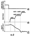
Figure 8 is a graphical representation of example operational values for theFigure 7 braking system; -
Figure 9 is a schematic view of still another electromagnetic brake embodiment of a braking system for an elevator system; -
Figure 10 is a graphical representation of example operational values for theFigure 9 braking system; -
Figure 11 is a schematic diagram of a braking control circuit for an elevator system; and -
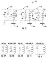
Figure 12-16 are schematic diagrams of a portion of alternate braking control circuits for an elevator system. -
Figure 1 schematically illustrates anelevator system 10. Theelevator system 10 includes anelevator car 12 located in ahoistway 14. Thehoistway 14 includes one ormore guide rails 16 interactive with one ormore guide shoes 18 of theelevator car 12 to guide theelevator car 12 along thehoistway 14. Asuspension member 20, typically a rope and/or a belt, suspends theelevator car 12 in thehoistway 14. It should be appreciated that although particular systems are separately defined, each or any of the systems can include otherwise combined or separated via hardware and/or software. It should also be appreciated that although onesuspension member 20 is shown,multiple suspension members 20 may be utilized. Thesuspension member 20 is routed over one ormore sheaves 22 thence to acounterweight 24 which may also be disposed in thehoistway 14. One or more of the sheaves may be adrive sheave 26, operably connected to amachine 28 to control theelevator car 12 along thehoistway 14. - The
elevator system 10 includes abrake system 30 disposed, in one embodiment, at thedrive sheave 26 to halt rotation of thedrive sheave 26 and thus stop movement of theelevator car 12 in response to certain select conditions such as a power failure to theelevator system 10 or other emergency stop (E-stop) situations. While in the described embodiments thebrake system 30 is disposed at thedrive sheave 26, it is to be appreciated that in other embodiments thebrake system 30 may be located at theelevator car 12 and is configured to engage theguide rail 16 thus stopping motion of theelevator car 12 in thehoistway 14. - In this embodiment, the
brake system 30 is an electromagnetic brake that is normally in an open position when supplied with electrical power and the electromagnetic coils thereof are energized. This open position permits free travel of theelevator car 12. When, however, the supply of electrical power to the electromagnetic coils ceases, thebrake system 30 engages and safely stops theelevator car 12. Intypical elevator systems 10, theelectromagnetic brake system 30 quickly stops theelevator car 12, but such rapid deceleration of theelevator car 12 may result in passenger discomfort. - With reference to
Figures 2 and 3 , two cases during operation of theelevator system 10 where thebrake 30 may be applied to stop theelevator car 12 are schematically illustrated.Figure 2 schematically illustrates the case where theelevator car 12 is lighter than the counterweight and is travelling upward. In this case, when thebrake system 30 is applied, abrake friction force 32 and agravity force 34 are in opposite directions. This has the effect of lowering a deceleration rate of theelevator car 12.Figure 3 schematically illustrates the case where theelevator car 12 is lighter than the counterweight and is travelling downward when thebrake system 30 is applied. In this case, thebrake friction force 32 and thegravity force 34 are in the same direction, effectively increasing the deceleration rate of theelevator car 12 once thebrake system 30 is applied. In this case it may be desirable to delay application of full brake torque by, in some embodiments, several hundred milliseconds, and soften the application of full brake torque to reduce the deceleration rate of theelevator car 12. This also facilitates reduction of the potential for slippage of thesuspension member 20. - With reference to
Figures 4-5 , certain regulatory regimes may require electro-mechanical brakes to meet the following code requirements: - 1- The brake system shall stop the car traveling down with 125% load; and
- 2- All mechanical components of the brake shall be installed in at least two sets such that if one set fails (N-1), the remainder shall stop and hold the car traveling down with 100% load.
- In one embodiment, the
brake system 30 includes a multiple of sequentially operated brake segments 40a-40c (three segments shown in this example). Each brake segment 40a-40c is separately operable and designed in relationship to the other brake segments to meet the desired code requirements. The multiple of sequentially operated brake segments 40a-40c facilitate emergency stop performance by increasing the time of which the code required brake torque is applied which, as a result, the deceleration of an E-stop is smoother and more controlled which is particularly advantageous in territories with frequent power interruptions. - In one
example elevator system 10, an empty car weighs 1000kg with a duty load of 2000kg and a counterweight that weighs 2000kg at a 0.5 overbalance. This results in a potential full car imbalance load of 1000kg and a code requirement of 1500kg for the 125% load and 1000kg load stop for N-1 segments (Figure 5 ). In this example, each brake segment 40a, 40b, 40c of a 3-segment brake accommodates 500kg to meetcode requirement 1 of 1500kg. That is, operation of all brake segments 40a, 40b, 40c stop 125% rated load (1500kg) to meetcode requirement 1, while operation of N-1 segments 40a, 40b stop 100% load (1000kg) to meetcode requirement 2. This essentially softens the application of full brake torque to reduce the deceleration rate of theelevator car 12. This advantageously compares to a two-segment brake in which each of the two segments must provide 100% of the rated load (1000kg) to meetcode requirement 2 and thus results in a total brake torque of 2000kg when both segments are operational. In other words,code requirement 2 for a two-segment brake results in a relatively high rate of deceleration during an emergency stop event when both segments are properly operational - which is typical. Notably, for a 4-segment and 5-segment brake,code requirement 1 necessarily controls to meet the 125% rated load requirement (1500kg) (Figure 5 ). - With continued reference to
Figure 4 , each of the multiple of sequentially operated brake segments 40a-40c includes a separately operable electromagnetic coil 50a-50n that drives an associated brake caliper 52a-52c to control the timing and rate of the brake torque applied to asingle brake disc 54. That is, each brake caliper 52a-52c is non-circular and interacts with a respective sector of thesingle brake disc 54. Each electromagnetic coil 50a-50c may be oval, curved, bean-shaped, circular, etc., and operates to control its respective brake caliper 52a-52c. - With reference to
Figure 6 , each of the multiple of sequentially operated brake segments 40a-40c (three segments shown in this example) may alternatively include separate brake subsystems 42a-42c. Each separate brake subsystems 42a-42c include a brake disc 44a-44c, an electromagnetic coil 46a-46c, and an associated brake caliper 48a-48c. That is, each brake subsystems 42a-42c is self contained and separately mounted along an axis A on thedrive sheave 26. - With reference to
Figure 7 , another embodiment of thebrake system 30 includes three sequentially operated brake segments 60a-60c that each include a separately operable electromagnetic coil 62a-62c (illustrated schematically) that drives an associated brake caliper 64a-64c to control the timing and rate of the brake torque applied to asingle brake disc 66. In this embodiment, each brake segment 60a-60c is about equivalent in size, while each electromagnetic coil 62a-62c is different so as to vary the response time of the three sequentially operated brake segments 60a-60c. That is, each brake segments 60a-60c applies about equal brake torque but is released at a different time from the emergency stop (E-stop) initiation. The difference in the electromagnetic coil 62a-62c may be achieved by, for example, different characteristics in the coil design such as a number of coil turns, coil diameter, coil material, coil size, gap size, brake voltages, plate/housing materials, and/or combinations thereof. It should be appreciated that various characteristics may be defined to differentiate operation of the electromagnetic coil 62a-62c. - In this embodiment, the first brake segment 60a drops relatively rapidly which almost immediately results in the rapid application of about 1/3 of the total brake torque. This rapid application of about 1/3 of the total brake torque prevents an over-speed condition (
Figure 7 ). Then, the second and third electromagnetic coils 62b, 62c are sized to sequentially release the associated brake segments 60b, 60c to complete a relatively smooth stop. - With reference to
Figure 8 , upon initiation of an emergency stop (E-stop) operation, the first brake segment 60a rapidly releases to prevent over-speed. Notably, the velocity of theelevator car 12 slightly increases but an over speed condition does not occur due to the rapid drop off of the first electromagnetic coil 62a. Then, the second and third electromagnetic coils 62b, 62c drop sequentially thereafter to extend the brake activation time to achieve a relatively smooth stop. This sequential operation facilitates passive reduction to otherwise relatively harsh E-stops, complies with elevator codes, and requires no supplemental external power. - With reference to
Figure 9 , another embodiment of thebrake system 30 includes an auxiliary brake segment 80a and two main brake segments 80b, 80c that each include a separately operable electromagnetic coil 82a-82c and an associated brake caliper 84a-84c to control the timing and rate of the brake torque application to a single brake disc 86. In this embodiment, the auxiliary brake segment 80a is significantly smaller than that of the main brake segments 80b, 80c. In this example, the auxiliary brake segment 80a is an about 30 degree segment, and each of the main brake segment 80b, 80c are about 115 degrees. The auxiliary brake segment 80a may be sized just large enough to prevent an over speed condition. The over speed condition in one example is about 15% of a nominal e.g. 1 meter per second nominal speed. - With reference to
Figure 10 , upon initiation of an emergency stop (E-stop) operation, the auxiliary brake segment 80a relatively rapidly applies a brake torque sufficient to prevent over-speed. Notably, the velocity of theelevator car 12 may slightly increase but an over speed issue does not occur due to the rapid application of the auxiliary brake segment 80a. Then, the second and third brake segments 80b, 80c drop essentially simultaneously thereafter to achieve a relatively smooth stop as compared to a conventional E-stop. This operation addresses local code challenges to a sequential brake drop (Figures 7 and8 ) yet still facilitates passive reduction to otherwise relatively harsh E-stops. - With reference to
Figure 11 , another embodiment of thebrake system 30 includes abrake control circuit 100 to control operation of each of a multiple of brake segments 110a-110c (three segments shown in this example) of thebrake system 30 and thereby passively sequence the brake drop of each brake segment 110a-110c to slow the deceleration rate in an E-stop event. Various regulatory agencies require electromechanical brake systems to become effective without supplementary delay after opening the brake release circuit. Diode and capacitor elements are not considered by the regulatory agencies to constitute a supplemental delay. - The
brake control circuit 100 includes an electromagnetic coil 112a-112c, a snubber network 114a-114c, and a latching relay 116a-116c for each respective brake segment 110a-110c. It should be appreciated that although three segments are illustrated in this example, any number of segments will benefit herefrom. - The snubber networks 114a-114c are electrically arranged so that the electromagnetic coils 112a-112c are sequenced in time to slow a deceleration rate for an E-stop event. For example, the snubber network 114a may include a
surge absorbing component 116, such a Zener diode, a Metal Oxide Varistor (MOV) a Transorb, or other component, in series with anotherdiode 118 for relatively fast operation for the electromagnetic coil 112a of the brake segment 110a; the snubber network 114b may be aresistor 120 in series with adiode 122 for the next sequential operation of the second electromagnetic coil 112b of the second brake segment 110b; and the snubber network 114c may include acapacitor 124 in parallel with adiode 126 for the next sequential operation of the third electromagnetic coil 112c of the third brake segment 110c. - Upon initiation of an E-stop operation after loss of power, the snubber network 114a minimally prolongs current flow for relatively fast operation of the electromagnetic coil 112a of the brake segment 110a. The brake segment 110a thereby readily rapidly applies a brake torque sufficient to prevent over-speed. Then, the second and third electromagnetic coils 112b, 112c drop in accordance with the brake drop time provided by the respective snubber networks 114b, 114c, to complete a relatively smooth E-stop. This operation addresses local code challenges of a sequential brake drop yet still facilitates passive reduction to otherwise relatively harsh E-stops.
- It should be appreciated that the snubber networks 114ab, 114c may be readily defined to provide the desired response for each brake segment 110a-110c. Alternative embodiments of the snubber networks are schematically illustrated in
Figures 12-16 to provide a range of brake drop times such as a relatively fast Zener diode snubber network arrangement (Figure 12 ); an adjustable speed snubber network arrangement with a variable resistor (Figure 13 ); a slow snubber network arrangement (Figure 14 ); an ultra slow snubber network arrangement with a capacitor and diode in parallel (Figure 15 ); and an ultra slow snubber network arrangement with a diode and a coil or inductor in series (Figure 16 ). It should be appreciated that various snubber networks, and various combinations thereof may be utilized to control the actuation sequence of each brake segment 110a-110c. - The latching relay 116a-116c of each brake segment 110a-110c may be simultaneously closed in an E-stop event such that a sequential brake drop of all brake segments occurs. Alternatively, only one or more the latching relay 116a-116c are closed such that the particular latching relay 116a-116c are set to a selected position at a beginning of an
elevator car 12 run, based on, for example, a direction ofelevator car 12 travel such as regen or motoring, and/or load imbalance between theelevator car 12 and thecounterweight 24. That is, only particular brake segments 110a-110c may be set for a particular elevator run. While the latching relays 116a-116c are illustrated and described herein, it is to be appreciated that other switching mechanisms may be utilized in thebrake control circuit 100. For example, in other embodiments a normal, non-latching relay or an electronic switch such as a mofset may be used. Further, an additional relay may be utilized in conjunction with the mofset to "latch" the mofset. This operation addresses local code challenges of a sequential brake drop yet still facilitates passive reduction to otherwise relatively harsh E-stops. - The use of the terms "a," "an," "the," and similar references in the context of description (especially in the context of the following claims) are to be construed to cover both the singular and the plural, unless otherwise indicated herein or specifically contradicted by context. The modifier "about" used in connection with a quantity is inclusive of the stated value and has the meaning dictated by the context (e.g., it includes the degree of error associated with measurement of the particular quantity). All ranges disclosed herein are inclusive of the endpoints, and the endpoints are independently combinable with each other.
- Although the different non-limiting embodiments have specific illustrated components, the embodiments of this invention are not limited to those particular combinations. It is possible to use some of the components or features from any of the non-limiting embodiments in combination with features or components from any of the other non-limiting embodiments.
- It should be appreciated that like reference numerals identify corresponding or similar elements throughout the several drawings. It should also be appreciated that although a particular component arrangement is disclosed in the illustrated embodiment, other arrangements will benefit herefrom.
- Although particular step sequences are shown, described, and claimed, it should be understood that steps may be performed in any order, separated or combined unless otherwise indicated and will still benefit from the present disclosure.
- The foregoing description is exemplary rather than defined by the limitations within. Various non-limiting embodiments are disclosed herein, however, one of ordinary skill in the art would recognize that various modifications and variations in light of the above teachings will fall within the scope of the appended claims. It is therefore to be understood that within the scope of the appended claims, the disclosure may be practiced other than as specifically described. For that reason the appended claims should be studied to determine true scope and content.
Claims (15)
- A brake system for an elevator car comprising:a multiple of sequentially operated brake segments to control a timing and a rate of brake torque for deceleration of the elevator car, wherein the multiple of sequentially operated brake segments include at least three brake segments.
- The system as recited in claim 1, wherein the multiple of sequentially operated brake segments includes only three brake segments.
- The system as recited in claims 1 or 2, wherein each of the multiple of sequentially operated brake segments includes an electromagnetic coil that controls the timing and the rate of brake torque for that brake segment.
- The system as recited in claim 3, wherein each of the electromagnetic coils operates to control a respective brake caliper, and preferably wherein each of the respective brake calipers interacts with a respective brake disc
- The system as recited in any preceding claim, wherein each of the multiple of sequentially operated brake segments are concentrically arranged within a common plane.
- The system as recited in any preceding claim, wherein each of the multiple of sequentially operated brake segments are circumferentially arranged or axially arranged.
- The system as recited in any preceding claim, wherein the multiple of sequentially operated brake segments is operable to stop 125% of a rated load of the elevator car, and preferably wherein an N-1 number of the multiple of sequentially operated brake segments, is operable to stop 100% of the rated load of the elevator car wherein N is the total number of brake segments.
- A brake system for an elevator car as claimed in any preceding claim, wherein said multiple of sequentially operated brake segments comprises:a first brake segment;a second brake segment sequentially operable subsequent to the first brake segment; anda third brake segment sequentially operable subsequent to the second brake segment, and wherein the sequential operation of the first, second, and the third brake segment is operable to control a timing and a rate of brake torque for deceleration of the elevator car.
- The system as recited in claim 8, wherein the first, the second, and the third brake segment each include an electromagnetic coil operable to control a respective brake caliper on a respective brake disc.
- The system as recited in claim 8, wherein the first, the second, and the third brake segment each include an electromagnetic coil operable to control a respective brake caliper on a single brake disc.
- The system as recited in any of claims 8-10, wherein the first, the second, and the third brake segment are sequentially operated to stop 125% of a rated load of the elevator car, and preferably wherein two of the first, the second, and the third brake segments are operable to stop 100% of the load of the elevator car.
- A method of engaging an electromagnetic brake for an elevator system comprising:sequentially controlling a multiple of brake segments to control a timing and a rate of brake torque for deceleration of the elevator car.
- The method as recited in Claim 12, wherein the multiple of brake segments are sequentially operated to stop 125% of a rated load of the elevator car.
- The method as recited in Claim 12 or 13, further comprising sequentially operating the multiple of brake segments as a first, a second, and a third brake segment.
- The method as recited in any of Claims 12-14, further comprising sequentially operating the multiple of brake with respect to a single brake disc.
Applications Claiming Priority (1)
| Application Number | Priority Date | Filing Date | Title |
|---|---|---|---|
| US201562185812P | 2015-06-29 | 2015-06-29 |
Publications (2)
| Publication Number | Publication Date |
|---|---|
| EP3112305A1 true EP3112305A1 (en) | 2017-01-04 |
| EP3112305B1 EP3112305B1 (en) | 2024-05-15 |
Family
ID=56296613
Family Applications (1)
| Application Number | Title | Priority Date | Filing Date |
|---|---|---|---|
| EP16176961.7A Active EP3112305B1 (en) | 2015-06-29 | 2016-06-29 | Electromagnetic brake system for elevator application |
Country Status (5)
| Country | Link |
|---|---|
| US (1) | US10442659B2 (en) |
| EP (1) | EP3112305B1 (en) |
| KR (1) | KR102568334B1 (en) |
| CN (2) | CN114408698A (en) |
| ES (1) | ES2987673T3 (en) |
Cited By (1)
| Publication number | Priority date | Publication date | Assignee | Title |
|---|---|---|---|---|
| EP3569547A1 (en) * | 2018-05-15 | 2019-11-20 | Otis Elevator Company | Electronic safety actuator for lifting a safety wedge of an elevator |
Families Citing this family (6)
| Publication number | Priority date | Publication date | Assignee | Title |
|---|---|---|---|---|
| BR112017002055B1 (en) * | 2014-08-07 | 2022-07-19 | Inventio Ag | LIFT SYSTEM, BRAKE SYSTEM FOR AN LIFT SYSTEM AND METHOD FOR CONTROLLING A BRAKE SYSTEM OF AN LIFT SYSTEM |
| US10450162B2 (en) * | 2015-06-29 | 2019-10-22 | Otis Elevator Company | Electromagnetic brake control circuitry for elevator application |
| US10479645B2 (en) * | 2015-06-29 | 2019-11-19 | Otis Elevator Company | Electromagnetic brake system for elevator application |
| US10207896B2 (en) * | 2017-01-30 | 2019-02-19 | Otis Elevator Company | Elevator machine brake control |
| CN109516336B (en) * | 2018-12-29 | 2024-09-13 | 刘英辉 | Linear drive device, safety tongs device and control method of elevator system |
| US12110207B2 (en) * | 2019-11-14 | 2024-10-08 | Otis Elevator Company | Electromagnetic brake configured to slow deceleration rate of passenger conveyer during braking |
Citations (3)
| Publication number | Priority date | Publication date | Assignee | Title |
|---|---|---|---|---|
| EP1918239A1 (en) * | 2005-08-25 | 2008-05-07 | Mitsubishi Denki Kabushiki Kaisha | Elevator device |
| EP2474753A2 (en) * | 2011-01-07 | 2012-07-11 | Kabushiki Kaisha Yaskawa Denki | Electromagnetic brake, rotating electrical machine, and elevator |
| WO2016110329A1 (en) * | 2015-01-09 | 2016-07-14 | Thyssenkrupp Elevator Ag | Sequential electromechanical brake with advanced emergency tripping |
Family Cites Families (51)
| Publication number | Priority date | Publication date | Assignee | Title |
|---|---|---|---|---|
| FR550133A (en) | 1921-08-16 | 1923-02-27 | Self-centering brake | |
| US2295503A (en) | 1940-09-19 | 1942-09-08 | Hydraulic Brake Co | Brake |
| GB582529A (en) | 1943-03-29 | 1946-11-20 | Dumore Company | Braking mechanism |
| GB703917A (en) | 1950-03-28 | 1954-02-10 | Wilhelm Stoeckicht | Improvements in brakes and clutches actuated by a liquid under pressure or compressed air |
| US2695697A (en) | 1950-03-28 | 1954-11-30 | Wilhelm G Stoeckicht | Braking and coupling device actuated by a liquid under pressure or compressed air |
| GB845241A (en) | 1957-12-02 | 1960-08-17 | Gen Electric Co Ltd | Improvements in or relating to waveguides and methods of bending waveguides |
| DE1675145B1 (en) | 1968-03-01 | 1971-07-29 | Heemaf Ska Motorenwerk | INNER DRUM BRAKE |
| FR2341513A1 (en) | 1976-02-23 | 1977-09-16 | David Pierre | SAFETY BRAKING DEVICE FOR MOBILE CREW ALONG A SURFACE, ESPECIALLY FOR ELEVATOR CABIN |
| US4170278A (en) | 1978-04-18 | 1979-10-09 | Schubert Karl P | Electromagnetic brake |
| DE8005138U1 (en) | 1980-02-26 | 1980-11-06 | Friedrich Deckel Ag, 8000 Muenchen | SHAFT BRAKE |
| CN2039368U (en) | 1988-03-10 | 1989-06-14 | 岳阳起重电磁铁厂 | Electromagnetic brake |
| US4975627A (en) * | 1988-08-15 | 1990-12-04 | Otis Elevator Company | Brake sequenced elevator motor speed control |
| JPH07102949B2 (en) | 1989-09-28 | 1995-11-08 | 三菱電機株式会社 | Elevator braking system |
| JPH03121238U (en) | 1990-03-26 | 1991-12-12 | ||
| CN2073963U (en) | 1990-05-29 | 1991-03-27 | 振吉电化厂股份有限公司 | Electromagnetic brake |
| JP2539087B2 (en) | 1990-09-03 | 1996-10-02 | 株式会社日立製作所 | Electromagnetic disk brake |
| JP2553452B2 (en) | 1993-07-07 | 1996-11-13 | 西部電機株式会社 | Equipment for loading goods |
| JP2606575Y2 (en) | 1993-10-12 | 2000-11-27 | グローリー工業株式会社 | Product storage department of vending machine |
| GB9422056D0 (en) * | 1994-11-02 | 1994-12-21 | Alcon Components Ltd | Racing disc brake |
| US6166500A (en) * | 1997-07-18 | 2000-12-26 | Siemens Canada Limited | Actively controlled regenerative snubber for unipolar brushless DC motors |
| FI111241B (en) | 1999-09-23 | 2003-06-30 | Kone Corp | Procedure for braking a drive pulley lift, drive pulley lift and use of a backup power source |
| DK1294631T3 (en) | 2000-05-25 | 2004-11-22 | Inventio Ag | Brake device for an elevator |
| DE10128846A1 (en) | 2001-06-15 | 2003-01-09 | Bosch Gmbh Robert | Band brake for road vehicle has brake band with electromagnet movable in peripheral direction that is attracted to brake drum when current is applied, thereby tightening band around drum |
| EP1334946B1 (en) | 2002-02-08 | 2008-04-02 | Inventio Ag | Internal drum brake for a lift drive |
| DE20206022U1 (en) | 2002-04-12 | 2003-08-21 | Schunk GmbH & Co. KG Fabrik für Spann- und Greifwerkzeuge, 74348 Lauffen | locking device |
| JPWO2004050527A1 (en) | 2002-12-04 | 2006-03-30 | 三菱電機株式会社 | Brake mechanism of hoisting machine |
| FI20031647A0 (en) * | 2003-11-12 | 2003-11-12 | Kone Corp | Lift brake control circuit |
| US7048096B2 (en) | 2003-12-08 | 2006-05-23 | Russell Ozechowski | Incremental braking apparatus and method of braking |
| US20060260886A1 (en) * | 2004-02-05 | 2006-11-23 | Erlston Lester J | Coaxial helical brake and method of braking in lightweight brake configuration |
| FI119877B (en) * | 2005-08-19 | 2009-04-30 | Kone Corp | Elevator security |
| US7669697B2 (en) * | 2006-02-01 | 2010-03-02 | Mitsubishi Electric Corporation | Elevator apparatus |
| KR100931430B1 (en) * | 2006-03-20 | 2009-12-11 | 미쓰비시덴키 가부시키가이샤 | Elevator device |
| DE102006043999A1 (en) | 2006-09-19 | 2008-04-03 | Siemens Ag | Brake, especially a servobrake, comprises annularly arranged friction elements that can be moved in a radial direction and pressed against/released from the friction surface of an element to be braked by an actuator |
| KR101130926B1 (en) * | 2007-03-27 | 2012-03-29 | 미쓰비시덴키 가부시키가이샤 | Brake device for elevator |
| JP5070912B2 (en) | 2007-04-10 | 2012-11-14 | 株式会社日立製作所 | Elevator hoisting machine |
| EP2141109A4 (en) * | 2007-04-26 | 2013-10-30 | Mitsubishi Electric Corp | ELEVATOR DEVICE |
| US8783423B2 (en) * | 2007-12-21 | 2014-07-22 | Honda Motor Co., Ltd. | Multi-part multi-stage brakes |
| RU2455540C2 (en) | 2008-02-12 | 2012-07-10 | Владимир Александрович Парамошко | Braking device |
| KR101121826B1 (en) * | 2008-04-15 | 2012-03-22 | 미쓰비시덴키 가부시키가이샤 | Elevator device |
| EP2447201A1 (en) * | 2009-06-22 | 2012-05-02 | Mitsubishi Electric Corporation | Elevator device |
| DE102009048822A1 (en) * | 2009-10-09 | 2011-04-14 | Siemens Aktiengesellschaft | Transport system with electromagnetic brake |
| JP2011105455A (en) * | 2009-11-17 | 2011-06-02 | Mitsubishi Electric Corp | Elevator device |
| EP2332872A1 (en) * | 2009-12-11 | 2011-06-15 | Inventio AG | Selective elevator braking during emergency stop |
| EP2670695B1 (en) * | 2011-02-04 | 2022-09-07 | Otis Elevator Company | Stop sequencing for braking device |
| FI123506B (en) * | 2012-05-31 | 2013-06-14 | Kone Corp | Elevator control and elevator safety arrangement |
| CN104583109B (en) * | 2012-08-02 | 2016-09-21 | 奥的斯电梯公司 | Hydraulic braking system for elevators |
| US9140323B2 (en) | 2013-03-13 | 2015-09-22 | Eaton Corporation | Drum and constricting drum assembly |
| BR112015025884B1 (en) * | 2013-04-12 | 2022-08-02 | Wabtec Holding Corp | BRAKE DISC, AND BRAKE ASSEMBLY |
| ES2622383T3 (en) | 2013-06-13 | 2017-07-06 | Inventio Ag | Braking procedure for a people transport installation, brake control for carrying out the braking procedure and people transport installation with a brake control |
| US10479645B2 (en) | 2015-06-29 | 2019-11-19 | Otis Elevator Company | Electromagnetic brake system for elevator application |
| KR102666801B1 (en) * | 2015-09-10 | 2024-05-20 | 오티스 엘리베이터 컴파니 | Elevator brake assembly |
-
2016
- 2016-06-27 US US15/193,436 patent/US10442659B2/en active Active
- 2016-06-28 CN CN202210116345.8A patent/CN114408698A/en active Pending
- 2016-06-28 CN CN201610489053.3A patent/CN106276673A/en active Pending
- 2016-06-29 KR KR1020160081917A patent/KR102568334B1/en active Active
- 2016-06-29 ES ES16176961T patent/ES2987673T3/en active Active
- 2016-06-29 EP EP16176961.7A patent/EP3112305B1/en active Active
Patent Citations (3)
| Publication number | Priority date | Publication date | Assignee | Title |
|---|---|---|---|---|
| EP1918239A1 (en) * | 2005-08-25 | 2008-05-07 | Mitsubishi Denki Kabushiki Kaisha | Elevator device |
| EP2474753A2 (en) * | 2011-01-07 | 2012-07-11 | Kabushiki Kaisha Yaskawa Denki | Electromagnetic brake, rotating electrical machine, and elevator |
| WO2016110329A1 (en) * | 2015-01-09 | 2016-07-14 | Thyssenkrupp Elevator Ag | Sequential electromechanical brake with advanced emergency tripping |
Cited By (2)
| Publication number | Priority date | Publication date | Assignee | Title |
|---|---|---|---|---|
| EP3569547A1 (en) * | 2018-05-15 | 2019-11-20 | Otis Elevator Company | Electronic safety actuator for lifting a safety wedge of an elevator |
| US11078045B2 (en) | 2018-05-15 | 2021-08-03 | Otis Elevator Company | Electronic safety actuator for lifting a safety wedge of an elevator |
Also Published As
| Publication number | Publication date |
|---|---|
| ES2987673T3 (en) | 2024-11-15 |
| CN114408698A (en) | 2022-04-29 |
| US20160376123A1 (en) | 2016-12-29 |
| US10442659B2 (en) | 2019-10-15 |
| CN106276673A (en) | 2017-01-04 |
| KR102568334B1 (en) | 2023-08-18 |
| EP3112305B1 (en) | 2024-05-15 |
| KR20170002331A (en) | 2017-01-06 |
Similar Documents
| Publication | Publication Date | Title |
|---|---|---|
| EP3112305B1 (en) | Electromagnetic brake system for elevator application | |
| EP3112303B1 (en) | Electromagnetic brake system for elevator application | |
| CN109573760B (en) | Emergency braking for a drive system | |
| AU2007285644B2 (en) | Elevator system | |
| US11897725B2 (en) | Adjustment of drop rate of elevator car with electromagnetic brake system | |
| EP2670695B1 (en) | Stop sequencing for braking device | |
| KR20140035314A (en) | Elevator safety circuit | |
| EP2763925A1 (en) | Elevator brake control | |
| EP3112304B1 (en) | Electromagnetic brake control circuitry for elevator application | |
| US20140202798A1 (en) | Elevator monitoring arrangement and method for monitoring an elevator | |
| US11597633B2 (en) | Elevator safety brake, elevator and method for testing elevator safety brakes | |
| JP2021134042A (en) | Elevator emergency stop test method and elevator emergency stop test power supply | |
| EP3689804A1 (en) | Elevator safety brake, elevator and method for testing elevator safety brakes | |
| EP4457169A1 (en) | Stationary mechanical brake for linear motor elevators | |
| HK1133416B (en) | Elevator system | |
| WO2017160716A1 (en) | Management of mutiple coil brake for elevator system | |
| HK1208896B (en) | Brake | |
| HK1199437B (en) | Elevator monitoring arrangement and method for monitoring an elevator |
Legal Events
| Date | Code | Title | Description |
|---|---|---|---|
| PUAI | Public reference made under article 153(3) epc to a published international application that has entered the european phase |
Free format text: ORIGINAL CODE: 0009012 |
|
| STAA | Information on the status of an ep patent application or granted ep patent |
Free format text: STATUS: THE APPLICATION HAS BEEN PUBLISHED |
|
| AK | Designated contracting states |
Kind code of ref document: A1 Designated state(s): AL AT BE BG CH CY CZ DE DK EE ES FI FR GB GR HR HU IE IS IT LI LT LU LV MC MK MT NL NO PL PT RO RS SE SI SK SM TR |
|
| AX | Request for extension of the european patent |
Extension state: BA ME |
|
| STAA | Information on the status of an ep patent application or granted ep patent |
Free format text: STATUS: REQUEST FOR EXAMINATION WAS MADE |
|
| 17P | Request for examination filed |
Effective date: 20170704 |
|
| RBV | Designated contracting states (corrected) |
Designated state(s): AL AT BE BG CH CY CZ DE DK EE ES FI FR GB GR HR HU IE IS IT LI LT LU LV MC MK MT NL NO PL PT RO RS SE SI SK SM TR |
|
| RAP1 | Party data changed (applicant data changed or rights of an application transferred) |
Owner name: OTIS ELEVATOR COMPANY |
|
| STAA | Information on the status of an ep patent application or granted ep patent |
Free format text: STATUS: EXAMINATION IS IN PROGRESS |
|
| 17Q | First examination report despatched |
Effective date: 20201111 |
|
| RIC1 | Information provided on ipc code assigned before grant |
Ipc: F16D 55/22 20060101ALI20231031BHEP Ipc: B66B 5/02 20060101ALI20231031BHEP Ipc: B66D 5/30 20060101ALI20231031BHEP Ipc: B66B 1/32 20060101AFI20231031BHEP |
|
| GRAP | Despatch of communication of intention to grant a patent |
Free format text: ORIGINAL CODE: EPIDOSNIGR1 |
|
| STAA | Information on the status of an ep patent application or granted ep patent |
Free format text: STATUS: GRANT OF PATENT IS INTENDED |
|
| INTG | Intention to grant announced |
Effective date: 20231212 |
|
| GRAS | Grant fee paid |
Free format text: ORIGINAL CODE: EPIDOSNIGR3 |
|
| GRAA | (expected) grant |
Free format text: ORIGINAL CODE: 0009210 |
|
| STAA | Information on the status of an ep patent application or granted ep patent |
Free format text: STATUS: THE PATENT HAS BEEN GRANTED |
|
| AK | Designated contracting states |
Kind code of ref document: B1 Designated state(s): AL AT BE BG CH CY CZ DE DK EE ES FI FR GB GR HR HU IE IS IT LI LT LU LV MC MK MT NL NO PL PT RO RS SE SI SK SM TR |
|
| REG | Reference to a national code |
Ref country code: CH Ref legal event code: EP Ref country code: GB Ref legal event code: FG4D |
|
| REG | Reference to a national code |
Ref country code: DE Ref legal event code: R096 Ref document number: 602016087500 Country of ref document: DE |
|
| REG | Reference to a national code |
Ref country code: IE Ref legal event code: FG4D |
|
| PGFP | Annual fee paid to national office [announced via postgrant information from national office to epo] |
Ref country code: GB Payment date: 20240620 Year of fee payment: 9 |
|
| PGFP | Annual fee paid to national office [announced via postgrant information from national office to epo] |
Ref country code: FR Payment date: 20240619 Year of fee payment: 9 |
|
| REG | Reference to a national code |
Ref country code: LT Ref legal event code: MG9D |
|
| REG | Reference to a national code |
Ref country code: NL Ref legal event code: MP Effective date: 20240515 |
|
| PG25 | Lapsed in a contracting state [announced via postgrant information from national office to epo] |
Ref country code: IS Free format text: LAPSE BECAUSE OF FAILURE TO SUBMIT A TRANSLATION OF THE DESCRIPTION OR TO PAY THE FEE WITHIN THE PRESCRIBED TIME-LIMIT Effective date: 20240915 |
|
| PG25 | Lapsed in a contracting state [announced via postgrant information from national office to epo] |
Ref country code: BG Free format text: LAPSE BECAUSE OF FAILURE TO SUBMIT A TRANSLATION OF THE DESCRIPTION OR TO PAY THE FEE WITHIN THE PRESCRIBED TIME-LIMIT Effective date: 20240515 |
|
| PG25 | Lapsed in a contracting state [announced via postgrant information from national office to epo] |
Ref country code: HR Free format text: LAPSE BECAUSE OF FAILURE TO SUBMIT A TRANSLATION OF THE DESCRIPTION OR TO PAY THE FEE WITHIN THE PRESCRIBED TIME-LIMIT Effective date: 20240515 Ref country code: FI Free format text: LAPSE BECAUSE OF FAILURE TO SUBMIT A TRANSLATION OF THE DESCRIPTION OR TO PAY THE FEE WITHIN THE PRESCRIBED TIME-LIMIT Effective date: 20240515 |
|
| PG25 | Lapsed in a contracting state [announced via postgrant information from national office to epo] |
Ref country code: GR Free format text: LAPSE BECAUSE OF FAILURE TO SUBMIT A TRANSLATION OF THE DESCRIPTION OR TO PAY THE FEE WITHIN THE PRESCRIBED TIME-LIMIT Effective date: 20240816 |
|
| PG25 | Lapsed in a contracting state [announced via postgrant information from national office to epo] |
Ref country code: PT Free format text: LAPSE BECAUSE OF FAILURE TO SUBMIT A TRANSLATION OF THE DESCRIPTION OR TO PAY THE FEE WITHIN THE PRESCRIBED TIME-LIMIT Effective date: 20240916 |
|
| REG | Reference to a national code |
Ref country code: AT Ref legal event code: MK05 Ref document number: 1686796 Country of ref document: AT Kind code of ref document: T Effective date: 20240515 |
|
| PG25 | Lapsed in a contracting state [announced via postgrant information from national office to epo] |
Ref country code: NL Free format text: LAPSE BECAUSE OF FAILURE TO SUBMIT A TRANSLATION OF THE DESCRIPTION OR TO PAY THE FEE WITHIN THE PRESCRIBED TIME-LIMIT Effective date: 20240515 |
|
| PGFP | Annual fee paid to national office [announced via postgrant information from national office to epo] |
Ref country code: ES Payment date: 20240703 Year of fee payment: 9 |
|
| PG25 | Lapsed in a contracting state [announced via postgrant information from national office to epo] |
Ref country code: AT Free format text: LAPSE BECAUSE OF FAILURE TO SUBMIT A TRANSLATION OF THE DESCRIPTION OR TO PAY THE FEE WITHIN THE PRESCRIBED TIME-LIMIT Effective date: 20240515 |
|
| PG25 | Lapsed in a contracting state [announced via postgrant information from national office to epo] |
Ref country code: PL Free format text: LAPSE BECAUSE OF FAILURE TO SUBMIT A TRANSLATION OF THE DESCRIPTION OR TO PAY THE FEE WITHIN THE PRESCRIBED TIME-LIMIT Effective date: 20240515 |
|
| PG25 | Lapsed in a contracting state [announced via postgrant information from national office to epo] |
Ref country code: LV Free format text: LAPSE BECAUSE OF FAILURE TO SUBMIT A TRANSLATION OF THE DESCRIPTION OR TO PAY THE FEE WITHIN THE PRESCRIBED TIME-LIMIT Effective date: 20240515 |
|
| PG25 | Lapsed in a contracting state [announced via postgrant information from national office to epo] |
Ref country code: PT Free format text: LAPSE BECAUSE OF FAILURE TO SUBMIT A TRANSLATION OF THE DESCRIPTION OR TO PAY THE FEE WITHIN THE PRESCRIBED TIME-LIMIT Effective date: 20240916 Ref country code: PL Free format text: LAPSE BECAUSE OF FAILURE TO SUBMIT A TRANSLATION OF THE DESCRIPTION OR TO PAY THE FEE WITHIN THE PRESCRIBED TIME-LIMIT Effective date: 20240515 Ref country code: NO Free format text: LAPSE BECAUSE OF FAILURE TO SUBMIT A TRANSLATION OF THE DESCRIPTION OR TO PAY THE FEE WITHIN THE PRESCRIBED TIME-LIMIT Effective date: 20240815 Ref country code: NL Free format text: LAPSE BECAUSE OF FAILURE TO SUBMIT A TRANSLATION OF THE DESCRIPTION OR TO PAY THE FEE WITHIN THE PRESCRIBED TIME-LIMIT Effective date: 20240515 Ref country code: LV Free format text: LAPSE BECAUSE OF FAILURE TO SUBMIT A TRANSLATION OF THE DESCRIPTION OR TO PAY THE FEE WITHIN THE PRESCRIBED TIME-LIMIT Effective date: 20240515 Ref country code: IS Free format text: LAPSE BECAUSE OF FAILURE TO SUBMIT A TRANSLATION OF THE DESCRIPTION OR TO PAY THE FEE WITHIN THE PRESCRIBED TIME-LIMIT Effective date: 20240915 Ref country code: HR Free format text: LAPSE BECAUSE OF FAILURE TO SUBMIT A TRANSLATION OF THE DESCRIPTION OR TO PAY THE FEE WITHIN THE PRESCRIBED TIME-LIMIT Effective date: 20240515 Ref country code: GR Free format text: LAPSE BECAUSE OF FAILURE TO SUBMIT A TRANSLATION OF THE DESCRIPTION OR TO PAY THE FEE WITHIN THE PRESCRIBED TIME-LIMIT Effective date: 20240816 Ref country code: FI Free format text: LAPSE BECAUSE OF FAILURE TO SUBMIT A TRANSLATION OF THE DESCRIPTION OR TO PAY THE FEE WITHIN THE PRESCRIBED TIME-LIMIT Effective date: 20240515 Ref country code: BG Free format text: LAPSE BECAUSE OF FAILURE TO SUBMIT A TRANSLATION OF THE DESCRIPTION OR TO PAY THE FEE WITHIN THE PRESCRIBED TIME-LIMIT Effective date: 20240515 Ref country code: AT Free format text: LAPSE BECAUSE OF FAILURE TO SUBMIT A TRANSLATION OF THE DESCRIPTION OR TO PAY THE FEE WITHIN THE PRESCRIBED TIME-LIMIT Effective date: 20240515 Ref country code: RS Free format text: LAPSE BECAUSE OF FAILURE TO SUBMIT A TRANSLATION OF THE DESCRIPTION OR TO PAY THE FEE WITHIN THE PRESCRIBED TIME-LIMIT Effective date: 20240815 |
|
| REG | Reference to a national code |
Ref country code: ES Ref legal event code: FG2A Ref document number: 2987673 Country of ref document: ES Kind code of ref document: T3 Effective date: 20241115 |
|
| PG25 | Lapsed in a contracting state [announced via postgrant information from national office to epo] |
Ref country code: DK Free format text: LAPSE BECAUSE OF FAILURE TO SUBMIT A TRANSLATION OF THE DESCRIPTION OR TO PAY THE FEE WITHIN THE PRESCRIBED TIME-LIMIT Effective date: 20240515 |
|
| PG25 | Lapsed in a contracting state [announced via postgrant information from national office to epo] |
Ref country code: EE Free format text: LAPSE BECAUSE OF FAILURE TO SUBMIT A TRANSLATION OF THE DESCRIPTION OR TO PAY THE FEE WITHIN THE PRESCRIBED TIME-LIMIT Effective date: 20240515 |
|
| PG25 | Lapsed in a contracting state [announced via postgrant information from national office to epo] |
Ref country code: CZ Free format text: LAPSE BECAUSE OF FAILURE TO SUBMIT A TRANSLATION OF THE DESCRIPTION OR TO PAY THE FEE WITHIN THE PRESCRIBED TIME-LIMIT Effective date: 20240515 |
|
| PG25 | Lapsed in a contracting state [announced via postgrant information from national office to epo] |
Ref country code: RO Free format text: LAPSE BECAUSE OF FAILURE TO SUBMIT A TRANSLATION OF THE DESCRIPTION OR TO PAY THE FEE WITHIN THE PRESCRIBED TIME-LIMIT Effective date: 20240515 Ref country code: SK Free format text: LAPSE BECAUSE OF FAILURE TO SUBMIT A TRANSLATION OF THE DESCRIPTION OR TO PAY THE FEE WITHIN THE PRESCRIBED TIME-LIMIT Effective date: 20240515 |
|
| PG25 | Lapsed in a contracting state [announced via postgrant information from national office to epo] |
Ref country code: SM Free format text: LAPSE BECAUSE OF FAILURE TO SUBMIT A TRANSLATION OF THE DESCRIPTION OR TO PAY THE FEE WITHIN THE PRESCRIBED TIME-LIMIT Effective date: 20240515 |
|
| PG25 | Lapsed in a contracting state [announced via postgrant information from national office to epo] |
Ref country code: SM Free format text: LAPSE BECAUSE OF FAILURE TO SUBMIT A TRANSLATION OF THE DESCRIPTION OR TO PAY THE FEE WITHIN THE PRESCRIBED TIME-LIMIT Effective date: 20240515 Ref country code: SK Free format text: LAPSE BECAUSE OF FAILURE TO SUBMIT A TRANSLATION OF THE DESCRIPTION OR TO PAY THE FEE WITHIN THE PRESCRIBED TIME-LIMIT Effective date: 20240515 Ref country code: RO Free format text: LAPSE BECAUSE OF FAILURE TO SUBMIT A TRANSLATION OF THE DESCRIPTION OR TO PAY THE FEE WITHIN THE PRESCRIBED TIME-LIMIT Effective date: 20240515 Ref country code: EE Free format text: LAPSE BECAUSE OF FAILURE TO SUBMIT A TRANSLATION OF THE DESCRIPTION OR TO PAY THE FEE WITHIN THE PRESCRIBED TIME-LIMIT Effective date: 20240515 Ref country code: DK Free format text: LAPSE BECAUSE OF FAILURE TO SUBMIT A TRANSLATION OF THE DESCRIPTION OR TO PAY THE FEE WITHIN THE PRESCRIBED TIME-LIMIT Effective date: 20240515 Ref country code: CZ Free format text: LAPSE BECAUSE OF FAILURE TO SUBMIT A TRANSLATION OF THE DESCRIPTION OR TO PAY THE FEE WITHIN THE PRESCRIBED TIME-LIMIT Effective date: 20240515 |
|
| REG | Reference to a national code |
Ref country code: CH Ref legal event code: PL |
|
| PG25 | Lapsed in a contracting state [announced via postgrant information from national office to epo] |
Ref country code: IT Free format text: LAPSE BECAUSE OF FAILURE TO SUBMIT A TRANSLATION OF THE DESCRIPTION OR TO PAY THE FEE WITHIN THE PRESCRIBED TIME-LIMIT Effective date: 20240515 Ref country code: MC Free format text: LAPSE BECAUSE OF FAILURE TO SUBMIT A TRANSLATION OF THE DESCRIPTION OR TO PAY THE FEE WITHIN THE PRESCRIBED TIME-LIMIT Effective date: 20240515 |
|
| PG25 | Lapsed in a contracting state [announced via postgrant information from national office to epo] |
Ref country code: LU Free format text: LAPSE BECAUSE OF NON-PAYMENT OF DUE FEES Effective date: 20240629 |
|
| REG | Reference to a national code |
Ref country code: DE Ref legal event code: R097 Ref document number: 602016087500 Country of ref document: DE |
|
| PLBE | No opposition filed within time limit |
Free format text: ORIGINAL CODE: 0009261 |
|
| STAA | Information on the status of an ep patent application or granted ep patent |
Free format text: STATUS: NO OPPOSITION FILED WITHIN TIME LIMIT |
|
| PG25 | Lapsed in a contracting state [announced via postgrant information from national office to epo] |
Ref country code: IE Free format text: LAPSE BECAUSE OF NON-PAYMENT OF DUE FEES Effective date: 20240629 |
|
| 26N | No opposition filed |
Effective date: 20250218 |
|
| PG25 | Lapsed in a contracting state [announced via postgrant information from national office to epo] |
Ref country code: SI Free format text: LAPSE BECAUSE OF FAILURE TO SUBMIT A TRANSLATION OF THE DESCRIPTION OR TO PAY THE FEE WITHIN THE PRESCRIBED TIME-LIMIT Effective date: 20240515 Ref country code: BE Free format text: LAPSE BECAUSE OF NON-PAYMENT OF DUE FEES Effective date: 20240630 Ref country code: CH Free format text: LAPSE BECAUSE OF NON-PAYMENT OF DUE FEES Effective date: 20240630 |
|
| REG | Reference to a national code |
Ref country code: BE Ref legal event code: MM Effective date: 20240630 |
|
| PG25 | Lapsed in a contracting state [announced via postgrant information from national office to epo] |
Ref country code: SE Free format text: LAPSE BECAUSE OF FAILURE TO SUBMIT A TRANSLATION OF THE DESCRIPTION OR TO PAY THE FEE WITHIN THE PRESCRIBED TIME-LIMIT Effective date: 20240515 |
|
| PG25 | Lapsed in a contracting state [announced via postgrant information from national office to epo] |
Ref country code: CY Free format text: LAPSE BECAUSE OF FAILURE TO SUBMIT A TRANSLATION OF THE DESCRIPTION OR TO PAY THE FEE WITHIN THE PRESCRIBED TIME-LIMIT; INVALID AB INITIO Effective date: 20160629 |
|
| REG | Reference to a national code |
Ref country code: DE Ref legal event code: R119 Ref document number: 602016087500 Country of ref document: DE |
|
| GBPC | Gb: european patent ceased through non-payment of renewal fee |
Effective date: 20250629 |
|
| PG25 | Lapsed in a contracting state [announced via postgrant information from national office to epo] |
Ref country code: HU Free format text: LAPSE BECAUSE OF FAILURE TO SUBMIT A TRANSLATION OF THE DESCRIPTION OR TO PAY THE FEE WITHIN THE PRESCRIBED TIME-LIMIT; INVALID AB INITIO Effective date: 20160629 |
|
| PG25 | Lapsed in a contracting state [announced via postgrant information from national office to epo] |
Ref country code: GB Free format text: LAPSE BECAUSE OF NON-PAYMENT OF DUE FEES Effective date: 20250629 |
|
| PG25 | Lapsed in a contracting state [announced via postgrant information from national office to epo] |
Ref country code: DE Free format text: LAPSE BECAUSE OF NON-PAYMENT OF DUE FEES Effective date: 20260101 |
|
| PG25 | Lapsed in a contracting state [announced via postgrant information from national office to epo] |
Ref country code: FR Free format text: LAPSE BECAUSE OF NON-PAYMENT OF DUE FEES Effective date: 20250630 |
|
| PG25 | Lapsed in a contracting state [announced via postgrant information from national office to epo] |
Ref country code: TR Free format text: LAPSE BECAUSE OF FAILURE TO SUBMIT A TRANSLATION OF THE DESCRIPTION OR TO PAY THE FEE WITHIN THE PRESCRIBED TIME-LIMIT Effective date: 20240515 |
|
| PG25 | Lapsed in a contracting state [announced via postgrant information from national office to epo] |
Ref country code: LT Free format text: LAPSE BECAUSE OF FAILURE TO SUBMIT A TRANSLATION OF THE DESCRIPTION OR TO PAY THE FEE WITHIN THE PRESCRIBED TIME-LIMIT Effective date: 20240515 |
|
| REG | Reference to a national code |
Ref country code: ES Ref legal event code: FD2A Effective date: 20260806 |