EP3112145A1 - System und verfahren zur herstellung einer versteiften verbundstruktur - Google Patents
System und verfahren zur herstellung einer versteiften verbundstruktur Download PDFInfo
- Publication number
- EP3112145A1 EP3112145A1 EP16175420.5A EP16175420A EP3112145A1 EP 3112145 A1 EP3112145 A1 EP 3112145A1 EP 16175420 A EP16175420 A EP 16175420A EP 3112145 A1 EP3112145 A1 EP 3112145A1
- Authority
- EP
- European Patent Office
- Prior art keywords
- strongback
- composite
- caul plate
- tooling assembly
- stiffener
- Prior art date
- Legal status (The legal status is an assumption and is not a legal conclusion. Google has not performed a legal analysis and makes no representation as to the accuracy of the status listed.)
- Granted
Links
Images


Classifications
-
- B—PERFORMING OPERATIONS; TRANSPORTING
- B64—AIRCRAFT; AVIATION; COSMONAUTICS
- B64F—GROUND OR AIRCRAFT-CARRIER-DECK INSTALLATIONS SPECIALLY ADAPTED FOR USE IN CONNECTION WITH AIRCRAFT; DESIGNING, MANUFACTURING, ASSEMBLING, CLEANING, MAINTAINING OR REPAIRING AIRCRAFT, NOT OTHERWISE PROVIDED FOR; HANDLING, TRANSPORTING, TESTING OR INSPECTING AIRCRAFT COMPONENTS, NOT OTHERWISE PROVIDED FOR
- B64F5/00—Designing, manufacturing, assembling, cleaning, maintaining or repairing aircraft, not otherwise provided for; Handling, transporting, testing or inspecting aircraft components, not otherwise provided for
-
- B—PERFORMING OPERATIONS; TRANSPORTING
- B29—WORKING OF PLASTICS; WORKING OF SUBSTANCES IN A PLASTIC STATE IN GENERAL
- B29C—SHAPING OR JOINING OF PLASTICS; SHAPING OF MATERIAL IN A PLASTIC STATE, NOT OTHERWISE PROVIDED FOR; AFTER-TREATMENT OF THE SHAPED PRODUCTS, e.g. REPAIRING
- B29C65/00—Joining or sealing of preformed parts, e.g. welding of plastics materials; Apparatus therefor
- B29C65/48—Joining or sealing of preformed parts, e.g. welding of plastics materials; Apparatus therefor using adhesives, i.e. using supplementary joining material; solvent bonding
-
- B—PERFORMING OPERATIONS; TRANSPORTING
- B29—WORKING OF PLASTICS; WORKING OF SUBSTANCES IN A PLASTIC STATE IN GENERAL
- B29C—SHAPING OR JOINING OF PLASTICS; SHAPING OF MATERIAL IN A PLASTIC STATE, NOT OTHERWISE PROVIDED FOR; AFTER-TREATMENT OF THE SHAPED PRODUCTS, e.g. REPAIRING
- B29C33/00—Moulds or cores; Details thereof or accessories therefor
- B29C33/20—Opening, closing or clamping
- B29C33/26—Opening, closing or clamping by pivotal movement
-
- B—PERFORMING OPERATIONS; TRANSPORTING
- B29—WORKING OF PLASTICS; WORKING OF SUBSTANCES IN A PLASTIC STATE IN GENERAL
- B29C—SHAPING OR JOINING OF PLASTICS; SHAPING OF MATERIAL IN A PLASTIC STATE, NOT OTHERWISE PROVIDED FOR; AFTER-TREATMENT OF THE SHAPED PRODUCTS, e.g. REPAIRING
- B29C65/00—Joining or sealing of preformed parts, e.g. welding of plastics materials; Apparatus therefor
- B29C65/56—Joining or sealing of preformed parts, e.g. welding of plastics materials; Apparatus therefor using mechanical means or mechanical connections, e.g. form-fits
-
- B—PERFORMING OPERATIONS; TRANSPORTING
- B29—WORKING OF PLASTICS; WORKING OF SUBSTANCES IN A PLASTIC STATE IN GENERAL
- B29D—PRODUCING PARTICULAR ARTICLES FROM PLASTICS OR FROM SUBSTANCES IN A PLASTIC STATE
- B29D99/00—Subject matter not provided for in other groups of this subclass
- B29D99/001—Producing wall or panel-like structures, e.g. for hulls, fuselages, or buildings
- B29D99/0014—Producing wall or panel-like structures, e.g. for hulls, fuselages, or buildings provided with ridges or ribs, e.g. joined ribs
-
- B—PERFORMING OPERATIONS; TRANSPORTING
- B29—WORKING OF PLASTICS; WORKING OF SUBSTANCES IN A PLASTIC STATE IN GENERAL
- B29L—INDEXING SCHEME ASSOCIATED WITH SUBCLASS B29C, RELATING TO PARTICULAR ARTICLES
- B29L2031/00—Other particular articles
- B29L2031/30—Vehicles, e.g. ships or aircraft, or body parts thereof
- B29L2031/3076—Aircrafts
- B29L2031/3085—Wings
-
- Y—GENERAL TAGGING OF NEW TECHNOLOGICAL DEVELOPMENTS; GENERAL TAGGING OF CROSS-SECTIONAL TECHNOLOGIES SPANNING OVER SEVERAL SECTIONS OF THE IPC; TECHNICAL SUBJECTS COVERED BY FORMER USPC CROSS-REFERENCE ART COLLECTIONS [XRACs] AND DIGESTS
- Y02—TECHNOLOGIES OR APPLICATIONS FOR MITIGATION OR ADAPTATION AGAINST CLIMATE CHANGE
- Y02T—CLIMATE CHANGE MITIGATION TECHNOLOGIES RELATED TO TRANSPORTATION
- Y02T50/00—Aeronautics or air transport
- Y02T50/40—Weight reduction
Definitions
- the present disclosure relates generally to the manufacturing of composite structures and, more particularly, to a system and method of manufacturing a stiffened composite structure.
- the wings of an aircraft may include composite skin panels which may be stiffened with composite stiffeners.
- the composite stiffeners may be located on an inner side of the composite skin panel and may increase the out-of-plane bending stiffness of the composite wing skin.
- stiffened composite skin panels may involve laying up composite plies on a skin layup tool to form an uncured composite skin.
- One or more composite stiffeners may then be individually laid up or mounted on the composite skin.
- the composite assembly may be vacuum-bagged and compaction pressure may be applied to debulk the composite assembly. Heat may also be applied to cure the composite assembly and establish the outer mold line surface finish of the composite skin.
- the conventional method of laying up a composite skin and then individually installing composite stiffeners results in a relatively long process flow time for manufacturing a stiffened composite skin panel.
- composite stiffeners may be separately laid up on stiffener tooling to form a stiffener assembly.
- a skin layup tool containing an uncured composite skin may be applied to the stiffener assembly to form a skin-stiffener assembly which may be vacuum-bagged and positioned in an oven or autoclave for curing to produce a stiffened composite skin panel.
- the installation of the composite skin onto the stiffener assembly may require the use of a crane for lifting and positioning the skin layup tool which may present challenges in maintaining the safety of the workplace in addition to challenges in accurately aligning the composite skin with the composite stiffeners.
- the skin layup tool must be relatively stiff to avoid distorting the contour of the outer mold line on the layup surface during layup of the composite skin.
- a relatively stiff skin layup tool may present challenges in applying uniform compaction pressure to the composite skin during debulking.
- a relatively stiff skin layup tool may have a relatively high mass which may result in the application of excessive compaction pressure onto the composite skin, the composite stiffeners, and the stiffener tooling.
- the relatively high mass of a stiff skin layup tool may increase the amount of time required for heating up the composite assembly to the cure temperature and cool down to ambient temperature after the composite assembly is cured.
- the above-noted needs associated with manufacturing integrally stiffened composite structures are specifically addressed and alleviated by the present disclosure which provides a system including a stiffener tooling assembly, a caul plate, and a rotatable strongback releasably coupled to the caul plate.
- the stiffener tooling assembly may include stiffener tooling configured to support a plurality of composite stiffeners.
- the caul plate may have a layup surface for laying up a composite skin.
- the strongback may be releasably coupled to the caul plate.
- the system may further include a plurality of hinges each having a fixed hinge portion and a movable hinge portion.
- the fixed hinge portion may be coupled to a fixed object such as a shop floor of a manufacturing facility.
- the movable hinge portion may be coupled to the strongback for rotation thereof between an open position and a closed position for engagement of the caul plate with the stiffener tooling assembly.
- the system may include a plurality of linear actuators positioned on a side of the strongback opposite the hinges when the strongback is in the closed position.
- the linear actuators of the posts and hinges may be actuated in a coordinated manner for vertically lowering the strongback and caul plate from a hover position to a docked position such that the composite skin is placed into contact with the composite stiffeners.
- the method may include providing a caul plate including a layup surface supporting a composite skin.
- the method may additionally include providing a composite stiffener assembly including one or more composite stiffeners laid up on stiffener tooling.
- the method may include releasably coupling a strongback to one of the caul plate and the stiffener tooling assembly using a plurality of hinges each having a fixed hinge portion and a movable hinge portion.
- the fixed hinge portion may be coupled to a fixed object.
- the movable hinge portion may be coupled to the strongback.
- Method may include rotating the strongback coupled to one of the caul plate and the stiffener tooling assembly from an open position to a closed position for engagement of the composite skin with the composite stiffeners to form a stiffened composite skin panel.
- FIG. 1 is a block diagram of an example of a system 300 for manufacturing a stiffened composite skin panel 150 ( Figure 2 ).
- the system 300 may include a stiffener tooling assembly 480 including stiffener tooling 482 such as stiffener form blocks 484 configured to support a plurality of cured or uncured composite stiffeners 200.
- stiffener tooling 482 such as stiffener form blocks 484 configured to support a plurality of cured or uncured composite stiffeners 200.
- one or more of the composite stiffeners 200 may be formed as a layup of uncured composite plies 162 ( Figure 6 ).
- the composite plies 162 may be formed of pre-impregnated fiber-reinforced polymer-matrix material (prepreg).
- prepreg pre-impregnated fiber-reinforced polymer-matrix material
- the stiffener tooling assembly 480 may be supported on a bond cart 486.
- the system 300 may include a caul plate 302 which may also function as a layup mandrel having a layup surface 306 configured for laying up a composite skin 152.
- the layup of the composite skin 152 may be formed as a laminate of uncured composite plies 162.
- the composite plies 162 may also be prepreg composite plies.
- the caul plate 302 may be formed as a relatively lightweight structure to allow the caul plate 302 to be locally compliant during the process of debulking the composite skin 152 when mated to the composite stiffener 200.
- forming the caul plate 302 as a lightweight structure may minimize the thermal mass of the caul plate 302 which may reduce the amount of time required for heat-up and cool-down of the caul plate 302/stiffener tooling assembly 480 during the process of co-curing or co-bonding the composite skin 152 to the composite stiffeners 200.
- the system 300 may further include a strongback 370.
- the strongback 370 may extend along a spanwise direction 154 and/or a chordwise direction 156 of the caul plate 302, and may be releasably coupled to the caul plate 302 such as by using one or more clamping mechanisms.
- a plurality of clamps 334 may be mounted on the caul plate and/or if the strongback for releasably coupling a backside 304 (e.g., opposite the layup surface 306) of the caul plate 302 to the strongback 370.
- the strongback 370 may be formed as a relatively stiff frame or truss structure 372 for increasing the global stiffness of the caul plate 302.
- the strongback 370 may be formed of structural steel or other high-strength material and may be configured to support the caul plate 302 during layup of the composite skin 152.
- the relatively stiff strongback 370 may prevent distortion of the layup surface 306 of the caul plate 302 during layup of the composite skin 152.
- the strongback 370 may support the caul plate 302 during rotation of the caul plate 302 onto the stiffener tooling assembly 480.
- the caul plate 302 may be locally compliant to facilitate out-of-plane flexing of the caul plate 302 to accommodate spanwise and/or chordwise variations in the amount by which the laminate thickness 164 is reduced during debulking and/or during cure (e.g., due to cure shrinkage) of the composite plies 162 that make up the composite skin 152.
- the system 300 may include one or more hinges 420 for rotating the strongback 370.
- Each one of the hinges 420 may include a fixed hinge portion 430 and a movable hinge portion 440 rotatably interconnected by a hinge pin 426.
- the fixed hinge portion 430 may be coupled to a fixed object 424 such as a shop floor.
- the movable hinge portion 440 may be coupled to the strongback 370.
- the hinge 420 may include one or more rotational actuators 434 for rotating the strongback 370 between an open position 400 ( Figure 8 ) and a closed position 402 ( Figure 23 ).
- the system 300 may also include one or more linear actuators 456 for supporting the mass of the strongback 370 and/or vertically lowering the caul plate 302 from a hover position 404 to a docked position 406 once the strongback 370 is rotated from the open position 400 to the closed position 402.
- each one of the hinges 420 may include a linear actuator 456 (e.g., a z-axis actuator).
- the system 300 may include one or more posts 452, one or more of which may have a linear actuator 456.
- the linear actuators 456 of the hinges 420 and posts 452 may be operated in a coordinated manner to support the mass of the strongback 370 and vertically lower the strongback 370 from a hover position 404 to a docked position 406 in a controlled manner to allow for accurate alignment of the composite skin 152 (e.g., supported on the caul plate 302) with composite stiffeners 200 (e.g., supported on the stiffener tooling 482), as described in greater detail below.
- the strongback 370 may be detached from the caul plate 302 and rotated away from the caul plate 302 toward the open position 400.
- the composite assembly sandwiched between the caul plate 302 and the stiffeners tooling may be vacuum bagged for debulking and/or moved into an oven or autoclave for co-curing or co-bonding the composite skin 152 to the composite stiffeners 200 with the caul plate 302 docked to the stiffener tooling assembly 480.
- the strongback 370 may be releasably coupled or releasably clamped to the caul plate 302 for rotation of the strongback-supported caul plate 302 onto a stationary stiffener tooling assembly 480 to allow for rotation of the strongback-supported stiffener tooling assembly 480 onto a stationary caul plate 302.
- system 300 and method of the present disclosure is described in the context of the strongback 370 being releasably coupled to the caul plate 302, any one or more of the structural components, functional capabilities, and operational steps described herein may be implemented in the configuration wherein the strongback 370 is releasably coupled to the stiffener tooling assembly 480.
- FIG 2 is perspective illustration of an aircraft 100 which may include one or more composite structures formed of stiffened composite skin panels 150.
- the aircraft 100 may include a fuselage 102 having an empennage 104 including a horizontal tail 106 and a vertical tail 108 which may also be formed of stiffened composite skin panels 150.
- the aircraft 100 may include a pair of wings 114 and may include one or more propulsion units 110.
- the propulsion units 110 may include engine nacelles 112 mounted to the wings 114.
- the wings 114 may include wing skins defining the upper and/or lower surface of the wings 114 and which may be formed as stiffened composite skin panels 150.
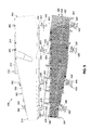
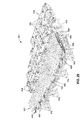
- Figure 3 is a plan view of a wing skin configured as a stiffened composite skin panel 150.
- the wing skin may extend from a root portion 116 to a tip portion 118 and may include a nacelle portion 120 at a location where the engine nacelles 112 are mounted to the wings 114.
- the wing skin may be formed of composite plies 162 which may be locally increased at certain areas along a spanwise direction 154 of the wing 114 to accommodate increased loads at such locations.
- the root portion 116 may have a generally increased laminate thickness 164 relative to the tip portion 118.
- the nacelle portion 120 may have an increased laminate thickness 164 relative to the laminate thickness 164 at the root portion 116 to accommodate increased loads from the engine nacelles 112.
- the stiffened composite skin panel 150 may be made up of a composite skin 152 and a plurality of composite stiffeners 200 which are shown oriented generally parallel to one another and extending along a spanwise direction 154 from the root portion 116 of the tip portion 118 of the wing skin.
- the composite skin 152 may be laid up on a layup surface 306 of the caul plate 302 as mentioned above.
- the composite stiffeners 200 may be separately laid up on stiffener tooling 482. After separate layup of the composite skin 152 and composite stiffeners 200, the composite skin 152 and the composite stiffeners 200 may be assembled or mated using the rotatable strongback 370 disclosed herein.
- the strongback 370 may be released or decoupled from the caul plate 302, and the strongback 370 may be rotated back to the open position leaving the caul plate docked to the stiffener tooling assembly 480.
- the layup surface 306 of the caul plate may be used as a caul surface for imparting the surface finish and outer mold line (OML) contour into the composite skin 152 during co-curing or co-bonding of the composite skin 152 to the composite stiffeners 200.
- OML outer mold line
- system 300 and method are described in the context of an integrally-stiffened composite wing skin for an aircraft 100, the system 300 and method may be implemented for forming composite structures for any vehicular or non-vehicular application, without limitation.
- the system 300 and method may be implemented for forming any type of composite structure wherein an uncured composite skin 152 is co-cured or co-bonded with cured or uncured composite stiffeners 200.
- the system 300 and method may be implemented for assembling and co-bonding a cured composite skin 152 layup with uncured composite stiffeners 200.
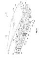
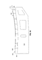
- Figure 4 is a side view of the stiffened composite skin panel 150 of Figure 3 .
- the skin panel is shown having a curved shape extending from the root portion 116 to the tip portion 118.
- the stiffened composite skin panel 150 may have a planar shape and/or a contoured curvature along any portion of the skin panel.
- the curvature may extend along one or more directions such as along a spanwise direction 154 or a chordwise direction 156.
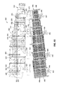
- Figure 5 is an end view of the stiffened composite skin panel 150 of Figure 3 showing a plurality of composite stiffeners 200 formed on an inner mold line 158 surface of the stiffened composite skin panel 150.
- a plurality of the composite stiffeners 200 are shown uniformly distributed along a chordwise direction 156.
- the stiffened composite skin panel 150 may include any number of composite stiffeners 200 which may be distributed uniformly or non-uniformly.
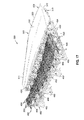
- Figure 6 is a magnified view of a portion of the stiffened composite skin panel 150 of Figure 5 comprised of a composite skin 152 and a plurality of composite stiffeners 200.
- the composite skin 152 and the composite stiffeners 200 may be formed of a plurality of composite plies 162.
- the composite plies 162 may be made up of a plurality of reinforcing fibers (not shown) surrounded by matrix material (not shown).
- the reinforcing fibers may be high-modulus or high-strength fibers formed of carbon, glass, or other fiber material.
- the fibers in a composite ply may be continuous fibers that may be commonly aligned or oriented in a single direction (e.g., unidirectional fibers), or the fibers in a composite ply may be woven together in two or more directions in a fabric arrangement (not shown).
- the composite plies 162 may be provided as pre-impregnated composite plies 162 wherein the reinforcing fibers may be pre-impregnated with a polymeric matrix material (e.g., prepreg) such as thermosetting resin (e.g., epoxy).
- the composite skin 152 may be formed as a sandwich construction having a core (not shown) sandwiched between a pair of composite laminate face sheets (not shown), and is not limited to being formed as a solid laminate of composite plies 162.
- FIG 7 is an exploded view of a portion of the stiffened composite skin panel 150 of Figure 6 illustrating a plurality of composite plies 162 that make up the composite skin 152.
- the composite stiffeners 200 are formed by side-by-side assembly of a plurality of inverted L-shaped composite elements.
- Each L-shaped composite element may include a flange 206 and a web 204 extending outwardly from the flange 206.
- the flanges 206 of a plurality of L-shaped composite elements may be assembled to the composite skin such that the flanges 206 are in contacting relation with the inner mold line 158 surface of the composite skin 152.
- the webs 204 of adjacent L-shaped composite elements may be disposed in back-to-back relation to one another to form a plurality of blade section 202 composite stiffeners 200.
- a radius filler 170 may be installed within notch formed between each adjacent pair of composite stiffeners 200.
- the composite stiffeners 200 may be formed in other cross-sectional shapes including, but not limited to, a C-section, an I-section, a hat section, or other shapes.
- Figure 8 is a perspective view of an example of a system 300 for manufacturing a stiffened composite skin panel 150.
- the system 300 is shown in an open position 400 and includes a caul plate 302 upon which the composite skin 152 may be laid up.
- the caul plate 302 may be releasably coupled to a strongback 370.
- the strongback 370 may be mounted to one or more hinges 420.
- the hinges 420 may facilitate rotation of the strongback and caul plate between an open position 400 and a closed position 402 for mating the composite skin 152 with a plurality of composite stiffeners 200 that may be individually laid up on stiffener tooling 482 to form a stiffener tooling assembly 480.
- the stiffener tooling assembly 480 may be supported on a bond cart 486 which may comprise a truss structure supported on a surface such as a shop floor.
- the system 300 may include one or more posts 452 positioned around a perimeter of the stiffener tooling assembly 480.
- One or more of the posts 452 may include a linear actuator 456 for supporting the mass the strongback 370 and for vertically lowering the caul plate 302 into docking engagement with the stiffener tooling 482, and vertically raising (e.g., undocking) the caul plate 302 off of the stiffener tooling assembly 480 after curing of the stiffened composite skin panel 150.
- FIG 9 is a top view of the system 300 of Figure 8 showing a set of four (4) hinges 420 attached to the strongback 370.
- Each one of the hinges 420 may include a fixed hinge portion 430 having a hinge base 422 that may be fixedly mounted to a fixed object 424 such as a shop floor or other non-movable surface or object.
- each one of the hinges 420 may include a movable hinge portion 440 coupled to a fixed hinge portion 430 by a hinge pin 426 defining a hinge axis 428.
- the hinge axes 428 of the hinges 420 may be aligned with one another (e.g., collinear).
- Figure 10 is a bottom view of the system 300 of Figure 8 .
- the hinge base 422 may include one or more legs extending laterally outwardly from the fixed hinge portion 430 to support the mass of the strongback 370 during rotation between the open position 400 and the closed position 402.
- Also shown in Figure 10 are one or more indexing mechanisms 320 that may be incorporated into the strongback 370 and caul plate 302.
- an indexing mechanism 320 may comprise a discrete engagement point or attachment point between the caul plate 302 and the strongback 370.
- the indexing mechanisms 320 may be distributed along a spanwise direction 154 and/or a chordwise direction 156 of the strongback 370 for indexing or aligning the strongback 370 with the caul plate 302.
- the indexing mechanisms 320 may function as load-bearing points for uniformly supporting the mass of the caul plate 302 on the strongback 370 in the open position 400 such as during layup of composite plies 162 to form a composite skin 152.
- Figure 11 is an exploded view of the caul plate 302 and the strongback 370.
- the caul plate 302 may be constructed as a relatively lightweight structure.
- the strongback 370 may be constructed as a relatively stiff frame or truss structure 372 configured to support the caul plate 302 during layup of the composite skin 152 and during rotation of the caul plate 302 between the open position 400 and closed position 402.
- the system 300 may incorporate one or more indexing mechanisms 320 for releasably coupling the strongback 370 to caul plate 302.
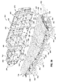
- FIG 12 is a perspective view of the caul plate 302 showing the backside 304.
- the caul plate 302 may be formed as a grid or framework 308 of interconnected ribs 310 and/or bulkheads 312 extending along a chordwise direction 156 and/or a spanwise direction 154.
- the framework 308 of ribs 310 and bulkheads 312 may form a backing structure to support a face sheet defining the layup surface 306 of the caul plate 302.
- the ribs 310 and/or the bulkheads 312 be formed as composite ribs 310 and/or composite bulkheads 312.
- caul plate 302 may significantly reduce the structural mass and thermal mass of the caul plate 302.
- any portion of the caul plate 302 may be formed of metallic material, or a combination of metallic material and composite material.
- the caul plate 302 when the caul plate 302 is attached to the strongback 370, the caul plate 302 may be globally stiff (e.g., along the spanwise direction 154 and/or along the chordwise direction 156) to maintain the intended contour of the outer mold line 160 of the layup surface 306 of the caul plate 302.
- the caul plate 302 when detached from the strongback 370, the caul plate 302 may be locally compliant in an out-of-plane direction to accommodate spanwise differential changes in laminate thickness 164 during debulking of the composite skin 152 and/or during co-curing or co-bonding of the composite skin 152 to the composite stiffeners 200.
- FIG 13 is a perspective view of an example a socket fixture 328 of an indexing mechanism 320 for indexing or aligning the strongback 370 with the caul plate 302.
- the socket fixture 328 may include a socket plate 330 having a socket 332 or bore.
- the socket plate 330 may be mechanically fastened and/or adhesively bonded to the caul plate 302 such as to one or more of the vertically oriented ribs 310 and/or bulkheads 312 of the caul plate 302.
- the socket plate 330 may be mounted to the backside 304 of the caul plate 302.
- Figure 14 is a perspective view of an example of a ball fixture 322 mounted to the strongback 370.
- the ball fixture 322 includes a plate 324 having a ball 326 protruding above the plate.
- the ball 326 may be sized and configured to engage a socket 332 of a socket fixture 328 which may be mounted on the caul plate 302.
- a plurality of ball fixtures 322 and socket fixtures 328 may be respectively mounted on the strongback 370 and caul plate 302, or vice versa.
- the plurality of ball fixtures 322 and socket fixtures 328 may be distributed over the spanwise direction 154 and chordwise direction 156 of the strongback 370 and caul plate 302 and may guide the caul plate 302 and strongback 370 into engagement with one another.
- Figure 15 is a perspective view of an example of a ball fixture 322 incorporating a clamp 334 for clamping the caul plate 302 to the strongback 370.
- the socket fixtures 328 may include a clamp 334 for releasably coupling the strongback 370 to the caul plate 302.
- the clamps 334 may be uniformly distributed along the strongback 370 for uniformly supporting the mass of the caul plate 302 when the caul plate 302 is suspended from or supported by the strongback 370 such as during rotation of the strongback and caul plate into the closed position 402 or hover position 404 ( Figure 37 ).
- FIG 16 is a perspective view of the caul plate 302 clamped to the strongback 370.
- One or more of the clamps 334 may be integrated into one or more of the socket fixture 328 and/or ball fixtures 322.
- Each clamp may include a clamp arm 336 configured to engage an underside of the plate 324, 330 of the respective ball fixture 322 and/or socket fixture 328.
- the clamp arm 336 may be pneumatically actuated although other means may be implemented for actuating the clamps 334 including, but not limited to, hydraulic actuation, electromechanical actuation, or other means.
- Figure 17 is a perspective view of the caul plate 302 and the stiffener tooling assembly 480 in the open position 400.
- the caul plate 302 is shown supporting a composite skin 152.
- the composite stiffeners 200 may be separately laid up on stiffener tooling 482 such as when the stiffener tooling assembly 480 is in the open position 400.
- Figure 18 is a sectional view of an example of caul plate 302 supported on a strongback 370.
- the composite skin 152 may be formed by laying up a plurality of composite plies 162 in a predetermined ply stacking sequence (not shown) on the layup surface 306 of the caul plate 302.
- the strongback 370 may provide a stiff supporting structure to prevent deformation of the contour of the layup surface 306 during the layup process.
- FIG 19 is a sectional view of an example of a stiffener tooling assembly 480 supported on a bond cart 486 (diagrammatically represented).
- the stiffener tooling 482 may comprise a plurality of stiffener form blocks 484.
- uncured composite plies 162 may be laid up on individual stiffener form blocks 484 to form one or more L-shaped composite elements as shown in Figure 7 .
- each one of the stiffener form blocks 484 may be configured to form a pair of L-shaped composite elements each having a web 204 and a flange 206.
- the stiffener form blocks 484 may be assembled in parallel, side-by-side arrangement such that the webs 204 of adjacent L-shaped composite elements are in contact with one another.
- the flanges 206 of the composite stiffeners 200 may collectively form a contour that matches the contour of the inner mold line 158 of the composite skin 152 to be mated to the flanges 206.
- the composite stiffeners are shown as blade sections 202 formed as back-to-back L-shaped composite elements, the composite stiffeners 200 may be provided in any one of a variety of different cross-sectional configurations (e.g., hat section, C-section, I-section, etc.) By assembling any one of a different variety of configurations of composite elements.
- FIG 20 is an end view of the caul plate 302 supported on the strongback 370 which is coupled to a hinge 420.
- One side of the strongback 370 may be supported by one or more hinges 420.
- An opposite side of the strongback 370 may be supported by one or more jack stands 382 or other support structure supporting the strongback support fittings 380.
- each hinge 420 may have a hinge base 422, a fixed hinge portion 430, and a movable hinge portion 440.
- the fixed hinge portion 430 may extend upwardly from the hinge base 422.
- the fixed hinge portion 430 may include one or more vertically oriented fixed hinge plates 432. In one example, each one of the fixed hinge plates 432 may support a hinge pin 426.
- the movable hinge portion 440 may include one or more movable hinge plates 442.
- the hinge 420 may further include at least one hinge pin 426 coupling the fixed hinge plates 432 coupled to the movable hinge plates 442 by one or more of the hinge pins 426.
- each hinge 420 may include a pair of parallel fixed hinge plates 432 extending vertically upwardly from the hinge base 422.
- each fixed hinge plate 432 may have an opposing pairs of movable hinge plates 442 positioned on opposite sides of the fixed hinge plate 432 and coupled to A hinge pin 426 extending through the fixed hinge plate 432.
- a hinge 420 may be provided in any configuration that provides a fixed hinge portion 430 and a movable hinge portion 440 for rotating the strongback 370.
- Figure 21 is a sectional view of an example of a hinge 420 with some of the hinge plates 432, 442 removed to illustrate the actuators 434, 436, 438, 456.
- the strongback 370 may be coupled to one or more of the movable hinge plates 442 using a strongback attach fitting 376.
- the strongback attach fitting 376 may include one or more mating grooves or slots 378 which may be sized and configured to engage one or more strongback mounting pins 444 that may be fixedly included with the movable hinge plates 442.
- the strongback attach fitting 376 may include a pair of hooks which may have slots 378 to allow for releasable coupling of the strongback 370 to the fixed hinge plates 432 such as by vertically raising or lowering the strongback 370 to respectively disengage or engage the slots 378 with the strongback mounting pins 444.
- the hinge 420 may include one or more mechanical stops 458 to prevent sliding motion of the strongback attach fitting 376 relative to the strongback mounting pins 444.
- a mechanical stop 458 may be configured as a lever 462 that may be rotatably mounted to one or more of the movable hinge plates 442.
- the lever 462 may have a terminal end that may be rotated into a locked position such that the terminal end bears against at least one of the hooks to prevent movement of the strongback attach fitting 376 relative to the strongback mounting pins 444.
- the hinge 420 may include a pair of rotational actuators 434 for rotating the movable hinge portion 440 and the strongback 370 and caul plate 302 that may be coupled to the strongback 370.
- the hinge 420 may also include a linear actuator 456 for controlling gravity-induced vertical movement of the caul plate 302 and strongback 370 after the lever 462 is rotated into an unlocked position such that the terminal end of the lever 462 is no longer contacting the strongback attach fitting 376.
- the linear actuator 456 may allow for gravity-induced vertical motion of the strongback 370 caul plate 302 from a hover position 404 ( Figure 39 ) above the stiffener tooling assembly 480 to a docked position 406 ( Figure 40 ).
- the composite skin 152 may be in contact with the composite stiffeners 200 which may be supported on the stiffener tooling 482.
- the rotational actuators 434 and/or linear actuators 456 may be configured as hydraulic cylinders 464.
- one or more of the hinges 420 may include a pair of rotational actuators 434 such as a first rotational actuator 436 and a second rotational actuator 438.
- the rotational actuators 434 may be positioned between the fixed hinge plates 432 and the movable hinge plates 442. However, the rotational actuators 434 may be mounted on one or both exteriors sides of the hinge 420. In the example shown, a lower end of the first rotational actuator 436 and a lower end of the second rotational actuator 438 may be coupled to the hinge base 422. An upper end of the first rotational actuator 436 and an upper end of the second rotational actuator 438 may be pinned to one or more of the movable hinge plates 442 of the movable hinge portion 440.
- the lower end of the first and second rotational actuator 436, 438 may be coupled to the hinge base 422.
- the upper end of the first rotational actuator 436 may be pinned to one or more of the movable hinge plates 442 at a different location than the location where the second rotational actuator 438 is pinned to one or more of the movable hinge plates 442.
- first rotational actuator 436 and the second rotational actuator 438 may each be configured as a dual-acting hydraulic cylinders in the sense that each actuator may have the capability for alternately applying a pushing force and a pulling force to assist in rotating the strongback 370 about the hinge axis 428.
- first and second rotational actuator 436, 438 may each be extended to apply a pushing force to rotatably urge the movable hinge plates 442 upwardly.
- first and second rotational actuator 436, 438 may at different times separately start contracting and applying a pushing force to resist the contraction urged by the gravity-induced downward motion of the strongback 370.
- the first and second rotational actuator 436, 438 may be configured to maintain a substantially constant rate of rotation of the strongback 370.
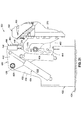
- Figure 22 is a perspective view of the system 300 showing the caul plate 302 and strongback 370 at a halfway point during the rotation from the open position 400 ( Figure 17 ) toward the closed position 402 ( Figure 22 ).
- the system 300 may include at least one alignment mechanism 350 configured to align the caul plate 302 to the stiffener tooling assembly 480 as the two components are moved into docking engagement with one another.
- an alignment mechanism 350 may comprise a computer aided metrology (CAM) device such as a vision system and/or a laser measurement device 352 configured to detect misalignment of the composite skin 152 with the composite stiffeners 200 as the composite skin 152 is moved into contact with the composite stiffeners 200 during lowering of the strongback 370 and caul plate 302 onto the stiffener tooling assembly 480.
- CAM computer aided metrology
- one or more laser measurement devices 352 may initially be indexed to the hinge axes 428 of the hinges 420.
- One or more of the laser measurement devices 352 such as a time-of-flight laser (not shown) may be mounted to surrounding structure such as a ceiling or a wall of the building or to one or more alignment fixtures (not shown) that may be erected adjacent to the stiffener tooling assembly 480 or to a floor-mounted support or stand (not shown).
- the alignment mechanism 350 is not limited to one or more laser measurement devices 352, and may include alignment devices of any suitable configuration for detecting the location of one or more optical tooling targets 354 that may be mounted at one or more locations around the perimeter of the stiffener tooling assembly 480.
- the alignment mechanism 350 may detect or measure the amount of offset or mismatch between a measured location of the optical tooling targets 354 and a desired location of the optical tooling targets 354 relative to the hinge axes 428.
- the desired location of the optical tooling targets 354 may represent a condition wherein that the caul plate 302 is aligned with the stiffener tooling assembly 480.
- the location of the optical tooling targets 354 may be defined in terms of aircraft coordinates (e.g., station, water line, butt line) or in any other suitable reference coordinate system.
- one or more laser measurement devices 352 may be activated to monitor the position of the stiffener tooling assembly 480. Based upon the offset or mismatch between the measured location and desired location of the optical tooling targets 354, the x-y position of the stiffener tooling assembly 480 may be adjusted such as by using one or more portable dollies (not shown) or automated guided vehicles (not shown) until the offset or mismatch between the measured location and the desired location of each optical tooling target 354 is within a predetermined tolerance.
- one or more of the automated guided vehicles may be positioned underneath the stiffener tooling assembly 480 and may be configured to vertically lift the stiffener tooling assembly 480 off the shop floor by an amount sufficient to allow adjustment of the x-y position of the stiffener tooling assembly 480 relative to the caul plate 302, after which the automated guided vehicles may then lower the stiffener tooling assembly 480 back into contact with the shop floor.
- Figure 23 is a perspective view of the system 300 showing the caul plate 302 and strongback 370 in the closed position 402 relative to the stiffener tooling assembly 480.
- the system 300 may include one or more posts 452 which may be positioned around the perimeter of the stiffener tooling assembly 480 such as along one or more sides of the stiffener tooling assembly 480.
- One or more of the posts 452 may include one or more linear actuators 456 for supporting the mass of the strongback 370 in the closed position 402.
- one or more of the hinges 420 may also include one or more linear actuators 456 for supporting the mass of the strongback 370 in cooperation with the linear actuators 456 of the posts 452.
- linear actuators 456 are linear in the sense that they control the linear or vertical motion of the strongback 370 from the hover position 404 to the docked position 406, and vice versa.
- the linear actuators 456 are not limited to actuators that move along a linear direction such as an actuating cylinder (e.g., a hydraulic cylinder 464), and may include alternative forms of actuators configured for moving the strongback 370 and caul plate 302 along a linear or vertical direction such as between a hover position 404 and a docked position 406.
- the linear actuators 456 are part of a counterbalancing system 450 configured to counterbalance or support at least a portion of the mass of the strongback 370 when the caul plate 302 is docked to the stiffener tooling assembly 480 to allow the composite skin 152 and the composite stiffeners 200 to be moved into contact with one another and avoid transmitting the mass the strongback 370 onto the mated components.
- the closed position 402 may be described as a position wherein the strongback 370 and the caul plate 302 are rotated into position above the stiffener assembly tooling 480 or into engagement with the stiffener tooling assembly 480.
- the closed position 402 encompasses both the hover position 404 and the docked position 406.
- the hover position 404 may be described as a position wherein the caul plate 302 and the composite stiffener 200 are in vertically spaced relation to one another.
- the docked position 406 may be described as a position wherein the caul plate 302 is engaged with the stiffener tooling assembly and/or the composite skin 152 is in contact with the composite stiffeners 200.
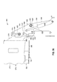
- Figure 24 is a side view of the caul plate 302 and strongback 370 in the closed position 402 (e.g., docked position 406).
- the caul plate 302 is positioned above the stiffener tooling assembly 480.
- Figure 24 illustrates a linear actuator 456 included with each one of the hinge 420 and the post 452.
- Each post 452 may be supported on the shop floor or other fixed object (not shown).
- Each linear actuator 456 may be mounted adjacent to or on a top of a post 452.
- the linear actuators 456 may extend upwardly from the posts 452 and may be configured to engage a corresponding plurality of strongback support fitting 380 that may be included with the strongback 370.
- the strongback support fittings 376 may be mounted to a strongback perimeter 374 such as along a side of the strongback 370.
- a post 452 mounted on a side of the stiffener tooling assembly 480 opposite each one of the hinges 420.
- the counterbalancing system 450 may prevent a substantial portion or an entirety of the strongback 370 mass from being transferred onto the composite skin 152 and the composite stiffeners 200 sandwiched between the caul plate 302 and the stiffener tooling 482.
- the counterbalancing system 450 may prevent the application of excessive compaction pressure on the composite layup and the composite stiffeners 200 which may otherwise compromise the integrity of the composite layups and/or may result in damage to the caul plate 302, the stiffener tooling 482, and/or the bond cart 486.
- Figure 25 is a side view of a post 452 having a linear actuator 456 for supporting at least a portion of the mass of the strongback 370 in the closed position 402 and for vertically lowering the strongback 370 from a hover position 404 to a docked position 406.
- the post 452 may also include a mechanical stop 458 as a fail-safe mechanism for supporting the strongback 370 in the event of a failure of one or more of the linear actuators 456.
- the mechanical stop 458 may be configured as a threaded rod 460 which may be threadably engaged to the post 452.
- the threaded rod 460 may include a top end configured to engage the strongback support fitting 380 to prevent the mass of the strongback 370 from being transmitted to the caul plate 302.
- Figure 26 is a side view of a hinge 442 showing the first rotational actuator 436 and second rotational actuator 438 for rotating a movable hinge portion 440 of the hinge 442. Also shown is a linear actuator 456 which may be included with the hinge for supporting and/or vertically lowering the strongback 370 from a hover position 404 to a docked position 406. In the example shown, the linear actuator 456 may be extended into engagement with the strongback attach fitting 376 to prevent vertical motion of the strongback 370 when the strongback 370 and caul plate 302 are inverted. In addition, the lever 462 may be rotated into engagement with the strongback attach fitting 376 to assist the linear actuator 456 in preventing vertical motion of the strongback 370 when inverted.
- the linear actuator 456 may optionally include a mechanical stop 458 (e.g., a threaded rod 460) and which may be configured to prevent vertical motion of the strongback 370 upon a failure of the linear actuator 456 when the lever 462 is rotated into an unlocked position (e.g., see Figure 40 )
- a mechanical stop 458 e.g., a threaded rod 460
- the linear actuator 456 may optionally include a mechanical stop 458 (e.g., a threaded rod 460) and which may be configured to prevent vertical motion of the strongback 370 upon a failure of the linear actuator 456 when the lever 462 is rotated into an unlocked position (e.g., see Figure 40 )
- Figure 27 is a schematic diagram of a strongback counterbalancing system 450 including a plurality of the linear actuators 456 for supporting the mass of the strongback 370 and vertically lowering the caul plate 302 from a hover position 404 to a docked position 406, and vice versa.
- the counterbalancing system 450 includes a hydraulic cylinder 464 (e.g., a linear actuator 456) at each one of the first, second, third, and fourth hinges 420a, 420b, 420c, 420d located on one side of the strongback 370 and a corresponding hydraulic cylinder 464 (e.g., a linear actuator 456) at each one of the first, second, third, and fourth posts 452a, 45sb, 452c, 452d positioned on an opposite side of the strongback 370 when in the closed position 402.
- a hydraulic cylinder 464 e.g., a linear actuator 456
- a linear actuator 456 e.g., a linear actuator 456
- the posts 452a, 45sb, 452c, 452d and hinges 420a, 420b, 420c, 420d may respectively form four (4) hinge-post sets including a first, second, third, and fourth hinge-post set 470a, 470b, 470c, 470d.
- the hydraulic cylinders 464 may be fluidly coupled (e.g., via hydraulic lines) and/or electrically connected (e.g., via electrical wiring - not shown) to a hydraulic pressure controller 468 which may be configured to regulate hydraulic pressure at each hydraulic cylinder 464.
- the hydraulic pressure controller 468 may regulate the hydraulic pressure at each hydraulic cylinder 464 in proportion to the local mass fraction of the strongback 370 at each hydraulic cylinder 464. For example, if the local mass fraction of the strongback 370 at the first hinge-post set 470a is analytically determined to be 25% of the total mass of the strongback 370, the hydraulic system 454 may regulate the hydraulic pressure at the hydraulic cylinder 464 at the first hinge 420a and first post 452a to support the 25% local mass fraction. The hydraulic pressure controller 468 may likewise regulate hydraulic pressure at the second, third, and fourth hinge-post sets 470b, 470c, 470d according to the local mass fraction of the strongback 370 at each one of the hinge-post sets 470b, 470c, 470d.
- the hydraulic pressure controller 468 may be configured to vertically lower the caul plate 302 from a hover position 404 ( Figure 39 ) to a docked position 406 ( Figure 40 ) while the alignment mechanism 350 monitors mismatch between a current location of the optical tooling targets 354 and a desired location of the optical tooling targets 354, as described above.
- the location of the stiffener tooling assembly 480 may be adjusted using one or more dollies or automated guided vehicles (not shown) until the caul plate 302 is aligned with the stiffener tooling assembly 480 and prior to contact between the composite skin 152 and the composite stiffeners 200.
- Figure 28 is a perspective view of the system 300 showing the rotation of the strongback 370 toward the open position 400 after the caul plate 302 has been docked to the stiffener tooling assembly 480 and the strongback 370 has been decoupled from the caul plate 302.
- decoupling the caul plate 302 from the strongback 370 may be effectuated by releasing the clamp arms 336 coupling the strongback 370 to the caul plate 302 as shown in Figures 15-16 .
- Figure 29 is a perspective view of the strongback 370 in the open position 400.
- the strongback 370 may be supported by the hinges 420 on one side of the caul plate 302 and by one or more jack stands 382 ( Figure 20 ) on an opposite side of the caul plate 302.
- the caul plate 302 is shown docked to the stiffener tooling assembly 480 sandwiching the composite skin 152 and composite stiffeners 200 between the caul plate 302 layup surface 306 and the stiffener tooling 482.
- Figure 30 is a perspective view of the caul plate 302 docked to the stiffener tooling assembly 480 with the strongback 370 removed.
- the composite skin 152 and the composite stiffeners 200 are mated together to form a composite assembly.
- a vacuum bag assembly (not shown) may be applied to the composite assembly in preparation for debulking, and/or co-curing or co-bonding.
- the composite stiffeners 200 and the composite skin 152 may be sealed to the caul plate 302 with a bagging film (not shown). The edges of the bagging film may be sealed to the backside 304 of the caul plate 302.
- the composite assembly included the caul plate 302, the stiffener tooling assembly 480, and the bond cart 486 may be transferred to an oven or autoclave by engaging (e.g., lifting) the bond cart 486 with one or more dollies.
- Compaction pressure may be applied by drawing 114 a vacuum on the bagging film and/or applying autoclave pressure (not shown) during debulking and/or co-curing and/or co-bonding the composite skin 152 to the composite stiffeners 200.
- Figure 31 is a diagrammatic exploded sectional view of the composite assembly taken along a spanwise direction 154 and illustrating an exaggerated pre-debulk thickness 166 of a composite skin 152 varying along the spanwise direction 154. Also shown is a flange 206 of a composite stiffener 200 that may be contoured complementary to the composite skin 152.
- the composite skin 152 has a laminate thickness 164 that is greater at a root portion 116 than at the tip portion 118 of the composite skin 152.
- the composite skin 152 may include a nacelle portion 120 within which the laminate thickness 164 may be locally increased to support the increased load from the engine nacelles 112 supported by the wing 114 at that location.
- a wing skin may include approximately 30 composite plies 162 at the tip portion, approximately 130 composite plies 162 at the root portion 116, and a local buildup of up to approximately 150 composite plies 162 or more at the nacelle portion 120.
- the spanwise variation in laminate thickness 164 may result in variations in the amount by which the laminate thickness 164 is reduced during debulking, as described in greater detail below.
- Figure 32 is a diagrammatic view of the composite skin 152 and composite stiffeners 200 sandwiched between the stiffener tooling 482 and the caul plate 302 for applying compaction pressure to the composite skin 152 and composite stiffeners 200 for debulking.
- compaction pressure may be applied by drawing 114 a vacuum on a bagging film sealing the composite assembly to the caul plate 302. Additional compaction pressure may be applied in an autoclave environment. In this regard, a compaction pressure of several atmospheres or more may be applied by the caul plate 302 onto the composite skin 152 and composite stiffeners 200 supported by the stiffener tooling 482.
- Figure 33 is a diagrammatic view of the assembly of Figure 32 showing the compliance (e.g., out-of-plane flexibility) of the caul plate 302 with the strongback 370 detached from the caul plate.
- the laminate thickness 164 may be reduced by approximately 10%.
- the caul plate 302 may advantageously be configured to be locally compliant to allow for out-of-plane flexing to accommodate the different amounts by which the laminate thickness 164 may reduce from a pre-debulk thickness 166 to a post-debulk thickness 168 during the debulking process.
- the caul plate 302 may be locally compliant to accommodate a reduction in laminate thickness 164 as a result of cure shrinkage that may occur during the curing of thermosetting composite plies 162.
- Figure 34 is a perspective view of the system 300 after co-curing or co-bonding the composite assembly to form a stiffened composite skin panel 150.
- the caul plate 302 may be attached to the strongback 370 and vertically raised from the docked position 406 to the hover position 404 and then rotated from the closed position 402 to the open position 400.
- the cured stiffened composite skin panel 150 may be removed from the stiffener tooling 482 for post-processing such as inspection.
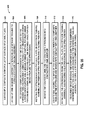
- Figure 35 is a flowchart containing one or more operations that may be included in a method 500 of manufacturing a stiffened composite skin panel 150.
- the method may include Step 502 of providing a caul plate 302 including a layup surface 306 for supporting a composite skin 152.
- the method may further include laying up a plurality of composite plies 162 to form an composite skin 152 on the layup surface 306 as shown in Figure 36 .
- the composite skin 152 may be formed of uncured composite plies 162 which may then be assembled with cured or uncured composite stiffeners using the detachable strongback 370 disclosed herein as shown in Figure 36 .
- the method may include using the strongback 370 and caul plate 302 to rotate a cured composite skin 152 onto cured or uncured composite stiffeners 200 for co-curing or co-bonding.
- Step 504 of the method may include providing a stiffener tooling assembly 480 ( Figure 36 ) having one or more composite stiffeners 200 laid up on stiffener tooling 482.
- the method may include laying up a plurality of composite plies 162 to form one or more uncured composite stiffeners 200 on the stiffener tooling 482.
- the stiffener tooling 482 may comprise a plurality of stiffener form blocks 484 each having a layup of composite plies 162.
- the stiffener form blocks 484 containing the uncured composite plies 162 may be arranged side-by-side to form a stiffener tooling assembly 480.
- Step 506 of the method may include releasably coupling a strongback 370 to the caul plate 302 for supporting the caul plate 302 during layup of a composite skin 152 and during rotation ( Figure 37-38 ) of the caul plate 302 onto a stationary stiffener tooling assembly 480 using a plurality of hinges 420 as described above.
- the method instead of coupling the strongback 370 to the caul plate 302 for rotation into engagement with a stationary stiffener tooling assembly 480, the method may comprise coupling the strongback 370 to the stiffener tooling assembly 480 prior to rotation of the strongback-stiffener tooling assembly 480 into engagement with a stationary caul plate 302.
- the method is presently described in the context of rotating the strongback 370 and caul plate 302 onto a stationary stiffener tooling assembly 480, although the structural components and the operational steps are substantially similar for each option.
- the method may include releasably clamping the strongback 370 to the caul plate 302 or to the stiffener tooling assembly 480 ( Figure 36 ).
- the method may include actuating one or more clamps 334 mounted to the strongback 370 for clamping the backside 304 of the caul plate 302 to the strongback 370 as shown in Figures 9-16 .
- the clamps 334 ( Figures 15-16 ) may include clamp arms 336 which may be pneumatically actuated and/or hydraulically actuated.
- the clamps 334 may include pneumatic cylinders for actuating the clamp arms 336 to clamp a socket fixture 328 of the caul plate 302 to a ball fixture 322 of the strongback 370.
- the strongback 370 may be coupled to the caul plate 302 prior to the layup of the composite skin 152 and prior to rotation of the caul plate 302 into engagement with the stiffener tooling assembly 480.
- the method may additionally include indexing, using at least one indexing and the mechanism 320 (e.g. Figures 13-14 ), the strongback 370 with the caul plate 302 or the stiffener tooling assembly 480.
- the caul plate 302 may include a plurality of socket fixtures 328 ( Figure 13 ) for engagement with a corresponding quantity of ball fixtures 322 ( Figure 14 ).
- the method may include engaging a ball fixture 322 to a socket fixture 328 respectively mounted to the strongback 370 and the caul plate 302, or vice versa.
- each one of the socket fixtures 328 may include a plate 330 having a socket 332 sized and configured to receive a ball 326.
- At least one of the ball fixtures 322 and/or socket fixtures 328 including a clamping mechanism such as a clamp 334 for releasably clamping the caul plate 302 to the strongback 370.
- Step 508 of the method may include rotating the strongback 370 between an open position 400 ( Figure 36 ) and a closed position 402 ( Figure 38 ).
- Figure 36 is an end view of the strongback 370 and caul plate 302 and the stiffener tooling assembly 480 in the open position 400.
- Figure 37 shows the strongback 370 and caul plate oriented approximately vertically during an approximate halfway point during rotation from the open position 400 to the closed position 402 relative to the stiffener tooling assembly 480.
- the composite skin 152 may be retained against the layup surface 306 of the caul plate 302 by molecular adhesion and/or by mechanical means.
- Figure 38 shows the caul plate 302 and the strongback 370 in the closed position 402. As indicated above, the closed position may encompass a hover position 404 of the caul plate 302 above the stiffener tooling assembly 480.
- Figure 39 shows the caul plate 302 and strongback 370 in the hover position 404 and a gap 408 between the composite skin 152 and the composite stiffeners 200.
- the hover position 404 at least a portion of the mass of the strongback 370 may be supported by one or more linear actuators 456 that may be included with one or more hinges 420 and/or one or more posts 452.
- the rotation of the strongback 370 may be facilitated by one or more rotational actuators 434 ( Figure 26 ) that may be included with one or more hinges 420 to which the strongback 370 may be coupled as described above.
- the step of rotating the strongback 370 and caul plate 302 may include actuating a first rotational actuator 436 ( Figure 26 ) and a second rotational actuator 438 ( Figure 26 ) that may be included with each one of the hinges 420 supporting the strongback 370.
- Step 510 of the method may include moving the composite skin 152 and the composite stiffeners 200 into contact with one another after the caul plate 302 and the stiffener tooling assembly 480 are rotated into the hover position 404.
- the rotational actuators 434 may be actuated for initial rotation of the strongback 370 and caul plate 302 from the open position 400 to the closed position 402 which may be a hover position 404 located up to several inches or more above the stiffener tooling assembly 480.
- a gap 408 may exist between the composite skin 152 and the composite stiffeners 200 as shown in Figure 39 .
- the mechanical stop 458 or lever 462 that may be included with each hinge 420 may be rotated from a locked position ( Figure 39 ) to an unlocked position ( Figure 40 ) to permit gravity-induced vertical motion of the strongback attach fitting 376 relative to the strongback mounting pins 444 under the control of the linear actuators 456 (hydraulic cylinders 464) to remove the gap 408 between the composite skin 152 and the composite stiffeners 200.
- any mechanical stops 458 that may be included with the hinges 420 and/or posts 452 may be adjusted to allow for the linear actuators 456 to permit gravity-induced vertical motion of the strongback 370 and caul plate 302 from the hover position 404 to the docked position 406 until the gap 408 is removed and the composite skin 152 is moved into contact with the composite stiffeners 200.
- the mechanical stops 458 that may be included with the hinges 420 and/or posts 452 may be adjusted to a position such that in the event of failure of one or more of the linear actuators 456 (hydraulic cylinders 464) of the hinges 420 and/or posts 452, the mechanical stops 458 may support the mass of the strongback 370 against further vertical motion and thereby prevent the weight of the strongback 370 from being transferred to the caul plate 302 or stiffener tooling assembly 480.
- the process of docking the caul plate 302 to the stiffener tooling assembly 480 may also include aligning, using at least one alignment mechanism 350 ( Figures 22-23 ), the caul plate 302 with the stiffener tooling assembly 480.
- the step of aligning the caul plate 302 with the stiffener tooling assembly 480 may include detecting, using a computer aided metrology (CAM) device (e.g., a laser measurement device 352 - Figures 22-23 ), misalignment of the composite skin 152 with the composite stiffeners 200 based on the location of the hinge axes 428 as a reference point for the alignment mechanism 350, as described above.
- the method may further include adjusting the x-y position of the stiffener tooling assembly 480 relative to the caul plate 302 until the composite skin 152 is aligned with the composite stiffeners 200.
- adjustment of the x-y position of the stiffener tooling assembly 480 may be facilitated by using one or more dollies (not shown) or remotely guided vehicles (not shown) which may be positioned underneath the bond cart 486.
- such automated guided vehicles may lift the bond cart 486 a slight amount (e.g., up to several inches) in the vertical or z-direction to allow for positioning of the stiffener tooling assembly 480 in the x-y direction until the composite skin 152 is aligned with the composite stiffeners 200 based upon offset measurements from the alignment mechanism 350.
- the automated guided vehicles may be commanded to vertically lower the bond cart 486 back down onto the shop floor.
- Step 512 of the method may include counterbalancing, using a counterbalancing system 450, at least a portion of the mass of the strongback 370 as the composite skin 152 and the composite stiffeners 200 are moved into contact with one another, as mentioned above.
- the method may include vertically lowering the strongback 370 and the caul plate 302 from the hover position 404 to the docked position 406 until the composite skin 152 and composite stiffeners 200 are in contact with one another.
- the process of vertically lowering the strongback 370 may include supporting and lowering the strongback 370 the above-described linear actuators 456 positioned along a perimeter of the strongback 370.
- each one of the hinges 420 may include a linear actuator 456 (e.g., hydraulic cylinders 464).
- each one of the posts 452 may include a linear actuator 456.
- the linear actuators 456 may be part of the hydraulic system 454 ( Figure 27 ) and may be independently operated in cooperation with one another to support the mass of the strongback 370 and lower the strongback 370 and caul plate 302 into docking engagement with the stiffener tooling assembly 480.
- the linear actuators 456 of the counterbalancing system 450 may advantageously prevent a substantial portion of the mass of the strongback 370 or an entirety of the mass of the strongback 370 from being transferred to the caul plate 302, the composite skin 152, the composite stiffeners 200, and/or the stiffener tooling 482.
- the step of counterbalancing the mass of the strongback 370 may include regulating, using a hydraulic pressure controller 468, the hydraulic pressure at the hydraulic cylinders 464 (linear actuators 456) during the vertical positioning of the strongback 370.
- the hydraulic cylinders 464 may be fluidly coupled to and/or controlled by a hydraulic pressure controller 468.
- the hydraulic pressure controller 468 may regulate hydraulic pressure at each hydraulic cylinder 464 such that the hydraulic pressure at each hydraulic cylinder 464 is apportioned according to the local mass fraction of the strongback 370 at each hydraulic cylinder 464.
- Step 514 of the method may include detaching (e.g., unclamping) the strongback 370 from the caul plate 302 and rotating the strongback 370 to the open position 400, as shown in Figure 41-42 .
- the method may further include vacuum bagging (not shown) the composite assembly (e.g., the composite skin 152 and composite stiffeners 200) by sealing the composite assembly to the caul plate 302 using a bagging film (not shown) sealed to the caul plate 302 perimeter 314.
- Vacuum pressure (not shown) may be applied to the bagging film to apply at least one or more atmospheres of compaction pressure (e.g., autoclave pressure) onto the composite skin 152 and composite stiffeners 200 which are supported by the stiffener tooling 482.
- Step 516 of the method may include co-curing or co-bonding the composite skin 152 to the composite stiffeners 200 with the caul plate 302 engaged to the stiffener tooling assembly 480 and the strongback 370 detached from the caul plate 302.
- one or more dollies or automated guided vehicles may transport the assembly (e.g., the bond cart, the stiffener tooling 482, the composite stiffeners 200, the composite skin 152, and the caul plate 302) to an oven or autoclave for debulking and/or co-curing and/or co-bonding the composite skin 152 to the composite stiffeners 200.
- the assembly may be removed from the oven (not shown) or autoclave (not shown) such as by using the automated guided vehicles (not shown) and which may position the assembly adjacent to the strongback in the open position.
- the alignment system 350 may be activated for aligning the stiffener tooling assembly with the hinge axes 428 of the hinges 420 to which the caul plate 370 is attached.
- the rotational actuators 434 e.g., the first and second rotational actuators 436, 438) may be activated to rotate the strongback 370 ( Figure 21 ) from the open position 400 to the hover position 404.
- the linear actuators 456 at the hinges 420 and posts 452 may be regulated be the hydraulic system 454 to support the mass of the strongback 370 while vertically lowering the strongback 370 into engagement with the caul plate 302.
- the indexing mechanisms 320 may facilitate the alignment of the strongback with the caul plate such as by using the above-mentioned ball fixtures 322 and corresponding socket fixtures 328.
- the strongback 370 Once the strongback 370 is engaged to the caul plate 302, one or more of the clamp arms 336 ( Figures 15-16 ) may be actuated to clamp the caul plate 302 to the strongback 370.
- the assembly After clamping the caul plate 302 to the strongback 370, the assembly may be vertically raised to the hover position 404 such as by using the linear actuators 456.
- the rotational actuators 434 of the hinges may then be activated then to rotate the strongback 370 and caul plate 302 into the open position 400, leaving the cured stiffened composite skin panel 150 supported on the stiffener tooling 482 for post-processing such as inspection.
Landscapes
- Engineering & Computer Science (AREA)
- Mechanical Engineering (AREA)
- Architecture (AREA)
- Civil Engineering (AREA)
- Structural Engineering (AREA)
- Manufacturing & Machinery (AREA)
- Transportation (AREA)
- Aviation & Aerospace Engineering (AREA)
- Moulding By Coating Moulds (AREA)
- Casting Or Compression Moulding Of Plastics Or The Like (AREA)
Applications Claiming Priority (1)
| Application Number | Priority Date | Filing Date | Title |
|---|---|---|---|
| US14/746,844 US10035300B2 (en) | 2015-06-23 | 2015-06-23 | System and method for manufacturing a stiffened composite structure |
Publications (2)
| Publication Number | Publication Date |
|---|---|
| EP3112145A1 true EP3112145A1 (de) | 2017-01-04 |
| EP3112145B1 EP3112145B1 (de) | 2018-01-17 |
Family
ID=56148258
Family Applications (1)
| Application Number | Title | Priority Date | Filing Date |
|---|---|---|---|
| EP16175420.5A Active EP3112145B1 (de) | 2015-06-23 | 2016-06-21 | System und verfahren zur herstellung einer versteiften verbundstruktur |
Country Status (4)
| Country | Link |
|---|---|
| US (1) | US10035300B2 (de) |
| EP (1) | EP3112145B1 (de) |
| JP (1) | JP6811035B2 (de) |
| CN (1) | CN107697316B (de) |
Cited By (4)
| Publication number | Priority date | Publication date | Assignee | Title |
|---|---|---|---|---|
| CN107054686A (zh) * | 2017-04-26 | 2017-08-18 | 浙江大学 | 一种飞机翼盒前缘工艺接头定位工装 |
| GB2599169A (en) * | 2020-09-29 | 2022-03-30 | Airbus Operations Ltd | A rigid temporary reinforcement structure |
| EP4011606A3 (de) * | 2020-11-18 | 2022-10-05 | The Boeing Company | Pressblechsystem für die herstellung von flugzeugen |
| US11897210B2 (en) | 2020-11-18 | 2024-02-13 | The Boeing Company | Caul plate system for aircraft fabrication |
Families Citing this family (10)
| Publication number | Priority date | Publication date | Assignee | Title |
|---|---|---|---|---|
| TR201809686T4 (tr) * | 2014-11-27 | 2018-07-23 | Lm Wind Power Int Tech Ii Aps | Bir rüzgar türbini kanat kısmının imalatına yönelik bir ilk kalıp kısmının ikinci bir kalıp kısmına göre çevrilmesine yönelik bir çevirme aygıtı. |
| EP3118604B1 (de) * | 2015-07-14 | 2019-03-27 | Airbus Defence and Space GmbH | Prüfeinrichtung zum kontrollieren einer bauteilherstellung |
| GB201522327D0 (en) * | 2015-12-17 | 2016-02-03 | Airbus Operations Ltd | Wing structure |
| US11022094B2 (en) * | 2017-05-24 | 2021-06-01 | General Electric Company | Modular blade structure and method of assembly |
| US10730250B2 (en) * | 2018-10-05 | 2020-08-04 | The Boeing Company | Caul plates and related methods |
| CN109484672B (zh) * | 2018-11-30 | 2024-01-16 | 中国商用飞机有限责任公司北京民用飞机技术研究中心 | 一种上墙端与壁板连接整体角盒组件 |
| US11701801B2 (en) * | 2019-03-04 | 2023-07-18 | The Boeing Company | Caul plate with feature for separating from composite part |
| US11161592B2 (en) * | 2019-09-11 | 2021-11-02 | Textron Innovations Inc. | Torque box sleeves for aircraft wing assemblies |
| US11673692B2 (en) * | 2019-12-13 | 2023-06-13 | The Boeing Company | Forming tool and methods for forming a curvature into a composite stiffener |
| CN112793173B (zh) * | 2020-12-24 | 2022-09-20 | 中国航空制造技术研究院 | 一种胶接-装配一体化复合材料组件工装及装配方法 |
Citations (3)
| Publication number | Priority date | Publication date | Assignee | Title |
|---|---|---|---|---|
| WO2004043679A1 (en) * | 2002-11-12 | 2004-05-27 | Lm Glasfiber A/S | Mould assembly with closure mechanism |
| WO2008020158A2 (en) * | 2006-08-14 | 2008-02-21 | Airbus Uk Limited | Moulding tool and method of manufacturing a part bonding for example spars on a skin |
| EP2380720A1 (de) * | 2010-04-22 | 2011-10-26 | Vestas Wind Systems A/S | Verbesserte Anordnung zur Herstellung einer Windturbinenschaufel |
Family Cites Families (11)
| Publication number | Priority date | Publication date | Assignee | Title |
|---|---|---|---|---|
| US5087187A (en) * | 1990-03-09 | 1992-02-11 | United Technologies Corporation | Apparatus for molding hollow composite articles having internal reinforcement structures |
| US5538589A (en) * | 1994-08-31 | 1996-07-23 | The Boeing Company | Composite stringer assembly machine |
| FR2863198B1 (fr) | 2003-12-04 | 2006-03-03 | Airbus France | Panneaux auto-raidis en composite pre-impregne et procedes de mise en place des elements de tels panneaux |
| FR2863197B1 (fr) | 2003-12-04 | 2006-03-03 | Airbus France | Procede de mise en place des elements d'un panneau auto-raidi en composite preimpregne |
| US9199301B2 (en) * | 2010-08-11 | 2015-12-01 | Vestas Wind Systems A/S | Apparatus for fabricating a wind turbine blade and related method |
| DK2736692T3 (en) * | 2011-07-28 | 2017-01-30 | Vestas Wind Sys As | Production plant comprising a transport system for processing extended products, especially wind turbine blades, with extended mold assemblies |
| JP5854430B2 (ja) * | 2012-03-29 | 2016-02-09 | 東レ株式会社 | Frp製造装置およびfrp製造方法 |
| US8973871B2 (en) * | 2013-01-26 | 2015-03-10 | The Boeing Company | Box structures for carrying loads and methods of making the same |
| US9409348B2 (en) | 2013-02-04 | 2016-08-09 | The Boeing Company | Fabrication of stiffened composite panels |
| US20150217850A1 (en) * | 2014-02-06 | 2015-08-06 | The Boeing Company | Laminated i-blade stringer |
| TR201809686T4 (tr) * | 2014-11-27 | 2018-07-23 | Lm Wind Power Int Tech Ii Aps | Bir rüzgar türbini kanat kısmının imalatına yönelik bir ilk kalıp kısmının ikinci bir kalıp kısmına göre çevrilmesine yönelik bir çevirme aygıtı. |
-
2015
- 2015-06-23 US US14/746,844 patent/US10035300B2/en active Active
-
2016
- 2016-06-15 JP JP2016119190A patent/JP6811035B2/ja active Active
- 2016-06-21 EP EP16175420.5A patent/EP3112145B1/de active Active
- 2016-06-23 CN CN201610463455.6A patent/CN107697316B/zh active Active
Patent Citations (3)
| Publication number | Priority date | Publication date | Assignee | Title |
|---|---|---|---|---|
| WO2004043679A1 (en) * | 2002-11-12 | 2004-05-27 | Lm Glasfiber A/S | Mould assembly with closure mechanism |
| WO2008020158A2 (en) * | 2006-08-14 | 2008-02-21 | Airbus Uk Limited | Moulding tool and method of manufacturing a part bonding for example spars on a skin |
| EP2380720A1 (de) * | 2010-04-22 | 2011-10-26 | Vestas Wind Systems A/S | Verbesserte Anordnung zur Herstellung einer Windturbinenschaufel |
Cited By (5)
| Publication number | Priority date | Publication date | Assignee | Title |
|---|---|---|---|---|
| CN107054686A (zh) * | 2017-04-26 | 2017-08-18 | 浙江大学 | 一种飞机翼盒前缘工艺接头定位工装 |
| CN107054686B (zh) * | 2017-04-26 | 2019-03-19 | 浙江大学 | 一种飞机翼盒前缘工艺接头定位工装 |
| GB2599169A (en) * | 2020-09-29 | 2022-03-30 | Airbus Operations Ltd | A rigid temporary reinforcement structure |
| EP4011606A3 (de) * | 2020-11-18 | 2022-10-05 | The Boeing Company | Pressblechsystem für die herstellung von flugzeugen |
| US11897210B2 (en) | 2020-11-18 | 2024-02-13 | The Boeing Company | Caul plate system for aircraft fabrication |
Also Published As
| Publication number | Publication date |
|---|---|
| US20160375631A1 (en) | 2016-12-29 |
| EP3112145B1 (de) | 2018-01-17 |
| US10035300B2 (en) | 2018-07-31 |
| JP6811035B2 (ja) | 2021-01-13 |
| CN107697316B (zh) | 2020-12-11 |
| JP2017061134A (ja) | 2017-03-30 |
| CN107697316A (zh) | 2018-02-16 |
Similar Documents
| Publication | Publication Date | Title |
|---|---|---|
| EP3112145B1 (de) | System und verfahren zur herstellung einer versteiften verbundstruktur | |
| EP2014448B1 (de) | Verfahren und Vorrichtung zur Konturierung von vorimpregnierten Verbundteile | |
| JP6859023B2 (ja) | 複合構造を自動的にレイアップするための装置及び方法 | |
| US9017510B2 (en) | Method and apparatus for fabricating large scale integrated airfoils | |
| US10442153B2 (en) | Stiffened stringer panel with integral indexing laminate stacks | |
| US11565460B2 (en) | Systems and methods for in situ manufacturing of minimally tooled stringers | |
| US11873093B2 (en) | Composite plank support for stringer panel | |
| EP3536490A1 (de) | Umformpressen und verfahren zur herstellung von geschüttelten, versteiften verbundstrukturen | |
| EP3434459A1 (de) | Zwischenlageplatte mit kompensationsoberfläche | |
| EP3501804A1 (de) | Versteifte längsträgerplatte mit integrierten indexierungslaminatstapeln | |
| EP2989001B1 (de) | Herstellungsverfahren und tragflächenprofil mit einer torsionskastenartigen hautverbundstruktur | |
| EP3023234B1 (de) | Herstellung von versteiften Verbundplatten | |
| EP3744627A1 (de) | Stringerlose-sandwich-rumpfplatten | |
| EP3597414A1 (de) | Vorrichtungen und verfahren zur herstellung einer verbundstruktur und zur reaktion auf eine platzierungskraft | |
| US11878792B2 (en) | Stiffened composite panel with integrated shim | |
| Lengsfeld | Design and Production | |
| US20200016850A1 (en) | Apparatuses and Methods for Fabricating a Composite Structure and Reacting to a Placement Force |
Legal Events
| Date | Code | Title | Description |
|---|---|---|---|
| PUAI | Public reference made under article 153(3) epc to a published international application that has entered the european phase |
Free format text: ORIGINAL CODE: 0009012 |
|
| 17P | Request for examination filed |
Effective date: 20160621 |
|
| AK | Designated contracting states |
Kind code of ref document: A1 Designated state(s): AL AT BE BG CH CY CZ DE DK EE ES FI FR GB GR HR HU IE IS IT LI LT LU LV MC MK MT NL NO PL PT RO RS SE SI SK SM TR |
|
| AX | Request for extension of the european patent |
Extension state: BA ME |
|
| GRAP | Despatch of communication of intention to grant a patent |
Free format text: ORIGINAL CODE: EPIDOSNIGR1 |
|
| INTG | Intention to grant announced |
Effective date: 20170803 |
|
| GRAS | Grant fee paid |
Free format text: ORIGINAL CODE: EPIDOSNIGR3 |
|
| GRAA | (expected) grant |
Free format text: ORIGINAL CODE: 0009210 |
|
| AK | Designated contracting states |
Kind code of ref document: B1 Designated state(s): AL AT BE BG CH CY CZ DE DK EE ES FI FR GB GR HR HU IE IS IT LI LT LU LV MC MK MT NL NO PL PT RO RS SE SI SK SM TR |
|
| REG | Reference to a national code |
Ref country code: GB Ref legal event code: FG4D |
|
| REG | Reference to a national code |
Ref country code: CH Ref legal event code: EP |
|
| REG | Reference to a national code |
Ref country code: IE Ref legal event code: FG4D |
|
| REG | Reference to a national code |
Ref country code: AT Ref legal event code: REF Ref document number: 964126 Country of ref document: AT Kind code of ref document: T Effective date: 20180215 |
|
| REG | Reference to a national code |
Ref country code: DE Ref legal event code: R096 Ref document number: 602016001376 Country of ref document: DE |
|
| REG | Reference to a national code |
Ref country code: NL Ref legal event code: MP Effective date: 20180117 |
|
| REG | Reference to a national code |
Ref country code: LT Ref legal event code: MG4D |
|
| REG | Reference to a national code |
Ref country code: AT Ref legal event code: MK05 Ref document number: 964126 Country of ref document: AT Kind code of ref document: T Effective date: 20180117 |
|
| REG | Reference to a national code |
Ref country code: FR Ref legal event code: PLFP Year of fee payment: 3 |
|
| PG25 | Lapsed in a contracting state [announced via postgrant information from national office to epo] |
Ref country code: NL Free format text: LAPSE BECAUSE OF FAILURE TO SUBMIT A TRANSLATION OF THE DESCRIPTION OR TO PAY THE FEE WITHIN THE PRESCRIBED TIME-LIMIT Effective date: 20180117 |
|
| PG25 | Lapsed in a contracting state [announced via postgrant information from national office to epo] |
Ref country code: HR Free format text: LAPSE BECAUSE OF FAILURE TO SUBMIT A TRANSLATION OF THE DESCRIPTION OR TO PAY THE FEE WITHIN THE PRESCRIBED TIME-LIMIT Effective date: 20180117 Ref country code: CY Free format text: LAPSE BECAUSE OF FAILURE TO SUBMIT A TRANSLATION OF THE DESCRIPTION OR TO PAY THE FEE WITHIN THE PRESCRIBED TIME-LIMIT Effective date: 20180117 Ref country code: FI Free format text: LAPSE BECAUSE OF FAILURE TO SUBMIT A TRANSLATION OF THE DESCRIPTION OR TO PAY THE FEE WITHIN THE PRESCRIBED TIME-LIMIT Effective date: 20180117 Ref country code: NO Free format text: LAPSE BECAUSE OF FAILURE TO SUBMIT A TRANSLATION OF THE DESCRIPTION OR TO PAY THE FEE WITHIN THE PRESCRIBED TIME-LIMIT Effective date: 20180417 Ref country code: LT Free format text: LAPSE BECAUSE OF FAILURE TO SUBMIT A TRANSLATION OF THE DESCRIPTION OR TO PAY THE FEE WITHIN THE PRESCRIBED TIME-LIMIT Effective date: 20180117 Ref country code: ES Free format text: LAPSE BECAUSE OF FAILURE TO SUBMIT A TRANSLATION OF THE DESCRIPTION OR TO PAY THE FEE WITHIN THE PRESCRIBED TIME-LIMIT Effective date: 20180117 |
|
| PG25 | Lapsed in a contracting state [announced via postgrant information from national office to epo] |
Ref country code: SE Free format text: LAPSE BECAUSE OF FAILURE TO SUBMIT A TRANSLATION OF THE DESCRIPTION OR TO PAY THE FEE WITHIN THE PRESCRIBED TIME-LIMIT Effective date: 20180117 Ref country code: AT Free format text: LAPSE BECAUSE OF FAILURE TO SUBMIT A TRANSLATION OF THE DESCRIPTION OR TO PAY THE FEE WITHIN THE PRESCRIBED TIME-LIMIT Effective date: 20180117 Ref country code: LV Free format text: LAPSE BECAUSE OF FAILURE TO SUBMIT A TRANSLATION OF THE DESCRIPTION OR TO PAY THE FEE WITHIN THE PRESCRIBED TIME-LIMIT Effective date: 20180117 Ref country code: RS Free format text: LAPSE BECAUSE OF FAILURE TO SUBMIT A TRANSLATION OF THE DESCRIPTION OR TO PAY THE FEE WITHIN THE PRESCRIBED TIME-LIMIT Effective date: 20180117 Ref country code: BG Free format text: LAPSE BECAUSE OF FAILURE TO SUBMIT A TRANSLATION OF THE DESCRIPTION OR TO PAY THE FEE WITHIN THE PRESCRIBED TIME-LIMIT Effective date: 20180417 Ref country code: IS Free format text: LAPSE BECAUSE OF FAILURE TO SUBMIT A TRANSLATION OF THE DESCRIPTION OR TO PAY THE FEE WITHIN THE PRESCRIBED TIME-LIMIT Effective date: 20180517 Ref country code: GR Free format text: LAPSE BECAUSE OF FAILURE TO SUBMIT A TRANSLATION OF THE DESCRIPTION OR TO PAY THE FEE WITHIN THE PRESCRIBED TIME-LIMIT Effective date: 20180418 Ref country code: PL Free format text: LAPSE BECAUSE OF FAILURE TO SUBMIT A TRANSLATION OF THE DESCRIPTION OR TO PAY THE FEE WITHIN THE PRESCRIBED TIME-LIMIT Effective date: 20180117 |
|
| REG | Reference to a national code |
Ref country code: DE Ref legal event code: R097 Ref document number: 602016001376 Country of ref document: DE |
|
| PG25 | Lapsed in a contracting state [announced via postgrant information from national office to epo] |
Ref country code: IT Free format text: LAPSE BECAUSE OF FAILURE TO SUBMIT A TRANSLATION OF THE DESCRIPTION OR TO PAY THE FEE WITHIN THE PRESCRIBED TIME-LIMIT Effective date: 20180117 Ref country code: EE Free format text: LAPSE BECAUSE OF FAILURE TO SUBMIT A TRANSLATION OF THE DESCRIPTION OR TO PAY THE FEE WITHIN THE PRESCRIBED TIME-LIMIT Effective date: 20180117 Ref country code: AL Free format text: LAPSE BECAUSE OF FAILURE TO SUBMIT A TRANSLATION OF THE DESCRIPTION OR TO PAY THE FEE WITHIN THE PRESCRIBED TIME-LIMIT Effective date: 20180117 |
|
| PLBE | No opposition filed within time limit |
Free format text: ORIGINAL CODE: 0009261 |
|
| STAA | Information on the status of an ep patent application or granted ep patent |
Free format text: STATUS: NO OPPOSITION FILED WITHIN TIME LIMIT |
|
| PG25 | Lapsed in a contracting state [announced via postgrant information from national office to epo] |
Ref country code: SM Free format text: LAPSE BECAUSE OF FAILURE TO SUBMIT A TRANSLATION OF THE DESCRIPTION OR TO PAY THE FEE WITHIN THE PRESCRIBED TIME-LIMIT Effective date: 20180117 Ref country code: DK Free format text: LAPSE BECAUSE OF FAILURE TO SUBMIT A TRANSLATION OF THE DESCRIPTION OR TO PAY THE FEE WITHIN THE PRESCRIBED TIME-LIMIT Effective date: 20180117 Ref country code: SK Free format text: LAPSE BECAUSE OF FAILURE TO SUBMIT A TRANSLATION OF THE DESCRIPTION OR TO PAY THE FEE WITHIN THE PRESCRIBED TIME-LIMIT Effective date: 20180117 Ref country code: CZ Free format text: LAPSE BECAUSE OF FAILURE TO SUBMIT A TRANSLATION OF THE DESCRIPTION OR TO PAY THE FEE WITHIN THE PRESCRIBED TIME-LIMIT Effective date: 20180117 |
|
| 26N | No opposition filed |
Effective date: 20181018 |
|
| PG25 | Lapsed in a contracting state [announced via postgrant information from national office to epo] |
Ref country code: SI Free format text: LAPSE BECAUSE OF FAILURE TO SUBMIT A TRANSLATION OF THE DESCRIPTION OR TO PAY THE FEE WITHIN THE PRESCRIBED TIME-LIMIT Effective date: 20180117 |
|
| REG | Reference to a national code |
Ref country code: BE Ref legal event code: MM Effective date: 20180630 |
|
| REG | Reference to a national code |
Ref country code: IE Ref legal event code: MM4A |
|
| PG25 | Lapsed in a contracting state [announced via postgrant information from national office to epo] |
Ref country code: LU Free format text: LAPSE BECAUSE OF NON-PAYMENT OF DUE FEES Effective date: 20180621 Ref country code: MC Free format text: LAPSE BECAUSE OF FAILURE TO SUBMIT A TRANSLATION OF THE DESCRIPTION OR TO PAY THE FEE WITHIN THE PRESCRIBED TIME-LIMIT Effective date: 20180117 |
|
| PG25 | Lapsed in a contracting state [announced via postgrant information from national office to epo] |
Ref country code: IE Free format text: LAPSE BECAUSE OF NON-PAYMENT OF DUE FEES Effective date: 20180621 |
|
| PG25 | Lapsed in a contracting state [announced via postgrant information from national office to epo] |
Ref country code: BE Free format text: LAPSE BECAUSE OF NON-PAYMENT OF DUE FEES Effective date: 20180630 |
|
| REG | Reference to a national code |
Ref country code: DE Ref legal event code: R082 Ref document number: 602016001376 Country of ref document: DE Representative=s name: MAIER, LL.M., MICHAEL C., DE Ref country code: DE Ref legal event code: R082 Ref document number: 602016001376 Country of ref document: DE Representative=s name: BOULT WADE TENNANT LLP, DE |
|
| PG25 | Lapsed in a contracting state [announced via postgrant information from national office to epo] |
Ref country code: MT Free format text: LAPSE BECAUSE OF NON-PAYMENT OF DUE FEES Effective date: 20180621 |
|
| REG | Reference to a national code |
Ref country code: CH Ref legal event code: PL |
|
| REG | Reference to a national code |
Ref country code: DE Ref legal event code: R082 Ref document number: 602016001376 Country of ref document: DE Representative=s name: BOULT WADE TENNANT LLP, DE |
|
| PG25 | Lapsed in a contracting state [announced via postgrant information from national office to epo] |
Ref country code: TR Free format text: LAPSE BECAUSE OF FAILURE TO SUBMIT A TRANSLATION OF THE DESCRIPTION OR TO PAY THE FEE WITHIN THE PRESCRIBED TIME-LIMIT Effective date: 20180117 |
|
| PG25 | Lapsed in a contracting state [announced via postgrant information from national office to epo] |
Ref country code: LI Free format text: LAPSE BECAUSE OF NON-PAYMENT OF DUE FEES Effective date: 20190630 Ref country code: CH Free format text: LAPSE BECAUSE OF NON-PAYMENT OF DUE FEES Effective date: 20190630 Ref country code: PT Free format text: LAPSE BECAUSE OF FAILURE TO SUBMIT A TRANSLATION OF THE DESCRIPTION OR TO PAY THE FEE WITHIN THE PRESCRIBED TIME-LIMIT Effective date: 20180117 |
|
| PG25 | Lapsed in a contracting state [announced via postgrant information from national office to epo] |
Ref country code: MK Free format text: LAPSE BECAUSE OF NON-PAYMENT OF DUE FEES Effective date: 20180117 Ref country code: RO Free format text: LAPSE BECAUSE OF FAILURE TO SUBMIT A TRANSLATION OF THE DESCRIPTION OR TO PAY THE FEE WITHIN THE PRESCRIBED TIME-LIMIT Effective date: 20180117 Ref country code: HU Free format text: LAPSE BECAUSE OF FAILURE TO SUBMIT A TRANSLATION OF THE DESCRIPTION OR TO PAY THE FEE WITHIN THE PRESCRIBED TIME-LIMIT; INVALID AB INITIO Effective date: 20160621 |
|
| P01 | Opt-out of the competence of the unified patent court (upc) registered |
Effective date: 20230516 |
|
| PGFP | Annual fee paid to national office [announced via postgrant information from national office to epo] |
Ref country code: FR Payment date: 20230626 Year of fee payment: 8 Ref country code: DE Payment date: 20230626 Year of fee payment: 8 |
|
| PGFP | Annual fee paid to national office [announced via postgrant information from national office to epo] |
Ref country code: GB Payment date: 20230627 Year of fee payment: 8 |