EP3112062B1 - A cutting tool - Google Patents
A cutting tool Download PDFInfo
- Publication number
- EP3112062B1 EP3112062B1 EP15174654.2A EP15174654A EP3112062B1 EP 3112062 B1 EP3112062 B1 EP 3112062B1 EP 15174654 A EP15174654 A EP 15174654A EP 3112062 B1 EP3112062 B1 EP 3112062B1
- Authority
- EP
- European Patent Office
- Prior art keywords
- nozzle
- cutting tool
- coolant channel
- anyone
- internal coolant
- Prior art date
- Legal status (The legal status is an assumption and is not a legal conclusion. Google has not performed a legal analysis and makes no representation as to the accuracy of the status listed.)
- Active
Links
- 238000005520 cutting process Methods 0.000 title claims description 87
- 239000002826 coolant Substances 0.000 claims description 84
- 239000002184 metal Substances 0.000 claims description 11
- 239000012530 fluid Substances 0.000 claims description 7
- 238000003754 machining Methods 0.000 claims description 7
- 238000004519 manufacturing process Methods 0.000 claims description 6
- 238000007514 turning Methods 0.000 claims description 4
- 239000000654 additive Substances 0.000 claims description 3
- 230000000996 additive effect Effects 0.000 claims description 3
- 238000000034 method Methods 0.000 description 8
- 239000000843 powder Substances 0.000 description 8
- 230000008569 process Effects 0.000 description 8
- 239000000463 material Substances 0.000 description 6
- 230000009471 action Effects 0.000 description 3
- 230000006835 compression Effects 0.000 description 3
- 238000007906 compression Methods 0.000 description 3
- 230000003993 interaction Effects 0.000 description 3
- 238000004891 communication Methods 0.000 description 2
- 230000009467 reduction Effects 0.000 description 2
- 238000000110 selective laser sintering Methods 0.000 description 2
- 238000010146 3D printing Methods 0.000 description 1
- 238000000149 argon plasma sintering Methods 0.000 description 1
- 230000009286 beneficial effect Effects 0.000 description 1
- 239000011230 binding agent Substances 0.000 description 1
- 230000000295 complement effect Effects 0.000 description 1
- 238000007796 conventional method Methods 0.000 description 1
- 229910003460 diamond Inorganic materials 0.000 description 1
- 239000010432 diamond Substances 0.000 description 1
- 238000005553 drilling Methods 0.000 description 1
- 238000005516 engineering process Methods 0.000 description 1
- 230000002708 enhancing effect Effects 0.000 description 1
- 239000000411 inducer Substances 0.000 description 1
- 230000002452 interceptive effect Effects 0.000 description 1
- 238000005461 lubrication Methods 0.000 description 1
- 238000003801 milling Methods 0.000 description 1
- 239000003595 mist Substances 0.000 description 1
- 239000002245 particle Substances 0.000 description 1
- 239000012255 powdered metal Substances 0.000 description 1
- 239000007921 spray Substances 0.000 description 1
- 229910001220 stainless steel Inorganic materials 0.000 description 1
- 239000010935 stainless steel Substances 0.000 description 1
Images


Classifications
-
- B—PERFORMING OPERATIONS; TRANSPORTING
- B23—MACHINE TOOLS; METAL-WORKING NOT OTHERWISE PROVIDED FOR
- B23B—TURNING; BORING
- B23B27/00—Tools for turning or boring machines; Tools of a similar kind in general; Accessories therefor
- B23B27/10—Cutting tools with special provision for cooling
-
- B—PERFORMING OPERATIONS; TRANSPORTING
- B33—ADDITIVE MANUFACTURING TECHNOLOGY
- B33Y—ADDITIVE MANUFACTURING, i.e. MANUFACTURING OF THREE-DIMENSIONAL [3-D] OBJECTS BY ADDITIVE DEPOSITION, ADDITIVE AGGLOMERATION OR ADDITIVE LAYERING, e.g. BY 3-D PRINTING, STEREOLITHOGRAPHY OR SELECTIVE LASER SINTERING
- B33Y80/00—Products made by additive manufacturing
-
- B—PERFORMING OPERATIONS; TRANSPORTING
- B23—MACHINE TOOLS; METAL-WORKING NOT OTHERWISE PROVIDED FOR
- B23B—TURNING; BORING
- B23B2250/00—Compensating adverse effects during turning, boring or drilling
- B23B2250/12—Cooling and lubrication
Definitions
- the present invention relates to a nozzle and a cutting tool arranged for metal chip removing machining and, more particularly, to such cutting tools having coolant flow channels.
- Conventional techniques for providing lubrication and/or coolant to cutting edges of cutting inserts typically involve introducing the coolant via openings in a toolholder for the cutting insert, or via spray nozzles directed at the cutting edges such as US 4,848,198 .
- Some cutting inserts include channels formed in the cutting inserts that are in flow communication with and facilitate introduction of coolant from channels provided in the toolholder body.
- a nozzle for introduction of coolant to a cutting edge for metal chip removing machining, said nozzle having a single through hole for a fastening member and having at least one internal coolant channel for fluid having a flow direction, the at least one internal coolant channel having a length, wherein the at least one internal coolant channel comprises grooves extending internally at least partially along the coolant channel for enhanced flow properties, the at least one internal coolant channel extending from a first opening to a second opening, said first opening is connectable to a coolant supply conduit in the holder body, said second opening serving as exit for the coolant at the forward end, said nozzle having a forward end, a rear end and a bottom face, said through hole extending between the bottom face and an opposite top face, wherein the at least one internal coolant channel and the first opening are spaced from the single through hole to avoid interference therewith.
- a cutting tool for metal chip removing machining wherein the cutting tool has a holder body, a cutting insert and a nozzle as described above.
- the direction of the grooves coincides with the flow direction at least along half of the length of the at least one internal coolant channel to reduce obstruction of the flow of coolant.
- the grooves coincide with the flow direction along at least 80% of the length of the at least one internal coolant channel to further reduce obstruction of the flow of coolant.
- a size of the groove is in the range of 0.1 to 30 micrometers.
- the at least one internal coolant channel has a changing cross-section to divide the volumetric flow of the coolant.
- the at least one internal coolant channel has a diameter, in the range of 0.1 mm to 8 mm.
- the size of the second opening of the at least one internal coolant channel defines the smallest diameter of the at least one internal coolant channel such to increase coolant speed.
- the nozzle is a removable nozzle for turning applications where coolant cools the cutting insert and the cutting tool comprises means to coolant-tightly seal the nozzle relative to the holder body to avoid leakage of coolant.
- the at least one internal coolant channel follows a smooth path without sudden directional changes thereby enhancing coolant flow.
- the first opening is situated between the single through hole and the rear end to make more space for fastening means.
- the bottom face of the nozzle comprises a guide device such as a projection or recess adjacent to the forward end to set the direction of the nozzle by having the guide device cooperating with a recess or projection on the cutting insert or a clamping means.
- a guide device such as a projection or recess adjacent to the forward end to set the direction of the nozzle by having the guide device cooperating with a recess or projection on the cutting insert or a clamping means.
- the nozzle is a one-piece unit made through additive manufacturing, such that it has no plugged holes.
- a single fastening member or screw secures both the cutting insert and the nozzle.
- FIGS. 1A-1N showing a cutting tool 1 and a nozzle 10 in accordance with the present invention.
- the shown cutting tool 1 may be a turning tool for internal metal machining and comprises a holder body 2 having a pocket 3, a clamping means in the shape of a locking member 4 and an inducer or nozzle 10.
- the pocket 3 is conventional and may have a bottom surface 7 and two upstanding walls 6A and 6B.
- the bottom surface 7 may have a recess 8 to accommodate the locking member 4.
- the bottom surface may be provided with a removable shim, not shown.
- the recess 8 is key lock shaped in top view, e.g. a combination of a circle and a rectangle, and may have a ledge 9 below about a center of the bottom surface 7.
- the indexable cutting insert 5 is clamped in the pocket by means of an L-shaped locking member 4 projecting into a hole of the cutting insert.
- the cutting insert and pocket are generally diamond in shape but may have other shapes.
- the L-shaped locking member urges the converging sides of the cutting insert 5 against upstanding walls 6A and 6B, which are of substantially complementary shape to the sides of the cutting insert.
- the locking member forms one leg 4B of an L-shape pivotally arranged in the recess 8 in the holder 2, the other leg 4A of which member extends through a hole of the cutting insert 5.
- the locking member may have a rim 4D which rests upon the ledge 9 in the recess 8.
- Actuating means or fastening means 12 is provided to move the leg 4B downwardly and by this cause a pivoting action of the locking member around an axis and about a fulcrum point of the rim 4D and the ledge 9.
- the said axis forms substantially a right angle with the direction in which the leg 4B extends.
- the means 12 is in the form of a screw 12A threadably engaged in a hole 12B in the holder 2.
- the screw 12A may have a single threaded end portion and may have an end portion arranged to engage the free end 4C of the leg 4B of the L-shaped locking member 4, when the screw 12A is turned, to cause said pivoting action of the locking member around the fulcrum point formed in the holder 2.
- the leg 4A passes through the recess 8 in the holder, the opening being shaped and dimensioned so as not to impede desired pivotal movement of the legs.
- the locking member leg 4A extends into a central hole in the cutting insert and serves to detachably secure the cutting insert in the pocket 3. The pivotal movement of the leg 4A causes the cutting insert 5 to move towards the walls 6A and 6B and be clamped thereto.
- the screw 12A may extend along a hole 12B in the holder body 2.
- the screw is intersected by upper (P1) and lower (P2) imaginary planes of the cutting insert.
- the planes P1 and P2 may be parallel and each plane may touch at least two, preferably three or four, corner portions of the upper and lower surface of the cutting insert, respectively.
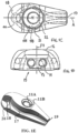
- the nozzle 10 exhibits mirror symmetry about a first plane P3 containing a longitudinal axis A of the nozzle as can be seen, for example, in FIG. 1D .
- the nozzle may be a one-piece unit.
- the nozzle includes a forward end 13, a rear end 14 and a bottom face 15.
- the bottom face 15 comprises a first surface 15A and a second surface 15B, the first surface being generally recessed relative to the second surface.
- a single through hole 11 extends between the bottom face 15 or the second surface 15B and an opposite top face 16.
- the single through hole 11 may be surrounded by an enlarged cavity 11A at the top face 16.
- At least one internal coolant channel 17 is provided in the nozzle that extends from a first opening 18 to a second opening 19, and is preferably not having any strength reducing or plugged holes such as stop screws in holes.
- the at least one internal coolant channel has a length.
- the first opening 18 is connectable to the coolant supply conduit 20 in the holder body.
- the first opening 18 is located at the second surface 15B of the bottom face 15.
- the second surface 15B projects such that a tangent T to the first surface 15A facing the cutting insert 5, and perpendicular to a through hole axis intersects the first opening or the channel 17.
- the first opening 18 is positioned between the through hole 11 and the rear end 13 and may comprise a chamber 26 in flow communication with the second opening 19.
- the second opening 19 serves as exit for the coolant at the forward end 13.
- the at least one coolant channel 17 and the first opening 18 are spaced from, i.e. not in contact with the through hole 11.
- the at least one coolant channel 17 may follow a smooth path without sudden directional changes such that coolant flow is not obstructed.
- At least a first portion 21 of the coolant channel 17 transits mathematically smooth or continuous into a second portion 22 of the coolant channel.
- the first and second portions of the coolant channel are designed such that first derivatives thereof are continuous if their lower peripheries are seen as mathematical curves for example as in the top view of Fig. 1C . Thereby, there will be reduced risk for oil traps when using oil mist as coolant.
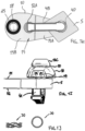
- the nozzle 10 can be held to the holder body by the fastening member 12, preferably by the screw 12A.
- the single through hole 11 receives the fastening member 12 carrying a spring 30 and that is threadedly secured to a hole 12B in the holder body.
- the cavity 11A bottom 11B is intended to serve as a seat for the spring 30, such as a multiwave compression spring of for example stainless steel. Multiwave compression springs may be used in applications where space problems in length preclude the option of using a normal compression spring.
- the spring 30 is more closely shown in FIG. 1J . Other spring means can be used such as rubber washers.
- the nozzle does not have a front projection to engage a wall of the through hole of the cutting insert.
- the coolant is led through conduits passing through the holder body and requires connecting passageways and a deformable seal to lead the coolant to a discharge exit 19.
- the fastening member 12 may have a head 12C which has an underside that can act on the spring 30 and urge the nozzle towards the holder.
- a seal element 25, such as an O-ring may be secured to or be loosely held by the nozzle or be secured to or be loosely held by a concave cavity 20A surrounding the conduit 20 opening in the holder body 2.
- the seal element 25 may be compressed between the nozzle and the holder body during the tightening of the fastening member to coolant-tightly seal the conduit 20 opening.
- the locking member 4 sits in the recess 8 by interaction of the rim 4D and the ledge 9 in a conventional manner.
- the screw 12A is passed through the spring means 30 and the nozzle hole 11 and threaded through the hole 12B in the holder body 2.
- the nozzle is rotated about the screw 12 to a position where it does not interfere with the space needed to mount the cutting insert.
- the end of the screw 12A will abut against the leg 4B and thereby cause pivotal movement of the leg 4A. If a cutting insert 5 is mounted in the pocket 3 the leg 4A will urge the cutting insert in direction towards the upstanding walls 6A and 6B.
- the nozzle is rotated about the screw into desired position when the cutting insert has been mounted.
- the screw head 12C will act on the spring means 30 and force the nozzle in direction towards the holder body.
- the nozzle will become clamped against the holder body via the interaction of the seal 25 and the concave cavity 20A.
- the nozzle first surface 15A is spaced from, i.e. not in contact with the cutting insert 5 in assembled state.
- the holder body and/or the nozzle may be provided with means to guide the nozzle to a desired direction, such as protrusions acting peripherally on the nozzle or at least one protrusion acting in the forward end of the nozzle acting centrally on the cutting insert.
- the nozzle in this embodiment is not meant to clamp on the cutting insert but can do so if for example a thicker O-ring is used instead of the O-ring 25 shown. In the latter case the nozzle will tilt about an axis perpendicular to the length axis A and the forward end thereof will contact the cutting insert.
- the bottom face 15 of the nozzle may comprise a guide device 23, such as a projection or recess, close to or at the forward end 13 to direct the nozzle and thereby direct a coolant jet by having the guide device releasably cooperating with a recess or projection on a cutting insert or at a clamping means such as the locking member 4.
- the projection 23 may be part of the forward end 13 or spaced from it by a distance that is less than a half length of the nozzle.
- the projection is formed close to the forward end like in for example FIG. 1B for best guidance of the coolant.
- the nozzle 10 can be produced by a process from the group of the rapid prototyping processes.
- the nozzle may be made through additive manufacturing such as metal 3D printing processes which use binders, or fully dense metal processes like selective laser sintering (SLS) or direct metal laser sintering (DMLS).
- SLS selective laser sintering
- DMLS direct metal laser sintering
- the latter technology uses a high power laser to fuse small particles of metal powders into a nozzle that has the described three dimensional shape. A laser beam "draws" directly on the powder so that only selected portions of the powder are solidified. The powder is said to be "scanned” by the laser.
- the use of a laser in this manner allows layers of different shape to be easily and rapidly fused, enabling complex objects with intricate internal structures to be produced.
- the laser selectively fuses the powdered metal by scanning the cross-sections (or layers) generated by a three dimensional modeling program on the surface of a powder bed. After each cross-section is scanned, the powder bed is lowered by one layer thickness. Then a new layer of material is applied on top and the process is repeated until the nozzle is completed.
- the rapid prototyping process makes it possible to produce complex nozzles which may or may not require subsequent machining.
- FIGS. 1L, 1M and 1N schematically show the channel 17 made by a rapid prototyping process, wherein layers 40 have been stacked upon each other to produce the internal channel by fusing material around non-fused powder. The non-fused powder is removed when the nozzle is completed.
- the joint 41 between two adjacent layers produces a visible step or groove 42.
- the grooves extend internally at least partially along the coolant channel.
- the axial extensions of the grooves 42 are chosen to coincide with the flow direction F of the coolant or central axis of the channel 17 to a largest possible degree, i.e. a direction of the joints 41 or grooves 42 coincides along least at half of the length of the channel to reduce flow obstruction.
- the joints 41 coincide with the flow direction along at least 80% of the length of the channel, see exemplary line 41 in FIG. 1B .
- the size S of the groove 42 may vary in the range of 0.1 to 30 micrometers or be constant in the range of 0.1 to 30 micrometers. The size may depend on the resolution of the manufacturing equipment being used. By having grooves or steps aligned with the flow direction the flow of coolant will be unobstructed.
- the terms "coincide” or “aligned” here include that small deviations from the ideal path, such as about ⁇ 5 degrees, are acceptable.
- the shown tool will be turning metal workpieces while coolant may flow in order through the holder body 2, the coolant supply conduit 20, the seal 30, the fluid channel 17 and from the exit 19 to at least one active cutting edge.
- a single fastening member 12 or screw 12A secures both the cutting insert 5 and the nozzle 10.
- Tool life generally increases with increase in coolant supply pressure. This can be attributed to the ability of the high-pressure coolant to lift the chip and gain access closer to the cutting interface. This action leads to a reduction of the seizure region, thus lowering the friction coefficient, which in turn results in reduction in cutting temperature and cutting forces.
- the pressure used in the discussed embodiments is above 30 bar, often above 100 bar coolant pressure.
- the coolant channel 17 may have a diameter, for example in the range of 0.1 mm to 8 mm.
- the present invention provides a cutting tool and a nozzle which can be produced flexibly and with relatively complex structures in a simple and cost-effective process.
- the coolant channel may have a changing cross-section. With a changing cross-section, it is possible to divide the volumetric flow of the coolant in a desired manner between several different coolant channels in the nozzle. It is possible to reduce the size of the outlet opening 19 of the coolant channel 17 such to increase coolant speed. Thus, the size of the second opening 19 of the coolant channel 17 may define the smallest diameter of the coolant channel.
Description
- The present invention relates to a nozzle and a cutting tool arranged for metal chip removing machining and, more particularly, to such cutting tools having coolant flow channels.
- It is advantageous to deliver a coolant closely to a cutting area, using a cutting tool having a coolant supply, directing a coolant to a cutting edge of the cutting insert for minimizing the heat accumulated due to the interaction of a cutting insert with a machined workpiece. Conventional techniques for providing lubrication and/or coolant to cutting edges of cutting inserts typically involve introducing the coolant via openings in a toolholder for the cutting insert, or via spray nozzles directed at the cutting edges such as
US 4,848,198 . Some cutting inserts include channels formed in the cutting inserts that are in flow communication with and facilitate introduction of coolant from channels provided in the toolholder body. The provision of these coolant flow channels in the cutting inserts tends to substantially complicate manufacture of the cutting inserts, and the channels can weaken the cutting insert. It is desirable to provide a cutting tool that facilitate introduction of coolant to the cutting edges of the cutting insert that minimizes manufacturing complexity. It is also desirable to provide a cutting tool and a nozzle that facilitate introduction of coolant to the cutting edge without substantially interfering with the strength of the cutting insert.WO9620650 US 2013/220089 A1 discloses a cutting tool provided with an internal fluid delivery system comprising a fluid delivery head where the fluid path coincides with a through bore for a fastening element in the fluid delivery head. - According to the present invention, a nozzle is provided for introduction of coolant to a cutting edge for metal chip removing machining, said nozzle having a single through hole for a fastening member and having at least one internal coolant channel for fluid having a flow direction, the at least one internal coolant channel having a length, wherein the at least one internal coolant channel comprises grooves extending internally at least partially along the coolant channel for enhanced flow properties, the at least one internal coolant channel extending from a first opening to a second opening, said first opening is connectable to a coolant supply conduit in the holder body, said second opening serving as exit for the coolant at the forward end, said nozzle having a forward end, a rear end and a bottom face, said through hole extending between the bottom face and an opposite top face, wherein the at least one internal coolant channel and the first opening are spaced from the single through hole to avoid interference therewith.
- According to a further aspect of the present invention, a cutting tool for metal chip removing machining is provided, wherein the cutting tool has a holder body, a cutting insert and a nozzle as described above.
- According to another aspect of the present invention, the direction of the grooves coincides with the flow direction at least along half of the length of the at least one internal coolant channel to reduce obstruction of the flow of coolant.
- According to another aspect of the present invention, the the grooves coincide with the flow direction along at least 80% of the length of the at least one internal coolant channel to further reduce obstruction of the flow of coolant.
- According to another aspect of the present invention, a size of the groove is in the range of 0.1 to 30 micrometers.
- According to another aspect of the present invention, the at least one internal coolant channel has a changing cross-section to divide the volumetric flow of the coolant.
- According to another aspect of the present invention, the at least one internal coolant channel has a diameter, in the range of 0.1 mm to 8 mm.
- According to another aspect of the present invention, the size of the second opening of the at least one internal coolant channel defines the smallest diameter of the at least one internal coolant channel such to increase coolant speed.
- According to another aspect of the present invention, the nozzle is a removable nozzle for turning applications where coolant cools the cutting insert and the cutting tool comprises means to coolant-tightly seal the nozzle relative to the holder body to avoid leakage of coolant.
- According to another aspect of the present invention, the at least one internal coolant channel follows a smooth path without sudden directional changes thereby enhancing coolant flow.
- According to another aspect of the present invention, there are two internal coolant channels extending at opposite sides of the single through hole thereby facilitating increase in coolant flow while keeping the nozzle sturdy.
- According to another aspect of the present invention, the first opening is situated between the single through hole and the rear end to make more space for fastening means.
- According to another aspect of the present invention, the bottom face of the nozzle comprises a guide device such as a projection or recess adjacent to the forward end to set the direction of the nozzle by having the guide device cooperating with a recess or projection on the cutting insert or a clamping means.
- According to another aspect of the present invention, the nozzle is a one-piece unit made through additive manufacturing, such that it has no plugged holes.
- According to another aspect of the present invention, a single fastening member or screw secures both the cutting insert and the nozzle.
- The features and advantages of the present invention are well understood by reading the following detailed description in conjunction with the drawings in which like numerals indicate similar elements and in which:
-
FIG. 1A is a perspective view of a cutting tool according to an aspect of the present invention; -
FIG. 1B is a side view of a nozzle of the cutting tool inFig. 1A ; -
FIG. 1C is a top view of the nozzle; -
FIG. 1D is a front view of the nozzle; -
FIG. 1E is a perspective front view of the nozzle, partially in section; -
FIG. 1F is an exploded side view of components including the nozzle ofFigs. 1B-1E of the cutting tool according to an aspect of the present invention; -
FIG. 1G is a side view of the components; -
FIG. 1H is a bottom view of the components; -
FIG. 1I is a front view of the components; -
FIG. 1J is a side view and top view of a spring included in the components; -
FIG. 1K is a top view of a holder body of the cutting tool inFig. 1A ; -
FIG. 1L is a cross-sectional view of a channel in the nozzle; -
FIG. 1M is an enlarged view of the cross-section view inFIG. 1L ; and -
FIG. 1N is an side view according to the arrow N inFIG. 1M , - Reference is made to
FIGS. 1A-1N showing a cutting tool 1 and anozzle 10 in accordance with the present invention. The shown cutting tool 1 may be a turning tool for internal metal machining and comprises aholder body 2 having apocket 3, a clamping means in the shape of a lockingmember 4 and an inducer ornozzle 10. Thepocket 3 is conventional and may have a bottom surface 7 and twoupstanding walls member 4. The bottom surface may be provided with a removable shim, not shown. The recess 8 is key lock shaped in top view, e.g. a combination of a circle and a rectangle, and may have a ledge 9 below about a center of the bottom surface 7. Theindexable cutting insert 5 is clamped in the pocket by means of an L-shapedlocking member 4 projecting into a hole of the cutting insert. In the illustrated embodiment, the cutting insert and pocket are generally diamond in shape but may have other shapes. The L-shaped locking member urges the converging sides of the cuttinginsert 5 againstupstanding walls leg 4B of an L-shape pivotally arranged in the recess 8 in theholder 2, theother leg 4A of which member extends through a hole of the cuttinginsert 5. The locking member may have a rim 4D which rests upon the ledge 9 in the recess 8. Actuating means or fastening means 12 is provided to move theleg 4B downwardly and by this cause a pivoting action of the locking member around an axis and about a fulcrum point of the rim 4D and the ledge 9. The said axis forms substantially a right angle with the direction in which theleg 4B extends. In the illustrated embodiment, themeans 12 is in the form of ascrew 12A threadably engaged in ahole 12B in theholder 2. Thescrew 12A may have a single threaded end portion and may have an end portion arranged to engage thefree end 4C of theleg 4B of the L-shapedlocking member 4, when thescrew 12A is turned, to cause said pivoting action of the locking member around the fulcrum point formed in theholder 2. Theleg 4A passes through the recess 8 in the holder, the opening being shaped and dimensioned so as not to impede desired pivotal movement of the legs. The lockingmember leg 4A extends into a central hole in the cutting insert and serves to detachably secure the cutting insert in thepocket 3. The pivotal movement of theleg 4A causes thecutting insert 5 to move towards thewalls - The
screw 12A may extend along ahole 12B in theholder body 2. The screw is intersected by upper (P1) and lower (P2) imaginary planes of the cutting insert. The planes P1 and P2 may be parallel and each plane may touch at least two, preferably three or four, corner portions of the upper and lower surface of the cutting insert, respectively. Thenozzle 10 exhibits mirror symmetry about a first plane P3 containing a longitudinal axis A of the nozzle as can be seen, for example, inFIG. 1D . The nozzle may be a one-piece unit. The nozzle includes aforward end 13, arear end 14 and abottom face 15. Thebottom face 15 comprises afirst surface 15A and a second surface 15B, the first surface being generally recessed relative to the second surface. A single through hole 11 extends between thebottom face 15 or the second surface 15B and an oppositetop face 16. The single through hole 11 may be surrounded by anenlarged cavity 11A at thetop face 16. At least oneinternal coolant channel 17 is provided in the nozzle that extends from afirst opening 18 to asecond opening 19, and is preferably not having any strength reducing or plugged holes such as stop screws in holes. The at least one internal coolant channel has a length. Thefirst opening 18 is connectable to thecoolant supply conduit 20 in the holder body. Thefirst opening 18 is located at the second surface 15B of thebottom face 15. The second surface 15B projects such that a tangent T to thefirst surface 15A facing the cuttinginsert 5, and perpendicular to a through hole axis intersects the first opening or thechannel 17. Thefirst opening 18 is positioned between the through hole 11 and therear end 13 and may comprise a chamber 26 in flow communication with thesecond opening 19. Thesecond opening 19 serves as exit for the coolant at theforward end 13. The at least onecoolant channel 17 and thefirst opening 18 are spaced from, i.e. not in contact with the through hole 11. The at least onecoolant channel 17 may follow a smooth path without sudden directional changes such that coolant flow is not obstructed. At least afirst portion 21 of thecoolant channel 17 transits mathematically smooth or continuous into asecond portion 22 of the coolant channel. The first and second portions of the coolant channel are designed such that first derivatives thereof are continuous if their lower peripheries are seen as mathematical curves for example as in the top view ofFig. 1C . Thereby, there will be reduced risk for oil traps when using oil mist as coolant. - The
nozzle 10 can be held to the holder body by thefastening member 12, preferably by thescrew 12A. The single through hole 11 receives thefastening member 12 carrying aspring 30 and that is threadedly secured to ahole 12B in the holder body. Thecavity 11A bottomspring 30, such as a multiwave compression spring of for example stainless steel. Multiwave compression springs may be used in applications where space problems in length preclude the option of using a normal compression spring. Thespring 30 is more closely shown inFIG. 1J . Other spring means can be used such as rubber washers. The nozzle does not have a front projection to engage a wall of the through hole of the cutting insert. The coolant is led through conduits passing through the holder body and requires connecting passageways and a deformable seal to lead the coolant to adischarge exit 19. - The
fastening member 12 may have ahead 12C which has an underside that can act on thespring 30 and urge the nozzle towards the holder. Aseal element 25, such as an O-ring may be secured to or be loosely held by the nozzle or be secured to or be loosely held by aconcave cavity 20A surrounding theconduit 20 opening in theholder body 2. Theseal element 25 may be compressed between the nozzle and the holder body during the tightening of the fastening member to coolant-tightly seal theconduit 20 opening. - At mounting of the cutting
insert 5 to theholder body 2 the lockingmember 4 sits in the recess 8 by interaction of the rim 4D and the ledge 9 in a conventional manner. Thescrew 12A is passed through the spring means 30 and the nozzle hole 11 and threaded through thehole 12B in theholder body 2. Suitably, the nozzle is rotated about thescrew 12 to a position where it does not interfere with the space needed to mount the cutting insert. The end of thescrew 12A will abut against theleg 4B and thereby cause pivotal movement of theleg 4A. If acutting insert 5 is mounted in thepocket 3 theleg 4A will urge the cutting insert in direction towards theupstanding walls screw head 12C will act on the spring means 30 and force the nozzle in direction towards the holder body. By choosing the correct elasticity property for the spring means 30 and the correct direction of the nozzle, the nozzle will become clamped against the holder body via the interaction of theseal 25 and theconcave cavity 20A. The nozzlefirst surface 15A is spaced from, i.e. not in contact with the cuttinginsert 5 in assembled state. The holder body and/or the nozzle may be provided with means to guide the nozzle to a desired direction, such as protrusions acting peripherally on the nozzle or at least one protrusion acting in the forward end of the nozzle acting centrally on the cutting insert. The nozzle in this embodiment is not meant to clamp on the cutting insert but can do so if for example a thicker O-ring is used instead of the O-ring 25 shown. In the latter case the nozzle will tilt about an axis perpendicular to the length axis A and the forward end thereof will contact the cutting insert. - The
bottom face 15 of the nozzle may comprise a guide device 23, such as a projection or recess, close to or at theforward end 13 to direct the nozzle and thereby direct a coolant jet by having the guide device releasably cooperating with a recess or projection on a cutting insert or at a clamping means such as the lockingmember 4. The projection 23 may be part of theforward end 13 or spaced from it by a distance that is less than a half length of the nozzle. Preferably the projection is formed close to the forward end like in for exampleFIG. 1B for best guidance of the coolant. - The
nozzle 10 can be produced by a process from the group of the rapid prototyping processes. The nozzle may be made through additive manufacturing such as metal 3D printing processes which use binders, or fully dense metal processes like selective laser sintering (SLS) or direct metal laser sintering (DMLS). The latter technology uses a high power laser to fuse small particles of metal powders into a nozzle that has the described three dimensional shape. A laser beam "draws" directly on the powder so that only selected portions of the powder are solidified. The powder is said to be "scanned" by the laser. The use of a laser in this manner allows layers of different shape to be easily and rapidly fused, enabling complex objects with intricate internal structures to be produced. The laser selectively fuses the powdered metal by scanning the cross-sections (or layers) generated by a three dimensional modeling program on the surface of a powder bed. After each cross-section is scanned, the powder bed is lowered by one layer thickness. Then a new layer of material is applied on top and the process is repeated until the nozzle is completed. The rapid prototyping process makes it possible to produce complex nozzles which may or may not require subsequent machining.FIGS. 1L, 1M and 1N schematically show thechannel 17 made by a rapid prototyping process, wherein layers 40 have been stacked upon each other to produce the internal channel by fusing material around non-fused powder. The non-fused powder is removed when the nozzle is completed. The joint 41 between two adjacent layers produces a visible step orgroove 42. The grooves extend internally at least partially along the coolant channel. The axial extensions of thegrooves 42 are chosen to coincide with the flow direction F of the coolant or central axis of thechannel 17 to a largest possible degree, i.e. a direction of thejoints 41 orgrooves 42 coincides along least at half of the length of the channel to reduce flow obstruction. Thejoints 41 coincide with the flow direction along at least 80% of the length of the channel, seeexemplary line 41 inFIG. 1B . The size S of thegroove 42 may vary in the range of 0.1 to 30 micrometers or be constant in the range of 0.1 to 30 micrometers. The size may depend on the resolution of the manufacturing equipment being used. By having grooves or steps aligned with the flow direction the flow of coolant will be unobstructed. The terms "coincide" or "aligned" here include that small deviations from the ideal path, such as about ±5 degrees, are acceptable. - In use the shown tool will be turning metal workpieces while coolant may flow in order through the
holder body 2, thecoolant supply conduit 20, theseal 30, thefluid channel 17 and from theexit 19 to at least one active cutting edge. - Stated another way, a
single fastening member 12 orscrew 12A secures both the cuttinginsert 5 and thenozzle 10. - Tool life generally increases with increase in coolant supply pressure. This can be attributed to the ability of the high-pressure coolant to lift the chip and gain access closer to the cutting interface. This action leads to a reduction of the seizure region, thus lowering the friction coefficient, which in turn results in reduction in cutting temperature and cutting forces. Preferably the pressure used in the discussed embodiments is above 30 bar, often above 100 bar coolant pressure.
- The
coolant channel 17 may have a diameter, for example in the range of 0.1 mm to 8 mm. - Thus the present invention provides a cutting tool and a nozzle which can be produced flexibly and with relatively complex structures in a simple and cost-effective process. The coolant channel may have a changing cross-section. With a changing cross-section, it is possible to divide the volumetric flow of the coolant in a desired manner between several different coolant channels in the nozzle. It is possible to reduce the size of the outlet opening 19 of the
coolant channel 17 such to increase coolant speed. Thus, the size of thesecond opening 19 of thecoolant channel 17 may define the smallest diameter of the coolant channel. - In some cases it can be beneficial to use this solution regarding the grooved coolant channel in milling cutters and drilling tools too.
- In the present application, the use of terms such as "including" is open-ended and is intended to have the same meaning as terms such as "comprising" and not preclude the presence of other structure, material, or acts. Similarly, though the use of terms such as "can" or "may" is intended to be open-ended and to reflect that structure, material, or acts are not necessary, the failure to use such terms is not intended to reflect that structure, material, or acts are essential. To the extent that structure, material, or acts are presently considered to be essential, they are identified as such. Terms such as "upper", "lower", "top", "bottom", "forward" and "rear" refer to features as shown in the current drawings and as perceived by the skilled person.
Claims (15)
- A nozzle (10) for introduction of coolant to a cutting edge for metal chip removing machining, said nozzle (10) having a single through hole (11) for a fastening member (12) and having at least one internal coolant channel (17) for fluid having a flow direction (F), the at least one internal coolant channel (17) having a length, wherein the at least one internal coolant channel (17) comprises grooves (42) extending internally at least partially along the coolant channel (17), the at least one internal coolant channel (17) extending from a first opening (18) to a second opening (19;19';19"), said first opening (18) is connectable to a coolant supply conduit (20) in a holder body (2), said second opening (19;19';19") serving as exit for the coolant at the forward end (13), said nozzle (10) having a forward end (13), a rear end (14) and a bottom face (15), said single through hole (11) extending between the bottom face (15) and an opposite top face (16), characterized in that the at least one internal coolant channel (17) and the first opening (18) are spaced from the single through hole (11).
- A cutting tool (1) for metal chip removing machining, wherein the cutting tool (1) has a holder body (2), a cutting insert (5) and a nozzle (10) according to claim 1.
- The cutting tool (1) according to claim 2, wherein a direction of the grooves (42) coincides with the flow direction (F) at least along half of the length of the at least one internal coolant channel (17).
- The cutting tool according to claim 2 or 3, wherein the grooves (42) coincide with the flow direction (F) along at least 80% of the length of the at least one internal coolant channel (17).
- The cutting tool (1) according to claim 2, 3 or 4, wherein a size (S) of the groove (42) is in the range of 0.1 to 30 micrometers.
- The cutting tool (1) according to anyone of claims 2-5, wherein the at least one internal coolant channel (17) has a changing cross-section.
- The cutting tool (1) according to anyone of claims 2-6, wherein the at least one internal coolant channel (17) has a diameter, in the range of 0.1 mm to 8 mm.
- The cutting tool (1) according to anyone of claims 2-7, wherein the size of the second opening (19) of the at least one internal coolant channel (17) defines the smallest diameter of the at least one internal coolant channel (17).
- The cutting tool (1) according to anyone of claims 2 - 8, wherein the nozzle (10) is a removable nozzle for turning applications and wherein the cutting tool (1) comprises means (25) to coolant-tightly seal the nozzle (10) relative to the holder body (2).
- The cutting tool (1) according to anyone of claims 2-9, wherein the at least one internal coolant channel (17) follows a smooth path without sudden directional changes.
- The cutting tool (1) according to anyone of claims 2 - 10, wherein there are two internal coolant channels (17) extending at opposite sides of the single through hole (11).
- The cutting tool (1) according to anyone of claims 2 - 11, wherein the first opening (18) is situated between the single through hole (11) and the rear end (14).
- The cutting tool (1) according to anyone of claims 2 - 12, wherein the bottom face (15) of the nozzle (10) comprises a guide device (23) such as a projection or recess adjacent to the forward end (13) to set the direction of the nozzle (10) by having the guide device (23) cooperating with a recess or projection on the cutting insert (5) or a clamping means.
- The cutting tool (1) according to anyone of claims 2 - 13, wherein the nozzle (10) is a one-piece unit made through additive manufacturing.
- The cutting tool (1) according to anyone of claims 2 - 14, wherein a single fastening member (12) or screw (12A) secures both the cutting insert (5) and the nozzle (10).
Priority Applications (9)
| Application Number | Priority Date | Filing Date | Title |
|---|---|---|---|
| EP15174654.2A EP3112062B1 (en) | 2015-06-30 | 2015-06-30 | A cutting tool |
| CN201680038251.6A CN107708900B (en) | 2015-06-30 | 2016-06-02 | Cutting tool with nozzle with internal coolant channel |
| PCT/SE2016/050522 WO2017003342A1 (en) | 2015-06-30 | 2016-06-02 | A cutting tool with a nozzle with a coolant channel |
| KR1020177037866A KR102495697B1 (en) | 2015-06-30 | 2016-06-02 | A cutting tool with a nozzle with a coolant channel |
| US15/738,768 US10596634B2 (en) | 2015-06-30 | 2016-06-02 | Cutting tool with a nozzle with a coolant channel |
| PCT/SE2016/050523 WO2017003343A1 (en) | 2015-06-30 | 2016-06-02 | A cutting tool and a nozzle with internally extending grooves |
| KR1020177037601A KR102482322B1 (en) | 2015-06-30 | 2016-06-02 | A cutting tool and a nozzle with internally extending grooves |
| CN201680038241.2A CN107708899B (en) | 2015-06-30 | 2016-06-02 | Cutting tool and nozzle with internally extending grooves |
| US15/738,744 US10946452B2 (en) | 2015-06-30 | 2016-06-02 | Cutting tool and a nozzle with internally extending grooves |
Applications Claiming Priority (1)
| Application Number | Priority Date | Filing Date | Title |
|---|---|---|---|
| EP15174654.2A EP3112062B1 (en) | 2015-06-30 | 2015-06-30 | A cutting tool |
Publications (2)
| Publication Number | Publication Date |
|---|---|
| EP3112062A1 EP3112062A1 (en) | 2017-01-04 |
| EP3112062B1 true EP3112062B1 (en) | 2023-06-21 |
Family
ID=53496558
Family Applications (1)
| Application Number | Title | Priority Date | Filing Date |
|---|---|---|---|
| EP15174654.2A Active EP3112062B1 (en) | 2015-06-30 | 2015-06-30 | A cutting tool |
Country Status (1)
| Country | Link |
|---|---|
| EP (1) | EP3112062B1 (en) |
Families Citing this family (3)
| Publication number | Priority date | Publication date | Assignee | Title |
|---|---|---|---|---|
| CN109202109B (en) * | 2017-07-07 | 2020-03-17 | 黄宪仁 | Structure of turning tool rest |
| DE102017123786A1 (en) * | 2017-10-12 | 2019-04-18 | Hartmetall-Werkzeugfabrik Paul Horn Gmbh | Holder for a grooving tool |
| MX2020006039A (en) * | 2018-04-30 | 2021-08-06 | Horn P Hartmetall Werkzeugfab | Tool for machining a workpiece. |
Citations (4)
| Publication number | Priority date | Publication date | Assignee | Title |
|---|---|---|---|---|
| US4640652A (en) * | 1986-06-30 | 1987-02-03 | Scully-Jones Corp. | Coolant delivery system |
| US20110305531A1 (en) * | 2010-06-10 | 2011-12-15 | Iscar, Ltd. | Cutting Tool and Shaped Coolant Outlet Therefor |
| US20120163931A1 (en) * | 2009-08-25 | 2012-06-28 | Arno Friedrichs | Tool |
| US20130220089A1 (en) * | 2012-02-23 | 2013-08-29 | Iscar, Ltd. | Cutting tool with internal fluid delivery system |
Family Cites Families (2)
| Publication number | Priority date | Publication date | Assignee | Title |
|---|---|---|---|---|
| US4848198A (en) | 1988-04-21 | 1989-07-18 | Kennametal Inc. | Chip breaking tool holder |
| WO1996020650A1 (en) * | 1995-01-06 | 1996-07-11 | Synthes Ag, Chur | Cooled drill bushing |
-
2015
- 2015-06-30 EP EP15174654.2A patent/EP3112062B1/en active Active
Patent Citations (4)
| Publication number | Priority date | Publication date | Assignee | Title |
|---|---|---|---|---|
| US4640652A (en) * | 1986-06-30 | 1987-02-03 | Scully-Jones Corp. | Coolant delivery system |
| US20120163931A1 (en) * | 2009-08-25 | 2012-06-28 | Arno Friedrichs | Tool |
| US20110305531A1 (en) * | 2010-06-10 | 2011-12-15 | Iscar, Ltd. | Cutting Tool and Shaped Coolant Outlet Therefor |
| US20130220089A1 (en) * | 2012-02-23 | 2013-08-29 | Iscar, Ltd. | Cutting tool with internal fluid delivery system |
Also Published As
| Publication number | Publication date |
|---|---|
| EP3112062A1 (en) | 2017-01-04 |
Similar Documents
| Publication | Publication Date | Title |
|---|---|---|
| US10946452B2 (en) | Cutting tool and a nozzle with internally extending grooves | |
| EP3112063B1 (en) | A cutting tool | |
| EP3112062B1 (en) | A cutting tool | |
| WO2010050228A1 (en) | Cutting tool configured so that insert can be removably mounted thereto | |
| JP6651136B2 (en) | Cutting inserts, deposits and holders | |
| JP7049340B2 (en) | Anvil with curved walkways for cutting tools | |
| EP0741634A1 (en) | Cutting tool assembly having an exchangeable adaptor | |
| CN110214063B (en) | Cutting plate part for metal cutting grooving tool | |
| JP2015000474A (en) | Cutting tool assembly having clamp assembly comprising clamp and coolant plate | |
| WO2019069924A1 (en) | Cutting tool and method for manufacturing cut article | |
| CN108463302B (en) | Metal cutting tool holder and method of machining a metal workpiece by a turning operation | |
| CN111163887A (en) | Tool for chip removing machining | |
| JP6961151B1 (en) | Turning tool | |
| CN109070248A (en) | Play the tool of machining | |
| US20230201929A1 (en) | Turning toolholder with enhanced coolant delivery system | |
| JP2010533593A (en) | Tool holder with cutting insert | |
| CA3154058C (en) | Material feeding device | |
| WO2024075522A1 (en) | Cutting tip holder and cutting tool | |
| KR20220136672A (en) | Machine tool with adjustable machining angle | |
| CA3154058A1 (en) | Material feeding device | |
| CN116348226A (en) | Tool holder, cutting tool, and method for manufacturing cut product | |
| Schulz et al. | Identification of dimension in phase space for cutting |
Legal Events
| Date | Code | Title | Description |
|---|---|---|---|
| PUAI | Public reference made under article 153(3) epc to a published international application that has entered the european phase |
Free format text: ORIGINAL CODE: 0009012 |
|
| STAA | Information on the status of an ep patent application or granted ep patent |
Free format text: STATUS: THE APPLICATION HAS BEEN PUBLISHED |
|
| AK | Designated contracting states |
Kind code of ref document: A1 Designated state(s): AL AT BE BG CH CY CZ DE DK EE ES FI FR GB GR HR HU IE IS IT LI LT LU LV MC MK MT NL NO PL PT RO RS SE SI SK SM TR |
|
| AX | Request for extension of the european patent |
Extension state: BA ME |
|
| STAA | Information on the status of an ep patent application or granted ep patent |
Free format text: STATUS: REQUEST FOR EXAMINATION WAS MADE |
|
| 17P | Request for examination filed |
Effective date: 20170704 |
|
| RBV | Designated contracting states (corrected) |
Designated state(s): AL AT BE BG CH CY CZ DE DK EE ES FI FR GB GR HR HU IE IS IT LI LT LU LV MC MK MT NL NO PL PT RO RS SE SI SK SM TR |
|
| STAA | Information on the status of an ep patent application or granted ep patent |
Free format text: STATUS: EXAMINATION IS IN PROGRESS |
|
| 17Q | First examination report despatched |
Effective date: 20210713 |
|
| STAA | Information on the status of an ep patent application or granted ep patent |
Free format text: STATUS: EXAMINATION IS IN PROGRESS |
|
| REG | Reference to a national code |
Ref country code: DE Ref legal event code: R079 Ref document number: 602015084249 Country of ref document: DE Free format text: PREVIOUS MAIN CLASS: B23B0027100000 Ipc: B33Y0080000000 Ref country code: DE Ref legal event code: R079 Free format text: PREVIOUS MAIN CLASS: B23B0027100000 Ipc: B33Y0080000000 |
|
| GRAP | Despatch of communication of intention to grant a patent |
Free format text: ORIGINAL CODE: EPIDOSNIGR1 |
|
| STAA | Information on the status of an ep patent application or granted ep patent |
Free format text: STATUS: GRANT OF PATENT IS INTENDED |
|
| RIC1 | Information provided on ipc code assigned before grant |
Ipc: B33Y 80/00 20150101AFI20230109BHEP |
|
| INTG | Intention to grant announced |
Effective date: 20230124 |
|
| GRAS | Grant fee paid |
Free format text: ORIGINAL CODE: EPIDOSNIGR3 |
|
| GRAA | (expected) grant |
Free format text: ORIGINAL CODE: 0009210 |
|
| STAA | Information on the status of an ep patent application or granted ep patent |
Free format text: STATUS: THE PATENT HAS BEEN GRANTED |
|
| AK | Designated contracting states |
Kind code of ref document: B1 Designated state(s): AL AT BE BG CH CY CZ DE DK EE ES FI FR GB GR HR HU IE IS IT LI LT LU LV MC MK MT NL NO PL PT RO RS SE SI SK SM TR |
|
| REG | Reference to a national code |
Ref country code: CH Ref legal event code: EP |
|
| REG | Reference to a national code |
Ref country code: DE Ref legal event code: R096 Ref document number: 602015084249 Country of ref document: DE |
|
| REG | Reference to a national code |
Ref country code: AT Ref legal event code: REF Ref document number: 1580655 Country of ref document: AT Kind code of ref document: T Effective date: 20230715 |
|
| REG | Reference to a national code |
Ref country code: IE Ref legal event code: FG4D |
|
| REG | Reference to a national code |
Ref country code: LT Ref legal event code: MG9D |
|
| REG | Reference to a national code |
Ref country code: NL Ref legal event code: MP Effective date: 20230621 |
|
| PG25 | Lapsed in a contracting state [announced via postgrant information from national office to epo] |
Ref country code: SE Free format text: LAPSE BECAUSE OF FAILURE TO SUBMIT A TRANSLATION OF THE DESCRIPTION OR TO PAY THE FEE WITHIN THE PRESCRIBED TIME-LIMIT Effective date: 20230621 Ref country code: NO Free format text: LAPSE BECAUSE OF FAILURE TO SUBMIT A TRANSLATION OF THE DESCRIPTION OR TO PAY THE FEE WITHIN THE PRESCRIBED TIME-LIMIT Effective date: 20230921 |
|
| PGFP | Annual fee paid to national office [announced via postgrant information from national office to epo] |
Ref country code: GB Payment date: 20230824 Year of fee payment: 9 |
|
| REG | Reference to a national code |
Ref country code: AT Ref legal event code: MK05 Ref document number: 1580655 Country of ref document: AT Kind code of ref document: T Effective date: 20230621 |
|
| PG25 | Lapsed in a contracting state [announced via postgrant information from national office to epo] |
Ref country code: RS Free format text: LAPSE BECAUSE OF FAILURE TO SUBMIT A TRANSLATION OF THE DESCRIPTION OR TO PAY THE FEE WITHIN THE PRESCRIBED TIME-LIMIT Effective date: 20230621 Ref country code: NL Free format text: LAPSE BECAUSE OF FAILURE TO SUBMIT A TRANSLATION OF THE DESCRIPTION OR TO PAY THE FEE WITHIN THE PRESCRIBED TIME-LIMIT Effective date: 20230621 Ref country code: LV Free format text: LAPSE BECAUSE OF FAILURE TO SUBMIT A TRANSLATION OF THE DESCRIPTION OR TO PAY THE FEE WITHIN THE PRESCRIBED TIME-LIMIT Effective date: 20230621 Ref country code: LT Free format text: LAPSE BECAUSE OF FAILURE TO SUBMIT A TRANSLATION OF THE DESCRIPTION OR TO PAY THE FEE WITHIN THE PRESCRIBED TIME-LIMIT Effective date: 20230621 Ref country code: HR Free format text: LAPSE BECAUSE OF FAILURE TO SUBMIT A TRANSLATION OF THE DESCRIPTION OR TO PAY THE FEE WITHIN THE PRESCRIBED TIME-LIMIT Effective date: 20230621 Ref country code: GR Free format text: LAPSE BECAUSE OF FAILURE TO SUBMIT A TRANSLATION OF THE DESCRIPTION OR TO PAY THE FEE WITHIN THE PRESCRIBED TIME-LIMIT Effective date: 20230922 |
|
| PGFP | Annual fee paid to national office [announced via postgrant information from national office to epo] |
Ref country code: FR Payment date: 20230927 Year of fee payment: 9 Ref country code: DE Payment date: 20230830 Year of fee payment: 9 |
|
| P01 | Opt-out of the competence of the unified patent court (upc) registered |
Effective date: 20231115 |
|
| PG25 | Lapsed in a contracting state [announced via postgrant information from national office to epo] |
Ref country code: FI Free format text: LAPSE BECAUSE OF FAILURE TO SUBMIT A TRANSLATION OF THE DESCRIPTION OR TO PAY THE FEE WITHIN THE PRESCRIBED TIME-LIMIT Effective date: 20230621 |
|
| PG25 | Lapsed in a contracting state [announced via postgrant information from national office to epo] |
Ref country code: SK Free format text: LAPSE BECAUSE OF FAILURE TO SUBMIT A TRANSLATION OF THE DESCRIPTION OR TO PAY THE FEE WITHIN THE PRESCRIBED TIME-LIMIT Effective date: 20230621 |
|
| PG25 | Lapsed in a contracting state [announced via postgrant information from national office to epo] |
Ref country code: ES Free format text: LAPSE BECAUSE OF FAILURE TO SUBMIT A TRANSLATION OF THE DESCRIPTION OR TO PAY THE FEE WITHIN THE PRESCRIBED TIME-LIMIT Effective date: 20230621 |
|
| PG25 | Lapsed in a contracting state [announced via postgrant information from national office to epo] |
Ref country code: IS Free format text: LAPSE BECAUSE OF FAILURE TO SUBMIT A TRANSLATION OF THE DESCRIPTION OR TO PAY THE FEE WITHIN THE PRESCRIBED TIME-LIMIT Effective date: 20231021 |
|
| PG25 | Lapsed in a contracting state [announced via postgrant information from national office to epo] |
Ref country code: SM Free format text: LAPSE BECAUSE OF FAILURE TO SUBMIT A TRANSLATION OF THE DESCRIPTION OR TO PAY THE FEE WITHIN THE PRESCRIBED TIME-LIMIT Effective date: 20230621 Ref country code: SK Free format text: LAPSE BECAUSE OF FAILURE TO SUBMIT A TRANSLATION OF THE DESCRIPTION OR TO PAY THE FEE WITHIN THE PRESCRIBED TIME-LIMIT Effective date: 20230621 Ref country code: RO Free format text: LAPSE BECAUSE OF FAILURE TO SUBMIT A TRANSLATION OF THE DESCRIPTION OR TO PAY THE FEE WITHIN THE PRESCRIBED TIME-LIMIT Effective date: 20230621 Ref country code: PT Free format text: LAPSE BECAUSE OF FAILURE TO SUBMIT A TRANSLATION OF THE DESCRIPTION OR TO PAY THE FEE WITHIN THE PRESCRIBED TIME-LIMIT Effective date: 20231023 Ref country code: IS Free format text: LAPSE BECAUSE OF FAILURE TO SUBMIT A TRANSLATION OF THE DESCRIPTION OR TO PAY THE FEE WITHIN THE PRESCRIBED TIME-LIMIT Effective date: 20231021 Ref country code: ES Free format text: LAPSE BECAUSE OF FAILURE TO SUBMIT A TRANSLATION OF THE DESCRIPTION OR TO PAY THE FEE WITHIN THE PRESCRIBED TIME-LIMIT Effective date: 20230621 Ref country code: EE Free format text: LAPSE BECAUSE OF FAILURE TO SUBMIT A TRANSLATION OF THE DESCRIPTION OR TO PAY THE FEE WITHIN THE PRESCRIBED TIME-LIMIT Effective date: 20230621 Ref country code: CZ Free format text: LAPSE BECAUSE OF FAILURE TO SUBMIT A TRANSLATION OF THE DESCRIPTION OR TO PAY THE FEE WITHIN THE PRESCRIBED TIME-LIMIT Effective date: 20230621 Ref country code: AT Free format text: LAPSE BECAUSE OF FAILURE TO SUBMIT A TRANSLATION OF THE DESCRIPTION OR TO PAY THE FEE WITHIN THE PRESCRIBED TIME-LIMIT Effective date: 20230621 |
|
| PGFP | Annual fee paid to national office [announced via postgrant information from national office to epo] |
Ref country code: IT Payment date: 20230929 Year of fee payment: 9 |
|
| REG | Reference to a national code |
Ref country code: CH Ref legal event code: PL |
|
| REG | Reference to a national code |
Ref country code: BE Ref legal event code: MM Effective date: 20230630 |
|
| PG25 | Lapsed in a contracting state [announced via postgrant information from national office to epo] |
Ref country code: PL Free format text: LAPSE BECAUSE OF FAILURE TO SUBMIT A TRANSLATION OF THE DESCRIPTION OR TO PAY THE FEE WITHIN THE PRESCRIBED TIME-LIMIT Effective date: 20230621 |
|
| PG25 | Lapsed in a contracting state [announced via postgrant information from national office to epo] |
Ref country code: LU Free format text: LAPSE BECAUSE OF NON-PAYMENT OF DUE FEES Effective date: 20230630 |
|
| PG25 | Lapsed in a contracting state [announced via postgrant information from national office to epo] |
Ref country code: MC Free format text: LAPSE BECAUSE OF FAILURE TO SUBMIT A TRANSLATION OF THE DESCRIPTION OR TO PAY THE FEE WITHIN THE PRESCRIBED TIME-LIMIT Effective date: 20230621 |
|
| REG | Reference to a national code |
Ref country code: DE Ref legal event code: R026 Ref document number: 602015084249 Country of ref document: DE |
|
| PLBI | Opposition filed |
Free format text: ORIGINAL CODE: 0009260 |
|
| REG | Reference to a national code |
Ref country code: IE Ref legal event code: MM4A |
|
| PG25 | Lapsed in a contracting state [announced via postgrant information from national office to epo] |
Ref country code: MC Free format text: LAPSE BECAUSE OF FAILURE TO SUBMIT A TRANSLATION OF THE DESCRIPTION OR TO PAY THE FEE WITHIN THE PRESCRIBED TIME-LIMIT Effective date: 20230621 Ref country code: LU Free format text: LAPSE BECAUSE OF NON-PAYMENT OF DUE FEES Effective date: 20230630 |
|
| PLAX | Notice of opposition and request to file observation + time limit sent |
Free format text: ORIGINAL CODE: EPIDOSNOBS2 |
|
| PG25 | Lapsed in a contracting state [announced via postgrant information from national office to epo] |
Ref country code: IE Free format text: LAPSE BECAUSE OF NON-PAYMENT OF DUE FEES Effective date: 20230630 |