EP3110570B1 - Cleaning device for a processing platen press - Google Patents
Cleaning device for a processing platen press Download PDFInfo
- Publication number
- EP3110570B1 EP3110570B1 EP15708122.5A EP15708122A EP3110570B1 EP 3110570 B1 EP3110570 B1 EP 3110570B1 EP 15708122 A EP15708122 A EP 15708122A EP 3110570 B1 EP3110570 B1 EP 3110570B1
- Authority
- EP
- European Patent Office
- Prior art keywords
- platen
- frame
- cleaning
- rotating
- rotating element
- Prior art date
- Legal status (The legal status is an assumption and is not a legal conclusion. Google has not performed a legal analysis and makes no representation as to the accuracy of the status listed.)
- Active
Links
Images





Classifications
-
- B—PERFORMING OPERATIONS; TRANSPORTING
- B29—WORKING OF PLASTICS; WORKING OF SUBSTANCES IN A PLASTIC STATE IN GENERAL
- B29C—SHAPING OR JOINING OF PLASTICS; SHAPING OF MATERIAL IN A PLASTIC STATE, NOT OTHERWISE PROVIDED FOR; AFTER-TREATMENT OF THE SHAPED PRODUCTS, e.g. REPAIRING
- B29C33/00—Moulds or cores; Details thereof or accessories therefor
- B29C33/70—Maintenance
- B29C33/72—Cleaning
-
- B—PERFORMING OPERATIONS; TRANSPORTING
- B08—CLEANING
- B08B—CLEANING IN GENERAL; PREVENTION OF FOULING IN GENERAL
- B08B1/00—Cleaning by methods involving the use of tools
- B08B1/30—Cleaning by methods involving the use of tools by movement of cleaning members over a surface
- B08B1/32—Cleaning by methods involving the use of tools by movement of cleaning members over a surface using rotary cleaning members
Definitions
- the present invention relates to a device for cleaning a platen of a processing platen press, and more particular the platens of a processing station for processing plate elements.
- the present invention further relates to a method for cleaning a platen in a processing platen press with a platen cleaning device.
- US 2011/0286820 A1 describes for example a cutting machine including a station for cutting plate elements with a cutting die. To obtain a quality cut, positioning of the plate element in the cutting station is crucial.
- US 5176075 A further describes a control mechanism for driving a movable lower platen in a platen press towards a fixed upper platen, the sheet materials being fed between them.
- the corrosion has to be removed as much as possible or corrections have to be made to the platens such that these imperfections or uneven spots are compensated. Therefore, corrosion over time affects the time needed to make a machine operational because additional set-up time is required. Further, cleaning the platen is very difficult and time consuming because the platens have large dimensions and the distance between the platens is relatively small.
- the platen press comprises a lower platen and an upper platen of which at least one is movable towards the other and wherein at least one is arranged to allow tools to process a plate element which is fed between the lower platen and the upper platen.
- the device comprises:
- the plate element is defined as being in a board or sheet material, such as paper, flat board, corrugated cardboard, laminated corrugated cardboard, flexible plastic, for example polyethylene (PE), polyethylene terephthalate (PET), bi-oriented polypropylene (BOPP) or other polymers, or still other materials.
- a board or sheet material such as paper, flat board, corrugated cardboard, laminated corrugated cardboard, flexible plastic, for example polyethylene (PE), polyethylene terephthalate (PET), bi-oriented polypropylene (BOPP) or other polymers, or still other materials.
- the plate element is subjected to a processing operation in the processing machine.
- the processing may be cutting operation, the processing machine being, by way of non-exhaustive example, a platen cutting machine.
- the processing may be an operation applied to the surface of the element, to apply graphic signs to it and/or to impart an aesthetic appearance to it.
- the processing may be an operation for creasing, embossing, structuring, hot foil stamping, affixing labels or holograms, or still other.
- This processed element could comprise a layer of varnish covering all or part of the surface.
- the device for cleaning a platen of a platen press further comprises pneumatic lifting means to execute the vertical relative movement between the frame and the lift member.
- pneumatic lifting means to execute the vertical relative movement between the frame and the lift member.
- Using a pneumatic lifting system for the relative vertical movement between frame and lift member has the advantage that limited space is needed to create high pressure on a surface to be cleaned. Furthermore, by changing the pressure of a compressed gas of the pneumatic lifting system, the pressure on the surface to be cleaned can be easily controlled. The control can further be done at a desired distance from the position where the pressure is created.
- the frame comprises moving means for moving the frame relative to the platen towards which it is positioned.
- the moving means ensure that the device can be moved between the upper and lower platen when the device is executing a force on the cleaning surface.
- the moving means are at least three balls in ball bearings arranged in the frame such that the frame contacts a surface only with the balls when positioned on that surface.
- the device for cleaning a platen of a platen press further comprises rotating means configured to use compressed gas to rotate the rotating element.
- rotating means configured to use compressed gas to rotate the rotating element.
- the rotating means is arranged to rotate the rotating element in an oscillation movement.
- the oscillation movement results in better cleaning such that less time is needed to execute a cleaning operation.
- the device for cleaning a platen of a platen press further comprises a handle connected to the frame for moving the frame relative to the lower platen or the upper platen.
- the handle is very useful to clean relatively large surfaces with a limited space between upper and lower platen.
- the handle comprises a telescopic bar.
- a handle with a telescopic bar creates a lot of flexibility compared to a long or short handle.
- the handle can be configured long to reach for away areas, short to reach nearby areas, etc.
- the handle comprises a hollow bar for guiding compressed gas towards the frame. Guiding the compressed gas within the handle avoids that the compressed gas hoses are getting damaged or that they get stuck during operation of the device.
- the handle comprises control means for controlling the lifting means and/or the rotating means. Having the control on the handle allows the user to control the lifting and/or rotating means during operation. This structure has the advantage that the lifting is controllable independent from the rotation.
- control means comprises a first display element for displaying the pressure of the compressed gas for the lifting means.
- control means comprises a first controller to control the pressure of the compressed gas for the lifting means.
- control means comprises a second display element for displaying the pressure of the rotating means.
- the control means comprises a second display element for displaying the pressure of the rotating means.
- control means comprises a second controller to control the pressure of the compressed gas for the rotating means.
- This aim is achieved according to the invention with a method comprising the steps of independent claim 19.
- the method for cleaning a platen in a platen press using a platen cleaning device as described above comprises the steps of:
- the method further comprises the step of providing cleaning product on the platen to be cleaned. Another advantage of the method is that different cleaning products can easily be used at different stages in the cleaning process. This improves the results.
- the platen to be cleaned is the upper platen or the lower platen.
- An advantage of the cleaning method with the platen cleaning device is that the lower platen as well as the upper platen can be cleaned simply be positioning the device rotated over 180o between the upper and lower platen.
- Fig. 1 shows a machine for treating a plate element or sheet 7, more particular a platen press 1.
- the platen press comprises various stations: an infeed station 2, a cutting station 3, a waste stripping station 4 and a delivery station 6.
- the plate elements, i.e. the sheets of cardboard to be cut 7, are gripped and carried across the press 1 by a conveyor.
- the conveyor is usually constituted by a gripping member, in the machine of Fig. 1 a series of grippers mounted on a transverse gripper bar 8 that can be secured to gripper bar chains 9 (represented in dotted lines in Fig. 1 ) driving the sheets to be cut 7 in the direction of Arrow F.
- the gripper bar 8 grips the sheet to be cut 7 that is in a predetermined intermediate position, and the gripper bar chains 9 bring the sheets in a rated running into the successive processing stations.
- the gripper bar chains 9 are carried and stopped periodically in a rated running so that, during a carrying each gripper bar 8 with its sheet 7 is passed from an upstream station to the adjacent downstream station.
- the positions of the stops of the gripper bars 8 are imposed by a carrying of the gripper bar chains 9 over a constant distance.
- the cutter station 3 comprises a lower movable platen 11 to which are attached the cutting counter form, and an upper fixed platen 12, having a lower face on which the cutting tool is attached, or conversely a lower fixed platen and an upper movable platen.
- the cut sheet 13 is separated from the gripper bar 8 at the delivery station 6, where the gripper bar 8 is still holding the front waste.
- the delivery station 6 is surmounted by a conveyor tape 14 intended to evacuate the front wastes of the cut sheets 13.
- the cut sheets 13 are then discharged in a stack from the press 1.
- the sheet to be cut 7 is carried by the gripper bar 8 between the fixed upper platen 12 and the vertically movable lower platen 11 of the platen press 1.
- the upper platen 12 may be movable or both may be movable. Once the sheet 7 is in position, the relative movement of the lower platen 11 and the upper platen 12 presses the sheet 7 in the blades 5 of the upper platen 12 such that the sheet 7 is die-cut in a size and shape defined by the pattern of the blades 5.
- the lower platen 11 rests on a bottom frame 17 by means of two knuckles 16 and 18 wherein each knuckle comprises an upper half-knuckle 36 and a lower half-knuckle 32.
- the knuckles 16 and 18 are moved by a connecting rod 20, 24 linked to a driven bit-stock 14.
- Figs. 3a-3c show a device, i.e. a platen cleaner 100 for cleaning the platen press 1 according to an embodiment of the invention.
- the platen cleaner 100 is used with the lower platen 11 in the open position. In this position, the height between the lower platen 11 and upper platen 12 is between 86mm to 198mm.
- the platen cleaner 100 comprises a frame 110, a lift member 120 and a rotating element 130.
- the platen cleaner 100 is arranged such that the lift member 120 can be moved vertically with respect to the frame 110 and the rotating element 130 can rotate with respect to the lift member 120 and thus also with respect to the frame 110.
- the device 100 and the frame 110 comprise moving means for moving the frame 110 relative to the surface on which it is positioned.
- the frame 110 is provided with ball bearings, each ball bearing having a single ball 112.
- the balls 112 can rotate freely in the ball bearings allowing easy movement of the frame 110 and thus the platen cleaner 100 over a surface.
- the overall height of the platen cleaner 100 is smaller than the opening between the lower platen 11 and the upper platen 12 in their open position. In a preferred embodiment, the height of the platen cleaner 100 is lower than 85mm.
- the frame 110 comprises a frame body 170 with a base 172 and four sidewalls 173, 174, 175 and 176.
- the platen cleaner 100 comprises lifting means in the form of four pneumatic cylinders 178 that are provided in the sidewalls.
- four pneumatic cylinders 178 are provided in sidewall 174 and two pneumatic cylinders 178 are provided in sidewall 176.
- other configurations of the pneumatic cylinders 178 are possible.
- Each pneumatic cylinder 178 has a cylinder input 179 and uses the power of compressed gas to create a linear motion.
- the four cylinder inputs 179 are connected by an internal pressure hose network 171 to a first compressed gas input 115.
- the pneumatic cylinders 179 each have a piston rod 160 to transfer the force to the lift member 120.
- the frame 110 further comprises four guiding cylinders 180.
- the axis of each guiding cylinder 180 is positioned perpendicular to the frame base 172.
- the guiding cylinders 180 will guide guiding bars 162 of the lift member 120 during relative movement of the lift member 120 and the frame 110.
- the inside of the frame further comprises three shafts 182 connected to the side walls of the frame body 170.
- On the shafts 182 are four pinions 165 which can freely rotate around the shafts.
- the pinions 165 are provided to come in contact with a rack 164 of the lift member 120 during relative movement of the lift member 120 and the frame 110.
- the three shafts 182 are positioned in a U-configuration on the frame body 170 and, where two shafts 182 are forming a corner, both shafts 182 have on their end a bevel gear 183.
- the lift system has four pneumatic cylinders 179 with piston rods 160 assembled in the four corner areas of the frame 110.
- Four guiding cylinders 180, also assembled in the corner areas of the frame 110, together with a synchronising mechanism ensure that the cleaning surface moves parallel to the frame 110.
- the synchronising mechanism comprises the four racks 164 and pinions 165 in combination with the structure of shafts 182 and bevel gears 183.
- the lift member 120 in a platen cleaner is illustrated in more detail.
- the lift member 120 has in the corner areas the four guiding bars 162 corresponding to the positions of the guiding cylinders 180 in the frame body 170.
- the lift member 120 further has 4 holes 122 to receive screws 190 to connect the lift member 120 to the piston rods 160.
- the racks 164 are positioned on the base plate 195 of the lift member 120 to correspond with the pinions 165 of the frame 110.
- the lift member 120 further comprises the driving mechanism for rotating the rotating element 130.
- a pneumatic oscillation cylinder 192 is provided on the base plate 195 of the lift member 120 and a hose network is providing compressed gas towards the pneumatic oscillation cylinder 192.
- a control valve 197 is controlling rotation to the right or to the left depending on which side of the control valve 197 is providing compressed gas to the pneumatic oscillation cylinder 192.
- the oscillation angle is controlled by an oscillation angle setting 194. The oscillation angle is in the range 0-180o.
- the oscillation cylinder 192 is provided with cam switches 196. These cam switches 196 are switching the control valve 197 causing to change the rotation direction of the pneumatic oscillation cylinder 192.
- oscillation cylinder 192 is making continuously an oscillating movement as long as the compressed gas is provided to the pneumatic oscillation cylinder 192.
- the flow of compressed gas towards the oscillation cylinder 192 is controlled by an on/off switch on the handle as will be discussed in more detail below.
- the driving mechanism further comprises a relatively central bearing 199 for mounting the rotating element 130. While the above discussed driving mechanism, guide bars 162, racks 164, etc. are assembled on one side of the base plate 195, the rotating element 130 is mounted to the bearing 199 on the other side of the base plate 195. For this, the base plate 195 has a central opening 198.
- the bearing 199 is also provided with a gear wheel 191.
- the gear wheel 191 is in his turn connected by a belt 193 with the pneumatic oscillation cylinder 192. In this way, the continuous oscillation movement of the cylinder 192 is transferred to the gear wheel 191, and thus to the rotating element 130.
- a belt tensioner may be provided to control the belt tension for optimal power transmission.
- the belt transmission between the gear wheel 191 and the cylinder 192 may have a ratio of three. This ratio three transmission results in a decrease of the oscillation angle by a factor of three, but increases the cleaning force of the rotating element 130 by the same factor.
- the cleaning force can further be controlled by the pressure of the compressed gas towards the lift system.
- a pressure control switch is provided on the handle to do so. This will be discussed in more detail below.
- the pneumatic lift system has a maximum lift distance of 25mm.
- the platen cleaner 100 is provided with frame support parts 167 mounted on the frame 110 on the side of the ball bearings and a support frame 168 is mounted to the frame support parts 167. This increases the overall height of the platen cleaner 100.
- the frame support part 167 has similar ball bearings with each having a single ball. In the embodiment of Fig. 10 , the frame support part 167 has 6 ball bearings. In alternative embodiments there may be more or less.
- the frame support parts 167 are typically provided in heights of 20, 40, 60, 80, 100 and 120mm, but other heights are possible as well.
- the support frame 168 can also be assembled directly on the frame 110 without frame support parts 167. With the frame support parts 167 and the support frame 168, it's possible to use the same platen cleaner 100 for platen presses 1 with a large variety of heights between the lower platen 11 and the upper platen 12.
- the rotating element 130 is provided with means to attach a cleaning material on the rotating element 130.
- the rotating element 130 is provided with a hook-and-loop fastener, also called touch fastener. In that way a desired cleaning material can easily be provided on the rotating element 130 and replaced by a new or different one with different cleaning properties.
- the rotating element 130 has a diameter of 300mm.
- the platen cleaner 100 in an embodiment of the invention has a handle 140 with a telescopic support bar 141.
- the frame 110 has a handle support 116 and the handle 140 may be connected to the handle support 116 by a snap connection.
- alternative connections may be used, such as a connection with a shaft, bar or pin.
- the telescopic support bar 141 has a telescopic structure with multiple parts moving over each other. In the embodiment of Figs. 4a and 4b , the telescopic support bar 141 has four parts. In alternative embodiments, there can be more or less parts.
- the relative positioning of the sliding parts of the telescopic support bar 141 is systematically locked and unlocked before and after a sliding in or out movement. This may for example be executed by an insert or a bolt-nut connection.
- the handle 140 is shown in isolation in Figs. 5a and 5b .
- On both sides of the telescopic support bar 141 are two compressed gas connectors 142, 144 respectively 146, 148 provided. These connectors are connected in the hollow structure of the telescopic bars by two compressed gas hoses.
- the first compressed gas hose is connecting compressed gas connector 142 with compressed gas connector 146.
- the second compressed gas hose is connecting compressed gas connector 144 with compressed gas connector 148.
- the first and second compressed gas hoses are constructed such that they enlarge when the telescopic bars are slid out of each other and the length of the compressed gas hoses shortens again when the telescopic bars are slid in each other.
- This is realised by providing the compressed gas hoses shaped as a spiral over the length of the telescopic bars when slid in. In that way, the spiral shaped compressed gas hoses can elongate as the telescopic bars are slid out.
- the compressed gas hoses may not be provided in the bars but simply guided outside the telescopic support bar towards the frame 110 of the platen cleaner 100.
- the handle 140 may have a separable handle top 145 which provides control functionality to the user and which connects to a support bar 141.
- the handle top 145 and the handle support bar 141 may be not separable.
- the handle top 145 provides control of the lift system as well as the driving mechanism.
- the control of the driving mechanism is indicated on the handle top 145 by a bended arrow 147 referring to the rotational movement.
- the control of the lift system is indicated on the handle top 145 by a straight arrow 149 referring to the translation movement.
- the compressed gas hose circuits for the lift system and driving mechanism are further also completely separated and both hose circuits has their own colour code, for example black for the hose circuit of the lift system and blue for the hose circuit of the driving system.
- Both hose circuits are further provided with a pressure controller or regulator 157 and 159, respectively for the lift system circuit and the driving mechanism circuit.
- there can be one pressure regulator for both circuits and/or parts of the circuits may be shared.
- each hose circuit can be controlled separately which allows optimal pressure in both hose circuits.
- the pressure regulator of the lift systems 157 controls the pressure of the rotating element 130 perpendicular on the cleaning surface.
- the pressure regulator of the driving mechanism 159 controls the rotation force of the rotating element 130 in the contact plane between the rotating element 130 and the cleaning surface.
- each pressure regulator 157 and 159 is provided respectively display elements, i.e. manometer 156 and 158 to display the pressure of each hose circuit to the user, and on/off switches 152 and 154 for opening and closing both hose circuits.
- the handle top 145 is further provided with a main compressed gas input 161.
- the compressed gas is compressed air.
- the input compressed gas is guided from the main input 161 to two compressed gas output connectors 163 and 164.
- the platen cleaner 100 may have a skirt 210 mountable on the lift member 120.
- the main part of the skirt is made by a bended metal plate to form a shape corresponding to the outside walls of the lift member 120. By having this shape, the skirt 210 can be moved partly over the side of the base plate 195 of the lift member 120.
- the skirt 210 is fixed to the lift member 120 by providing screws 212 through holes 214 in the skirt 210 corresponding to holes 215 in the base plate 195.
- the holes 216 in the base plate 195 are visible in Fig. 9 .
- the skirt 210 further has an L-part.
- the L-part is mainly made of rubber and is connected to the main part of the skirt by screws.
- a small plate is positioned between the screws and the rubber to avoid that the screws are damaging the rubber.
- the other side of the L-part is connected to the handle support 116 of the frame 110.
- the connection between the L-part and the handle support 116 is also by screws and a small plate to avoid damaging the rubber.
- the rubber L-part is stretched maximal when the lift member 120 is moved maximal relative to the frame 110.
- the rubber L-part is de-stretching towards its initial size and shape.
- the skirt 210 is provided to avoid that dirt of the cleaning is moving into the mechanism of the device 100.
Landscapes
- Engineering & Computer Science (AREA)
- Mechanical Engineering (AREA)
- Cleaning In General (AREA)
Description
- The present invention relates to a device for cleaning a platen of a processing platen press, and more particular the platens of a processing station for processing plate elements. The present invention further relates to a method for cleaning a platen in a processing platen press with a platen cleaning device.
- Machines for processing plate elements between an upper and lower platen are known in the printing and packaging industry.
US 2011/0286820 A1 describes for example a cutting machine including a station for cutting plate elements with a cutting die. To obtain a quality cut, positioning of the plate element in the cutting station is crucial.US 5176075 A further describes a control mechanism for driving a movable lower platen in a platen press towards a fixed upper platen, the sheet materials being fed between them. - When a sheet material or plate element is to be cut between a lower and upper platen, it's crucial that the cutting die cuts through the sheet material or plate element over the whole length of the cutting die. A problem in above discussed systems is that the movement of the platen generates condensation of the air humidity resulting into corrosion of the metal parts in the platen. The imperfections or uneven spots are causing problems for the quality of cutting because the cutting die is no longer cutting through the plate element over the whole length of the cutting die.
- To resolve the quality issue, the corrosion has to be removed as much as possible or corrections have to be made to the platens such that these imperfections or uneven spots are compensated. Therefore, corrosion over time affects the time needed to make a machine operational because additional set-up time is required. Further, cleaning the platen is very difficult and time consuming because the platens have large dimensions and the distance between the platens is relatively small.
- Conventional press cleaning devices are known from
US 4 546 574 A andUS 2 722 090 A . - It is an aim of the present invention to provide a solution for the above mentioned problems.
- This aim is achieved according to the invention with a device for cleaning a platen of a processing platen press showing the technical characteristics of the first independent claim. The platen press comprises a lower platen and an upper platen of which at least one is movable towards the other and wherein at least one is arranged to allow tools to process a plate element which is fed between the lower platen and the upper platen. The device comprises:
- a frame having a base defining a substantially horizontal base plane,
- a lift member arranged to the frame such that a relative vertical movement can be executed between the frame and the lift member,
- pneumatic lifting means for moving the frame relative to the lift member, and
- a rotating element arranged on the lift member and configured to rotate around an axis substantially parallel to the vertical direction of the vertical movement.
- By way of non-exhaustive example, the plate element is defined as being in a board or sheet material, such as paper, flat board, corrugated cardboard, laminated corrugated cardboard, flexible plastic, for example polyethylene (PE), polyethylene terephthalate (PET), bi-oriented polypropylene (BOPP) or other polymers, or still other materials.
- The plate element is subjected to a processing operation in the processing machine. The processing may be cutting operation, the processing machine being, by way of non-exhaustive example, a platen cutting machine. The processing may be an operation applied to the surface of the element, to apply graphic signs to it and/or to impart an aesthetic appearance to it. The processing may be an operation for creasing, embossing, structuring, hot foil stamping, affixing labels or holograms, or still other. This processed element could comprise a layer of varnish covering all or part of the surface.
- With this device for cleaning a platen of a platen press, a user can easily clean the lower platen as well as the upper platen of a platen press. This solves the problems identified in the state of the art. Compensation of imperfections generated by corrosion is no longer needed as well as all kind of manual cleaning operations. As a result, a lot of valuable set-up time is gained.
- The device for cleaning a platen of a platen press further comprises pneumatic lifting means to execute the vertical relative movement between the frame and the lift member. Using a pneumatic lifting system for the relative vertical movement between frame and lift member has the advantage that limited space is needed to create high pressure on a surface to be cleaned. Furthermore, by changing the pressure of a compressed gas of the pneumatic lifting system, the pressure on the surface to be cleaned can be easily controlled. The control can further be done at a desired distance from the position where the pressure is created.
- In another embodiment of the present invention, the frame comprises moving means for moving the frame relative to the platen towards which it is positioned. The moving means ensure that the device can be moved between the upper and lower platen when the device is executing a force on the cleaning surface.
- In a further embodiment of the present invention, the moving means are at least three balls in ball bearings arranged in the frame such that the frame contacts a surface only with the balls when positioned on that surface.
- This has the advantage that there is limited friction between the frame and the upper or lower platen which the frame is facing. This is especially useful when, in operation, the device is executing a pressure on the upper and lower platen.
- In another embodiment of the present invention, the device for cleaning a platen of a platen press further comprises rotating means configured to use compressed gas to rotate the rotating element. The advantage of using a pneumatic rotation system is that control of the rotation forces can be done by controlling the pressure of the compressed gas. This creates a compact and reliable system.
- In a further embodiment of the present invention, the rotating means is arranged to rotate the rotating element in an oscillation movement. The oscillation movement results in better cleaning such that less time is needed to execute a cleaning operation.
- In another embodiment of the present invention, the device for cleaning a platen of a platen press further comprises a handle connected to the frame for moving the frame relative to the lower platen or the upper platen. The handle is very useful to clean relatively large surfaces with a limited space between upper and lower platen.
- In a further embodiment of the present invention, the handle comprises a telescopic bar. Using a handle with a telescopic bar creates a lot of flexibility compared to a long or short handle. The handle can be configured long to reach for away areas, short to reach nearby areas, etc.
- In another embodiment of the present invention, the handle comprises a hollow bar for guiding compressed gas towards the frame. Guiding the compressed gas within the handle avoids that the compressed gas hoses are getting damaged or that they get stuck during operation of the device.
- In a further embodiment of the present invention, the handle comprises control means for controlling the lifting means and/or the rotating means. Having the control on the handle allows the user to control the lifting and/or rotating means during operation. This structure has the advantage that the lifting is controllable independent from the rotation.
- In another embodiment of the present invention, the control means comprises a first display element for displaying the pressure of the compressed gas for the lifting means.
- In a further embodiment of the present invention, the control means comprises a first controller to control the pressure of the compressed gas for the lifting means. This has the advantage that the pressure of the device on the upper and lower platen can be controlled.
- In another embodiment of the present invention, the control means comprises a second display element for displaying the pressure of the rotating means. By displaying the pressure of the rotating element, the user is informed to control the control means.
- In a further embodiment of the present invention, the control means comprises a second controller to control the pressure of the compressed gas for the rotating means.
- It is another aim of the present invention to provide a method for cleaning a platen in a platen press. This aim is achieved according to the invention with a method comprising the steps of independent claim 19. The method for cleaning a platen in a platen press using a platen cleaning device as described above comprises the steps of:
- position the device between the upper platen and lower platen of the platen press with the rotating element facing the platen to be cleaned;
- pneumatically increase the width between the rotating element and frame such that the rotating element is pressed against the platen to be cleaned with a predetermined pressure;
- rotate the rotating element with respect to the platen to be cleaned, and
- move the device over the platen to be cleaned.
- The advantage of this method over methods for cleaning used in the state of the art is that the cleaning pressure is controlled, that difficult to reach areas are cleaned with the same pressure, that different cleaning materials can be used on the rotating element and that results are reached fast. These are all advantages which improve quality and/or set-up time.
- In another embodiment of the present invention, the method further comprises the step of providing cleaning product on the platen to be cleaned. Another advantage of the method is that different cleaning products can easily be used at different stages in the cleaning process. This improves the results.
- The platen to be cleaned is the upper platen or the lower platen. An advantage of the cleaning method with the platen cleaning device is that the lower platen as well as the upper platen can be cleaned simply be positioning the device rotated over 180º between the upper and lower platen.
- The present invention will be described with respect to particular embodiments and with reference to certain drawings but the invention is not limited thereto but only by the claims. The drawings described are only schematic and are non-limiting. The invention will be further elucidated by means of the following description and the appended figures, in which:
-
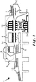
Figure 1 illustrates a platen press in which a platen cleaner according to an embodiment of the present invention can be used; -
Figure 2 illustrates a processing station of a platen press in more detail; -
Figures 3a, 3b and 3c show part of a platen cleaner according to an embodiment of the present invention respectively in a perspective, top and section view; -
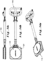
Figures 4a and 4b show a platen cleaner with handle according to an embodiment of the present invention respectively in a side and top view; -
Figures 5a and 5b show a handle of a platen cleaner in more detail respectively in a side and top view; -
Figures 6a, 6b and 6c illustrate a lift member of a platen cleaner according to an embodiment of the invention respectively in a top, perspective and section view; -
Figures 6d, 6e and 6f illustrate a frame of a platen cleaner according to an embodiment of the invention respectively in a top, perspective and side view; -
Figures 7a, 7b and 7c show a frame of a platen cleaner in more detail respectively in a perspective, top and side view; -
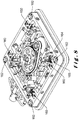
Figure 8 shows a frame with some parts of the lift member added to it in the foreseen relative positioning for a platen cleaner according to an embodiment of the present invention in a perspective view; -
Figures 9a, 9b and 9c show a lift member of a platen cleaner in more detail respectively in a perspective, top and side view; -
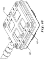
Figure 10 shows a frame with a frame support in a perspective view; -
Figure 11 shows a handle top part of a platen cleaner in a perspective view; -
Figures 12a and 12b show a telescopic handle support bar of a platen cleaner respectively in a perspective and top view; -
Figure 13 shows a safety part of a frame of a platen cleaner according to an embodiment of the invention; and -
Figures 14a, 14b and 14c show an assembled platen cleaner according to an embodiment of the invention respectively in a perspective, top and side view. -
Fig. 1 shows a machine for treating a plate element orsheet 7, more particular a platen press 1. The platen press comprises various stations: an infeed station 2, a cuttingstation 3, awaste stripping station 4 and adelivery station 6. The plate elements, i.e. the sheets of cardboard to be cut 7, are gripped and carried across the press 1 by a conveyor. - The conveyor is usually constituted by a gripping member, in the machine of
Fig. 1 a series of grippers mounted on atransverse gripper bar 8 that can be secured to gripper bar chains 9 (represented in dotted lines inFig. 1 ) driving the sheets to be cut 7 in the direction of Arrow F. Thegripper bar 8 grips the sheet to be cut 7 that is in a predetermined intermediate position, and the gripper bar chains 9 bring the sheets in a rated running into the successive processing stations. - The gripper bar chains 9 are carried and stopped periodically in a rated running so that, during a carrying each
gripper bar 8 with itssheet 7 is passed from an upstream station to the adjacent downstream station. The positions of the stops of the gripper bars 8 are imposed by a carrying of the gripper bar chains 9 over a constant distance. - Usually the
cutter station 3 comprises a lowermovable platen 11 to which are attached the cutting counter form, and an upper fixedplaten 12, having a lower face on which the cutting tool is attached, or conversely a lower fixed platen and an upper movable platen. Thecut sheet 13 is separated from thegripper bar 8 at thedelivery station 6, where thegripper bar 8 is still holding the front waste. Thedelivery station 6 is surmounted by aconveyor tape 14 intended to evacuate the front wastes of thecut sheets 13. Thecut sheets 13 are then discharged in a stack from the press 1. - Referring to
Fig. 2 , thecutter station 3 is described in more detail. The sheet to be cut 7 is carried by thegripper bar 8 between the fixedupper platen 12 and the vertically movablelower platen 11 of the platen press 1. In an alternative cutter station, theupper platen 12 may be movable or both may be movable. Once thesheet 7 is in position, the relative movement of thelower platen 11 and theupper platen 12 presses thesheet 7 in theblades 5 of theupper platen 12 such that thesheet 7 is die-cut in a size and shape defined by the pattern of theblades 5. Thelower platen 11 rests on abottom frame 17 by means of twoknuckles knuckle 36 and a lower half-knuckle 32. Theknuckles rod stock 14. -
Figs. 3a-3c show a device, i.e. aplaten cleaner 100 for cleaning the platen press 1 according to an embodiment of the invention. Theplaten cleaner 100 is used with thelower platen 11 in the open position. In this position, the height between thelower platen 11 andupper platen 12 is between 86mm to 198mm. Theplaten cleaner 100 comprises aframe 110, alift member 120 and arotating element 130. Theplaten cleaner 100 is arranged such that thelift member 120 can be moved vertically with respect to theframe 110 and therotating element 130 can rotate with respect to thelift member 120 and thus also with respect to theframe 110. - The
device 100 and theframe 110 comprise moving means for moving theframe 110 relative to the surface on which it is positioned. To do this, theframe 110 is provided with ball bearings, each ball bearing having asingle ball 112. When theframe 110 is laid on a surface, only theballs 112 are contacting the surface. Theballs 112 can rotate freely in the ball bearings allowing easy movement of theframe 110 and thus theplaten cleaner 100 over a surface. The overall height of theplaten cleaner 100 is smaller than the opening between thelower platen 11 and theupper platen 12 in their open position. In a preferred embodiment, the height of theplaten cleaner 100 is lower than 85mm. - Referring to
Figs. 6a-6e ,7a-7c and8 , theframe 110 comprises aframe body 170 with abase 172 and foursidewalls platen cleaner 100 comprises lifting means in the form of fourpneumatic cylinders 178 that are provided in the sidewalls. In the embodiment ofFigs. 6 to 8 , twopneumatic cylinders 178 are provided insidewall 174 and twopneumatic cylinders 178 are provided insidewall 176. In alternative embodiments, other configurations of thepneumatic cylinders 178 are possible. Eachpneumatic cylinder 178 has acylinder input 179 and uses the power of compressed gas to create a linear motion. The fourcylinder inputs 179 are connected by an internalpressure hose network 171 to a firstcompressed gas input 115. Thepneumatic cylinders 179 each have apiston rod 160 to transfer the force to thelift member 120. - The
frame 110 further comprises four guidingcylinders 180. The axis of each guidingcylinder 180 is positioned perpendicular to theframe base 172. The guidingcylinders 180 will guide guidingbars 162 of thelift member 120 during relative movement of thelift member 120 and theframe 110. - Referring to
Figs. 7a-7c and8 , the inside of the frame further comprises threeshafts 182 connected to the side walls of theframe body 170. On theshafts 182 are fourpinions 165 which can freely rotate around the shafts. Thepinions 165 are provided to come in contact with arack 164 of thelift member 120 during relative movement of thelift member 120 and theframe 110. The threeshafts 182 are positioned in a U-configuration on theframe body 170 and, where twoshafts 182 are forming a corner, bothshafts 182 have on their end abevel gear 183. - Thus, the lift system has four
pneumatic cylinders 179 withpiston rods 160 assembled in the four corner areas of theframe 110. Four guidingcylinders 180, also assembled in the corner areas of theframe 110, together with a synchronising mechanism ensure that the cleaning surface moves parallel to theframe 110. The synchronising mechanism comprises the fourracks 164 andpinions 165 in combination with the structure ofshafts 182 and bevel gears 183. - Referring to
Figs. 9a-9c , thelift member 120 in a platen cleaner according to an embodiment of the invention is illustrated in more detail. Thelift member 120 has in the corner areas the four guidingbars 162 corresponding to the positions of the guidingcylinders 180 in theframe body 170. Thelift member 120 further has 4holes 122 to receivescrews 190 to connect thelift member 120 to thepiston rods 160. Theracks 164 are positioned on thebase plate 195 of thelift member 120 to correspond with thepinions 165 of theframe 110. - The
lift member 120 further comprises the driving mechanism for rotating therotating element 130. Apneumatic oscillation cylinder 192 is provided on thebase plate 195 of thelift member 120 and a hose network is providing compressed gas towards thepneumatic oscillation cylinder 192. Acontrol valve 197 is controlling rotation to the right or to the left depending on which side of thecontrol valve 197 is providing compressed gas to thepneumatic oscillation cylinder 192. The oscillation angle is controlled by an oscillation angle setting 194. The oscillation angle is in the range 0-180º. - The
oscillation cylinder 192 is provided with cam switches 196. These cam switches 196 are switching thecontrol valve 197 causing to change the rotation direction of thepneumatic oscillation cylinder 192. By this continuously switching process,oscillation cylinder 192 is making continuously an oscillating movement as long as the compressed gas is provided to thepneumatic oscillation cylinder 192. The flow of compressed gas towards theoscillation cylinder 192 is controlled by an on/off switch on the handle as will be discussed in more detail below. - The driving mechanism further comprises a relatively
central bearing 199 for mounting therotating element 130. While the above discussed driving mechanism, guide bars 162,racks 164, etc. are assembled on one side of thebase plate 195, therotating element 130 is mounted to thebearing 199 on the other side of thebase plate 195. For this, thebase plate 195 has acentral opening 198. Thebearing 199 is also provided with agear wheel 191. Thegear wheel 191 is in his turn connected by abelt 193 with thepneumatic oscillation cylinder 192. In this way, the continuous oscillation movement of thecylinder 192 is transferred to thegear wheel 191, and thus to therotating element 130. A belt tensioner may be provided to control the belt tension for optimal power transmission. The belt transmission between thegear wheel 191 and thecylinder 192 may have a ratio of three. This ratio three transmission results in a decrease of the oscillation angle by a factor of three, but increases the cleaning force of therotating element 130 by the same factor. The cleaning force can further be controlled by the pressure of the compressed gas towards the lift system. A pressure control switch is provided on the handle to do so. This will be discussed in more detail below. - Referring to
Fig. 10 , the pneumatic lift system according to an embodiment of the invention has a maximum lift distance of 25mm. As mentioned above the height between thelower platen 11 and theupper platen 12 may vary between 86mm to 198mm which is much more than 25mm. Therefore, in an embodiment of the invention illustrated inFig. 10 , theplaten cleaner 100 is provided withframe support parts 167 mounted on theframe 110 on the side of the ball bearings and asupport frame 168 is mounted to theframe support parts 167. This increases the overall height of theplaten cleaner 100. Theframe support part 167 has similar ball bearings with each having a single ball. In the embodiment ofFig. 10 , theframe support part 167 has 6 ball bearings. In alternative embodiments there may be more or less. Theframe support parts 167 are typically provided in heights of 20, 40, 60, 80, 100 and 120mm, but other heights are possible as well. Thesupport frame 168 can also be assembled directly on theframe 110 withoutframe support parts 167. With theframe support parts 167 and thesupport frame 168, it's possible to use thesame platen cleaner 100 for platen presses 1 with a large variety of heights between thelower platen 11 and theupper platen 12. - The
rotating element 130 is provided with means to attach a cleaning material on therotating element 130. In an embodiment of the invention, therotating element 130 is provided with a hook-and-loop fastener, also called touch fastener. In that way a desired cleaning material can easily be provided on therotating element 130 and replaced by a new or different one with different cleaning properties. In a preferred embodiment therotating element 130 has a diameter of 300mm. - Referring to
Figs. 4a, 4b ,5a and 5b ,11 and12 a and b , theplaten cleaner 100 in an embodiment of the invention has ahandle 140 with atelescopic support bar 141. Theframe 110 has ahandle support 116 and thehandle 140 may be connected to thehandle support 116 by a snap connection. In alternative embodiments, alternative connections may be used, such as a connection with a shaft, bar or pin. Thetelescopic support bar 141 has a telescopic structure with multiple parts moving over each other. In the embodiment ofFigs. 4a and 4b , thetelescopic support bar 141 has four parts. In alternative embodiments, there can be more or less parts. The relative positioning of the sliding parts of thetelescopic support bar 141 is systematically locked and unlocked before and after a sliding in or out movement. This may for example be executed by an insert or a bolt-nut connection. - In the embodiment of
Fig. 4 however this is executed by rotation of aknurled nut 143 on the larger bar of the two bars which slid with respect to each other. Rotating theknurled nut 143 such that thenut 143 is moving more on the larger bar fixes the bars relative to each other. Rotating theknurled nut 143 on the large bar such that the nut is moving towards the end of the larger bar, releases the bars relative to each other. Sliding the parts of the telescopic bar out of each other will make thehandle 140 longer, sliding them back in each other will make thehandle 140 again shorter. In this way thehandle 140 can be customised during executing the cleaning action to operate always with the perfect length of thehandle 140. A further advantage of thetelescopic bar 141 is that the size for transporting is smaller. - The
handle 140 is shown in isolation inFigs. 5a and 5b . On both sides of thetelescopic support bar 141 are twocompressed gas connectors compressed gas connector 142 withcompressed gas connector 146. The second compressed gas hose is connectingcompressed gas connector 144 withcompressed gas connector 148. - The first and second compressed gas hoses are constructed such that they enlarge when the telescopic bars are slid out of each other and the length of the compressed gas hoses shortens again when the telescopic bars are slid in each other. This is realised by providing the compressed gas hoses shaped as a spiral over the length of the telescopic bars when slid in. In that way, the spiral shaped compressed gas hoses can elongate as the telescopic bars are slid out. In an alternative embodiment the compressed gas hoses may not be provided in the bars but simply guided outside the telescopic support bar towards the
frame 110 of theplaten cleaner 100. - With reference to
Figs. 11 and12 , thehandle 140 may have aseparable handle top 145 which provides control functionality to the user and which connects to asupport bar 141. In alternative embodiments thehandle top 145 and thehandle support bar 141 may be not separable. Thehandle top 145 provides control of the lift system as well as the driving mechanism. The control of the driving mechanism is indicated on thehandle top 145 by abended arrow 147 referring to the rotational movement. The control of the lift system is indicated on thehandle top 145 by astraight arrow 149 referring to the translation movement. - The compressed gas hose circuits for the lift system and driving mechanism are further also completely separated and both hose circuits has their own colour code, for example black for the hose circuit of the lift system and blue for the hose circuit of the driving system. Both hose circuits are further provided with a pressure controller or
regulator - In the embodiment of
Fig. 11 , with apressure regulator lift systems 157 controls the pressure of therotating element 130 perpendicular on the cleaning surface. The pressure regulator of thedriving mechanism 159 controls the rotation force of therotating element 130 in the contact plane between therotating element 130 and the cleaning surface. - Next to each
pressure regulator switches handle top 145 is further provided with a maincompressed gas input 161. In a preferred embodiment, the compressed gas is compressed air. Via an internal hose network in thehandle top 145, the input compressed gas is guided from themain input 161 to two compressedgas output connectors - Referring to
Figs. 13 and14 , in an embodiment of the invention theplaten cleaner 100 may have askirt 210 mountable on thelift member 120. The main part of the skirt is made by a bended metal plate to form a shape corresponding to the outside walls of thelift member 120. By having this shape, theskirt 210 can be moved partly over the side of thebase plate 195 of thelift member 120. Theskirt 210 is fixed to thelift member 120 by providingscrews 212 throughholes 214 in theskirt 210 corresponding to holes 215 in thebase plate 195. Theholes 216 in thebase plate 195 are visible inFig. 9 . Theskirt 210 further has an L-part. The L-part is mainly made of rubber and is connected to the main part of the skirt by screws. At the position of the screws, a small plate is positioned between the screws and the rubber to avoid that the screws are damaging the rubber. The other side of the L-part is connected to thehandle support 116 of theframe 110. The connection between the L-part and thehandle support 116 is also by screws and a small plate to avoid damaging the rubber. The rubber L-part is stretched maximal when thelift member 120 is moved maximal relative to theframe 110. When thelift member 120 is moving back towards its start position, the rubber L-part is de-stretching towards its initial size and shape. Theskirt 210 is provided to avoid that dirt of the cleaning is moving into the mechanism of thedevice 100. - Furthermore, the various embodiments, although referred to as preferred are to be construed as exemplary manners in which the invention may be implemented rather than as limiting the scope of the invention.
Claims (21)
- A device for cleaning a platen of a processing platen press (1), the processing platen press (1) comprising a lower and an upper platen (11, 12) of which at least one is movable towards the other and wherein at least one is arranged to allow tools to process a plate element (7) fed between the lower and the upper platen (11, 12), comprising:- a frame (110) having a base (172) defining a base plane substantially parallel to a surface on which the frame (110) is positioned,- a lift member (120) arranged to the frame (110) such that a relative movement can be executed between the frame (110) and the lift member (120) in a direction substantially perpendicular to the base plane,- lifting means (178) for moving the frame (110) relative to the lift member (120), and- a rotating element (130) arranged on the lift member (120) and configured to rotate around an axis substantially parallel to the direction of relative movement between the frame (110) and the lift member (120),characterised in that the lifting means (178) are pneumatic lifting means configured to press the rotating element (130) against the platen (11, 12) to be cleaned with a predetermined pressure.
- The device according to claim 1, adapted to be used in a first configuration in which the device is arranged to clean the upper platen of the platen press and in a second configuration in which the device is rotated by 180 degrees relative to the first configuration in which the device is arranged to clean the lower platen of the platen press.
- The device according to claim 1 or claim 2, wherein the frame (110) comprises moving means for moving the frame (110) relative to the surface on which it is positioned, the moving means preferably comprising one or more ball bearings.
- The device according to any preceding claim, wherein said moving means are at least three ball bearings with a single ball (112) arranged in the frame (110) such that only the balls (112) contact the surface against which they are positioned.
- The device according to any one of the preceding claims, wherein it further comprises pneumatic rotating means (192) for rotating the rotating element (130).
- The device according to claim 5, wherein the pneumatic rotating means (192) is arranged to rotate the rotating element (130) in an oscillation movement.
- The device according to any one of the preceding claims, wherein it further comprises a handle (140) connected to the frame (110) for moving the frame (110) relative to the lower or upper platen (11, 12).
- The device according to claim 7, wherein the handle (140) comprises a hollow bar (141) for guiding compressed gas towards the frame (110).
- The device according to claim 8, wherein the bar (141) is a telescopic bar, the device further comprising first and second compressed gas hoses arranged to enlarge when the telescopic bars are slid out of each other and to shorten when the telescopic bars are slid in each other.
- The device according to any one of claims 7 to 9, wherein the handle (140) comprises control means for controlling the lifting means (178), the rotating means (192) or both.
- The device according to claim 10, wherein the control means comprises a first display element (156) for displaying the pressure of the compressed gas for the lifting means (178).
- The device according to claims 10 or 11, wherein the control means comprises a first controller to control the pressure of the compressed gas for the lifting means (178).
- The device according to claim 10, wherein the control means comprises a second display element (159) for displaying the pressure of the rotating means (192).
- The device according to claim 10 or 13, wherein the control means comprises a second controller to control the pressure of the compressed gas for the rotating means (192).
- The device according to any preceding claim, wherein the rotating element (130) comprises means to attach a cleaning material, preferably a hook-and-loop or touch fastener.
- The device according to any preceding claim, being further arranged to receive a support frame 168 to increase the overall height of the platen cleaner (100).
- A platen cleaning kit comprising a device for cleaning a platen according to any preceding claim and one or more support frames (168) adapted to be attached to the device and arranged to increase the overall height of the platen cleaner (100).
- A platen cleaning kit according to claim 17, wherein the one or more support frames (168) comprises movement means, preferably one ore more ball bearings, arranged to allow the support frame (168) to slide over a surface against which it is positioned.
- A method for cleaning a platen (11, 12) in a processing platen press (1) using the device for cleaning (100) or the platen cleaning kit according to any one of the preceding claims, the method comprises the steps consisting in:- positioning the device (100) between the upper and lower platen (11, 12) of the platen press (1) with the rotating element (130) facing the platen to be cleaned;- pneumatically increasing the distance between the rotating element (130) and frame (110) such that the rotating element (130) is pressed against the platen (11, 12) to be cleaned with a predetermined pressure.- rotating the rotating element with respect to the platen (11, 12) to be cleaned; and- moving the device (100) over the platen (11, 12) to be cleaned.
- The method according to claim 19, wherein it further comprises the step of providing a cleaning product on the platen (11, 12) to be cleaned.
- The method according to claim 19 or 20, wherein it further comprises the step of adding or removing a support frame (168) to increase or decrease the overall height of the platen cleaner (100).
Applications Claiming Priority (2)
| Application Number | Priority Date | Filing Date | Title |
|---|---|---|---|
| EP14000694 | 2014-02-27 | ||
| PCT/EP2015/025009 WO2015128096A1 (en) | 2014-02-27 | 2015-02-25 | Cleaning device for a processing platen press |
Publications (2)
| Publication Number | Publication Date |
|---|---|
| EP3110570A1 EP3110570A1 (en) | 2017-01-04 |
| EP3110570B1 true EP3110570B1 (en) | 2021-07-28 |
Family
ID=50190151
Family Applications (1)
| Application Number | Title | Priority Date | Filing Date |
|---|---|---|---|
| EP15708122.5A Active EP3110570B1 (en) | 2014-02-27 | 2015-02-25 | Cleaning device for a processing platen press |
Country Status (5)
| Country | Link |
|---|---|
| US (1) | US10391522B2 (en) |
| EP (1) | EP3110570B1 (en) |
| CN (1) | CN106232246B (en) |
| ES (1) | ES2886028T3 (en) |
| WO (1) | WO2015128096A1 (en) |
Families Citing this family (3)
| Publication number | Priority date | Publication date | Assignee | Title |
|---|---|---|---|---|
| US20210316373A1 (en) * | 2018-10-10 | 2021-10-14 | Ls Flexo Aps | An apparatus for working opposite arranged surfaces |
| CN111604781B (en) * | 2020-06-03 | 2021-06-01 | 南通理工学院 | A napping device that is used for steel construction application to have a dust removal function |
| WO2025026514A1 (en) * | 2023-07-30 | 2025-02-06 | Ls Flexo Aps | Rotating polishing device |
Family Cites Families (11)
| Publication number | Priority date | Publication date | Assignee | Title |
|---|---|---|---|---|
| US2722090A (en) * | 1954-01-21 | 1955-11-01 | Goodrich Co B F | Abrading apparatus for mold platens |
| US4546574A (en) | 1984-05-03 | 1985-10-15 | Armstrong World Industries, Inc. | Press cleaning apparatus |
| JP2660248B2 (en) * | 1988-01-06 | 1997-10-08 | 株式会社 半導体エネルギー研究所 | Film formation method using light |
| US5176075A (en) | 1989-02-16 | 1993-01-05 | Iberica A.G., S.A. | Machines for handling or working materials in laminar or sheet form |
| CN2066358U (en) * | 1990-02-24 | 1990-11-28 | 骆汉平 | Multifuncitonal hydrodynamic cleaner |
| DE19819640A1 (en) * | 1998-05-05 | 1999-11-18 | Wilhelm Busch | High pressure cleaning appliance with rotating brush |
| FR2782027B1 (en) | 1998-08-06 | 2000-10-27 | Economie Mixte Des Transports | DEVICE FOR IN SITU RECTIFICATION OF BRAKE DISCS OF RAILWAY CARS, ESPECIALLY METROPOLITAN |
| US6705930B2 (en) * | 2000-01-28 | 2004-03-16 | Lam Research Corporation | System and method for polishing and planarizing semiconductor wafers using reduced surface area polishing pads and variable partial pad-wafer overlapping techniques |
| US20020129835A1 (en) * | 2000-12-21 | 2002-09-19 | The Procter & Gambie Company | Motorized hand-held scrubbing device, a disposable scrubbing surface, and a method of use therefor |
| CN102300794B (en) | 2009-02-02 | 2015-05-20 | 鲍勃斯脱股份有限公司 | Device for positioning a plate element in an insertion station of a processing machine |
| US20100215471A1 (en) * | 2009-02-24 | 2010-08-26 | Younce Sr Matthew R | Radio base station lifting machine |
-
2015
- 2015-02-25 WO PCT/EP2015/025009 patent/WO2015128096A1/en not_active Ceased
- 2015-02-25 EP EP15708122.5A patent/EP3110570B1/en active Active
- 2015-02-25 CN CN201580020792.1A patent/CN106232246B/en active Active
- 2015-02-25 ES ES15708122T patent/ES2886028T3/en active Active
- 2015-02-25 US US15/121,906 patent/US10391522B2/en active Active
Also Published As
| Publication number | Publication date |
|---|---|
| EP3110570A1 (en) | 2017-01-04 |
| WO2015128096A1 (en) | 2015-09-03 |
| CN106232246B (en) | 2019-11-12 |
| ES2886028T3 (en) | 2021-12-16 |
| CN106232246A (en) | 2016-12-14 |
| US10391522B2 (en) | 2019-08-27 |
| US20170014870A1 (en) | 2017-01-19 |
Similar Documents
| Publication | Publication Date | Title |
|---|---|---|
| KR101809807B1 (en) | Method for adjusting the radial gap between two tools, arrangement for transforming a support, cassette, unit and machine equipped with same | |
| US10391522B2 (en) | Cleaning device for a processing platen press | |
| KR20160075281A (en) | Paper forming machine for variable paper type | |
| US8079587B2 (en) | Sheet braking mechanism | |
| DE202013104432U1 (en) | Machine for folding and gluing blanks for the production of folding cartons | |
| US8230989B2 (en) | Shuttle machine for machine tool | |
| JP2025122250A (en) | Conveyor belt formed by multiple bristle brushes | |
| ITTO20110931A1 (en) | MACHINE TO CARRY OUT CUTTING OPERATIONS ON LAMINATED GLASS SHEETS | |
| EP3762232B1 (en) | Advance-shaft transition apparatus and hot foil stamping and die-cutting equipment | |
| KR102400943B1 (en) | Blowing means unit and hot foil stamping and die-cutting device | |
| ITUD20080197A1 (en) | EQUIPMENT FOR THE LOADING OF A RELATIVELY RIGID MATERIAL, EXAMPLE CARDBOARD, AND ITS RELEASE PROCEDURE | |
| JP2004066462A (en) | Mold replacing device | |
| CN102528853B (en) | Processing station for die-cutting machine | |
| KR102151950B1 (en) | Surface cutting device of Aluminum Disposable | |
| JP6704313B2 (en) | Trimming device | |
| EP3238917A1 (en) | Clamping devices for clamping die members onto web packaging machines | |
| KR101534447B1 (en) | Chamfering device | |
| CN113385576B (en) | Machining of machine parts is with section arc punching machine | |
| CN224116869U (en) | Automatic switching cover membrane structure is rolled up to two membranes | |
| CN215698377U (en) | Aluminum plate side cut device | |
| KR102027247B1 (en) | Up and Down Apparatus for Dieboard of Large Size Automatic Die Cutting Machine | |
| IT202400000576A1 (en) | A LINE AND A METHOD FOR THE AUTOMATED PRODUCTION OF CARDBOARD BOXES | |
| KR20030075138A (en) | Auto dispersing load apparatus of a building panel | |
| JP2001347490A (en) | Wood pattern retaining mechanism for plate punching machine | |
| KR20170014969A (en) | Box Making Machine |
Legal Events
| Date | Code | Title | Description |
|---|---|---|---|
| PUAI | Public reference made under article 153(3) epc to a published international application that has entered the european phase |
Free format text: ORIGINAL CODE: 0009012 |
|
| STAA | Information on the status of an ep patent application or granted ep patent |
Free format text: STATUS: REQUEST FOR EXAMINATION WAS MADE |
|
| 17P | Request for examination filed |
Effective date: 20160916 |
|
| AK | Designated contracting states |
Kind code of ref document: A1 Designated state(s): AL AT BE BG CH CY CZ DE DK EE ES FI FR GB GR HR HU IE IS IT LI LT LU LV MC MK MT NL NO PL PT RO RS SE SI SK SM TR |
|
| AX | Request for extension of the european patent |
Extension state: BA ME |
|
| DAX | Request for extension of the european patent (deleted) | ||
| GRAP | Despatch of communication of intention to grant a patent |
Free format text: ORIGINAL CODE: EPIDOSNIGR1 |
|
| STAA | Information on the status of an ep patent application or granted ep patent |
Free format text: STATUS: GRANT OF PATENT IS INTENDED |
|
| RIC1 | Information provided on ipc code assigned before grant |
Ipc: B08B 1/04 20060101AFI20210326BHEP |
|
| INTG | Intention to grant announced |
Effective date: 20210430 |
|
| GRAS | Grant fee paid |
Free format text: ORIGINAL CODE: EPIDOSNIGR3 |
|
| GRAA | (expected) grant |
Free format text: ORIGINAL CODE: 0009210 |
|
| STAA | Information on the status of an ep patent application or granted ep patent |
Free format text: STATUS: THE PATENT HAS BEEN GRANTED |
|
| AK | Designated contracting states |
Kind code of ref document: B1 Designated state(s): AL AT BE BG CH CY CZ DE DK EE ES FI FR GB GR HR HU IE IS IT LI LT LU LV MC MK MT NL NO PL PT RO RS SE SI SK SM TR |
|
| REG | Reference to a national code |
Ref country code: GB Ref legal event code: FG4D |
|
| REG | Reference to a national code |
Ref country code: CH Ref legal event code: EP |
|
| REG | Reference to a national code |
Ref country code: DE Ref legal event code: R096 Ref document number: 602015071672 Country of ref document: DE |
|
| REG | Reference to a national code |
Ref country code: AT Ref legal event code: REF Ref document number: 1414245 Country of ref document: AT Kind code of ref document: T Effective date: 20210815 |
|
| REG | Reference to a national code |
Ref country code: IE Ref legal event code: FG4D |
|
| REG | Reference to a national code |
Ref country code: LT Ref legal event code: MG9D |
|
| REG | Reference to a national code |
Ref country code: NL Ref legal event code: MP Effective date: 20210728 |
|
| REG | Reference to a national code |
Ref country code: AT Ref legal event code: MK05 Ref document number: 1414245 Country of ref document: AT Kind code of ref document: T Effective date: 20210728 |
|
| REG | Reference to a national code |
Ref country code: ES Ref legal event code: FG2A Ref document number: 2886028 Country of ref document: ES Kind code of ref document: T3 Effective date: 20211216 |
|
| PG25 | Lapsed in a contracting state [announced via postgrant information from national office to epo] |
Ref country code: RS Free format text: LAPSE BECAUSE OF FAILURE TO SUBMIT A TRANSLATION OF THE DESCRIPTION OR TO PAY THE FEE WITHIN THE PRESCRIBED TIME-LIMIT Effective date: 20210728 Ref country code: SE Free format text: LAPSE BECAUSE OF FAILURE TO SUBMIT A TRANSLATION OF THE DESCRIPTION OR TO PAY THE FEE WITHIN THE PRESCRIBED TIME-LIMIT Effective date: 20210728 Ref country code: HR Free format text: LAPSE BECAUSE OF FAILURE TO SUBMIT A TRANSLATION OF THE DESCRIPTION OR TO PAY THE FEE WITHIN THE PRESCRIBED TIME-LIMIT Effective date: 20210728 Ref country code: NO Free format text: LAPSE BECAUSE OF FAILURE TO SUBMIT A TRANSLATION OF THE DESCRIPTION OR TO PAY THE FEE WITHIN THE PRESCRIBED TIME-LIMIT Effective date: 20211028 Ref country code: NL Free format text: LAPSE BECAUSE OF FAILURE TO SUBMIT A TRANSLATION OF THE DESCRIPTION OR TO PAY THE FEE WITHIN THE PRESCRIBED TIME-LIMIT Effective date: 20210728 Ref country code: PT Free format text: LAPSE BECAUSE OF FAILURE TO SUBMIT A TRANSLATION OF THE DESCRIPTION OR TO PAY THE FEE WITHIN THE PRESCRIBED TIME-LIMIT Effective date: 20211129 Ref country code: FI Free format text: LAPSE BECAUSE OF FAILURE TO SUBMIT A TRANSLATION OF THE DESCRIPTION OR TO PAY THE FEE WITHIN THE PRESCRIBED TIME-LIMIT Effective date: 20210728 Ref country code: AT Free format text: LAPSE BECAUSE OF FAILURE TO SUBMIT A TRANSLATION OF THE DESCRIPTION OR TO PAY THE FEE WITHIN THE PRESCRIBED TIME-LIMIT Effective date: 20210728 Ref country code: BG Free format text: LAPSE BECAUSE OF FAILURE TO SUBMIT A TRANSLATION OF THE DESCRIPTION OR TO PAY THE FEE WITHIN THE PRESCRIBED TIME-LIMIT Effective date: 20211028 Ref country code: LT Free format text: LAPSE BECAUSE OF FAILURE TO SUBMIT A TRANSLATION OF THE DESCRIPTION OR TO PAY THE FEE WITHIN THE PRESCRIBED TIME-LIMIT Effective date: 20210728 |
|
| PG25 | Lapsed in a contracting state [announced via postgrant information from national office to epo] |
Ref country code: PL Free format text: LAPSE BECAUSE OF FAILURE TO SUBMIT A TRANSLATION OF THE DESCRIPTION OR TO PAY THE FEE WITHIN THE PRESCRIBED TIME-LIMIT Effective date: 20210728 Ref country code: LV Free format text: LAPSE BECAUSE OF FAILURE TO SUBMIT A TRANSLATION OF THE DESCRIPTION OR TO PAY THE FEE WITHIN THE PRESCRIBED TIME-LIMIT Effective date: 20210728 Ref country code: GR Free format text: LAPSE BECAUSE OF FAILURE TO SUBMIT A TRANSLATION OF THE DESCRIPTION OR TO PAY THE FEE WITHIN THE PRESCRIBED TIME-LIMIT Effective date: 20211029 |
|
| PG25 | Lapsed in a contracting state [announced via postgrant information from national office to epo] |
Ref country code: DK Free format text: LAPSE BECAUSE OF FAILURE TO SUBMIT A TRANSLATION OF THE DESCRIPTION OR TO PAY THE FEE WITHIN THE PRESCRIBED TIME-LIMIT Effective date: 20210728 |
|
| REG | Reference to a national code |
Ref country code: DE Ref legal event code: R097 Ref document number: 602015071672 Country of ref document: DE |
|
| PG25 | Lapsed in a contracting state [announced via postgrant information from national office to epo] |
Ref country code: SM Free format text: LAPSE BECAUSE OF FAILURE TO SUBMIT A TRANSLATION OF THE DESCRIPTION OR TO PAY THE FEE WITHIN THE PRESCRIBED TIME-LIMIT Effective date: 20210728 Ref country code: SK Free format text: LAPSE BECAUSE OF FAILURE TO SUBMIT A TRANSLATION OF THE DESCRIPTION OR TO PAY THE FEE WITHIN THE PRESCRIBED TIME-LIMIT Effective date: 20210728 Ref country code: RO Free format text: LAPSE BECAUSE OF FAILURE TO SUBMIT A TRANSLATION OF THE DESCRIPTION OR TO PAY THE FEE WITHIN THE PRESCRIBED TIME-LIMIT Effective date: 20210728 Ref country code: EE Free format text: LAPSE BECAUSE OF FAILURE TO SUBMIT A TRANSLATION OF THE DESCRIPTION OR TO PAY THE FEE WITHIN THE PRESCRIBED TIME-LIMIT Effective date: 20210728 Ref country code: CZ Free format text: LAPSE BECAUSE OF FAILURE TO SUBMIT A TRANSLATION OF THE DESCRIPTION OR TO PAY THE FEE WITHIN THE PRESCRIBED TIME-LIMIT Effective date: 20210728 Ref country code: AL Free format text: LAPSE BECAUSE OF FAILURE TO SUBMIT A TRANSLATION OF THE DESCRIPTION OR TO PAY THE FEE WITHIN THE PRESCRIBED TIME-LIMIT Effective date: 20210728 |
|
| PLBE | No opposition filed within time limit |
Free format text: ORIGINAL CODE: 0009261 |
|
| STAA | Information on the status of an ep patent application or granted ep patent |
Free format text: STATUS: NO OPPOSITION FILED WITHIN TIME LIMIT |
|
| 26N | No opposition filed |
Effective date: 20220429 |
|
| PG25 | Lapsed in a contracting state [announced via postgrant information from national office to epo] |
Ref country code: MC Free format text: LAPSE BECAUSE OF FAILURE TO SUBMIT A TRANSLATION OF THE DESCRIPTION OR TO PAY THE FEE WITHIN THE PRESCRIBED TIME-LIMIT Effective date: 20210728 |
|
| REG | Reference to a national code |
Ref country code: BE Ref legal event code: MM Effective date: 20220228 |
|
| PG25 | Lapsed in a contracting state [announced via postgrant information from national office to epo] |
Ref country code: LU Free format text: LAPSE BECAUSE OF NON-PAYMENT OF DUE FEES Effective date: 20220225 |
|
| PG25 | Lapsed in a contracting state [announced via postgrant information from national office to epo] |
Ref country code: IE Free format text: LAPSE BECAUSE OF NON-PAYMENT OF DUE FEES Effective date: 20220225 |
|
| PG25 | Lapsed in a contracting state [announced via postgrant information from national office to epo] |
Ref country code: BE Free format text: LAPSE BECAUSE OF NON-PAYMENT OF DUE FEES Effective date: 20220228 |
|
| REG | Reference to a national code |
Ref country code: DE Ref legal event code: R079 Ref document number: 602015071672 Country of ref document: DE Free format text: PREVIOUS MAIN CLASS: B08B0001040000 Ipc: B08B0001320000 |
|
| PG25 | Lapsed in a contracting state [announced via postgrant information from national office to epo] |
Ref country code: HU Free format text: LAPSE BECAUSE OF FAILURE TO SUBMIT A TRANSLATION OF THE DESCRIPTION OR TO PAY THE FEE WITHIN THE PRESCRIBED TIME-LIMIT; INVALID AB INITIO Effective date: 20150225 |
|
| PG25 | Lapsed in a contracting state [announced via postgrant information from national office to epo] |
Ref country code: MK Free format text: LAPSE BECAUSE OF FAILURE TO SUBMIT A TRANSLATION OF THE DESCRIPTION OR TO PAY THE FEE WITHIN THE PRESCRIBED TIME-LIMIT Effective date: 20210728 Ref country code: CY Free format text: LAPSE BECAUSE OF FAILURE TO SUBMIT A TRANSLATION OF THE DESCRIPTION OR TO PAY THE FEE WITHIN THE PRESCRIBED TIME-LIMIT Effective date: 20210728 |
|
| PG25 | Lapsed in a contracting state [announced via postgrant information from national office to epo] |
Ref country code: TR Free format text: LAPSE BECAUSE OF FAILURE TO SUBMIT A TRANSLATION OF THE DESCRIPTION OR TO PAY THE FEE WITHIN THE PRESCRIBED TIME-LIMIT Effective date: 20210728 |
|
| PG25 | Lapsed in a contracting state [announced via postgrant information from national office to epo] |
Ref country code: MT Free format text: LAPSE BECAUSE OF FAILURE TO SUBMIT A TRANSLATION OF THE DESCRIPTION OR TO PAY THE FEE WITHIN THE PRESCRIBED TIME-LIMIT Effective date: 20210728 |
|
| PGFP | Annual fee paid to national office [announced via postgrant information from national office to epo] |
Ref country code: ES Payment date: 20250305 Year of fee payment: 11 |
|
| REG | Reference to a national code |
Ref country code: CH Ref legal event code: U11 Free format text: ST27 STATUS EVENT CODE: U-0-0-U10-U11 (AS PROVIDED BY THE NATIONAL OFFICE) Effective date: 20260301 |
|
| PGFP | Annual fee paid to national office [announced via postgrant information from national office to epo] |
Ref country code: GB Payment date: 20260219 Year of fee payment: 12 |
|
| PGFP | Annual fee paid to national office [announced via postgrant information from national office to epo] |
Ref country code: DE Payment date: 20260218 Year of fee payment: 12 |
|
| PGFP | Annual fee paid to national office [announced via postgrant information from national office to epo] |
Ref country code: IT Payment date: 20260224 Year of fee payment: 12 |
|
| PGFP | Annual fee paid to national office [announced via postgrant information from national office to epo] |
Ref country code: FR Payment date: 20260218 Year of fee payment: 12 |
|
| PGFP | Annual fee paid to national office [announced via postgrant information from national office to epo] |
Ref country code: CH Payment date: 20260301 Year of fee payment: 12 |