EP3109999A2 - Method and device for determining a physical variable of a multi-phase synchronous machine - Google Patents
Method and device for determining a physical variable of a multi-phase synchronous machine Download PDFInfo
- Publication number
- EP3109999A2 EP3109999A2 EP16175377.7A EP16175377A EP3109999A2 EP 3109999 A2 EP3109999 A2 EP 3109999A2 EP 16175377 A EP16175377 A EP 16175377A EP 3109999 A2 EP3109999 A2 EP 3109999A2
- Authority
- EP
- European Patent Office
- Prior art keywords
- phase
- current
- state variable
- phase currents
- synchronous machine
- Prior art date
- Legal status (The legal status is an assumption and is not a legal conclusion. Google has not performed a legal analysis and makes no representation as to the accuracy of the status listed.)
- Granted
Links
- 230000001360 synchronised effect Effects 0.000 title claims abstract description 41
- 238000000034 method Methods 0.000 title claims description 15
- 238000004364 calculation method Methods 0.000 claims description 41
- 238000012544 monitoring process Methods 0.000 claims description 20
- 230000001960 triggered effect Effects 0.000 claims description 5
- 230000009466 transformation Effects 0.000 description 15
- 230000000875 corresponding effect Effects 0.000 description 9
- 238000004804 winding Methods 0.000 description 8
- 230000006378 damage Effects 0.000 description 5
- 238000001514 detection method Methods 0.000 description 5
- 230000009471 action Effects 0.000 description 3
- 230000002950 deficient Effects 0.000 description 3
- 230000035508 accumulation Effects 0.000 description 2
- 238000009825 accumulation Methods 0.000 description 2
- 230000015572 biosynthetic process Effects 0.000 description 2
- 230000008859 change Effects 0.000 description 2
- 238000004519 manufacturing process Methods 0.000 description 2
- 230000007935 neutral effect Effects 0.000 description 2
- 238000012545 processing Methods 0.000 description 2
- 238000012546 transfer Methods 0.000 description 2
- 208000027418 Wounds and injury Diseases 0.000 description 1
- 230000004913 activation Effects 0.000 description 1
- 230000001276 controlling effect Effects 0.000 description 1
- 238000013461 design Methods 0.000 description 1
- 230000005611 electricity Effects 0.000 description 1
- 238000005516 engineering process Methods 0.000 description 1
- 238000011156 evaluation Methods 0.000 description 1
- 230000004907 flux Effects 0.000 description 1
- 208000014674 injury Diseases 0.000 description 1
- 238000005259 measurement Methods 0.000 description 1
- 230000003287 optical effect Effects 0.000 description 1
- 230000008569 process Effects 0.000 description 1
- 238000000844 transformation Methods 0.000 description 1
- 238000012795 verification Methods 0.000 description 1
Images


Classifications
-
- H—ELECTRICITY
- H02—GENERATION; CONVERSION OR DISTRIBUTION OF ELECTRIC POWER
- H02P—CONTROL OR REGULATION OF ELECTRIC MOTORS, ELECTRIC GENERATORS OR DYNAMO-ELECTRIC CONVERTERS; CONTROLLING TRANSFORMERS, REACTORS OR CHOKE COILS
- H02P29/00—Arrangements for regulating or controlling electric motors, appropriate for both AC and DC motors
- H02P29/02—Providing protection against overload without automatic interruption of supply
-
- G—PHYSICS
- G01—MEASURING; TESTING
- G01R—MEASURING ELECTRIC VARIABLES; MEASURING MAGNETIC VARIABLES
- G01R31/00—Arrangements for testing electric properties; Arrangements for locating electric faults; Arrangements for electrical testing characterised by what is being tested not provided for elsewhere
- G01R31/34—Testing dynamo-electric machines
-
- H—ELECTRICITY
- H02—GENERATION; CONVERSION OR DISTRIBUTION OF ELECTRIC POWER
- H02P—CONTROL OR REGULATION OF ELECTRIC MOTORS, ELECTRIC GENERATORS OR DYNAMO-ELECTRIC CONVERTERS; CONTROLLING TRANSFORMERS, REACTORS OR CHOKE COILS
- H02P23/00—Arrangements or methods for the control of AC motors characterised by a control method other than vector control
- H02P23/14—Estimation or adaptation of motor parameters, e.g. rotor time constant, flux, speed, current or voltage
-
- H—ELECTRICITY
- H02—GENERATION; CONVERSION OR DISTRIBUTION OF ELECTRIC POWER
- H02P—CONTROL OR REGULATION OF ELECTRIC MOTORS, ELECTRIC GENERATORS OR DYNAMO-ELECTRIC CONVERTERS; CONTROLLING TRANSFORMERS, REACTORS OR CHOKE COILS
- H02P29/00—Arrangements for regulating or controlling electric motors, appropriate for both AC and DC motors
- H02P29/02—Providing protection against overload without automatic interruption of supply
- H02P29/024—Detecting a fault condition, e.g. short circuit, locked rotor, open circuit or loss of load
- H02P29/0241—Detecting a fault condition, e.g. short circuit, locked rotor, open circuit or loss of load the fault being an overvoltage
-
- H—ELECTRICITY
- H02—GENERATION; CONVERSION OR DISTRIBUTION OF ELECTRIC POWER
- H02P—CONTROL OR REGULATION OF ELECTRIC MOTORS, ELECTRIC GENERATORS OR DYNAMO-ELECTRIC CONVERTERS; CONTROLLING TRANSFORMERS, REACTORS OR CHOKE COILS
- H02P29/00—Arrangements for regulating or controlling electric motors, appropriate for both AC and DC motors
- H02P29/02—Providing protection against overload without automatic interruption of supply
- H02P29/024—Detecting a fault condition, e.g. short circuit, locked rotor, open circuit or loss of load
- H02P29/027—Detecting a fault condition, e.g. short circuit, locked rotor, open circuit or loss of load the fault being an over-current
-
- H—ELECTRICITY
- H02—GENERATION; CONVERSION OR DISTRIBUTION OF ELECTRIC POWER
- H02P—CONTROL OR REGULATION OF ELECTRIC MOTORS, ELECTRIC GENERATORS OR DYNAMO-ELECTRIC CONVERTERS; CONTROLLING TRANSFORMERS, REACTORS OR CHOKE COILS
- H02P29/00—Arrangements for regulating or controlling electric motors, appropriate for both AC and DC motors
- H02P29/02—Providing protection against overload without automatic interruption of supply
- H02P29/032—Preventing damage to the motor, e.g. setting individual current limits for different drive conditions
-
- H—ELECTRICITY
- H02—GENERATION; CONVERSION OR DISTRIBUTION OF ELECTRIC POWER
- H02P—CONTROL OR REGULATION OF ELECTRIC MOTORS, ELECTRIC GENERATORS OR DYNAMO-ELECTRIC CONVERTERS; CONTROLLING TRANSFORMERS, REACTORS OR CHOKE COILS
- H02P31/00—Arrangements for regulating or controlling electric motors not provided for in groups H02P1/00 - H02P5/00, H02P7/00 or H02P21/00 - H02P29/00
-
- H—ELECTRICITY
- H02—GENERATION; CONVERSION OR DISTRIBUTION OF ELECTRIC POWER
- H02P—CONTROL OR REGULATION OF ELECTRIC MOTORS, ELECTRIC GENERATORS OR DYNAMO-ELECTRIC CONVERTERS; CONTROLLING TRANSFORMERS, REACTORS OR CHOKE COILS
- H02P6/00—Arrangements for controlling synchronous motors or other dynamo-electric motors using electronic commutation dependent on the rotor position; Electronic commutators therefor
- H02P6/12—Monitoring commutation; Providing indication of commutation failure
Definitions
- the invention relates to a method and a device for the reliable determination of a state variable of a three-phase synchronous machine, which is supplied with electric current by a multi-phase current network with n ⁇ 3 phases, wherein current values of at least n-1 phase currents from at least n-1 phases of a multi-phase current network are detected and by means of the at least n-1 first current current values, a state variable is calculated. Furthermore, the invention relates to the use of the method for safe operation of a three-phase synchronous machine.
- the task of a SLT function is to prevent an electric drive from exceeding a set value or a defined torque, or when using a linear motor, a defined force.
- the current torque of the electric motor, or the current force in the case of a linear motor, or a torque at another point of the drive is monitored by the SLT function in the rule.
- a torque of the electric drive is often mentioned as a result, the statements also apply analogously to the force of a linear motor.
- an allowable value of the torque of the electric drive is not exceeded, there is a certain safety function, for example, when foreign objects are drawn into a driven by the electric drive system.
- the drive can be switched torque-free by the safety function, or even a warning message can be issued.
- This contributes to the fact that, for example, the operator of a system, or the system itself can be protected from damage.
- Exceeding an allowable torque is first registered by the SLT function. Basically, in order to assess an existing hazard situation, the current torque must be determined. Because the decision to disable the drive, or the issue of a warning signal to this determination of torque This is mostly multi-channel, to guarantee a certain degree of security through redundancy.
- a current sensor is first arranged in at least two phases of the three-phase network used.
- the detected current current values are fed to a safety monitor, which in turn calculates the current space vector and thus determines an instantaneous torque.
- a current sensor is additionally arranged in the third phase.
- three different current pairs are available for determining the current space vector. From each of these current pairs can be a current space pointer or a momentarily acting torque determine. The calculated from the current pairs or Stromraum devisern torques are compared.
- a deviation of the calculated torques indicates a possible error in the detection of the current pairs or their calculation.
- a shutdown of the power electronics of the drive system (Safe Torque Off, STO) is initiated.
- STO Safe Torque Off
- one of the two microcontrollers has the arithmetic operation twice perform. Although in this way a third value is available for controlling the calculated torque, a possible error in one of the two microcontrollers must also be taken into account. Under certain circumstances, an erroneously measured current current value in combination with a faulty microcontroller will result in an error not being detected when comparing the ultimately faulty torques.
- the torque required for the safe shutdown of the drive according to the prior art can not be determined with sufficient certainty, or there may be situations in which an incorrectly determined torque is not detected. Both are problematic for a security function.
- the object of the present invention is to specify a method and a device for the reliable determination of a state variable of a three-phase synchronous machine located in a multi-phase current network with three or more phases.
- This object is achieved by the present invention in that in the polyphase network, where n ⁇ 3 phases are present, all n current current values of the n phase currents are detected and used for a plausibility check of the at least n-1 first current current values. As a result, it is checked at an early stage whether current values which are to be used for further calculations are suitable or plausible for further calculation. A check is thus not made, as in the case of the three-phase three-phase network in the prior art, by comparing two calculated from different current values physical quantities. The detected actual current values themselves are used in the present invention for a check. This allows immediate control and minimizes error accumulations through further intermediate steps or calculations.
- the plausibility check can be carried out such that the first Kirchhoff's law, also called node rule, is applied to the current phase currents.
- the first Kirchhoff's law states that the sum in a node must be zero, or in other words the sum of the inflowing streams must equal the sum of the outflowing streams.
- the application of the first Kirchhoff's law is directly possible in the case of a present star connection of the stator windings, if the neutral point is not earthed.
- a summation of the phase currents can also be effected directly. From the result of the sum, a simple control of the plausibility of the detected currents is possible.
- the result of the plausibility check is output in the form of a plausibility signal.
- Such an output which, for example, to an optical or acoustic indication, it is possible at an early stage to indicate an error in the detection of the current values or to process a detected error in another way.
- a first current component is formed from the at least n-1 first current current values.
- This first current component can itself already represent a state variable or a further state variable can be calculated therefrom, for example by means of linking with a calculation constant.
- a torque is calculated as the state variable.
- the currently acting state variable is compared with a limit value and a comparison result is output.
- the comparison provides information on the achievement of possible areas, which should be avoided for safety reasons, for example.
- the output of the comparison result allows a variety of possible actions that can be set based on the comparison result.
- the achievement or exceeding of the limit triggers a pulse lock.
- a pulse lock receives the electric drive or multi-phase synchronous machine no more power that can lead to a rotational movement.
- the inventive design can also be multi-channel or redundant blocks, so that a certain reliability is given.
- the results thus determined in parallel can be compared and in the case of inequality a signal can be output or the pulse inhibit can be triggered.
- the FIG. 1 represents the three phases U, V and W of a three-phase polyphase power network in a known star-shaped arrangement.
- the vector sum of the phase currents I u , I v , and I w results in a known manner a rotating current space pointer (not shown).
- Stator and the rotor of a three-phase synchronous machine 1 is usually assigned in each case a two-axis rectangular coordinate system.
- the axes A and B represent the axes of the biaxial rectangular coordinate system AB of the stator.
- the axes Q and D form the biaxial right-angle coordinate system QD of the rotor, which is firmly "connected" to the rotor and thus rotates with the rotor.
- FIG. 1 is a state shown in which the rotor, or the rotor fixed coordinate system QD, with respect to the stator, or the stator-fixed coordinate system AB, by a twist angle ⁇ is rotated, which is why the corresponding, associated coordinate systems QD, AB to the angle of rotation ⁇ to each other are shown twisted.
- n-phase variables of the three-phase synchronous machine for example, the n phase currents of the stator or the current space pointer, in the biaxial statorfeste coordinate system AB with a component in the direction of the axes A and a component in the direction of the axis B transfer.
- the windings of the stator can be switched in star or n-corner.
- the Clarke transformation can be applied to three-phase quantities, such as the actual current values of the phase currents I u, I v, I w in the two-axis coordinate system AB of the stator with the axes A and B to transfer. Taking into account that the sum of the three current current values I u , I v , I w is always zero, in the case of a three-phase network for the Clarke transformation, the detection of only two (n-1) of the three (n) current current values is I u , I v , I w necessary, as in Fig.2 shown.
- the current current values I u , I v , I w are formed in a transformation block C by means of the Clarke transformation, which in the two-axis fixed coordinate system AB by the two normal current components I a and I b is shown.
- the respective current current value of the phase currents I u and I v of the three-phase polyphase current network are detected by means of corresponding sensors S u and S v and converted in the park transformation module C into the biaxial coordinate system AB of the stator .
- selection of the phase currents I u , I v , I w is to be regarded as merely exemplary. Of course, the selection of two other phase currents I u , I v , I w would be possible.
- a corresponding first current component I q and a second current component I d in the biaxial rectangular coordinate system QD of the rotor with the axes Q and D can be formed by means of a simple trigonometric relationship.
- This first current component I q and second current component I d yield as a vectorial sum the rotating current space pointer.
- the first current component I q and a second current component I d can also be determined directly from the measured phase currents I u , I v , I w by means of the Park transformation, with the aid of the angle of rotation ⁇ .
- the first current component I q is transverse to the flux of the rotor permanent magnet and is therefore commonly referred to as a cross-flow.
- the first current component I q is the current component which is responsible for generating the torque of the three-phase synchronous machine 1. This can be known using a corresponding motor torque constants KT from the calculated first current component I q a current torque M of the three-phase synchronous machine 1 are determined.
- the current components I a , I b of the stator-fixed coordinate system or equivalently the current components I q , I d of the rotor-fixed coordinate system are known to be used to determine state variables of the three-phase synchronous machine 1, such as a torque or power.
- These current components I a , I b and I q , I d can also be regarded as state variables themselves.
- Fig. 3 shows by way of example, in which way a state variable G, here a torque M, a three-phase synchronous machine 1 is calculated.
- phase currents I u, I v be in transformation block T as described above in the current components I a, I b of the stator-fixed coordinate system AB or equivalent to the current component I q, I d of the rotor-fixed coordinate system QD transformed.
- the torque M as a state variable G of the three-phase synchronous machine 1 is calculated from the torque-forming current component I q in the calculation unit 9 by multiplication with the known motor torque constant KT of the three-phase synchronous machine 1.
- transformation unit T and the calculation unit 9 can also be integrated in one unit, for example in a calculation module 10, as in FIG Fig. 3 indicated.
- the transformation unit T and the calculation unit 9 may be implemented as hardware or as software.
- the transformation element T can also be supplied with the angle of rotation ⁇ in order to be able to calculate the above transformations.
- the twist angle ⁇ can also be dispensed with.
- the current space vector corresponds to the torque-forming current component iq.
- a current component i q, max is determined which is greater than, or at least equal to, the actually acting, torque-forming current component I q . If the state variable G is calculated with this current component i q, max, then the state variable G contains a kind of reserve, since the actual state variable G can never be greater than the calculated state variable G.
- the torque M of the three-phase synchronous machine 1 is a state variable G, which can bring a particularly high risk potential during operation with it.
- a three-phase synchronous machine 1 is used, for example, in systems in production and production technology used as a prime mover.
- the applied torque M of the three-phase synchronous machine 1 is ultimately responsible for the possible forces occurring.
- the torque M generated as state variable G may not exceed a previously selected maximum permissible value G zul, for example a maximum torque M perm , the state variable, for example in the event of jamming on or in a plant just mentioned Consequential damage or injury.
- Such state variables G are therefore often monitored redundantly, especially in safety-related applications in which there is a risk to humans or machines in the event of faults. But it is also necessary that the determined state variable G can be trusted.
- Fig. 4 shows to a redundant monitoring according to the prior art, such as in the DE 10 2010 006 593 A1 described. It shows Fig. 4 a two-channel structure with two calculation blocks 10 and 20. Within these, in each case, as just stated, a torque M is calculated as a state variable G.
- the first calculation module 10 differs from the second calculation module 20 by the current values of the phase currents I u , I v , I w used .
- the first calculation module 10 acquires the phase currents I u , I v of the phases U and V via the sensors S u and S v for determining the torque M.
- the second calculation module 20 uses the current phase currents I v , I w of the phases V and W, which are detected via the sensors S v and S w .
- the two calculation blocks 10 and 20 thus output a first torque M 10 and a second torque M 20 .
- These two torques M 10 and M 20 are supplied to a difference between the two, a comparator 40.
- the comparison of the two torques M 10 and M 20 results in the comparator 40 (within predetermined tolerance bands) no deviation.
- the actual torque M tats is supplied to a comparison block 50, where it is compared with an allowable torque M zul .
- This permissible torque M zul represents, for example, an upper limit, in which just a safe operation of the three-phase synchronous machine 1 can be guaranteed. If the permissible torque M perm is exceeded, a shutdown of the three-phase synchronous machine 1 is caused. The same occurs at a, detected by the comparator 40, deviation of the two torques M 10 and M 20 from each other.
- the other, remaining current pair I u and I w are used to calculate a further torque M 30 . It is intended to determine or calculate this in one of the two existing calculation blocks 10 or 20.
- One of the calculation modules 10 or 20 therefore calculates two torques, for example M 10 and M 30 , when the first calculation module 10 is used for the double calculation.
- an error in that calculation module 10 or 20, which is used for the double calculation can in turn lead to a possible error not being detected.
- situations can arise in which the security, despite multi-channeling, can not be clearly guaranteed.
- At least n-1 current phase currents I u ,..., I n-1 are detected from n-1 phases U,..., N-1 of the n-phase polyphase current network 2.
- the currently acting state variable G in the calculation module 10 is calculated as described.
- the current current values of all n phase currents I u ,..., I n are acquired from the n-phase network and used for a plausibility check of the at least n-1 current values of the phase currents I u ,..., I n-1 .
- all n detected current current values of all phase currents I u ,..., I n themselves are used for a check. This allows immediate control and minimizes error accumulation through further calculations.
- the determination of a state variable G from the current phase currents I u , ..., I n and a subsequent verification of the plausibility of the current phase currents I u , ..., I n from the previously determined state variable G would be an additional calculation step and thus mean another source of error.
- a monitoring module 60 is provided, to which the current values of all phase currents I u ,..., I n are supplied.
- the plausibility check of the at least n-1 current values of the phase currents I u, ..., I n-1, which are used to determine the quantity of state G, takes place in the monitoring module 60 in that all the n phase currents I u, ..., I n be linked together and the result of the link is used for plausibility.
- a link is used that leads to a known, expected result.
- the combination is carried out by application of the first Kirchhoff's law to all n phase currents I u , ..., I n of the n phases U, ... N of the polyphase power network 2.
- the result of the plausibility check is output by the monitoring module 60 in the form of a plausibility signal S.
- the output plausibility signal S can thus according to the described embodiment Figure 5
- the information contains that the plausibility check is positive and actually the detected n-1 actual current values of the n-1 phase currents I u , I v in combination with the n-th phase current I w sum to zero.
- the detected n-1 actual current values of the phase currents I u , I v were correctly detected by the corresponding sensors S u , S v and represent a correct basis for the further calculation of the state variable G.
- the signal S can also be used, for example, to output a positive status message, for example in the form of a green light display or the like, or to pass it on to a higher-level control unit.
- the plausibility signal S would indicate, for example, that at least one of the n current sensors S u , S v , S w is defective or measures incorrectly. Since the at least one calculation module 10 therefore current current values I u , I v are supplied, which may be faulty, and the calculated state variable G can not represent a suitable basis for further control of the function of the three-phase synchronous machine 1. In this case, the plausibility signal S can also be used to output a negative status message, for example, to activate a red warning light or the like, or transmitted to a higher-level control unit for further processing.
- the calculation module 10 and the monitoring module 60 may be separate hardware units, but may also be integrated in a common hardware unit, such as in a monitoring unit 100, as in FIG Figure 5 indicated. Likewise, it is of course possible to carry out the function of the calculation module 10 and / or the monitoring module 60 both in hardware or in software.
- the calculation module 10 and / or the monitoring module 60, or the monitoring unit 100 can also be configured redundantly.
- a plurality of calculation blocks 10 different pairs of current values I u , I v , I w are supplied, but also several calculation blocks 10, monitoring blocks 60, and monitoring units 100, executed side by side to achieve a higher reliability. If unequal results are output at these redundant computation blocks 10, monitoring blocks 60, or monitoring units 100, a pulse inhibit STO can also be triggered. For this purpose, the results of these modules can be compared with each other.
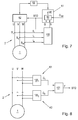
- a classical multi-channel structure can be built, as in Figure 8 in which the same calculation is carried out in each channel K1, K2, for example in which a monitoring unit 100 1 , 100 2 with calculation blocks 10 and monitoring blocks 60 is implemented in each channel K1, K2.
- the physical variable G1, G2 calculated in each channel K1, K2 can then be compared with one another in a computing unit 101. If the physical quantities G1, G2 calculated in the various channels K1, K2 are not equal (preferably within a predetermined tolerance band), a signal F can likewise be output, for example a pulse lock STO can be activated. This redundancy can further increase security.
- the determined, currently acting state variable G can be compared in a comparison block 50 with a limit G zul and a corresponding comparison result VE be output.
- the specification of a permissible limit value G zul of the state variable G can be effected , for example, via a higher-level control unit (not shown) and can also change over time.
- a limit value G zul may also change over time during operation of the three-phase synchronous machine 1, for example when the three-phase synchronous machine 1 during a different tasks are performed at certain times. This comparison can also be performed in each channel of a multi-channel structure.
- the plausibility signal S can also be used to activate the comparison block 50 in the case of a positive plausibility check or to deactivate it in the other case.
- the comparison block 50 can also be supplied with the plausibility signal S, as in FIG Fig. 6 indicated.
- this can also be used in the comparison block 50 to always output a negative comparison result VE or to activate the pulse inhibit STO.
- the comparison made in the comparison block 50 provides information about the achievement, exceeding or even not reaching of possible ranges or values of the state variable G, which is to be avoided for safety reasons, for example.
- the output of the comparison result VE enables a plurality of possible actions, which can be set based on the comparison result VE. For example, corresponding status messages can be made, such as green or red light indicators, an audible warning, the issuing of an error message to a higher-level control unit, etc.
- a negative comparison, ie reaching or even exceeding an allowable limit G zul can also for immediate stop the three-phase Synchronous machine 1 lead, for example in the form of an activated pulse lock STO. As a result of the pulse lock STO receives the three-phase synchronous machine 1 no supply current which can lead to a rotational movement. The pulse lock STO thus ensures that the three-phase synchronous machine 1 is stopped.
- the three-phase synchronous machine 1 is supplied in a known manner by a power unit 52, for example in the form of a converter circuit, with electric current.
- the power unit 52 is for this purpose controlled by a motor control unit 53, for example in the form of a known PWM signal.
- the engine control unit 53 can also receive commands or manipulated variable specifications, such as a desired torque, from a higher-level control unit 51 for this purpose.
- the engine control unit 53 could also be integrated in the higher-level control unit 51 for this purpose.
- the phase currents I u, I v, I w of the multi-phase current network 2 which connects the power section 52 to the three-phase synchronous machine 1 are detected and the state quantity G of the three-phase synchronous machine 1 is determined therefrom as described in the monitoring unit 100th
- the comparison block 50 is integrated in the higher-level control unit 51 (either as hardware or software).
- the comparison block 50 receives the determined state variable G, and possibly also the plausibility signal S, and compares the state variable G with a predetermined permissible limit G zul .
- the comparison result VE can be further processed in the higher-level control unit 51, for example in the form of a SLT function in the case of a torque as a state variable G.
- various actions can be triggered.
- the triggering of a pulse lock STO of the three-phase synchronous machine 1 is common, with this is stopped.
- the pulse lock STO can also be triggered by the monitoring unit 100.
Landscapes
- Engineering & Computer Science (AREA)
- Power Engineering (AREA)
- Physics & Mathematics (AREA)
- General Physics & Mathematics (AREA)
- Control Of Ac Motors In General (AREA)
Abstract
Zur sicheren Ermittlung einer Zustandsgröße (G) einer Drehstrom-Synchronmaschine (1), die von einem Mehrphasenstromnetz (2) mit n Phasen (U,...,N), mit n≥3, mit elektrischem Strom versorgt wird, werden die Stromwerte von zumindest n-1 Phasenströmen (Iu,...,In-1) aus zumindest n-1 Phasen (U,...,N-1) des Mehrphasenstromnetzes (2) erfasst. Es wird mittels der zumindest n-1 aktuellen Stromwerte (Iu,...,In-1) die Zustandsgröße (G) ermittelt, wobei die Stromwerte aller n Phasenströme (Iu,...,In) aus dem n-phasigen Mehrphasenstromnetz (2) erfasst und die n Phasenströme (Iu,...,In) miteinander verknüpft werden. Das Ergebnis der Verknüpfung aller n Phasenströme (Iu,...,In) wird für eine Plausibilitätsprüfung der für die Ermittlung der Zustandsgröße (G) verwendeten n-1 Phasenströme (Iu,...,In-1) herangezogen.

Description
Die Erfindung betrifft ein Verfahren und eine Vorrichtung zur sicheren Ermittlung einer Zustandsgröße einer Drehstrom-Synchronmaschine, die von einem Mehrphasenstromnetz mit n≥3 Phasen, mit elektrischem Strom versorgt wird, wobei Stromwerte von zumindest n-1 Phasenströmen aus zumindest n-1 Phasen eines Mehrphasenstromnetzes erfasst werden und mittels der zumindest n-1 ersten aktuellen Stromwerte eine Zustandsgröße berechnet wird. Weiters betrifft die Erfindung die Verwendung des Verfahrens zum sicheren Betreiben einer Drehstrom-Synchronmaschine.The invention relates to a method and a device for the reliable determination of a state variable of a three-phase synchronous machine, which is supplied with electric current by a multi-phase current network with n≥3 phases, wherein current values of at least n-1 phase currents from at least n-1 phases of a multi-phase current network are detected and by means of the at least n-1 first current current values, a state variable is calculated. Furthermore, the invention relates to the use of the method for safe operation of a three-phase synchronous machine.
Im Zusammenhang mit elektrischen Antrieben, in Form von mit Elektromotoren angetriebenen Bauteilen, finden die unterschiedlichsten Sicherheitsfunktionen und Sicherheitsüberwachungen Anwendung. Deren Aufgabe besteht darin, die Risiken sowohl für Mensch als auch für den elektrischen Antrieb selbst bzw. damit angetriebenen Anlagen, zu reduzieren.In connection with electric drives, in the form of components driven by electric motors, a wide variety of safety functions and safety monitors are used. Their task is to reduce the risks for both humans and for the electric drive itself or driven there plants.
Zu einer der gängigsten Überwachungsfunktionen, in Verbindung mit elektrischen Antrieben, gehört das sicher begrenzte Moment. Im Allgemeinen wird in diesem Zusammenhang von der "Safe Limited Torque Funktion" bzw. der "SLT-Funktion" gesprochen, weshalb im Weiteren auch nur noch die Bezeichnung SLT-Funktion genutzt wird.One of the most common monitoring functions, in conjunction with electric drives, is the surely limited moment. In general, in this context, the "Safe Limited Torque function" or the "SLT function" spoken, which is why in addition also only the term SLT function is used.
Aufgabe einer SLT-Funktion ist es, zu verhindern, dass ein elektrischer Antrieb einen Grenzwert bzw. ein festgelegtes Drehmoment, oder bei der Nutzung eines Linearmotors eine festgelegte Kraft überschreitet. Dazu wird in der Regel das aktuelle Drehmoment des Elektromotors, bzw. die aktuelle Kraft im Falle eines Linearmotors, oder ein Drehmoment an einer anderen Stelle des Antriebs, durch die SLT-Funktion überwacht. Im Weiteren wird in Folge oftmals ein Drehmoment des elektrischen Antriebs erwähnt, wobei die Ausführungen in analoger Weise auch für die Kraft eines Linearmotors gelten.The task of a SLT function is to prevent an electric drive from exceeding a set value or a defined torque, or when using a linear motor, a defined force. For this purpose, the current torque of the electric motor, or the current force in the case of a linear motor, or a torque at another point of the drive, is monitored by the SLT function in the rule. In addition, a torque of the electric drive is often mentioned as a result, the statements also apply analogously to the force of a linear motor.
Dadurch, dass ein zulässiger Wert des Drehmomentes des elektrischen Antriebs nicht überschritten wird, ergibt sich eine gewisse Sicherheitsfunktion, beispielsweise wenn Fremdkörper in eine vom elektrischen Antrieb angetriebene Anlage eingezogen werden. Dabei kann durch die Sicherheitsfunktion beispielsweise der Antrieb drehmomentfrei geschaltet werden, oder auch lediglich eine Warnmeldung ausgegeben werden. Dies trägt dazu bei, dass beispielsweise das Bedienpersonal einer Anlage, bzw. die Anlage selbst vor Schaden bewahrt werden kann. Ein Überschreiten eines zulässigen Drehmoments wird zuerst durch die SLT-Funktion registriert. Grundsätzlich muss, um eine vorliegende Gefahrensituation beurteilen zu können, das aktuelle Drehmoment bestimmt werden. Da die Entscheidung zur Deaktivierung des Antriebs, oder die Ausgabe eines Warnsignals auf diese Bestimmung des Drehmoments basiert, erfolgt diese meistens mehrkanalig, um durch Redundanz eine gewisse Sicherheit zu garantieren. Das Drehmoment (Kraft) ist allerdings nur eine Zustandsgröße des elektrischen Antriebs, auf die die SLT-Funktion abstellen kann. Anstelle des Drehmoments könnten auch die Motorströme überwacht werden. Ebenso könnte die Momentanleistung des Elektromotors als Zustandsgröße herangezogen werden. Wesentlich hierbei ist, dass die SLT-Funktion auf eine erfassbare oder ermittelbare Zustandsgröße des elektrischen Antriebs, auf deren Richtigkeit vertraut werden kann, abstellt.The fact that an allowable value of the torque of the electric drive is not exceeded, there is a certain safety function, for example, when foreign objects are drawn into a driven by the electric drive system. In this case, for example, the drive can be switched torque-free by the safety function, or even a warning message can be issued. This contributes to the fact that, for example, the operator of a system, or the system itself can be protected from damage. Exceeding an allowable torque is first registered by the SLT function. Basically, in order to assess an existing hazard situation, the current torque must be determined. Because the decision to disable the drive, or the issue of a warning signal to this determination of torque This is mostly multi-channel, to guarantee a certain degree of security through redundancy. The torque (force), however, is only a state variable of the electric drive, on which the SLT function can turn off. Instead of the torque, the motor currents could also be monitored. Likewise, the instantaneous power of the electric motor could be used as a state variable. It is essential here that the SLT function adjusts to a detectable or ascertainable state variable of the electric drive, the correctness of which can be trusted.
Dazu sieht beispielsweise die
Zur Berechnung des Stromraumzeigers werden in der
Sollte im Dreiphasennetz das mögliche weitere, dritte Strompaar zur weiteren Kontrolle herangezogen werden, hat einer der beiden Mikrocontroller die Rechenoperation zweimal durchzuführen. Zwar steht auf diese Weise ein dritter Wert zur Kontrolle des errechneten Drehmoments zur Verfügung, dabei ist jedoch auch ein möglicher Fehler in einem der beiden Mikrocontroller zu berücksichtigen. Unter Umständen führt ein fehlerhaft gemessener aktueller Stromwert in Kombination mit einem fehlerhaften Mikrocontroller dazu, dass ein Fehler beim Vergleich der letztlich fehlerbehafteten Drehmomente nicht detektiert wird.If, in the three-phase network, the possible further, third current pair is used for further checking, one of the two microcontrollers has the arithmetic operation twice perform. Although in this way a third value is available for controlling the calculated torque, a possible error in one of the two microcontrollers must also be taken into account. Under certain circumstances, an erroneously measured current current value in combination with a faulty microcontroller will result in an error not being detected when comparing the ultimately faulty torques.
Damit kann das für das sichere Stillsetzen des Antriebs benötigte Drehmoment gemäß dem Stand der Technik nicht mit ausreichender Sicherheit ermittelt werden, bzw. kann es Situationen geben, in denen ein fehlerhaft ermitteltes Drehmoment nicht erkannt wird. Beides ist für eine Sicherheitsfunktion problematisch.Thus, the torque required for the safe shutdown of the drive according to the prior art can not be determined with sufficient certainty, or there may be situations in which an incorrectly determined torque is not detected. Both are problematic for a security function.
Die Aufgabe der vorliegenden Erfindung besteht darin, ein Verfahren und eine Vorrichtung zur sicheren Ermittlung einer Zustandsgröße einer in einem Mehrphasenstromnetz mit drei oder mehr Phasen befindlichen Drehstrom-Synchronmaschine anzugeben.The object of the present invention is to specify a method and a device for the reliable determination of a state variable of a three-phase synchronous machine located in a multi-phase current network with three or more phases.
Diese Aufgabe wird durch die vorliegende Erfindung dadurch gelöst, dass im Mehrphasennetz, wobei n≥3 Phasen vorhanden sind, alle n aktuellen Stromwerte der n Phasenströme erfasst und für eine Plausibilitätsprüfung der zumindest n-1 ersten aktuellen Stromwerte herangezogen werden. Dadurch wird in einem frühzeitigen Stadium geprüft, ob Stromwerte, welche zu weiteren Berechnungen herangezogen werden sollen, zur weiteren Berechnung geeignet bzw. plausibel sind. Eine Überprüfung erfolgt somit nicht, wie im Falle des dreiphasen-Drehstromnetzes im Stand der Technik, durch den Vergleich zweier aus unterschiedlichen Stromwerten errechneten physikalischen Größen. Die erfassten aktuellen Stromwerte selbst werden in der vorliegenden Erfindung für eine Überprüfung herangezogen. Dadurch wird eine unmittelbare Kontrolle ermöglicht und Fehlerakkumulationen, durch weitere Zwischenschritte bzw. Berechnungen, werden minimiert.This object is achieved by the present invention in that in the polyphase network, where n≥3 phases are present, all n current current values of the n phase currents are detected and used for a plausibility check of the at least n-1 first current current values. As a result, it is checked at an early stage whether current values which are to be used for further calculations are suitable or plausible for further calculation. A check is thus not made, as in the case of the three-phase three-phase network in the prior art, by comparing two calculated from different current values physical quantities. The detected actual current values themselves are used in the present invention for a check. This allows immediate control and minimizes error accumulations through further intermediate steps or calculations.
In vorteilhafter Weise kann die Plausibilitätsprüfung derart erfolgen, dass das erste Kirchhoff'sche Gesetz, auch Knotenregel genannt, auf die aktuellen Phasenströme angewandt wird. Das erste Kirchhoff'sche Gesetz besagt, dass die Summe in einem Knotenpunkt Null ergeben muss, oder anders formuliert die Summe der zufließenden Ströme der Summe der abfließenden Ströme entsprechen muss. Die Anwendung des ersten Kirchhoff'schen Gesetzes ist im Falle einer vorliegenden Sternschaltung der Statorwicklungen direkt möglich, sofern der Sternpunkt nicht geerdet ist. Im Falle einer n-Eckschaltung der Statorwicklungen kann ebenso direkt eine Summenbildung der Phasenströme erfolgen. Aus dem Ergebnis der Summe ist eine einfache Kontrolle der Plausibilität der erfassten Ströme möglich.Advantageously, the plausibility check can be carried out such that the first Kirchhoff's law, also called node rule, is applied to the current phase currents. The first Kirchhoff's law states that the sum in a node must be zero, or in other words the sum of the inflowing streams must equal the sum of the outflowing streams. The application of the first Kirchhoff's law is directly possible in the case of a present star connection of the stator windings, if the neutral point is not earthed. In the case of a n-corner circuit of the stator windings, a summation of the phase currents can also be effected directly. From the result of the sum, a simple control of the plausibility of the detected currents is possible.
In vorteilhafter Weise wird das Ergebnis der Plausibilitätsprüfung in Form eines Plausibilitätssignals ausgegeben. Eine derartige Ausgabe, welche beispielsweise zu einem optischen oder akustischen Hinweis führen kann, erlaubt es frühzeitig einen Fehler in der Erfassung der Stromwerte anzuzeigen oder einen erkannten Fehler auf andere Weise zu verarbeiten.Advantageously, the result of the plausibility check is output in the form of a plausibility signal. Such an output, which, for example, to an optical or acoustic indication, it is possible at an early stage to indicate an error in the detection of the current values or to process a detected error in another way.
Eine vorteilhafte Ausgestaltung sieht vor, dass aus den zumindest n-1 ersten aktuellen, Stromwerten eine erste Stromkomponente gebildet wird. Diese erste Stromkomponente kann bereits selbst eine Zustandsgröße darstellen oder daraus eine weitere Zustandsgröße berechnet werden, beispielsweise mittels Verknüpfung mit einer Rechenkonstante. Dazu sieht eine vorteilhafte Ausgestaltung vor, dass als Zustandsgröße ein Drehmoment berechnet wird.An advantageous embodiment provides that a first current component is formed from the at least n-1 first current current values. This first current component can itself already represent a state variable or a further state variable can be calculated therefrom, for example by means of linking with a calculation constant. For this purpose, an advantageous embodiment provides that a torque is calculated as the state variable.
Vorteilhaft ist vorgesehen, dass die aktuell wirkende Zustandsgröße mit einem Grenzwert verglichen wird und ein Vergleichsergebnis ausgegeben wird. Der Vergleich gibt Auskunft über das Erreichen möglicher Bereiche, welche es beispielsweise aus Sicherheitsgründen zu vermeiden gilt. Die Ausgabe des Vergleichsergebnisses ermöglicht eine Vielzahl an möglichen Handlungen, welche basierend auf das Vergleichsergebnis gesetzt werden können.Advantageously, it is provided that the currently acting state variable is compared with a limit value and a comparison result is output. The comparison provides information on the achievement of possible areas, which should be avoided for safety reasons, for example. The output of the comparison result allows a variety of possible actions that can be set based on the comparison result.
Dabei kann vorteilhaft vorgesehen sein, dass das Erreichen oder Überschreiten des Grenzwertes eine Impulssperre auslöst. Infolge einer Impulssperre erhält der elektrische Antrieb bzw. die Mehrphasen-Synchronmaschine keinen Strom mehr, der zu einer Drehbewegung führen kann.It can be advantageously provided that the achievement or exceeding of the limit triggers a pulse lock. As a result of a pulse lock receives the electric drive or multi-phase synchronous machine no more power that can lead to a rotational movement.
Die erfindungsgemäße Ausgestaltung kann auch mehrkanalig oder mit redundanten Bausteinen erfolgen, sodass eine gewisse Ausfallsicherheit gegeben ist. Die somit parallel ermittelten Ergebnisse können verglichen werden und im Falle der Ungleichheit kann ein Signal ausgegeben werden, oder die Impulssperre ausgelöst werden.The inventive design can also be multi-channel or redundant blocks, so that a certain reliability is given. The results thus determined in parallel can be compared and in the case of inequality a signal can be output or the pulse inhibit can be triggered.
Die gegenständliche Erfindung wird nachfolgend unter Bezugnahme auf die
-
Fig.1 die drei Phasen des dreiphasigen Mehrphasenstromnetzes mit dem statorfesten und dem rotorfesten Koordinatensystem, -
Fig.2 die Erfassung zweier aktueller Stromwerte und die Bildung zweier Stromkomponenten, -
Fig.3 die Bildung einer Zustandsgröße, -
Fig.4 die zweikanalige Auswertung nach Stand der Technik, -
Fig.5 das erfindungsgemäße Verfahren zur Berechnung einer Zustandsgröße, -
Fig.6 Vergleich der aktuell wirkende Zustandsgröße mit einem Grenzwert und -
Fig.7 eine Drehstrom-Synchronmaschine mit sicherer Ermittlung einer Zustandsgröße. -
Fig.8 eine mehrkanalige Struktur der Erfindung
-
Fig.1 the three phases of the three-phase multiphase power system with the stator-fixed and rotor-fixed coordinate system, -
Fig.2 the acquisition of two current values and the formation of two current components, -
Figure 3 the formation of a state variable, -
Figure 4 the two-channel evaluation according to the prior art, -
Figure 5 the method according to the invention for calculating a state variable, -
Figure 6 Comparison of the currently acting state variable with a limit value and -
Figure 7 a three-phase synchronous machine with reliable determination of a state variable. -
Figure 8 a multi-channel structure of the invention
Die
Stator und dem Rotor einer Drehstrom-Synchronmaschine 1 wird üblicherweise jeweils ein zweiachsiges rechtwinkliges Koordinatensystem zugeordnet. In
In
Mithilfe einer linearen Transformation, der bekannten Clarke-Transformation, ist es allgemein möglich n-phasige Größen der Drehstrom-Synchronmaschine 1, beispielsweise die n Phasenströme des Stators oder den Stromraumzeiger, in das zweiachsige statorfeste Koordinatensystem AB mit einer Komponente in Richtung der Achsen A und einer Komponente in Richtung der Achse B überzuführen. Die Wicklungen des Stators können jedoch in Stern oder in n-Eck geschaltet werden. Im Falle einer n-Eckschaltung muss bekanntermaßen berücksichtigt werden, dass die gemessenen Phasenströme Iu,...,In der Phasen U,...,N über die bekannten n Wicklungsimpedanzen Z12, Z23,...,Zn1 in die n Ströme der n Wicklungen (und damit in den Stromraumzeiger) umgerechnet werden, bevor eine Clarke-Transformation durchgeführt werden kann. Im Falle der Sternschaltung entsprechen die gemessenen Phasenströme Iu,...,In in den Phasen U,...N bereits den Strömen in den Wicklungen. Unter Berücksichtigung, dass sowohl in Sternschaltung des Stators mit nicht geerdetem Sternpunkt, als auch in n-Eckschaltung des Stators, die Summe der aktuellen Stromwerte Iu,...,In immer Null ist, ist bekanntermaßen das Erfassen von lediglich n-1 der aktuellen Phasenströme Iu,...,In-1 notwendig, womit die Clarke-Transformation vereinfacht werden kann. Die nachfolgend beschrieben Erfindung ist damit gleichermaßen für eine Sternschaltung, als auch eine n-Eckschaltung der n Phasen der Drehstrom-Synchronmaschine 1 anwendbar. In weiterer Folge wird zur Beschreibung der Erfindung ohne Einschränkung der Allgemeinheit von einer Sternschaltung des Stators ausgegangen, weswegen auch auf die Phasenströme Iu,...,In referenziert wird, da sie in diesem Fall mit den Strömen der Wicklungen identisch sind.By means of a linear transformation, the known Clarke transformation, it is generally possible n-phase variables of the three-phase
Im Falle des im Beispiel dargestellten dreiphasigen (n=3) Mehrphasenstromnetzes kann die Clarke-Transformation angewendet werden, um dreiphasige Größen, wie die aktuellen Stromwerte der Phasenströme Iu, Iv, Iw in das zweiachsige Koordinatensystem AB des Stators mit den Achsen A und B überzuführen. Unter Berücksichtigung, dass die Summe der drei aktuellen Stromwerte Iu, Iv, Iw immer Null ist, ist im Falle eines Dreiphasennetzes für die Clarke-Transformation das Erfassen von lediglich zwei (n-1) der drei (n) aktuellen Stromwerte Iu, Iv, Iw notwendig, wie in
Unter Berücksichtigung des zuvor erwähnten Verdrehwinkels ϕ können mittels eines einfachen trigonometrischen Zusammenhangs auch eine entsprechende erste Stromkomponente Iq und eine zweite Stromkomponente Id im zweiachsigen rechtwinkligen Koordinatensystem QD des Rotors mit den Achsen Q und D gebildet werden. Diese erste Stromkomponente Iq und zweite Stromkomponente Id ergeben als vektorielle Summe den rotierenden Stromraumzeiger. Die erste Stromkomponente Iq und eine zweite Stromkomponente Id können bekanntermaßen mittels der Park-Transformation aber auch direkt aus den gemessenen Phasenströmen Iu, Iv, Iw unter Zuhilfenahme des Verdrehwinkels ϕ ermittelt werden. Dazu ist es üblich, den Verdrehwinkel ϕ, der die Rotorlage repräsentiert, mittels entsprechender Sensorik, wie z.B. einem bekannten Drehwinkelgeber, zu erfassen. Die erste Stromkomponente Iq liegt quer zum Fluss des Rotor-Permanentmagneten und wird daher üblicherweise als Querstrom bezeichnet. Somit ist die erste Stromkomponente Iq jene Stromkomponente, welche für das Erzeugen des Drehmoments der Drehstrom-Synchronmaschine 1 verantwortlich ist. Dazu kann bekanntermaßen unter Verwendung einer entsprechenden Motor-Drehmomentkonstanten KT aus der errechneten ersten Stromkomponente Iq ein momentanes Drehmoment M der Drehstrom-Synchronmaschine 1 bestimmt werden.Taking into account the above-mentioned twist angle φ, a corresponding first current component I q and a second current component I d in the biaxial rectangular coordinate system QD of the rotor with the axes Q and D can be formed by means of a simple trigonometric relationship. This first current component I q and second current component I d yield as a vectorial sum the rotating current space pointer. As is known, the first current component I q and a second current component I d can also be determined directly from the measured phase currents I u , I v , I w by means of the Park transformation, with the aid of the angle of rotation φ. For this purpose, it is customary to detect the angle of rotation φ, which represents the rotor position, by means of corresponding sensors, such as a known rotary encoder. The first current component I q is transverse to the flux of the rotor permanent magnet and is therefore commonly referred to as a cross-flow. Thus, the first current component I q is the current component which is responsible for generating the torque of the three-phase
Die Stromkomponenten Ia, Ib des statorfesten Koordinatensystems bzw. gleichwertig die Stromkomponenten Iq, Id des rotorfesten Koordinatensystems werden bekanntermaßen verwendet, um Zustandsgrößen der Drehstrom-Synchronmaschine 1, wie z.B. ein Drehmoment oder eine Leistung, zu ermitteln. Diese Stromkomponenten Ia, Ib und Iq, Id können aber auch selbst als Zustandsgrößen angesehen werden.
Die Transformationseinheit T und die Berechnungseinheit 9 können dabei natürlich auch in einer Einheit integriert sein, z.B. in einem Berechnungsbaustein 10, wie in
Zur Berechnung der Zustandsgröße G kann dem Transformationsbaustein T auch der Verdrehwinkel ϕ zugeführt werden, um die obigen Transformationen berechnen zu können. In einer vereinfachten Ausführung kann auf den Verdrehwinkel ϕ auch verzichtet werden. In diesem Fall wird angenommen, dass der Stromraumzeiger der drehmomentenbildenden Stromkomponente iq entspricht. Damit wird eine Stromkomponente iq,max ermittelt, die größer als die, oder zumindest gleich der tatsächlich wirkenden, drehmomentbildende Stromkomponente Iq ist. Wird mit dieser Stromkomponente iq,max die Zustandsgröße G berechnet, enthält die Zustandsgröße G somit eine Art Reserve, da die tatsächliche Zustandsgröße G niemals größer als die berechnete Zustandsgröße G sein kann.To calculate the state variable G, the transformation element T can also be supplied with the angle of rotation φ in order to be able to calculate the above transformations. In a simplified embodiment, the twist angle φ can also be dispensed with. In this case, it is assumed that the current space vector corresponds to the torque-forming current component iq. Thus, a current component i q, max is determined which is greater than, or at least equal to, the actually acting, torque-forming current component I q . If the state variable G is calculated with this current component i q, max, then the state variable G contains a kind of reserve, since the actual state variable G can never be greater than the calculated state variable G.
Es sei an dieser Stelle angemerkt, dass die Anwendung für Linearmotoren nicht ausgeschlossen ist. Bei der Zustandsgröße G kann es sich in diesem Fall um eine Kraft, welche der Linearmotor aufbringt, handeln. Die obigen Ausführungen gelten dabei analog.It should be noted at this point that the application for linear motors is not excluded. The state variable G may in this case be a force which the linear motor applies. The above statements apply analogously.
Das Drehmoment M der Drehstrom-Synchronmaschine 1 ist eine Zustandsgröße G, welche im Betrieb ein besonders hohes Gefahrenpotential mit sich bringen kann. Eine Drehstrom-Synchronmaschine 1 kommt beispielsweise bei Anlagen in der Produktions- und Fertigungstechnik als Antriebsmaschine zum Einsatz. Dabei ist das aufgebrachte Drehmoment M der Drehstrom-Synchronmaschine 1 letztlich für die möglichen auftretenden Kräfte verantwortlich. Um Schaden an Mensch und Maschine zu verhindern, darf das erzeugte Drehmoment M als Zustandsgröße G einen zuvor ausgewählten zulässigen Höchstwert Gzul, beispielsweise ein maximales Drehmoment Mzul, der Zustandsgröße nicht überschreiten, um beispielweise im Fall eines Verklemmens an oder in einer eben erwähnten Anlage Folgeschäden oder Verletzungen zu vermeiden. Solche Zustandsgrößen G werden daher oftmals redundant überwacht, insbesondere in sicherheitsgerichteten Anwendungen, in denen im Falle von Fehlern Gefahr für Mensch oder Maschine besteht. Dazu ist aber auch erforderlich, dass der ermittelten Zustandsgröße G vertraut werden kann.The torque M of the three-phase
Bei einer korrekten Bestimmung der aktuellen Stromwerte Iu, Iv, Iw und einer fehlerfreien Berechnung des ersten Drehmoments M10 und des zweiten Drehmoments M20, ergibt der Vergleich der beiden Drehmomente M10 und M20 im Vergleicher 40 (innerhalb festgelegter Toleranzbänder) keine Abweichung. In diesem Fall wird davon ausgegangen, dass die Drehmomente M10 bzw. M20 einem tatsächlich vorhandenen Drehmoment Mtats entsprechen. Das tatsächlich vorhandene Drehmoment Mtats wird einem Vergleichsbaustein 50 zugeführt, wo es mit einem zulässigen Drehmoment Mzul verglichen wird. Dieses zulässige Drehmoment Mzul stellt beispielsweise einen oberen Grenzwert dar, bei dem gerade noch ein sicheres Betreiben der Drehstrom-Synchronmaschine 1 gewährleistet werden kann. Wird das zulässige Drehmoment Mzul überschritten, wird ein Stillsetzen der Drehstrom-Synchronmaschine 1 veranlasst. Selbiges erfolgt bei einer, durch den Vergleicher 40 detektierten, Abweichung der beiden Drehmomente M10 und M20 voneinander.With correct determination of the actual current values I u, I v, I w and an error free computation of the first torque M 10 and the second torque M 20, the comparison of the two torques M 10 and M 20 results in the comparator 40 (within predetermined tolerance bands) no deviation. In this case, it is assumed that the torques M 10 and M 20 correspond to an actually existing torque M tats . The actual torque M tats is supplied to a
Dabei besteht jedoch die Gefahr, dass im Falle des oben ausgeführten Beispiels der Sensor Sv fehlerhaft ist und ein falscher aktueller Stromwert Iv in beiden Berechnungsbausteinen 10 und 20 zur Berechnung der Drehmomente M10 bzw. M20 herangezogen wird. In diesem Fall könnte es dazu kommen, dass ein Fehler in der Erfassung des aktuellen Stromwerts Iv im Zuge des Vergleichs der beiden Drehmomente M10 und M20 nicht detektiert wird, da sich die beiden Drehmomente M10 bzw. M20 dennoch gleichen. Das kann dazu führen, dass ein berechnetes Drehmoment M10, M20 kleiner ist, als ein tatsächlich wirkendes Drehmoment. Ist das berechnete Drehmoment M10, M20 auch noch kleiner als das zulässige Drehmoment Mzul, könnte das zu einer Verletzung der Sicherheit der Drehstrom-Synchronmaschine 1 führen. Ein Schaden an Mensch oder Maschine könnte damit nicht ausgeschlossen werden.However, there is a risk that, in the case of the above-described example, the sensor S v is faulty and a wrong current current value I v in both calculation blocks 10 and 20 is used to calculate the torques M 10 and M 20 . In this case, it could happen that an error in the detection of the current current value I v in the course of the comparison of the two torques M 10 and M 20 is not detected, since the two torques M 10 and M 20 are still the same. This can lead to a calculated torque M 10 , M 20 being smaller than an actually acting torque. If the calculated torque M 10 , M 20 even smaller than the allowable torque M zul , this could lead to a violation of the safety of the three-phase
Um dies zu vermeiden, kann in einer in
Anhand von
Es werden zumindest n-1 aktuelle Phasenströme Iu,...,In-1 aus n-1 Phasen U,...,N-1 des n-phasigen Mehrphasenstromnetzes 2 erfasst. Im gezeigten Ausführungsbeispiel beispielsweise zwei (n-1) Phasenströme Iu, Iv der Phasen U, V des dreiphasigen (n=3) Mehrphasenstromnetzes 2. Mittels dieser zumindest n-1 aktuellen Stromwerten der Phasenströme Iu,...,In-1 wird die aktuell wirkende Zustandsgröße G im Berechnungsbaustein 10 wie beschrieben berechnet. Zusätzlich werden die aktuellen Stromwerte aller n Phasenströme Iu,...,In aus dem n-phasigen Netz erfasst und für eine Plausibilitätsprüfung der zumindest n-1 Stromwerte der Phasenströme Iu,...,In-1 herangezogen. Es werden also alle n erfassten aktuellen Stromwerte aller Phasenströme Iu,...,In selbst für eine Überprüfung herangezogen. Dadurch wird eine unmittelbare Kontrolle ermöglicht und damit Fehlerakkumulationen durch weitere Berechnungen minimiert. So würde beispielsweise die Ermittlung einer Zustandsgröße G aus den aktuellen Phasenströmen Iu,...,In und eine darauffolgende Überprüfung der Plausibilität der aktuellen Phasenströme Iu,..., In aus der zuvor ermittelten Zustandsgröße G einen zusätzlichen Rechenschritt und damit eine weitere Fehlerquelle bedeuten.At least n-1 current phase currents I u ,..., I n-1 are detected from n-1 phases U,..., N-1 of the n-phase polyphase
Hierzu ist ein Überwachungsbaustein 60 vorgesehen, dem die Stromwerte aller Phasenströme Iu,...,In zugeführt wird. Die Plausibilitätsprüfung der zumindest n-1 Stromwerte der Phasenströme Iu,...,In-1, die zur Ermittlung der Zustandsgröße G verwendet werden, erfolgt im Überwachungsbaustein 60 dadurch, dass alle n Phasenströme Iu,...,In miteinander verknüpft werden und das Ergebnis der Verknüpfung zur Plausibilisierung herangezogen wird. Es wird natürlich eine Verknüpfung verwendet, die zu einem bekannten, erwartenden Ergebnis führt. Vorzugsweise erfolgt die Verknüpfung durch Anwendung des ersten Kirchhoff'schen Gesetzes auf alle n Phasenströme Iu,...,In der n Phasen U,...N des Mehrphasenstromnetzes 2. Sowohl bei Sternschaltung, als auch bei n-Eck-Schaltung der Wicklungen der Drehstrom-Synchronmaschine 1 muss die Summe aller n Phasenströme Iu,...,In gleich Null sein. Auf diese Weise kann eine einfache Kontrolle der Plausibilität der n erfassten, aktuellen Stromwerte der Phasenströme Iu,...,In erfolgen. Ergibt die Summe der n Phasenströme Iu,...,In nicht Null, muss ein Fehler vorliegen, beispielsweise in Form eines defekten Stromsensors SU, SV, SW, eines beschädigten oder gelösten Kabels oder ähnliches. In jedem Fall ist dem Ergebnis der Berechnung der Zustandsgröße G im Falle einer negativen Plausibilitätsprüfung nicht zu trauen und es ist eine entsprechende Handlung zu setzen.For this purpose, a
Vorteilhaft wird das Ergebnis der Plausibilitätsprüfung vom Überwachungsbaustein 60 in Form eines Plausibilitätssignals S ausgegeben.Advantageously, the result of the plausibility check is output by the
Das ausgegebene Plausibilitätssignal S kann damit im beschriebenen Ausführungsbeispiel nach
Im Falle einer negativen Plausibilitätsprüfung würde das Plausibilitätssignal S z.B. anzeigen, dass zumindest einer der n Stromsensoren Su, Sv, Sw schadhaft ist bzw. fehlerhaft misst. Da dem zumindest einen Berechnungsbaustein 10 daher aktuelle Stromwerte Iu, Iv zugeführt werden, welche möglicherweise fehlerhaft sind, kann auch die errechnete Zustandsgröße G keine geeignete Basis für eine weitere Kontrolle der Funktion der Drehstrom-Synchronmaschine 1 darstellen. In diesem Fall kann das Plausibilitätssignal S auch zur Ausgabe einer negativen Statusmeldung, beispielsweise zur Aktivierung einer roten Warnleuchte oder dergleichen herangezogen werden, oder an eine übergeordnete Regelungseinheit zur weiteren Verarbeitung übermittelt werden. Selbstverständlich ist im negativen Fall auch das Aktivieren eines unmittelbaren Stopps der Drehstrom-Synchronmaschine 1, beispielsweise in Form einer Impulssperre STO (Save Torque Off Funktion), wie in
Der Berechnungsbaustein 10 und der Überwachungsbaustein 60 können separate Hardwareeinheiten sein, können aber auch in einer gemeinsamen Hardwareeinheit integriert sein, wie z.B. in einer Überwachungseinheit 100, wie in
Um eine besonders hohe Sicherheit zu erreichen, können der Berechnungsbaustein 10 und/oder der Überwachungsbaustein 60, bzw. die Überwachungseinheit 100, auch redundant ausgeführt werden. Dazu können beispielsweise mehreren Berechnungsbausteinen 10 unterschiedliche Paare von Stromwerten Iu, Iv, Iw zugeführt werden, aber auch mehrere Berechnungsbausteine 10, Überwachungsbausteine 60, bzw. Überwachungseinheiten 100, nebeneinander ausgeführt sein, um eine höhere Ausfallsicherheit zu erreichen. Werden an diesen redundanten Berechnungsbausteinen 10, Überwachungsbausteinen 60, bzw. Überwachungseinheiten 100, ungleiche Ergebnisse ausgegeben, so kann ebenfalls eine Impulssperre STO ausgelöst werden. Dazu können die Ergebnisse dieser Bausteine miteinander verglichen werden. Damit kann auch eine klassische mehrkanalige Struktur aufgebaut werden, wie in
Wie in
Das Plausibilitätssignal S kann auch verwendet werden, um den Vergleichsbaustein 50 im Falle einer positiven Plausibilitätsprüfung zu aktivieren oder im anderen Fall zu deaktivieren. Dazu kann dem Vergleichsbaustein 50 auch das Plausibilitätssignal S zugeführt werden, wie in
Der im Vergleichsbaustein 50 vorgenommene Vergleich gibt Auskunft über das Erreichen, Überschreiten oder auch nicht Erreichen möglicher Bereiche bzw. Werte der Zustandsgröße G, welche es beispielsweise aus Sicherheitsgründen zu vermeiden gilt. Die Ausgabe des Vergleichsergebnisses VE ermöglicht eine Vielzahl an möglichen Handlungen, welche basierend auf das Vergleichsergebnis VE gesetzt werden können. Beispielsweise können entsprechende Statusmeldungen erfolgen, wie z.B. grüne oder rote Leuchtanzeigen, ein akustisches Warnsignal, das Absetzen einer Fehlernachricht an eine übergeordnete Regelungseinheit, etc. Ein negativer Vergleich, also das Erreichen oder sogar Überschreiten eines zulässigen Grenzwertes Gzul kann auch zum unmittelbaren Stopp der Drehstrom-Synchronmaschine 1 führen, beispielsweise in Form einer aktivierten Impulssperre STO. Infolge der Impulssperre STO erhält die Drehstrom-Synchronmaschine 1 keinen Versorgungsstrom mehr der zu einer Drehbewegung führen kann. Die Impulssperre STO sorgt somit dafür, dass die Drehstrom-Synchronmaschine 1 stillgesetzt wird.The comparison made in the
Anhand von
Claims (13)
Applications Claiming Priority (1)
| Application Number | Priority Date | Filing Date | Title |
|---|---|---|---|
| ATA50553/2015A AT517400B1 (en) | 2015-06-25 | 2015-06-25 | Method and device for determining a physical variable of a polyphase synchronous machine |
Publications (3)
| Publication Number | Publication Date |
|---|---|
| EP3109999A2 true EP3109999A2 (en) | 2016-12-28 |
| EP3109999A3 EP3109999A3 (en) | 2017-01-11 |
| EP3109999B1 EP3109999B1 (en) | 2022-01-26 |
Family
ID=56148246
Family Applications (1)
| Application Number | Title | Priority Date | Filing Date |
|---|---|---|---|
| EP16175377.7A Active EP3109999B1 (en) | 2015-06-25 | 2016-06-21 | Method and device for determining a physical variable of a multi-phase synchronous machine |
Country Status (4)
| Country | Link |
|---|---|
| US (1) | US10060983B2 (en) |
| EP (1) | EP3109999B1 (en) |
| AT (1) | AT517400B1 (en) |
| CA (1) | CA2933948A1 (en) |
Cited By (3)
| Publication number | Priority date | Publication date | Assignee | Title |
|---|---|---|---|---|
| WO2019092657A1 (en) * | 2017-11-10 | 2019-05-16 | Protean Electric Limited | A control device |
| CN112701988A (en) * | 2020-12-23 | 2021-04-23 | 欧瑞传动电气股份有限公司 | Runaway starting method suitable for high-speed permanent magnet synchronous motor |
| EP3828564A1 (en) | 2019-11-29 | 2021-06-02 | B&R Industrial Automation GmbH | Validation of phase currents of a multi-phase system |
Families Citing this family (2)
| Publication number | Priority date | Publication date | Assignee | Title |
|---|---|---|---|---|
| US11211851B2 (en) * | 2019-05-10 | 2021-12-28 | Rockwell Automation Technologies, Inc. | System and method for providing safe limited force producing power in a motor |
| WO2021011389A1 (en) * | 2019-07-17 | 2021-01-21 | Kollmorgen Corporation | Method and apparatus for the safe limitation of motor torque in a three-phase drive |
Family Cites Families (9)
| Publication number | Priority date | Publication date | Assignee | Title |
|---|---|---|---|---|
| DE10251095A1 (en) * | 2002-11-05 | 2004-05-19 | Daimlerchrysler Ag | Electric machine operating method for motor vehicle, by determining reliable torque from desired torque and detecting deviation of instantaneous torque from reliable torque |
| DE102006042038B3 (en) * | 2006-09-07 | 2008-02-07 | Siemens Ag | Field-oriented driven inverter-fed three-phase alternating current motor torque limiting method, involves generating impulse resetting signal when threshold value exceeds or torque-forming current components are unequal |
| DE102009040692B4 (en) * | 2009-09-04 | 2019-03-21 | Siemens Aktiengesellschaft | breakers |
| DE102010006594B4 (en) * | 2010-02-01 | 2020-12-31 | Sew-Eurodrive Gmbh & Co Kg | Propulsion system and method for operating a propulsion system |
| DE102010006593B4 (en) * | 2010-02-01 | 2020-12-17 | Sew-Eurodrive Gmbh & Co Kg | Propulsion system and method for operating a propulsion system |
| DE102011075387A1 (en) | 2011-05-06 | 2012-11-08 | Robert Bosch Gmbh | Method and device for monitoring a torque of an electric motor |
| DE102011108417B4 (en) * | 2011-07-26 | 2021-02-04 | Sew-Eurodrive Gmbh & Co Kg | Propulsion system and method for operating a propulsion system |
| US9054515B2 (en) * | 2013-06-12 | 2015-06-09 | Infineon Technologies Austria Ag | Current measurement and overcurrent detection |
| DE102014223236A1 (en) * | 2014-11-14 | 2016-05-19 | Robert Bosch Gmbh | Power converter and method for operating a power converter |
-
2015
- 2015-06-25 AT ATA50553/2015A patent/AT517400B1/en not_active IP Right Cessation
-
2016
- 2016-06-21 EP EP16175377.7A patent/EP3109999B1/en active Active
- 2016-06-23 CA CA2933948A patent/CA2933948A1/en not_active Abandoned
- 2016-06-24 US US15/191,894 patent/US10060983B2/en active Active
Non-Patent Citations (1)
| Title |
|---|
| None * |
Cited By (6)
| Publication number | Priority date | Publication date | Assignee | Title |
|---|---|---|---|---|
| WO2019092657A1 (en) * | 2017-11-10 | 2019-05-16 | Protean Electric Limited | A control device |
| CN110022104A (en) * | 2017-11-10 | 2019-07-16 | 普罗蒂恩电子有限公司 | Control device |
| US11251737B2 (en) | 2017-11-10 | 2022-02-15 | Protean Electric Limited | Control device |
| EP3828564A1 (en) | 2019-11-29 | 2021-06-02 | B&R Industrial Automation GmbH | Validation of phase currents of a multi-phase system |
| US11415610B2 (en) | 2019-11-29 | 2022-08-16 | B&R Industrial Automation GmbH | Validation of phase currents in a multi-phase system |
| CN112701988A (en) * | 2020-12-23 | 2021-04-23 | 欧瑞传动电气股份有限公司 | Runaway starting method suitable for high-speed permanent magnet synchronous motor |
Also Published As
| Publication number | Publication date |
|---|---|
| EP3109999A3 (en) | 2017-01-11 |
| EP3109999B1 (en) | 2022-01-26 |
| CA2933948A1 (en) | 2016-12-25 |
| AT517400B1 (en) | 2017-06-15 |
| US20160377682A1 (en) | 2016-12-29 |
| AT517400A1 (en) | 2017-01-15 |
| US10060983B2 (en) | 2018-08-28 |
Similar Documents
| Publication | Publication Date | Title |
|---|---|---|
| EP3109999B1 (en) | Method and device for determining a physical variable of a multi-phase synchronous machine | |
| DE102006042038B3 (en) | Field-oriented driven inverter-fed three-phase alternating current motor torque limiting method, involves generating impulse resetting signal when threshold value exceeds or torque-forming current components are unequal | |
| EP2309641A2 (en) | Method and device for error-free monitoring of an electric motor drive | |
| WO2012152463A2 (en) | Method and device for monitoring a torque of an electric motor | |
| DE102015226382A1 (en) | Method and arrangement for monitoring a PSM machine | |
| DE112017003161T5 (en) | Power conversion device | |
| DE10163010B4 (en) | Method and device for safely monitoring the speed of an electrical machine | |
| WO2019115143A1 (en) | Method for checking plausibility in the power supply of an electric motor | |
| EP1253490B1 (en) | Method and device for secure speed monitoring | |
| DE112018007041B4 (en) | Control device for an electric motor and method for detecting a cable disconnection | |
| WO2001011747A1 (en) | Device for monitoring the measuring system of an electric drive | |
| DE10041606B4 (en) | Electromotive drive and method for operating an electronically commutated electric motor | |
| DE10035783A1 (en) | Device for monitoring a measuring system of an electric drive | |
| DE102005045284A1 (en) | Speed monitoring device | |
| DE102014117091A1 (en) | Motor control with a function for detecting abnormalities of the power transmission unit between the engine and the main shaft | |
| EP2568596B1 (en) | Method and processing unit for determining the position of the rotor of a synchronous machine relative to the stator of the synchronous machine | |
| WO2004005938A1 (en) | Device for determining the rotational speed of a rotating machine part using redundant sensors and evaluation circuits | |
| DE102007017285A1 (en) | Method for monitoring three-phase machine, involves supplying input parameters of converter unit, where one of these input parameters is commutating angle of three-phase machine to be operated | |
| DE202019102429U1 (en) | Robotic gripper system with redundant torque sensors | |
| DE10154690A1 (en) | Procedure for the safety-related speed monitoring of a regulated drive motor | |
| EP3014756B1 (en) | Method for detecting an incorrect angular position of an electric motor | |
| EP3740828B1 (en) | Method for checking a time-discrete signal value of a sensor for freedom from errors | |
| DE102012223581A1 (en) | Apparatus and method for monitoring signal levels | |
| EP3532857B1 (en) | Device and method for diagnosing the detection of a multi-phase electric current | |
| DE10100565B4 (en) | A method of determining a torque applied by an asynchronous electric motor |
Legal Events
| Date | Code | Title | Description |
|---|---|---|---|
| PUAI | Public reference made under article 153(3) epc to a published international application that has entered the european phase |
Free format text: ORIGINAL CODE: 0009012 |
|
| STAA | Information on the status of an ep patent application or granted ep patent |
Free format text: STATUS: THE APPLICATION HAS BEEN PUBLISHED |
|
| PUAL | Search report despatched |
Free format text: ORIGINAL CODE: 0009013 |
|
| AK | Designated contracting states |
Kind code of ref document: A2 Designated state(s): AL AT BE BG CH CY CZ DE DK EE ES FI FR GB GR HR HU IE IS IT LI LT LU LV MC MK MT NL NO PL PT RO RS SE SI SK SM TR |
|
| AX | Request for extension of the european patent |
Extension state: BA ME |
|
| AK | Designated contracting states |
Kind code of ref document: A3 Designated state(s): AL AT BE BG CH CY CZ DE DK EE ES FI FR GB GR HR HU IE IS IT LI LT LU LV MC MK MT NL NO PL PT RO RS SE SI SK SM TR |
|
| AX | Request for extension of the european patent |
Extension state: BA ME |
|
| RIC1 | Information provided on ipc code assigned before grant |
Ipc: H02P 23/14 20060101AFI20161202BHEP Ipc: H02P 31/00 20060101ALI20161202BHEP |
|
| STAA | Information on the status of an ep patent application or granted ep patent |
Free format text: STATUS: REQUEST FOR EXAMINATION WAS MADE |
|
| 17P | Request for examination filed |
Effective date: 20170706 |
|
| RBV | Designated contracting states (corrected) |
Designated state(s): AL AT BE BG CH CY CZ DE DK EE ES FI FR GB GR HR HU IE IS IT LI LT LU LV MC MK MT NL NO PL PT RO RS SE SI SK SM TR |
|
| RAP1 | Party data changed (applicant data changed or rights of an application transferred) |
Owner name: B&R INDUSTRIAL AUTOMATION GMBH |
|
| STAA | Information on the status of an ep patent application or granted ep patent |
Free format text: STATUS: EXAMINATION IS IN PROGRESS |
|
| 17Q | First examination report despatched |
Effective date: 20200207 |
|
| STAA | Information on the status of an ep patent application or granted ep patent |
Free format text: STATUS: EXAMINATION IS IN PROGRESS |
|
| GRAP | Despatch of communication of intention to grant a patent |
Free format text: ORIGINAL CODE: EPIDOSNIGR1 |
|
| STAA | Information on the status of an ep patent application or granted ep patent |
Free format text: STATUS: GRANT OF PATENT IS INTENDED |
|
| INTG | Intention to grant announced |
Effective date: 20210916 |
|
| GRAS | Grant fee paid |
Free format text: ORIGINAL CODE: EPIDOSNIGR3 |
|
| GRAA | (expected) grant |
Free format text: ORIGINAL CODE: 0009210 |
|
| STAA | Information on the status of an ep patent application or granted ep patent |
Free format text: STATUS: THE PATENT HAS BEEN GRANTED |
|
| AK | Designated contracting states |
Kind code of ref document: B1 Designated state(s): AL AT BE BG CH CY CZ DE DK EE ES FI FR GB GR HR HU IE IS IT LI LT LU LV MC MK MT NL NO PL PT RO RS SE SI SK SM TR |
|
| REG | Reference to a national code |
Ref country code: GB Ref legal event code: FG4D Free format text: NOT ENGLISH |
|
| REG | Reference to a national code |
Ref country code: CH Ref legal event code: EP |
|
| REG | Reference to a national code |
Ref country code: AT Ref legal event code: REF Ref document number: 1466064 Country of ref document: AT Kind code of ref document: T Effective date: 20220215 |
|
| REG | Reference to a national code |
Ref country code: IE Ref legal event code: FG4D Free format text: LANGUAGE OF EP DOCUMENT: GERMAN |
|
| REG | Reference to a national code |
Ref country code: DE Ref legal event code: R096 Ref document number: 502016014447 Country of ref document: DE |
|
| REG | Reference to a national code |
Ref country code: LT Ref legal event code: MG9D |
|
| REG | Reference to a national code |
Ref country code: NL Ref legal event code: MP Effective date: 20220126 |
|
| PG25 | Lapsed in a contracting state [announced via postgrant information from national office to epo] |
Ref country code: NL Free format text: LAPSE BECAUSE OF FAILURE TO SUBMIT A TRANSLATION OF THE DESCRIPTION OR TO PAY THE FEE WITHIN THE PRESCRIBED TIME-LIMIT Effective date: 20220126 |
|
| PG25 | Lapsed in a contracting state [announced via postgrant information from national office to epo] |
Ref country code: SE Free format text: LAPSE BECAUSE OF FAILURE TO SUBMIT A TRANSLATION OF THE DESCRIPTION OR TO PAY THE FEE WITHIN THE PRESCRIBED TIME-LIMIT Effective date: 20220126 Ref country code: RS Free format text: LAPSE BECAUSE OF FAILURE TO SUBMIT A TRANSLATION OF THE DESCRIPTION OR TO PAY THE FEE WITHIN THE PRESCRIBED TIME-LIMIT Effective date: 20220126 Ref country code: PT Free format text: LAPSE BECAUSE OF FAILURE TO SUBMIT A TRANSLATION OF THE DESCRIPTION OR TO PAY THE FEE WITHIN THE PRESCRIBED TIME-LIMIT Effective date: 20220526 Ref country code: NO Free format text: LAPSE BECAUSE OF FAILURE TO SUBMIT A TRANSLATION OF THE DESCRIPTION OR TO PAY THE FEE WITHIN THE PRESCRIBED TIME-LIMIT Effective date: 20220426 Ref country code: LT Free format text: LAPSE BECAUSE OF FAILURE TO SUBMIT A TRANSLATION OF THE DESCRIPTION OR TO PAY THE FEE WITHIN THE PRESCRIBED TIME-LIMIT Effective date: 20220126 Ref country code: HR Free format text: LAPSE BECAUSE OF FAILURE TO SUBMIT A TRANSLATION OF THE DESCRIPTION OR TO PAY THE FEE WITHIN THE PRESCRIBED TIME-LIMIT Effective date: 20220126 Ref country code: ES Free format text: LAPSE BECAUSE OF FAILURE TO SUBMIT A TRANSLATION OF THE DESCRIPTION OR TO PAY THE FEE WITHIN THE PRESCRIBED TIME-LIMIT Effective date: 20220126 Ref country code: BG Free format text: LAPSE BECAUSE OF FAILURE TO SUBMIT A TRANSLATION OF THE DESCRIPTION OR TO PAY THE FEE WITHIN THE PRESCRIBED TIME-LIMIT Effective date: 20220426 |
|
| PG25 | Lapsed in a contracting state [announced via postgrant information from national office to epo] |
Ref country code: PL Free format text: LAPSE BECAUSE OF FAILURE TO SUBMIT A TRANSLATION OF THE DESCRIPTION OR TO PAY THE FEE WITHIN THE PRESCRIBED TIME-LIMIT Effective date: 20220126 Ref country code: LV Free format text: LAPSE BECAUSE OF FAILURE TO SUBMIT A TRANSLATION OF THE DESCRIPTION OR TO PAY THE FEE WITHIN THE PRESCRIBED TIME-LIMIT Effective date: 20220126 Ref country code: GR Free format text: LAPSE BECAUSE OF FAILURE TO SUBMIT A TRANSLATION OF THE DESCRIPTION OR TO PAY THE FEE WITHIN THE PRESCRIBED TIME-LIMIT Effective date: 20220427 Ref country code: FI Free format text: LAPSE BECAUSE OF FAILURE TO SUBMIT A TRANSLATION OF THE DESCRIPTION OR TO PAY THE FEE WITHIN THE PRESCRIBED TIME-LIMIT Effective date: 20220126 |
|
| PG25 | Lapsed in a contracting state [announced via postgrant information from national office to epo] |
Ref country code: IS Free format text: LAPSE BECAUSE OF FAILURE TO SUBMIT A TRANSLATION OF THE DESCRIPTION OR TO PAY THE FEE WITHIN THE PRESCRIBED TIME-LIMIT Effective date: 20220526 |
|
| REG | Reference to a national code |
Ref country code: DE Ref legal event code: R097 Ref document number: 502016014447 Country of ref document: DE |
|
| PG25 | Lapsed in a contracting state [announced via postgrant information from national office to epo] |
Ref country code: SM Free format text: LAPSE BECAUSE OF FAILURE TO SUBMIT A TRANSLATION OF THE DESCRIPTION OR TO PAY THE FEE WITHIN THE PRESCRIBED TIME-LIMIT Effective date: 20220126 Ref country code: SK Free format text: LAPSE BECAUSE OF FAILURE TO SUBMIT A TRANSLATION OF THE DESCRIPTION OR TO PAY THE FEE WITHIN THE PRESCRIBED TIME-LIMIT Effective date: 20220126 Ref country code: RO Free format text: LAPSE BECAUSE OF FAILURE TO SUBMIT A TRANSLATION OF THE DESCRIPTION OR TO PAY THE FEE WITHIN THE PRESCRIBED TIME-LIMIT Effective date: 20220126 Ref country code: EE Free format text: LAPSE BECAUSE OF FAILURE TO SUBMIT A TRANSLATION OF THE DESCRIPTION OR TO PAY THE FEE WITHIN THE PRESCRIBED TIME-LIMIT Effective date: 20220126 Ref country code: DK Free format text: LAPSE BECAUSE OF FAILURE TO SUBMIT A TRANSLATION OF THE DESCRIPTION OR TO PAY THE FEE WITHIN THE PRESCRIBED TIME-LIMIT Effective date: 20220126 Ref country code: CZ Free format text: LAPSE BECAUSE OF FAILURE TO SUBMIT A TRANSLATION OF THE DESCRIPTION OR TO PAY THE FEE WITHIN THE PRESCRIBED TIME-LIMIT Effective date: 20220126 |
|
| PG25 | Lapsed in a contracting state [announced via postgrant information from national office to epo] |
Ref country code: AL Free format text: LAPSE BECAUSE OF FAILURE TO SUBMIT A TRANSLATION OF THE DESCRIPTION OR TO PAY THE FEE WITHIN THE PRESCRIBED TIME-LIMIT Effective date: 20220126 |
|
| PLBE | No opposition filed within time limit |
Free format text: ORIGINAL CODE: 0009261 |
|
| STAA | Information on the status of an ep patent application or granted ep patent |
Free format text: STATUS: NO OPPOSITION FILED WITHIN TIME LIMIT |
|
| 26N | No opposition filed |
Effective date: 20221027 |
|
| PG25 | Lapsed in a contracting state [announced via postgrant information from national office to epo] |
Ref country code: MC Free format text: LAPSE BECAUSE OF FAILURE TO SUBMIT A TRANSLATION OF THE DESCRIPTION OR TO PAY THE FEE WITHIN THE PRESCRIBED TIME-LIMIT Effective date: 20220126 |
|
| REG | Reference to a national code |
Ref country code: CH Ref legal event code: PL |
|
| REG | Reference to a national code |
Ref country code: BE Ref legal event code: MM Effective date: 20220630 |
|
| PG25 | Lapsed in a contracting state [announced via postgrant information from national office to epo] |
Ref country code: SI Free format text: LAPSE BECAUSE OF FAILURE TO SUBMIT A TRANSLATION OF THE DESCRIPTION OR TO PAY THE FEE WITHIN THE PRESCRIBED TIME-LIMIT Effective date: 20220126 |
|
| GBPC | Gb: european patent ceased through non-payment of renewal fee |
Effective date: 20220621 |
|
| PG25 | Lapsed in a contracting state [announced via postgrant information from national office to epo] |
Ref country code: LU Free format text: LAPSE BECAUSE OF NON-PAYMENT OF DUE FEES Effective date: 20220621 Ref country code: LI Free format text: LAPSE BECAUSE OF NON-PAYMENT OF DUE FEES Effective date: 20220630 Ref country code: IE Free format text: LAPSE BECAUSE OF NON-PAYMENT OF DUE FEES Effective date: 20220621 Ref country code: CH Free format text: LAPSE BECAUSE OF NON-PAYMENT OF DUE FEES Effective date: 20220630 |
|
| PG25 | Lapsed in a contracting state [announced via postgrant information from national office to epo] |
Ref country code: GB Free format text: LAPSE BECAUSE OF NON-PAYMENT OF DUE FEES Effective date: 20220621 Ref country code: BE Free format text: LAPSE BECAUSE OF NON-PAYMENT OF DUE FEES Effective date: 20220630 |
|
| P01 | Opt-out of the competence of the unified patent court (upc) registered |
Effective date: 20230615 |
|
| PGFP | Annual fee paid to national office [announced via postgrant information from national office to epo] |
Ref country code: DE Payment date: 20230522 Year of fee payment: 8 |
|
| REG | Reference to a national code |
Ref country code: AT Ref legal event code: MM01 Ref document number: 1466064 Country of ref document: AT Kind code of ref document: T Effective date: 20220621 |
|
| PG25 | Lapsed in a contracting state [announced via postgrant information from national office to epo] |
Ref country code: AT Free format text: LAPSE BECAUSE OF NON-PAYMENT OF DUE FEES Effective date: 20220621 |
|
| PG25 | Lapsed in a contracting state [announced via postgrant information from national office to epo] |
Ref country code: HU Free format text: LAPSE BECAUSE OF FAILURE TO SUBMIT A TRANSLATION OF THE DESCRIPTION OR TO PAY THE FEE WITHIN THE PRESCRIBED TIME-LIMIT; INVALID AB INITIO Effective date: 20160621 |
|
| PG25 | Lapsed in a contracting state [announced via postgrant information from national office to epo] |
Ref country code: MK Free format text: LAPSE BECAUSE OF FAILURE TO SUBMIT A TRANSLATION OF THE DESCRIPTION OR TO PAY THE FEE WITHIN THE PRESCRIBED TIME-LIMIT Effective date: 20220126 Ref country code: CY Free format text: LAPSE BECAUSE OF FAILURE TO SUBMIT A TRANSLATION OF THE DESCRIPTION OR TO PAY THE FEE WITHIN THE PRESCRIBED TIME-LIMIT Effective date: 20220126 |
|
| PG25 | Lapsed in a contracting state [announced via postgrant information from national office to epo] |
Ref country code: TR Free format text: LAPSE BECAUSE OF FAILURE TO SUBMIT A TRANSLATION OF THE DESCRIPTION OR TO PAY THE FEE WITHIN THE PRESCRIBED TIME-LIMIT Effective date: 20220126 |
|
| PGFP | Annual fee paid to national office [announced via postgrant information from national office to epo] |
Ref country code: IT Payment date: 20240516 Year of fee payment: 9 Ref country code: FR Payment date: 20240625 Year of fee payment: 9 |