EP3109696A1 - Optical irradiation device and image display device equipped with same - Google Patents
Optical irradiation device and image display device equipped with same Download PDFInfo
- Publication number
- EP3109696A1 EP3109696A1 EP14882742.1A EP14882742A EP3109696A1 EP 3109696 A1 EP3109696 A1 EP 3109696A1 EP 14882742 A EP14882742 A EP 14882742A EP 3109696 A1 EP3109696 A1 EP 3109696A1
- Authority
- EP
- European Patent Office
- Prior art keywords
- light
- laser light
- diffusion
- optical path
- irradiation device
- Prior art date
- Legal status (The legal status is an assumption and is not a legal conclusion. Google has not performed a legal analysis and makes no representation as to the accuracy of the status listed.)
- Granted
Links
Images







Classifications
-
- G—PHYSICS
- G03—PHOTOGRAPHY; CINEMATOGRAPHY; ANALOGOUS TECHNIQUES USING WAVES OTHER THAN OPTICAL WAVES; ELECTROGRAPHY; HOLOGRAPHY
- G03B—APPARATUS OR ARRANGEMENTS FOR TAKING PHOTOGRAPHS OR FOR PROJECTING OR VIEWING THEM; APPARATUS OR ARRANGEMENTS EMPLOYING ANALOGOUS TECHNIQUES USING WAVES OTHER THAN OPTICAL WAVES; ACCESSORIES THEREFOR
- G03B21/00—Projectors or projection-type viewers; Accessories therefor
- G03B21/14—Details
- G03B21/20—Lamp housings
- G03B21/2006—Lamp housings characterised by the light source
- G03B21/2033—LED or laser light sources
- G03B21/204—LED or laser light sources using secondary light emission, e.g. luminescence or fluorescence
-
- G—PHYSICS
- G02—OPTICS
- G02B—OPTICAL ELEMENTS, SYSTEMS OR APPARATUS
- G02B26/00—Optical devices or arrangements for the control of light using movable or deformable optical elements
- G02B26/007—Optical devices or arrangements for the control of light using movable or deformable optical elements the movable or deformable optical element controlling the colour, i.e. a spectral characteristic, of the light
- G02B26/008—Optical devices or arrangements for the control of light using movable or deformable optical elements the movable or deformable optical element controlling the colour, i.e. a spectral characteristic, of the light in the form of devices for effecting sequential colour changes, e.g. colour wheels
-
- G—PHYSICS
- G03—PHOTOGRAPHY; CINEMATOGRAPHY; ANALOGOUS TECHNIQUES USING WAVES OTHER THAN OPTICAL WAVES; ELECTROGRAPHY; HOLOGRAPHY
- G03B—APPARATUS OR ARRANGEMENTS FOR TAKING PHOTOGRAPHS OR FOR PROJECTING OR VIEWING THEM; APPARATUS OR ARRANGEMENTS EMPLOYING ANALOGOUS TECHNIQUES USING WAVES OTHER THAN OPTICAL WAVES; ACCESSORIES THEREFOR
- G03B21/00—Projectors or projection-type viewers; Accessories therefor
- G03B21/14—Details
-
- G—PHYSICS
- G03—PHOTOGRAPHY; CINEMATOGRAPHY; ANALOGOUS TECHNIQUES USING WAVES OTHER THAN OPTICAL WAVES; ELECTROGRAPHY; HOLOGRAPHY
- G03B—APPARATUS OR ARRANGEMENTS FOR TAKING PHOTOGRAPHS OR FOR PROJECTING OR VIEWING THEM; APPARATUS OR ARRANGEMENTS EMPLOYING ANALOGOUS TECHNIQUES USING WAVES OTHER THAN OPTICAL WAVES; ACCESSORIES THEREFOR
- G03B21/00—Projectors or projection-type viewers; Accessories therefor
- G03B21/14—Details
- G03B21/20—Lamp housings
- G03B21/2006—Lamp housings characterised by the light source
- G03B21/2033—LED or laser light sources
-
- G—PHYSICS
- G03—PHOTOGRAPHY; CINEMATOGRAPHY; ANALOGOUS TECHNIQUES USING WAVES OTHER THAN OPTICAL WAVES; ELECTROGRAPHY; HOLOGRAPHY
- G03B—APPARATUS OR ARRANGEMENTS FOR TAKING PHOTOGRAPHS OR FOR PROJECTING OR VIEWING THEM; APPARATUS OR ARRANGEMENTS EMPLOYING ANALOGOUS TECHNIQUES USING WAVES OTHER THAN OPTICAL WAVES; ACCESSORIES THEREFOR
- G03B21/00—Projectors or projection-type viewers; Accessories therefor
- G03B21/14—Details
- G03B21/20—Lamp housings
- G03B21/206—Control of light source other than position or intensity
-
- G—PHYSICS
- G03—PHOTOGRAPHY; CINEMATOGRAPHY; ANALOGOUS TECHNIQUES USING WAVES OTHER THAN OPTICAL WAVES; ELECTROGRAPHY; HOLOGRAPHY
- G03B—APPARATUS OR ARRANGEMENTS FOR TAKING PHOTOGRAPHS OR FOR PROJECTING OR VIEWING THEM; APPARATUS OR ARRANGEMENTS EMPLOYING ANALOGOUS TECHNIQUES USING WAVES OTHER THAN OPTICAL WAVES; ACCESSORIES THEREFOR
- G03B21/00—Projectors or projection-type viewers; Accessories therefor
- G03B21/14—Details
- G03B21/20—Lamp housings
- G03B21/208—Homogenising, shaping of the illumination light
-
- G—PHYSICS
- G03—PHOTOGRAPHY; CINEMATOGRAPHY; ANALOGOUS TECHNIQUES USING WAVES OTHER THAN OPTICAL WAVES; ELECTROGRAPHY; HOLOGRAPHY
- G03B—APPARATUS OR ARRANGEMENTS FOR TAKING PHOTOGRAPHS OR FOR PROJECTING OR VIEWING THEM; APPARATUS OR ARRANGEMENTS EMPLOYING ANALOGOUS TECHNIQUES USING WAVES OTHER THAN OPTICAL WAVES; ACCESSORIES THEREFOR
- G03B21/00—Projectors or projection-type viewers; Accessories therefor
- G03B21/14—Details
- G03B21/20—Lamp housings
- G03B21/2086—Security or safety means in lamp houses
-
- G—PHYSICS
- G03—PHOTOGRAPHY; CINEMATOGRAPHY; ANALOGOUS TECHNIQUES USING WAVES OTHER THAN OPTICAL WAVES; ELECTROGRAPHY; HOLOGRAPHY
- G03B—APPARATUS OR ARRANGEMENTS FOR TAKING PHOTOGRAPHS OR FOR PROJECTING OR VIEWING THEM; APPARATUS OR ARRANGEMENTS EMPLOYING ANALOGOUS TECHNIQUES USING WAVES OTHER THAN OPTICAL WAVES; ACCESSORIES THEREFOR
- G03B33/00—Colour photography, other than mere exposure or projection of a colour film
- G03B33/08—Sequential recording or projection
-
- H—ELECTRICITY
- H04—ELECTRIC COMMUNICATION TECHNIQUE
- H04N—PICTORIAL COMMUNICATION, e.g. TELEVISION
- H04N9/00—Details of colour television systems
- H04N9/12—Picture reproducers
- H04N9/31—Projection devices for colour picture display, e.g. using electronic spatial light modulators [ESLM]
- H04N9/3102—Projection devices for colour picture display, e.g. using electronic spatial light modulators [ESLM] using two-dimensional electronic spatial light modulators
- H04N9/3111—Projection devices for colour picture display, e.g. using electronic spatial light modulators [ESLM] using two-dimensional electronic spatial light modulators for displaying the colours sequentially, e.g. by using sequentially activated light sources
- H04N9/3114—Projection devices for colour picture display, e.g. using electronic spatial light modulators [ESLM] using two-dimensional electronic spatial light modulators for displaying the colours sequentially, e.g. by using sequentially activated light sources by using a sequential colour filter producing one colour at a time
-
- H—ELECTRICITY
- H04—ELECTRIC COMMUNICATION TECHNIQUE
- H04N—PICTORIAL COMMUNICATION, e.g. TELEVISION
- H04N9/00—Details of colour television systems
- H04N9/12—Picture reproducers
- H04N9/31—Projection devices for colour picture display, e.g. using electronic spatial light modulators [ESLM]
- H04N9/3141—Constructional details thereof
- H04N9/315—Modulator illumination systems
- H04N9/3161—Modulator illumination systems using laser light sources
-
- G—PHYSICS
- G02—OPTICS
- G02B—OPTICAL ELEMENTS, SYSTEMS OR APPARATUS
- G02B27/00—Optical systems or apparatus not provided for by any of the groups G02B1/00 - G02B26/00, G02B30/00
- G02B27/10—Beam splitting or combining systems
- G02B27/14—Beam splitting or combining systems operating by reflection only
- G02B27/141—Beam splitting or combining systems operating by reflection only using dichroic mirrors
Definitions
- the disclosures herein generally relate to a light irradiation device for irradiating laser light from a laser light source or light based on the laser light to the outside from a light output unit and an image display apparatus equipped with the same.
- a light irradiation device irradiating laser light or light based on the laser light to the outside from a light output unit is used for an image display apparatus such as a projector for projecting an image of a screen of a personal computer, a video image, or further, image data stored in a memory card or the like.
- the projector generally collects light emitted from a light irradiation device at an image formation member such as a micro mirror display element known as a digital micro-mirror device (DMD) or a liquid crystal plate, and displays an image on a screen.
- an image formation member such as a micro mirror display element known as a digital micro-mirror device (DMD) or a liquid crystal plate
- DMD digital micro-mirror device
- light irradiation devices each having high-intensity discharge lamps serving as light sources were mainly used for such projectors.
- a projector using a laser light source such as a laser diode (LD) emitting laser light for
- IEC 60825 that is the international standard of the International Electrotechnical Commission (IEC) or in JIS C6802:2005 that is the Japanese standard
- laser products are classified, and guidelines to be followed by a manufacturer or a user are established for each class so as to enhance the safety of the laser products.
- a light diffusion member for diffusing laser light is provided on an optical path of laser light in order to prevent laser light emitted from a laser light source being directly irradiated to the outside. Then, light based on the laser light emitted from the laser light source is irradiated to the outside from a light output unit via an output optical path or two or more output optical paths including an optical path, through which diffusion light converted by the light diffusion member passes. As a result of laser light passing through the light diffusion member to be converted into diffusion light and emitted, safety is confirmed to be ensured even if the laser light source emits laser light with high intensity.
- the light diffusion member provided on an optical path of a laser light is light transmissive.
- laser light from the laser light source may pass a light diffusion position according to the light diffusion member in a non-diffused state. In this case, a problem occurs that laser light emitted from the laser light source can be directly irradiated to the outside.
- the present invention is made in consideration of the above-described problem, and an object is to provide a light irradiation device, in which even when a light diffusion member provided on an optical path of laser light falls or is broken and laser light passes a light diffusion position according to the light diffusion member in a non-diffused state, laser light can be prevented from being directly irradiated to the outside from the light output unit, and an image display apparatus equipped with the same.
- a light irradiation device includes a laser light source configured to emit laser light; and a light diffusion member configured to convert the laser light into diffusion light. Light based on the laser light is emitted to an outside from a light output unit via an output optical path or two or more output optical paths including an optical path which the diffusion light passes through.
- the light diffusion member includes a diffusion optical path changing member configured to convert the laser light into the diffusion light and change an optical path.
- the output optical path does not include an optical path in which laser light emitted toward the diffusion optical path changing member goes straight at a light diffusion position according to the diffusion optical path changing member to go toward the light output unit.
- a light irradiation device is used for a light irradiation device of a projector that is an example of an image display apparatus.
- FIG. 1 is a schematic diagram depicting an example configuration of a part of a light irradiation device according to the first embodiment.
- a light source unit 1, illustrated in FIG. 1 includes a laser diode 1a that is a laser light source, a coupling lens 1b and a condenser lens 1c.
- a laser diode 1a or two or more laser diodes 1a are arranged in a laser diode holder 2.
- a heat sink (or a radiator plate) 21 for dissipating heat generated at the laser diode 1a is provided on a back surface side of the laser diode holder 2.
- a material of the heat sink 21 is a metal such as aluminum or copper.
- Laser light from the laser diode 1a is condensed by the coupling lens 1b, and guided to the condenser lens 1c as a parallel light flux.
- the condenser lens 1c has a function of condensing laser light that has been made to be a parallel light flux by the coupling lens 1b.
- a laser light source for outputting laser light of a blue component may be used.
- another laser light source may be used instead of the laser diode.
- Laser light of blue component condensed by the condenser lens 1c is guided to an optical path switching plate 3 that is an example of the optical path switching member.
- a spot size of laser light irradiated on the optical path switching plate 3 is properly defined so as to prevent color mixture or the like.
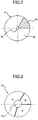
- FIG. 2 is a plan view schematically depicting an example configuration of the optical path switching plate 3.
- the optical path switching plate 3 is formed by, as illustrated in FIG. 2 , a rotation disk for an optical path time division that has a reflection region 3a and a transparent region 3b that are divided in the rotational direction.
- the optical path switching plate 3 is arranged so that the plate surface is inclined with respect to a light axis of laser light of blue component output from the light source unit 1 (here, 45 degrees with respect to the light axis).
- the optical path switching plate 3 is, as illustrated in FIG. 1 , rotationally driven around a rotation driving axis 4a by a stepping motor 4 as an example of a driving source.
- a reflection film is provided on a side of a plate surface, on which laser light of blue component is irradiated.
- an antireflection film is provided on a side of a plate surface, which is irradiated with laser light of blue component.
- Laser light of blue component passing through the transparent region 3b of the optical path switching plate 3 is guided to a phosphor wheel 5 that is an example of a wavelength change member by a condenser lens 11, a reflection mirror 12, a dichroic mirror 9, and a condenser lens 14.
- the condenser lens 11 has a function of condensing laser light of blue component transmitted by the transparent region 3b and converting it into a parallel light flux.
- the dichroic mirror 9 has a function of transmitting light of blue component and guiding it to the phosphor wheel 5, and a function of reflecting fluorescence of a color component other than blue component and guiding it to a color component switching plate 10.
- the condenser lens 14 has a function of condensing a parallel light flux onto the phosphor wheel 5 in a spot like form, and a function of condensing fluorescence from the phosphor wheel 5 and converting it into a parallel light flux.
- the phosphor wheel 5 is formed by a rotation disk, and rotationally driven around a rotational driving axis 6a by a stepping motor 6 that is an example of a driving source.
- a phosphor film 5b is applied, which when being irradiated with laser light of blue component emitted from the light source unit 1, generates fluorescence including a green component (G) and a red component (R) that are different from blue component (B).
- a phosphor film that generates fluorescence of a yellow component (Y) of 450 nm or more and 750 nm or less, including a red component of a wavelength region of 580 nm or more and 750 nm or less and a green component of 450 nm or more and 600 nm or less, can be used.
- a phosphor material of the phosphor film 5b for example, a mixture of a phosphor material that is excited by irradiation of laser light of blue component and generates fluorescence of green component, and a material that is excited in the same way as above and generates fluorescence of red component (a phosphor material that generates yellow fluorescence) can be used, but is not limited to.
- a phosphor material having a phosphor distribution characteristic extending over from a wavelength region of green component and a wavelength region of red component can be used.
- FIG. 3 is a plan view schematically depicting an example configuration of the color component switching plate 10.
- the color component switching plate 10 is formed by a rotation disk, and is rotationally driven in a rotational direction around the rotation driving axis 15a by a stepping motor 15 that is an example of a driving source.
- the color component switching plate 10 is formed, as illustrated in FIG. 3 , by a rotation disk for a color component time division that has a first region (B) that transmits light of blue component in the rotational direction (in this example, a counterclockwise direction), a second region (G) that transmits fluorescence of green component and absorbs or reflects fluorescence of red component, and a third region (R) that transmits fluorescence of red component and absorbs or reflects fluorescence of green component, divided in the rotational direction and formed.
- Blue component transmission region of the color component switching plate 10 (i.e. the first region (B)) can be formed by a transparent glass plate or a notch portion.
- the first region may be formed by a filter that transmits only a specific wavelength band including the wavelength band of blue component. By using a filter, by changing shade a color reproduction range can be adjusted.
- red component is cut by passing through the second region (G) of the color component switching plate 10, and thereby light of only green component passes through the color component switching plate 10 and is guided to a light tunnel 17 that is an example of the light output unit.
- green component is cut by passing through the third region (R) of the color component switching plate 10, and thereby light of only red component passes through the color component switching plate 10 and is guided to the light tunnel 17.
- FIG. 4 is a cross-sectional view depicting an example configuration of the reflection diffusion plate 8 according to the first embodiment.
- a light transmission diffusion layer 8a that transmits and diffuses laser light L of blue component is formed on a base material 8b on which a mirror surface that is an example of the light reflection surface is formed.
- a light diffusion surface is formed on an input surface side of a plate-like light transmission member, and on the light diffusion surface an antireflection film is coated.
- the light transmission diffusion layer 8a has a function of converting input laser light L of blue component into diffusion light to remove coherency.
- the mirror surface on the base material 8b according to the first embodiment reflects light of wide wavelength range, but a dichroic mirror that reflects a part of wavelength band and transmits other wavelength band may be employed.
- FIG. 5 is an explanation diagram depicting light diffused by the reflection diffusion plate 8.
- Laser light L entering the reflection diffusion plate 8 is diffused on a diffusion surface of the light transmission diffusion layer 8a of the reflection diffusion plate 8, to become first diffusion light fluxes L 1 , L 2 , and pass through the light transmission diffusion layer 8a.
- the first diffusion lights L 1 , L 2 are reflected on a mirror surface on the base material 8b of the reflection diffusion plate 8, and pass through the light transmission diffusion layer 8a again and pass the diffusion surface.
- the first diffusion lights L 1 , L 2 are diffused again, respectively, to become second diffusion lights L 11 , L 12 , L 21 , L 22 .
- FIG. 5 an explanation is provided with an example illustrating with a few lights, but actually an infinite number of lights exist, and each light is diffused, to be a uniform light flux.
- a reflection diffusion member such as the reflection diffusion plate 8
- diffusion shaping can be performed twice on a single diffusion surface, and high diffusion performance for laser light L can be obtained with the single diffusion surface.
- a light transmissive material is used for the light diffusion member, in order to perform diffusion shaping twice, two diffusion surfaces are required. Therefore, there is an advantage that by using the reflection diffusion member as in the first embodiment, high diffusion performance can be obtained easily.
- the reflection diffusion plate 8 of the first embodiment transmits laser light and a diffusing light transmission diffusion layer 8a is formed on the light reflection surface, the light reflection surface can be formed as a plane, a reflection coating can be applied easily, and high reflectance can be obtained.
- the reflection coating can be formed by coating with a dielectric multilayer film or a metallic film,
- the light tunnel 17 has a function of reducing light quantity unevenness. Instead of the light tunnel 17, another member such as a fly eye lens may be used. Light guided to the light tunnel 17 is guided by the light tunnel and emitted to the outside of the light irradiation device.
- an absorption member 19 that is a laser light attenuation member which is an example of a laser light leakage prevention means for preventing the laser light L from leaking to the outside of the device remaining in an undiffused state is arranged.
- the absorption member 19 absorbs at least blue component by a predetermined amount or more. For example, a member on which black and nonreflective paint is applied can be used.
- a light shielding member for simply shielding laser light L of blue component may be used.
- the light shielding member the case itself of the light irradiation device may be used, or the light shielding member may be a member different from the case.
- a diffusion plate 22 that is an example of a laser light diffusion member for diffusing laser light L may be used as the laser light leakage prevention means.
- the diffusion plate 22 has a light transmittivity.
- a diffusion surface is provided on a surface side which is irradiated with laser light L, and an antireflection film is formed on a side which laser light L enters.
- a laser light leakage prevention means such as the absorption member 19 or the diffusion member 22 cannot be arranged at a destination to which laser light L goes straight.
- the laser light leakage prevention means obstructs the output optical path.
- a laser light leakage prevention means such as the absorption member 19 or the diffusion member 22 can be arranged at a destination to which laser light L goes straight. Therefore, on an occurrence of the event that due to a breakage or a drop-off of the reflection diffusion plate 8, laser light L from the light source unit 1 goes straight remaining in a non-diffused state at the light diffusion position according to the reflection diffusion plate 8 (i.e.
- the laser light leakage prevention means can surely prevent the laser light L remaining in the non-diffused state from being emitted to the outside from a part other than the light tunnel 17 (gap in the case, a ventilation hole or the like).
- the reflection diffusion plate 8 such as the first embodiment, in addition to reduction of a number of components and low cost, space-saving can be achieved, and a small-size light irradiation device can be enabled.
- FIG. 7 is a schematic diagram depicting an example of a projector using the light irradiation device according to the first embodiment.
- Light passing through the light tunnel 17 of the above-described light irradiation device is made to be a parallel light flux by a condenser lens 25 configuring an illumination optical system, thereafter the light is reflected by reflection mirrors 26, 27 configuring the illumination optical system, and is guided to an image formation panel 13 that is an example of an image formation member.
- the image formation panel 13 is controlled by a publicly known image formation unit (not illustrated), light of each color component is reflected by the image formation panel 13, and emitted to a screen S via a projection lens unit 28 configuring the illumination optical system. Therefore, a color image is enlarged and displayed on the screen S.
- an image formation panel 13 a panel of a reflection type that forms an image in response to modulation signals is exemplified. But a panel of a transmission type may be used.
- the light tunnel 17 is a representative example of a light quantity uniformizing means.
- a projection lens unit 28 is a representative example of a projection optical system.
- respective optical components arranged on the optical path between the color component switching plate 10 and the projection lens unit 28 are stored in a projection system case 29.
- Components between the light source unit 1 and the condenser lens 16 are stored in an illumination system case 20.
- a connection unit between the projection system case 29 and the illumination system case 20 has a configuration that is sealed so that light does not leak to the outside.
- the illumination case 20 and the projection case 29 are formed separately. However, not limited to this, the illumination system case 20 and the projection system case 29 may be formed integrally as necessary. In the configuration illustrated in FIG. 7 , a part of the illumination system case 20 existing at a destination, to which laser light L goes straight at the light diffusion position according to the reflection diffusion plate 8, serves a function as the laser light leaking prevention means that the absorption member 19 has.
- FIG. 8 is a schematic diagram depicting an example configuration of a part of the light irradiation device according to the variation.
- a photo sensor 23 that is an example of a laser light detection means for detecting laser light L of blue component which goes straight at a light diffusion position according to the reflection diffusion plate 8 (i.e. installation position of the reflection diffusion plate 8). Because the laser light detection means only has to detect laser light, not limited to the photo sensor 23, but, for example, the laser light detection means may detect change in temperature by using a temperature detection means, such as a thermistor.
- the photo sensor 23 is arranged between the reflection diffusion plate 8 and the absorption member 19.
- FIG. 9 is a flowchart for explaining an example of an operation according to the variation.
- step S1 When a laser diode 1a of the light source unit 1 is driven to output laser light L of blue component (step S1), in a situation where an abnormality such as a drop-off or breakage of the reflection diffusion plate 8 does not occur, laser light L of blue component is properly reflected and diffused by the reflection diffusion plate 8, and the photo sensor 23 is not radiated with laser light L (step S2: NO).
- step S2 when an abnormality that the reflection diffusion plate 8 is broken or drops off due to aging degradation, a shock or a vibration from outside, or the like, laser light L goes straight at the light diffusion position according to the reflection diffusion plate 8 and is emitted to the photo sensor 23 (step S2: YES). Then, from the photo sensor 23, a detection confirmation signal indicating detection of laser light L is output (step S3).
- the detection confirmation signal output from the photo sensor 23 is sent to an emergency shutoff circuit 24 that is an example of a laser light stoppage control means.
- the emergency shutoff circuit 24 operates when the detection confirmation signal is received from the photo sensor 23 (step S4), and a power supply to the laser diode 1a is disconnected. Then, the output of laser light from the laser diode 1a of the light source unit 1 stops.
- second embodiment the light irradiation device according to the present invention is used as a light irradiation device of a projector that is an example of an image display apparatus.
- FIG. 10 is a schematic diagram depicting an example configuration of a part of a light irradiation device according to the second embodiment.
- the optical path according to the second embodiment when light of blue component (B) is emitted will be described.
- Laser light L of blue component (B) output from the light source unit 1 is condensed by the condenser lens 1c and focused on approximately one point on the optical path switching plate 3, and reflected in the reflection region 3a on the optical path switching plate 3. Therefore, the light is guided to the reflection diffusion plate 8 through the lens 7, reflected and diffused by the reflection diffusion plate 8, and thereafter, guided to a second dichroic mirror 34.
- the second dichroic mirror 34 has a function of reflecting light of blue component and a function of transmitting fluorescence of a color component other than blue component. Therefore, light of blue component guided to the second dichroic mirror 34 is reflected at the second dichroic mirror 34 and guided to the color component switching plate 35.
- FIG. 11 is a plan view schematically depicting an example configuration of the color component switching plate 35 according to the second embodiment.
- a basic configuration of the color component switching plate 35 according to the second embodiment is the same as in the first embodiment, as illustrated in FIG. 11 , in a rotational direction indicated by an arrow (in this example, a counterclockwise direction), in addition to a first region (B) that transmits light of blue component, a second region (G) that transmits fluorescence of green component and absorbs or reflects fluorescence of red component, and a third region (R) that transmits fluorescence of red component and absorbs or reflects fluorescence of green component, a fourth region (Y) that absorbs or reflects light of blue component are formed on a rotational disk for a color component time division that is formed by dividing in the rotational direction.
- the fourth region (Y) is formed on the rotational direction between the first region (B) and the second region (G).
- Laser light L of blue component (B) output from the light source unit 1 is condensed by the condenser lens 1c and focused on approximately one point on the optical path switching plate 3, and passes through the transparent region 3b on the optical path switching plate 3.
- Laser light L of blue component (B) passing through the transparent region 3b on the optical path switching plate 3 becomes diffusion light when passing through a transmission diffusion plate 31, and thereafter, guided to a first dichroic mirror 33 through a lens 11.
- the first dichroic mirror 33 has a function of transmitting light of blue component and a function of reflecting fluorescence of a color component other than blue component. Therefore, light of blue component guided to the first dichroic mirror 33 passes through the first dichroic mirror 33 and guided to the phosphor wheel 5.
- the reflection diffusion plate 8 even if the event that the reflection diffusion plate 8 is broken or drops off due to aging degradation, a shock or a vibration from outside, or the like, laser light L remaining in a non-diffused state is not emitted from the light tunnel 17 to the outside. Furthermore, in the same way as the first embodiment, because at a destination to which laser light L from the light source unit remaining in a non-diffused state goes straight at the light diffusion position according to the reflection diffusion plate 8 (i.e.
- an absorption member 19 is arranged, the laser light L remaining in the non-diffused state is surely prevented from being emitted to the outside from a part other than the light tunnel 17 (gap in the case, a ventilation hole or the like).
- third embodiment the light irradiation device according to the present invention is used as a light irradiation device of a projector that is an example of an image display apparatus.
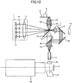
- FIG. 12 is a schematic diagram depicting an example configuration of a part of the light irradiation device according to the third embodiment.
- FIG. 13 is a plan view schematically depicting an example configuration a color component/optical path switching plate 41 according to the third embodiment.
- the color component/optical path switching plate 41 is formed by a rotational disk for an optical path time division having a blue component transparent region 41a, a red component transparent region 41b, a green component transparent region 41c and a yellow component transparent region 41d, divided in a rotational direction indicated by an arrow (in this example, a counterclockwise direction).
- the blue component transparent region can be formed by a transparent glass or a notch. Any of the other regions 41b, 41c, 41d reflect blue component (B).
- Each of the other regions 41b, 41c 41d is formed by a dichroic mirror that transmits only red component (R), green component (G) or yellow component.
- the color component/optical path switching plate 41 according to the third embodiment is equally divided into four regions 41a, 41b, 41c and 41d (segment angle is 90°). However, angles of the respective regions are not limited to this. Depending on color design of a projector that uses the light irradiation device, optimum values for the segment angles may be selected.
- Laser light L of blue component (B) output from the light source unit 1 is condensed by the condenser lens 1c and focused on approximately one point on the color component/optical path switching plate 41.
- the laser light L of blue component (B) guided to the color component/optical path switching plate 41 passes through the blue component transparent region 41a on the color component/optical path switching plate 41, and thereafter, guided to the reflection diffusion plate 8 through the lens 7, and reflected and diffused by the reflection diffusion plate 8, and thereafter, reflected at the reflection mirror 42 and guided to the dichroic mirror 43.
- the dichroic mirror 43 has a function of reflecting light of blue component and a function of transmitting fluorescence of a color component other than blue component. Therefore, light of blue component guided to the dichroic mirror 43 is reflected at the dichroic mirror 43 and guided to the light tunnel 17 via the lens 16. Then, light of blue component is injected into the light tunnel 17 and becomes uniform light, and thereafter, injected to the image formation panel 13 through the lens 25 and the mirror 27, and projected onto a screen through the projection lens unit 28.
- Laser light L of blue component (B) output from the light source unit 1 is condensed by the condenser lens 1c and focused on approximately one point on the color component/optical path switching plate 41, and reflected at the red component transparent region 41b on the color component/optical path switching plate 41, and guided to the phosphor wheel 5 passing through a lens 44, a transmission diffusion plate 45 and a lens 46.
- the transmission diffusion plate 45 by arranging the transmission diffusion plate 45, in the same way as in the second embodiment, laser light L from the light source unit 1 is diffused by the transmission diffusion plate 31, and then, emitted to the optical components of the subsequent stage, such as the lens 46, the phosphor wheel 5 or the like. Therefore, compared with the case where laser light L in a non-diffused state is directly emitted, a breakage or the like of the lens 46 or the phosphor wheel 5 due to a rise in temperature by focusing light on one point can be prevented.
- the reflection diffusion plate 8 even if the event that the reflection diffusion plate 8 is broken or drops off due to aging degradation, a shock or a vibration from outside, or the like, laser light L remaining in a non-diffused state is not emitted from the light tunnel 17 to the outside. Furthermore, in the same way as the first and second embodiments, because at a destination to which laser light L from the light source unit remaining in a non-diffused state goes straight at the light diffusion position according to the reflection diffusion plate 8 (i.e.
- an absorption member 19 is arranged, the laser light L remaining in the non-diffused state is surely prevented from being emitted to the outside from a part other than the light tunnel 17 (gap in the case, a ventilation hole or the like).
- the color component switching plate 10, 35 which is provided in the first or second embodiment is not provided. This is because the color component/optical path switching plate 41 has a function of the color component switching plate 10, 35. Therefore, in addition to reduction of a number of components and cost reduction, space saving can be achieved and a small sized light irradiation device can be provided. Furthermore, in the configuration, as in the first and second embodiments, where the optical path switching plate 3 and the color component switching plate 10, 35 are provided separately, a rotation synchronization control between the optical path switching plate 3 and the color component switching plate 10, 35 is required. However, according to the third embodiment, such a rotation synchronization control becomes unnecessary, and a control can be simplified.
- the reflection diffusion plate 8 and the reflection mirror 42 may be exchanged and arranged.
- the installation position of the absorption member 19 may be changed.
- the reflection diffusion plate 8 not only the reflection diffusion plate 8, but also the reflection mirror 42 may be formed by a reflection diffusion plate.
- a reflection diffusion plate for light of blue component, greater diffusion effect can be obtained.
- a laser light leaking prevention means such as the absorption member 19 is not necessary to be arranged at a destination to which the light goes straight due to the drop-off or the like of the second reflection diffusion plate.
- reflection surfaces of the red component transparent region 41b, the green component transparent region 41c, and the yellow component transparent region 41d on the color component/optical path switching plate 41 may serve as reflection diffusion surfaces. Therefore, because the transmission diffusion plate 45 becomes unnecessary, the number of components is reduced, cost reduction and size reduction of the light irradiation device can be achieved.
- first reference example a reference example of a light irradiation device used in a projector that is an example of an image display apparatus
- FIG. 14 is a schematic diagram depicting an example configuration of a part of a light irradiation device according to the first reference example.
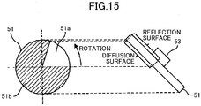
- FIG. 15 is a plan view schematically depicting an example configuration of an optical path switching plate 51 according to the first reference example.
- the optical path switching plate 51 according to the first reference example is formed by a rotation disk for an optical path time division having a reflection diffusion region 51a and a transmission region 51b divided in a rotational direction.
- the reflection diffusion region 51a according to the first reference example is formed of the same reflection diffusion member as the above-described reflection diffusion plate 8.
- the reflection diffusion plate 8 provided in the second embodiment can be omitted, and instead of the reflection diffusion plate 8 a general reflection mirror 52 that is not provided with the light diffusion function is installed. Needless to say, the reflection diffusion plate 8 may be arranged instead of the reflection mirror 52. In this case, for light of blue component, greater diffusion effect can be obtained.
- a reflection diffusion part irradiated with laser light L of blue component temporally changes according to a rotation of the optical path switching plate 51.
- an illuminance distribution on the screen varies with time.
- unevenness of a projection image is averaged temporally, and a uniform image can be obtained. Therefore, compared with the case where the same part is always irradiated with laser light L of blue component such as the reflection diffusion plate 8 in the second embodiment, an effect of uniformizing an image can be enhanced.
- an illumination optical system which is small and has high efficiency while obtaining a uniform image, can be provided.
- second reference example a light irradiation device used in a projector that is an example of an image display apparatus
- FIG. 16 is a schematic diagram depicting an example configuration of a part of a light irradiation device according to the second reference example.
- FIG. 17 is a plan view schematically depicting an example configuration of an optical path switching plate 61 according to the second reference example.
- the optical path switching plate 61 according to the second reference example is formed by a rotation disk for an optical path time division having a reflection diffusion region 61a and a transmission diffusion region 61b divided in a rotational direction.
- the reflection diffusion region 51a according to the second reference example is formed of the same reflection diffusion member as the above-described reflection diffusion plate 8.
- the transmission diffusion region 61b according to the second reference example is formed of the same transmission diffusion member as the above-described transmission diffusion plate 31.
- the transmission diffusion region 61b in the optical path switching plate 61 according to the second reference example is formed of a transmission diffusion member, the transmission diffusion plate 31 provided in the first reference example can be omitted. Therefore, the number of components is reduced, cost reduction and size reduction of the light irradiation device can be achieved.
- diffusion surfaces of the reflection diffusion region 61a and the transmission diffusion region 61b in the optical path switching plate 61 are arranged on the same surface side.
- the optical path switching plate 61 provided with the reflection diffusion region 61a and the transmission diffusion region 61b may be manufactured by preparing a plate in which one surface is a diffusion surface and the other surface is subjected to anti-reflection (AR) coating or reflection coating, cutting the plate which is subjected to coating, and bonding the plates with each other.
- AR anti-reflection
- a front and a back of the transmission diffusion surface can be arbitrarily selected.
- any of the reference diffusion members that convert incident light into diffusion light and reflect the light may have a configuration in which a light transmission diffusion layer for transmitting and diffusing light is formed on a light reflection surface, as illustrated in FIGs. 4 and 5 .
- Aspect A is, in a light irradiation device that includes a laser light source such as a laser diode 1a for emitting laser light L; and a light diffusion member for converting the laser light L emitted by the laser light source into diffusion light, and emits light based on the laser light emitted by the laser light source from a light output unit such as a light tunnel 17 to the outside via an output optical path or two or more output optical paths including an optical path through which the diffusion light converted by the light diffusion member passes, the light diffusion member is a diffusion optical path changing member such as a reflection diffusion plate 8 that converts the laser light emitted by the laser light source into diffusion light and changes an optical path, the output optical path does not include an optical path on which laser light emitted toward the diffusion optical path changing member goes straight at a light diffusion position according to the diffusion optical path changing member and goes toward the light output unit.
- a laser light source such as a laser diode 1a for emitting laser light L
- a light diffusion member for converting the laser light
- the diffusion optical path changing member or light diffusion member arranged on the optical path of laser light drops off or is broken and laser light remaining in a non-diffused state goes straight at the light diffusion position according to the diffusion optical path changing member, the laser light does not goes to the light output unit. Therefore, laser light can be prevented from emitting directly from the light output unit to the outside.
- Aspect B is, in the above-described Aspect A, at a destination to which laser light emitted toward the diffusion optical path changing member goes straight at the light diffusion position according to the diffusion optical path changing member, a laser light leaking prevention means such as an absorption member 19, a diffusion plate 22, or an illumination system case 20, that prevents the laser light from leaking to the outside of the device remaining in a non-diffused state is included.
- a laser light leaking prevention means such as an absorption member 19, a diffusion plate 22, or an illumination system case 20, that prevents the laser light from leaking to the outside of the device remaining in a non-diffused state is included.
- the laser light leaking prevention means is a laser light attenuation member such as an absorption member 19 that attenuates the laser light.
- high-intensity laser light can be prevented from leaking to the outside.
- the laser light leaking prevention means is a laser light diffusion member such as a diffusion plate 22 that diffused the laser light.
- Aspect E includes, in any one of the above-described Aspects A through D, a laser light detection means such as a photo sensor 23 that detects laser light which goes straight at the light diffusion position according to the diffusion optical path changing member.
- a laser light detection means such as a photo sensor 23 that detects laser light which goes straight at the light diffusion position according to the diffusion optical path changing member.
- the diffusion optical path changing member arranged on the optical path of laser light is drops-off or is broken, and laser light remaining in a non-diffused state goes straight at the light diffusion position according to the diffusion optical path changing member, the light can be detected. Therefore, a handling operation for stopping the output of the laser light source or reporting to a user can be performed.
- Aspect F uses, in the above-described Aspect E, a temperature detection means as the laser light detection means.
- Aspect G includes, in the above-described Aspect E or F, a laser light stop controlling means such as an emergency shut-off circuit 24 that stops emission of laser light of the laser light source when the laser light detection means detects laser light.
- a laser light stop controlling means such as an emergency shut-off circuit 24 that stops emission of laser light of the laser light source when the laser light detection means detects laser light.
- the diffusion optical path changing member is formed of a reflection diffusion member that converts laser light emitted by the laser light source into diffusion light and reflects the laser light.
- the diffusion optical path changing means can be formed more easily than a member that changes an optical path by refracting laser light.
- the reflection diffusion member is a member in which a light transmission diffusion layer that transmits and diffuses the laser light is formed on a light reflection surface.
- Aspect J includes, in the above-described Aspect I, a wavelength conversion member such as a phosphor wheel 5 that receives laser light from the laser light source and thereby emits light of another wavelength band different from the laser light; a first output optical path for reflecting and diffusing laser light emitted by the laser light source by the reflection diffusion member and directing the laser light toward the light output unit without going through the wavelength conversion member; and a second output optical path for irradiating the wavelength conversion member with laser light emitted by the laser light source and directing light of another wavelength band emitted from the wavelength conversion member toward the light output unit.
- a wavelength conversion member such as a phosphor wheel 5 that receives laser light from the laser light source and thereby emits light of another wavelength band different from the laser light
- a first output optical path for reflecting and diffusing laser light emitted by the laser light source by the reflection diffusion member and directing the laser light toward the light output unit without going through the wavelength conversion member
- a second output optical path for irradiating the wavelength conversion
- the Aspect J because in a light irradiation device that emits a plurality of wavelength bands, laser light from the laser light source can be emitted as diffusion light without performing a wavelength conversion, a configuration can be made simple.
- the light diffusion member arranged on an optical path is light transmissive, if the light diffusion member drops off or is broken, laser light is emitted from the light output unit to the outside remaining in a non-diffused state.
- the light diffusion member arranged on the optical path is a diffusion optical path changing member, emission of laser light from the light output unit to the outside remaining in a non-diffused state can be suppressed.
- Aspect K is an image display apparatus such as a projector including the light irradiation device according to any one of the above-described Aspects A through J; an illumination optical system such as a condenser lens 25, or reflection mirror 26, 27 that transfers light emitted from the light irradiation device to an image formation member such as an image formation panel 13; and a projection optical system such as a projection lens unit 28 that enlarges and projects an image formed in the image formation member.
- an illumination optical system such as a condenser lens 25, or reflection mirror 26, 27 that transfers light emitted from the light irradiation device to an image formation member such as an image formation panel 13
- a projection optical system such as a projection lens unit 28 that enlarges and projects an image formed in the image formation member.
Landscapes
- Physics & Mathematics (AREA)
- General Physics & Mathematics (AREA)
- Engineering & Computer Science (AREA)
- Optics & Photonics (AREA)
- Multimedia (AREA)
- Signal Processing (AREA)
- Computer Security & Cryptography (AREA)
- Spectroscopy & Molecular Physics (AREA)
- Astronomy & Astrophysics (AREA)
- Projection Apparatus (AREA)
- Arrangement Of Elements, Cooling, Sealing, Or The Like Of Lighting Devices (AREA)
- Non-Portable Lighting Devices Or Systems Thereof (AREA)
- Transforming Electric Information Into Light Information (AREA)
Abstract
Description
- 0001 The disclosures herein generally relate to a light irradiation device for irradiating laser light from a laser light source or light based on the laser light to the outside from a light output unit and an image display apparatus equipped with the same.
- 0002 A light irradiation device irradiating laser light or light based on the laser light to the outside from a light output unit is used for an image display apparatus such as a projector for projecting an image of a screen of a personal computer, a video image, or further, image data stored in a memory card or the like. The projector generally collects light emitted from a light irradiation device at an image formation member such as a micro mirror display element known as a digital micro-mirror device (DMD) or a liquid crystal plate, and displays an image on a screen. Conventionally, light irradiation devices each having high-intensity discharge lamps serving as light sources were mainly used for such projectors. However, recently, a projector using a laser light source such as a laser diode (LD) emitting laser light for a light source has been proposed (for example, Patent Document 1).
- 0003 Regarding light irradiation devices equipped with laser light sources, in IEC 60825, that is the international standard of the International Electrotechnical Commission (IEC) or in JIS C6802:2005 that is the Japanese standard, laser products are classified, and guidelines to be followed by a manufacturer or a user are established for each class so as to enhance the safety of the laser products.
- 0004 In a light irradiation device equipped with a laser light source, generally, a light diffusion member for diffusing laser light is provided on an optical path of laser light in order to prevent laser light emitted from a laser light source being directly irradiated to the outside. Then, light based on the laser light emitted from the laser light source is irradiated to the outside from a light output unit via an output optical path or two or more output optical paths including an optical path, through which diffusion light converted by the light diffusion member passes. As a result of laser light passing through the light diffusion member to be converted into diffusion light and emitted, safety is confirmed to be ensured even if the laser light source emits laser light with high intensity.
- 0005 [PTL 1] Japanese Unexamined Patent Application Publication No.
2013-195838 - 0006 In most of the conventional light irradiation devices, the light diffusion member provided on an optical path of a laser light is light transmissive. In such a light irradiation device, for example, on an occurrence of an event that the light irradiation device falls and is severely damaged or the like, and that the light diffusion member falls or is broken, laser light from the laser light source may pass a light diffusion position according to the light diffusion member in a non-diffused state. In this case, a problem occurs that laser light emitted from the laser light source can be directly irradiated to the outside.
- 0007 The present invention is made in consideration of the above-described problem, and an object is to provide a light irradiation device, in which even when a light diffusion member provided on an optical path of laser light falls or is broken and laser light passes a light diffusion position according to the light diffusion member in a non-diffused state, laser light can be prevented from being directly irradiated to the outside from the light output unit, and an image display apparatus equipped with the same.
- 0008 According to an aspect of the present invention, a light irradiation device includes a laser light source configured to emit laser light; and a light diffusion member configured to convert the laser light into diffusion light. Light based on the laser light is emitted to an outside from a light output unit via an output optical path or two or more output optical paths including an optical path which the diffusion light passes through. The light diffusion member includes a diffusion optical path changing member configured to convert the laser light into the diffusion light and change an optical path. The output optical path does not include an optical path in which laser light emitted toward the diffusion optical path changing member goes straight at a light diffusion position according to the diffusion optical path changing member to go toward the light output unit.
- 0009 According to the present invention, even when a light diffusion member provided on an optical path of laser light falls or is broken and laser light passes a light diffusion position according to the light diffusion member in a non-diffused state, laser light can be prevented from being directly irradiated to the outside from the light output unit.
- 0010
- [
FIG. 1 ]
FIG. 1 is a schematic diagram depicting an example configuration of a part of a light irradiation device according to a first embodiment. - [
FIG. 2 ]
FIG. 2 is a plan view schematically depicting an example configuration of an optical path switching panel in the light irradiation device. - [
FIG. 3 ]
FIG. 3 is a plan view schematically depicting an example configuration of a color component switching panel in the light irradiation device. - [
FIG. 4 ]
FIG. 4 is a cross-sectional diagram depicting an example configuration of a reflection diffusion plate in the first embodiment. - [
FIG. 5 ]
FIG. 5 is an explanation diagram depicting light diffused by the reflection diffusion plate. - [
FIG. 6 ]
FIG. 6 is a schematic diagram depicting an example when a diffusion plate is used instead of a light absorption member as a laser light leakage prevention means. - [
FIG. 7 ]
FIG. 7 is a schematic diagram depicting an example projector using the light irradiation device according to the first embodiment. - [
FIG. 8 ]
FIG. 8 is a schematic diagram depicting an example configuration of a part of a light irradiation device according to a variation. - [
FIG. 9 ]
FIG. 9 is a flowchart for explaining an example of an operation according to the variation. - [
FIG. 10 ]
FIG. 10 is a schematic diagram depicting an example configuration of a part of a light irradiation device according to a second embodiment. - [
FIG. 11 ]
FIG. 11 is a plan view schematically depicting an example configuration of a color component switching panel according to the second embodiment. - [
FIG. 12 ]
FIG. 12 is a schematic diagram depicting an example configuration of a part of a light irradiation device according to a third embodiment. - [
FIG. 13 ]
FIG. 13 is a plan view schematically depicting an example configuration of a color component/optical path switching panel according to the third embodiment. - [
FIG. 14 ]
FIG. 14 is a schematic diagram depicting an example configuration of a part of a light irradiation device according to a first reference example. - [
FIG. 15 ]
FIG. 15 is a plan view schematically depicting an example configuration of an optical path switching panel according to the first reference example. - [
FIG. 16 ]
FIG. 16 is a schematic diagram depicting an example configuration of a part of a light irradiation device according to a second reference example. - [
FIG. 17 ]
FIG. 17 is a plan view schematically depicting an example configuration of an optical path switching panel according to the second reference example. - 0011
- In the following, an embodiment of the present invention (in the following, the present embodiment will be referred to as a "first embodiment") will be described in which a light irradiation device is used for a light irradiation device of a projector that is an example of an image display apparatus.
- 0012
FIG. 1 is a schematic diagram depicting an example configuration of a part of a light irradiation device according to the first embodiment. - 0013 A
light source unit 1, illustrated inFIG. 1 , includes alaser diode 1a that is a laser light source, acoupling lens 1b and acondenser lens 1c. Alaser diode 1a or two ormore laser diodes 1a are arranged in alaser diode holder 2. On a back surface side of thelaser diode holder 2, a heat sink (or a radiator plate) 21 for dissipating heat generated at thelaser diode 1a is provided. A material of theheat sink 21 is a metal such as aluminum or copper. - 0014 Laser light from the
laser diode 1a is condensed by thecoupling lens 1b, and guided to thecondenser lens 1c as a parallel light flux. Thecondenser lens 1c has a function of condensing laser light that has been made to be a parallel light flux by thecoupling lens 1b. For thelaser diode 1a in the first embodiment, although a case of a blue laser light source for outputting laser light of a blue component will be described as an example, a laser light source for outputting laser light of a green component or laser light of a red component may be used. Moreover, instead of the laser diode, another laser light source may be used. - 0015 Laser light of blue component condensed by the
condenser lens 1c is guided to an opticalpath switching plate 3 that is an example of the optical path switching member. A spot size of laser light irradiated on the opticalpath switching plate 3 is properly defined so as to prevent color mixture or the like. - 0016
FIG. 2 is a plan view schematically depicting an example configuration of the opticalpath switching plate 3. - 0017 The optical
path switching plate 3 is formed by, as illustrated inFIG. 2 , a rotation disk for an optical path time division that has areflection region 3a and atransparent region 3b that are divided in the rotational direction. The opticalpath switching plate 3 is arranged so that the plate surface is inclined with respect to a light axis of laser light of blue component output from the light source unit 1 (here, 45 degrees with respect to the light axis). The opticalpath switching plate 3 is, as illustrated inFIG. 1 , rotationally driven around arotation driving axis 4a by a steppingmotor 4 as an example of a driving source. - 0018 In the
reflection region 3a of the opticalpath switching plate 3, a reflection film is provided on a side of a plate surface, on which laser light of blue component is irradiated. Moreover, in thetransparent region 3b of the opticalpath switching plate 3, an antireflection film is provided on a side of a plate surface, which is irradiated with laser light of blue component. - 0019 Laser light of blue component passing through the
transparent region 3b of the opticalpath switching plate 3 is guided to aphosphor wheel 5 that is an example of a wavelength change member by acondenser lens 11, areflection mirror 12, adichroic mirror 9, and acondenser lens 14. Thecondenser lens 11 has a function of condensing laser light of blue component transmitted by thetransparent region 3b and converting it into a parallel light flux. Thedichroic mirror 9 has a function of transmitting light of blue component and guiding it to thephosphor wheel 5, and a function of reflecting fluorescence of a color component other than blue component and guiding it to a colorcomponent switching plate 10. Thecondenser lens 14 has a function of condensing a parallel light flux onto thephosphor wheel 5 in a spot like form, and a function of condensing fluorescence from thephosphor wheel 5 and converting it into a parallel light flux. - 0020 The
phosphor wheel 5 is formed by a rotation disk, and rotationally driven around arotational driving axis 6a by a steppingmotor 6 that is an example of a driving source. On thephosphor wheel 5, aphosphor film 5b is applied, which when being irradiated with laser light of blue component emitted from thelight source unit 1, generates fluorescence including a green component (G) and a red component (R) that are different from blue component (B). For thephosphor film 5b, as described above, for example, a phosphor film that generates fluorescence of a yellow component (Y) of 450 nm or more and 750 nm or less, including a red component of a wavelength region of 580 nm or more and 750 nm or less and a green component of 450 nm or more and 600 nm or less, can be used. - 0021 According to rotation of the
phosphor wheel 5, laser light is prevented from being irradiating continuously on the same part, and degradation of thephosphor film 5b is prevented. For a phosphor material of thephosphor film 5b, for example, a mixture of a phosphor material that is excited by irradiation of laser light of blue component and generates fluorescence of green component, and a material that is excited in the same way as above and generates fluorescence of red component (a phosphor material that generates yellow fluorescence) can be used, but is not limited to. For example, a phosphor material having a phosphor distribution characteristic extending over from a wavelength region of green component and a wavelength region of red component can be used. - 0022 Laser light of blue component passing through the
transparent region 3b of the opticalpath switching plate 3, passes through thedichroic mirror 9 and is emitted to thephosphor wheel 5, and thereby thephosphor wheel 5 generates fluorescence including green component and red component. When fluorescence of green component and red component, generated in this way, is input to thedichroic mirror 9, the fluorescence is reflected at thedichroic mirror 9, condensed by acondenser lens 16, and guided to the colorcomponent switching plate 10. - 0023
FIG. 3 is a plan view schematically depicting an example configuration of the colorcomponent switching plate 10. - 0024 The color
component switching plate 10 is formed by a rotation disk, and is rotationally driven in a rotational direction around therotation driving axis 15a by a steppingmotor 15 that is an example of a driving source. The colorcomponent switching plate 10 is formed, as illustrated inFIG. 3 , by a rotation disk for a color component time division that has a first region (B) that transmits light of blue component in the rotational direction (in this example, a counterclockwise direction), a second region (G) that transmits fluorescence of green component and absorbs or reflects fluorescence of red component, and a third region (R) that transmits fluorescence of red component and absorbs or reflects fluorescence of green component, divided in the rotational direction and formed. Blue component transmission region of the color component switching plate 10 (i.e. the first region (B)) can be formed by a transparent glass plate or a notch portion. However, the first region may be formed by a filter that transmits only a specific wavelength band including the wavelength band of blue component. By using a filter, by changing shade a color
reproduction range can be adjusted. - 0025 In fluorescence including green component and red component that is output from
phosphor wheel 5 and guided to the colorcomponent switching plate 10, red component is cut by passing through the second region (G) of the colorcomponent switching plate 10, and thereby light of only green component passes through the colorcomponent switching plate 10 and is guided to alight tunnel 17 that is an example of the light output unit. Moreover, in fluorescence including green component and red component guided to the colorcomponent switching plate 10, green component is cut by passing through the third region (R) of the colorcomponent switching plate 10, and thereby light of only red component passes through the colorcomponent switching plate 10 and is guided to thelight tunnel 17. - 0026
FIG. 4 is a cross-sectional view depicting an example configuration of thereflection diffusion plate 8 according to the first embodiment. - 0027 Laser light of blue component reflected in the
reflection region 3a of the opticalpath switching plate 3 is converted by thecondenser lens 7 into a parallel light flux, and reflected by thereflection diffusion plate 8 forming the reflection diffusion member that is an example of a diffusion optical path change member. In thereflection diffusion plate 8 according to the first embodiment, as illustrated inFIG. 4 , a lighttransmission diffusion layer 8a that transmits and diffuses laser light L of blue component is formed on abase material 8b on which a mirror surface that is an example of the light reflection surface is formed. In the lighttransmission diffusion layer 8a, a light diffusion surface is formed on an input surface side of a plate-like light transmission member, and on the light diffusion surface an antireflection film is coated. The lighttransmission diffusion layer 8a has a function of converting input laser light L of blue component into diffusion light to remove coherency. The mirror surface on thebase material 8b according to the first embodiment reflects light of wide wavelength range, but a dichroic mirror that reflects a part of wavelength band and transmits other wavelength band may be employed. - 0028
FIG. 5 is an explanation diagram depicting light diffused by thereflection diffusion plate 8. - 0029 Laser light L entering the
reflection diffusion plate 8 is diffused on a diffusion surface of the lighttransmission diffusion layer 8a of thereflection diffusion plate 8, to become first diffusion light fluxes L1, L2, and pass through the lighttransmission diffusion layer 8a. Afterwards, the first diffusion lights L1, L2 are reflected on a mirror surface on thebase material 8b of thereflection diffusion plate 8, and pass through the lighttransmission diffusion layer 8a again and pass the diffusion surface. At this time, the first diffusion lights L1, L2 are diffused again, respectively, to become second diffusion lights L11, L12, L21, L22. InFIG. 5 , an explanation is provided with an example illustrating with a few lights, but actually an infinite number of lights exist, and each light is diffused, to be a uniform light flux. - 0030 In this way, by using a reflection diffusion member, such as the
reflection diffusion plate 8, for a light diffusion member for diffusing laser light L, diffusion shaping can be performed twice on a single diffusion surface, and high diffusion performance for laser light L can be obtained with the single diffusion surface. When a light transmissive material is used for the light diffusion member, in order to perform diffusion shaping twice, two diffusion surfaces are required. Therefore, there is an advantage that by using the reflection diffusion member as in the first embodiment, high diffusion performance can be obtained easily. - 0031 Because the
reflection diffusion plate 8 of the first embodiment transmits laser light and a diffusing lighttransmission diffusion layer 8a is formed on the light reflection surface, the light reflection surface can be formed as a plane, a reflection coating can be applied easily, and high reflectance can be obtained. The reflection coating can be formed by coating with a dielectric multilayer film or a metallic film, - 0032 Laser light (diffusion light) L' of blue component which is reflected a diffused by the
reflection diffusion plate 8 is guided to thedichroic mirror 9. Because thedichroic mirror 9 has, as described above, a function of transmitting light of blue component, the light reflected and diffused by thereflection diffusion plate 8 passes through thedichroic mirror 9, is condensed by thecondenser lens 16, and thereafter, is guided to the colorcomponent switching plate 10. The laser light of blue component guided to the colorcomponent switching plate 10 in this way passes through the first region of the colorcomponent switching plate 10 and guided to thelight tunnel 17. - 0033 The
light tunnel 17 has a function of reducing light quantity unevenness. Instead of thelight tunnel 17, another member such as a fly eye lens may be used. Light guided to thelight tunnel 17 is guided by the light tunnel and emitted to the outside of the light irradiation device. - 0034 In the first embodiment, as illustrated in
FIG. 1 , at a destination to which laser light L of blue component emitted toward thereflection diffusion plate 8 goes straight at the light diffusion position according to the reflection diffusion plate 8 (i.e. installation position of the reflection diffusion plate 8), anabsorption member 19 that is a laser light attenuation member which is an example of a laser light leakage prevention means for preventing the laser light L from leaking to the outside of the device remaining in an undiffused state is arranged. Theabsorption member 19 absorbs at least blue component by a predetermined amount or more. For example, a member on which black and nonreflective paint is applied can be used. - 0035 For the laser light leakage prevention means, not limited to the absorption means 19, a light shielding member for simply shielding laser light L of blue component may be used. As the light shielding member, the case itself of the light irradiation device may be used, or the light shielding member may be a member different from the case.
- 0036 Moreover, as illustrated in
FIG. 6 , as the laser light leakage prevention means, adiffusion plate 22 that is an example of a laser light diffusion member for diffusing laser light L may be used. Thediffusion plate 22 has a light transmittivity. A diffusion surface is provided on a surface side which is irradiated with laser light L, and an antireflection film is formed on a side which laser light L enters. By arranging thediffusion plate 22, described as above, when laser light L passes through thediffusion plate 22, coherency is removed by an action of diffusion of thediffusion plate 22. Therefore, even if laser light (diffusion light) passing through thediffusion plate 22 leaks to the outside, there is no safety problem. - 0037 On an occurrence of an event that the
reflection diffusion plate 8 is broken or drops off due to aging degradation, a shock or a vibration from outside, or the like, an event that laser light L from thelight source unit 1 goes straight remaining in a non-diffused state at the light diffusion position according to the reflection diffusion plate 8 (i.e. installation position of the reflection diffusion plate 8) can occur. However, in the first embodiment, there is not an output optical path in which laser light L from thelight source unit 1 goes straight at the light diffusion position according to the reflection diffusion plate 8 (i.e. installation position of the reflection diffusion plate 8) to thelight tunnel 17. Therefore, according to the first embodiment, even if the event that thereflection diffusion plate 8 is broken or drops off due to aging degradation, a shock or a vibration from outside, or the like, laser light L remaining in a non-diffused state is not emitted from thelight tunnel 17 to the outside. - 0038 Moreover, in a configuration where there is an output optical path in which laser light L from the
light source unit 1 goes straight at the light diffusion position according to the reflection diffusion plate 8 (i.e. installation position of the reflection diffusion plate 8) to thelight tunnel 17, a laser light leakage prevention means such as theabsorption member 19 or thediffusion member 22 cannot be arranged at a destination to which laser light L goes straight. When such a laser light leakage prevention means is arranged, the laser light leakage prevention means obstructs the output optical path. - 0039 In contrast, in the first embodiment, because there is not an output optical path in which laser light L from the
light source unit 1 goes straight at the light diffusion position according to the reflection diffusion plate 8 (i.e. installation position of the reflection diffusion plate 8) to thelight tunnel 17, a laser light leakage prevention means such as theabsorption member 19 or thediffusion member 22 can be arranged at a destination to which laser light L goes straight. Therefore, on an occurrence of the event that due to a breakage or a drop-off of thereflection diffusion plate 8, laser light L from thelight source unit 1 goes straight remaining in a non-diffused state at the light diffusion position according to the reflection diffusion plate 8 (i.e. installation position of the reflection diffusion plate 8), the laser light leakage prevention means can surely prevent the laser light L remaining in the non-diffused state from being emitted to the outside from a part other than the light tunnel 17 (gap in the case, a ventilation hole or the like). - 0040 Moreover, by using the
reflection diffusion plate 8 such as the first embodiment, compared with a case of using a configuration where a transmission diffusion plate and a reflection mirror are combined, in addition to reduction of a number of components and low cost, space-saving can be achieved, and a small-size light irradiation device can be enabled. - 0041 Next, a configuration and operation of a projector that is an example of an image display apparatus installing the light irradiation device according to the first embodiment will be described.
- 0042
FIG. 7 is a schematic diagram depicting an example of a projector using the light irradiation device according to the first embodiment. - 0043 Light passing through the
light tunnel 17 of the above-described light irradiation device is made to be a parallel light flux by acondenser lens 25 configuring an illumination optical system, thereafter the light is reflected by reflection mirrors 26, 27 configuring the illumination optical system, and is guided to animage formation panel 13 that is an example of an image formation member. Theimage formation panel 13 is controlled by a publicly known image formation unit (not illustrated), light of each color component is reflected by theimage formation panel 13, and emitted to a screen S via aprojection lens unit 28 configuring the illumination optical system. Therefore, a color image is enlarged and displayed on the screen S. - 0044 In the first embodiment, as an
image formation panel 13, a panel of a reflection type that forms an image in response to modulation signals is exemplified. But a panel of a transmission type may be used. Thelight tunnel 17 is a representative example of a light quantity uniformizing means. Moreover, aprojection lens unit 28 is a
representative example of a projection optical system. Moreover, respective optical components arranged on the optical path between the colorcomponent switching plate 10 and theprojection lens unit 28 are stored in aprojection system case 29. Components between thelight source unit 1 and thecondenser lens 16 are stored in anillumination system case 20. A connection unit between theprojection system case 29 and theillumination system case 20 has a configuration that is sealed so that light does not leak to the outside. - 0045 In
FIG. 7 , theillumination case 20 and theprojection case 29 are formed separately. However, not limited to this, theillumination system case 20 and theprojection system case 29 may be formed integrally as necessary. In the configuration illustrated inFIG. 7 , a part of theillumination system case 20 existing at a destination, to which laser light L goes straight at the light diffusion position according to thereflection diffusion plate 8, serves a function as the laser light leaking prevention means that theabsorption member 19 has. - Next, a variation of the light illumination device in the above-described
first embodiment 1 will be described. - 0046 Because a basic configuration in the variation is the same as the above-described first embodiment, in the following, mainly a difference from the above-described first embodiment will be described.
- 0047
FIG. 8 is a schematic diagram depicting an example configuration of a part of the light irradiation device according to the variation. - 0048 The variation is provided with a
photo sensor 23 that is an example of a laser light detection means for detecting laser light L of blue component which goes straight at a light diffusion position according to the reflection diffusion plate 8 (i.e. installation position of the reflection diffusion plate 8). Because the laser light detection means only has to detect laser light, not limited to thephoto sensor 23, but, for example, the laser light detection means may detect change in temperature by using a temperature detection means, such as a thermistor. Thephoto sensor 23 is arranged between thereflection diffusion plate 8 and theabsorption member 19. - 0049
FIG. 9 is a flowchart for explaining an example of an operation according to the variation. - 0050 When a
laser diode 1a of thelight source unit 1 is driven to output laser light L of blue component (step S1), in a situation where an abnormality such as a drop-off or breakage of thereflection diffusion plate 8 does not occur, laser light L of blue component is properly reflected and diffused by thereflection diffusion plate 8, and thephoto sensor 23 is not radiated with laser light L (step S2: NO). In contrast, when an abnormality that thereflection diffusion plate 8 is broken or drops off due to aging degradation, a shock or a vibration from outside, or the like, laser light L goes straight at the light diffusion position according to thereflection diffusion plate 8 and is emitted to the photo sensor 23 (step S2: YES). Then, from thephoto sensor 23, a detection confirmation signal indicating detection of laser light L is output (step S3). - 0051 The detection confirmation signal output from the
photo sensor 23 is sent to anemergency shutoff circuit 24 that is an example of a laser light stoppage control means. Theemergency shutoff circuit 24 operates when the detection confirmation signal is received from the photo sensor 23 (step S4), and a power supply to thelaser diode 1a is disconnected. Then, the output of laser light from thelaser diode 1a of thelight source unit 1 stops. - 0052 According to the variation, on an occurrence of an event that an abnormality occurs on the
reflection diffusion plate 8 and laser light L from thelight source unit 1 goes straight remaining in a non-diffused state at the light diffusion position according to the reflection diffusion plate 8 (i.e. installation position of the reflection diffusion plate 8), output of laser light L from thelight source unit 1 stops. Therefore, laser light L can be surely prevented from leaking to the outside remaining in the non-diffused state. - Next, another embodiment (in the following, referred to as "second embodiment") will be described in which the light irradiation device according to the present invention is used as a light irradiation device of a projector that is an example of an image display apparatus.
- 0053 Because a basic configuration in the second embodiment is the same as in the first embodiment, mainly a difference from the first embodiment will be described in the following.
- 0054
FIG. 10 is a schematic diagram depicting an example configuration of a part of a light irradiation device according to the second embodiment. - 0055 The optical path according to the second embodiment when light of blue component (B) is emitted will be described. Laser light L of blue component (B) output from the
light source unit 1 is condensed by thecondenser lens 1c and focused on approximately one point on the opticalpath switching plate 3, and reflected in thereflection region 3a on the opticalpath switching plate 3. Therefore, the light is guided to thereflection diffusion plate 8 through thelens 7, reflected and diffused by thereflection diffusion plate 8, and thereafter, guided to a seconddichroic mirror 34. The seconddichroic mirror 34 has a function of reflecting light of blue component and a function of transmitting fluorescence of a color component other than blue component. Therefore, light of blue component guided to the seconddichroic mirror 34 is reflected at the seconddichroic mirror 34 and guided to the colorcomponent switching plate 35. - 0056
FIG. 11 is a plan view schematically depicting an example configuration of the colorcomponent switching plate 35 according to the second embodiment. - 0057 Although a basic configuration of the color
component switching plate 35 according to the second embodiment is the same as in the first embodiment, as illustrated inFIG. 11 , in a rotational direction indicated by an arrow (in this example, a counterclockwise direction), in addition to a first region (B) that transmits light of blue component, a second region (G) that transmits fluorescence of green component and absorbs or reflects fluorescence of red component, and a third region (R) that transmits fluorescence of red component and absorbs or reflects fluorescence of green component, a fourth region (Y) that absorbs or reflects light of blue component are formed on a rotational disk for a color component time division that is formed by dividing in the rotational direction. In this example, the fourth region (Y) is formed on the rotational direction between the first region (B) and the second region (G). - 0058 Light of blue component (B) guided to the color
component switching plate 35 passes through the first region (B) of the colorcomponent switching plate 35 and guided to thelight tunnel 17. The light of blue component (B) passing through the colorcomponent switching plate 35 is injected into thelight tunnel 17 and becomes uniform light, and thereafter, injected to theimage formation panel 13 through thelens 25 and themirror 27, and projected onto a screen through theprojection lens unit 28. - 0059 Next, optical path according to the second embodiment when lights of red component (R), green component (G) and yellow component (Y) are emitted will be described.
- 0060 Laser light L of blue component (B) output from the
light source unit 1 is condensed by thecondenser lens 1c and focused on approximately one point on the opticalpath switching plate 3, and passes through thetransparent region 3b on the opticalpath switching plate 3. Laser light L of blue component (B) passing through thetransparent region 3b on the opticalpath switching plate 3 becomes diffusion light when passing through atransmission diffusion plate 31, and thereafter, guided to a firstdichroic mirror 33 through alens 11. The firstdichroic mirror 33 has a function of transmitting light of blue component and a function of reflecting fluorescence of a color component other than blue component. Therefore, light of blue component guided to the firstdichroic mirror 33 passes through the firstdichroic mirror 33 and guided to thephosphor wheel 5. - 0061 In the second embodiment, by arranging the
transmission diffusion plate 31, laser light L from thelight source unit 1 is diffused by thetransmission diffusion plate 31, and then, emitted to the optical components of the subsequent stage, such as thelens 11, thephosphor wheel 5 or the like. Therefore, compared with the case where laser light L in a non-diffused state is directly emitted, a breakage or the like of thelens 11 or thephosphor wheel 5 due to a rise in temperature by focusing light on one point can be prevented. - 0062 When light of blue component is emitted to the
phosphor wheel 5, fluorescence of yellow component (Y) including both red component (R) and green component (G) is generated. The fluorescence of yellow component (Y) is condensed by thelens 14, and thereafter, reflected at the firstdichroic mirror 33 and guided to the seconddichroic mirror 34. The fluorescence of yellow component (Y) guided to the seconddichroic mirror 34 passes through the seconddichroic mirror 34 and guided to the colorcomponent switching plate 35. - 0063 From the fluorescence of yellow component (Y) output from the
phosphor wheel 5 and guided to the colorcomponent switching plate 35, by passing through the second region (G) of the colorcomponent switching plate 35, red component is removed, and light of only green component passes through the colorcomponent switching plate 35 and is guided to thelight tunnel 17 that is an example of a light output unit. Therefore, light of green component (G) is injected into thelight tunnel 17 and becomes uniform light, and thereafter, injected to theimage formation panel 13 through thelens 25 and themirror 27, and projected onto a screen through theprojection lens unit 28. - 0064 Moreover, from fluorescence of yellow component (Y), by passing through the third region (R) of the color
component switching plate 35, green component is removed, and light of only red component passes through the colorcomponent switching plate 35 and is guided to thelight tunnel 17 that is an example of the light output unit. Therefore, light of red component (R) is injected into thelight tunnel 17 and becomes uniform light, and thereafter, injected to theimage formation panel 13 through thelens 25 and themirror 27, and projected onto a screen through theprojection lens unit 28. - 0065 Moreover, by fluorescence of yellow component (Y) passing through the fourth region (Y) of the color
component switching plate 35, light of yellow component (Y) including green component (G) and red component (R) passes through the colorcomponent switching plate 35 and is guided to thelight tunnel 17 that is an example of the light output unit. Therefore, light of yellow component (Y) is injected into thelight tunnel 17 and becomes uniform light, and thereafter, injected to theimage formation panel 13 through thelens 25 and themirror 27, and projected onto a screen through theprojection lens unit 28. - 0066 On an occurrence of an event that the
reflection diffusion plate 8 is broken or drops off due to aging degradation, a shock or a vibration from outside, or the like, an event that laser light L from thelight source unit 1 goes straight remaining in a non-diffused state at the light diffusion position according to the reflection diffusion plate 8 (i.e. installation position of the reflection diffusion plate 8) can occur. However, also in the second embodiment, there is not an output optical path in which laser light L from thelight source unit 1 goes straight at the light diffusion position according to the reflection diffusion plate 8 (i.e. installation position of the reflection diffusion plate 8) to thelight tunnel 17. Therefore, according to the second embodiment, even if the event that thereflection diffusion plate 8 is broken or drops off due to aging degradation, a shock or a vibration from outside, or the like, laser light L remaining in a non-diffused state is not emitted from thelight tunnel 17 to the outside. Furthermore, in the same way as the first embodiment, because at a destination to which laser light L from the light source unit remaining in a non-diffused state goes straight at the light diffusion position according to the reflection diffusion plate 8 (i.e. installation position of the reflection diffusion plate 8), anabsorption member 19 is arranged, the laser light L remaining in the non-diffused state is surely prevented from being emitted to the outside from a part other than the light tunnel 17 (gap in the case, a ventilation hole or the like). - 0067 Also in the second embodiment, instead of the
absorption member 19, another laser light leaking prevention means, such as thediffusion plate 22, or a member using a part of theillumination system case 20, may be used. Moreover, as in the variation, a configuration in which aphoto sensor 23 or anemergency shutoff circuit 24 is installed may be employed. - Next, yet another embodiment (in the following, referred to as "third embodiment") will be described in which the light irradiation device according to the present invention is used as a light irradiation device of a projector that is an example of an image display apparatus.
- 0068 Because a basic configuration in the third embodiment is the same as in the second embodiment, mainly a difference from the second embodiment will be described in the following.
- 0069
FIG. 12 is a schematic diagram depicting an example configuration of a part of the light irradiation device according to the third embodiment. Moreover,FIG. 13 is a plan view schematically depicting an example configuration a color component/opticalpath switching plate 41 according to the third embodiment. - 0070 The color component/optical
path switching plate 41 according to the third embodiment, as illustrated inFIG. 13 , is formed by a rotational disk for an optical path time division having a blue componenttransparent region 41a, a red componenttransparent region 41b, a green componenttransparent region 41c and a yellow componenttransparent region 41d, divided in a rotational direction indicated by an arrow (in this example, a counterclockwise direction). The blue component transparent region can be formed by a transparent glass or a notch. Any of theother regions other regions 41c 41d is formed by a dichroic mirror that transmits only red component (R), green component (G) or yellow component. The color component/opticalpath switching plate 41 according to the third embodiment is equally divided into fourregions - 0071 The optical path according to the third embodiment when light of blue component (B) is emitted will be described. Laser light L of blue component (B) output from the
light source unit 1 is condensed by thecondenser lens 1c and focused on approximately one point on the color component/opticalpath switching plate 41. The laser light L of blue component (B) guided to the color component/opticalpath switching plate 41 passes through the blue componenttransparent region 41a on the color component/opticalpath switching plate 41, and thereafter, guided to thereflection diffusion plate 8 through thelens 7, and reflected and diffused by thereflection diffusion plate 8, and thereafter, reflected at thereflection mirror 42 and guided to thedichroic mirror 43. Thedichroic mirror 43 has a function of reflecting light of blue component and a function of transmitting fluorescence of a color component other than blue component. Therefore, light of blue component guided to thedichroic mirror 43 is reflected at thedichroic mirror 43 and guided to thelight tunnel 17 via thelens 16. Then, light of blue component is injected into thelight tunnel 17 and becomes uniform light, and thereafter, injected to theimage formation panel 13 through thelens 25 and themirror 27, and projected onto a screen through theprojection lens unit 28. - 0072 Next, optical path according to the third embodiment when lights of red component (R), green component (G) and yellow component (Y) are emitted will be described.
- 0073 Laser light L of blue component (B) output from the
light source unit 1 is condensed by thecondenser lens 1c and focused on approximately one point on the color component/opticalpath switching plate 41, and reflected at the red componenttransparent region 41b on the color component/opticalpath switching plate 41, and guided to thephosphor wheel 5 passing through alens 44, atransmission diffusion plate 45 and alens 46. Also in the third embodiment, by arranging thetransmission diffusion plate 45, in the same way as in the second embodiment, laser light L from thelight source unit 1 is diffused by thetransmission diffusion plate 31, and then, emitted to the optical components of the subsequent stage, such as thelens 46, thephosphor wheel 5 or the like. Therefore, compared with the case where laser light L in a non-diffused state is directly emitted, a breakage or the like of thelens 46 or thephosphor wheel 5 due to a rise in temperature by focusing light on one point can be prevented. - 0074 When light of blue component is emitted to the
phosphor wheel 5, fluorescence of yellow component (Y) including both red component (R) and green component (G) is generated. The fluorescence of yellow component (Y) passes through thelens 44, thetransmission diffusion plate 45 and thelens 46 and is guided to the color component/opticalpath switching plate 41. From the fluorescence of yellow component (Y), when passing through the red componenttransparent region 41b on the color component/opticalpath switching plate 41, color component other than red component is removed. Therefore, light of red component passes through thelens 47, is guided to thedichroic mirror 43, passes through thedichroic mirror 43, and is guided to thelight tunnel 17. Then, light of red component is injected into thelight tunnel 17 and becomes uniform light, and thereafter, injected to theimage formation panel 13 through thelens 25 and themirror 27, and projected onto a screen through theprojection lens unit 28. - 0075 Moreover, from fluorescence of yellow component (Y), when passing through the green component
transparent region 41c on the color component/opticalpath switching plate 41, color component other than green component is removed, and light of green component is guided to thedichroic mirror 43 through thelens 47. Then, light of green component passes through thedichroic mirror 43, is guided to thelight tunnel 17, is injected into thelight tunnel 17 and becomes uniform light, and thereafter, injected to theimage formation panel 13 through thelens 25 and themirror 27, and projected onto a screen through theprojection lens unit 28. - 0076 Moreover, when fluorescence of yellow component (Y) passes through the yellow component
transparent region 41d on the color component/opticalpath switching plate 41, color component other than yellow component is removed, light of yellow component is guided to thedichroic mirror 43 through thelens 47. Then, light of yellow component passes through thedichroic mirror 43, is guided to thelight tunnel 17, injected into thelight tunnel 17 and becomes uniform light, and thereafter, injected to theimage formation panel 13 through thelens 25 and themirror 27, and projected onto a screen through theprojection lens unit 28. - 0077 On an occurrence of an event that the
reflection diffusion plate 8 is broken or drops off due to aging degradation, a shock or a vibration from outside, or the like, an event that laser light L from thelight source unit 1 goes straight remaining in a non-diffused state at the light diffusion position according to the reflection diffusion plate 8 (i.e. installation position of the reflection diffusion plate 8) can occur. However, also in the third embodiment, there is not an output optical path in which laser light L from thelight source unit 1 goes straight at the light diffusion position according to the reflection diffusion plate 8 (i.e. installation position of the reflection diffusion plate 8) to thelight tunnel 17. Therefore, according to the third embodiment, even if the event that thereflection diffusion plate 8 is broken or drops off due to aging degradation, a shock or a vibration from outside, or the like, laser light L remaining in a non-diffused state is not emitted from thelight tunnel 17 to the outside. Furthermore, in the same way as the first and second embodiments, because at a destination to which laser light L from the light source unit remaining in a non-diffused state goes straight at the light diffusion position according to the reflection diffusion plate 8 (i.e. installation position of the reflection diffusion plate 8), anabsorption member 19 is arranged, the laser light L remaining in the non-diffused state is surely prevented from being emitted to the outside from a part other than the light tunnel 17 (gap in the case, a ventilation hole or the like). - 0078 Also in the third embodiment, instead of the
absorption member 19, another laser light leaking prevention means, such as thediffusion plate 22, or a member using a part of theillumination system case 20, may be used. Moreover, as in the variation, a configuration in which aphoto sensor 23 or anemergency shutoff circuit 24 is installed may be employed. - 0079 Here, in the third embodiment, the color
component switching plate path switching plate 41 has a function of the colorcomponent switching plate path switching plate 3 and the colorcomponent switching plate path switching plate 3 and the colorcomponent switching plate - 0080 Moreover, in the third embodiment, the
reflection diffusion plate 8 and thereflection mirror 42 may be exchanged and arranged. In this case, in accordance with the exchange of arrangement between thereflection diffusion plate 8 and thereflection mirror 42, the installation position of theabsorption member 19 may be changed. - 0081 Moreover, in the third embodiment, not only the
reflection diffusion plate 8, but also thereflection mirror 42 may be formed by a reflection diffusion plate. In this case, for light of blue component, greater diffusion effect can be obtained. Even when a second reflection diffusion plate arranged at the position of thereflection mirror 42 drops off or the like, light to be injected to the second reflection diffusion plate has already been diffused by thereflection diffusion plate 8, and a laser light leaking prevention means such as theabsorption member 19 is not necessary to be arranged at a destination to which the light goes straight due to the drop-off or the like of the second reflection diffusion plate. - 0082 Moreover, in the third embodiment, reflection surfaces of the red component
transparent region 41b, the green componenttransparent region 41c, and the yellow componenttransparent region 41d on the color component/opticalpath switching plate 41 may serve as reflection diffusion surfaces. Therefore, because thetransmission diffusion plate 45 becomes unnecessary, the number of components is reduced, cost reduction and size reduction of the light irradiation device can be achieved. - Next, a reference example of a light irradiation device used in a projector that is an example of an image display apparatus (in the following, the present reference example is referred to as "first reference example") will be described.
- 0083 Because a basic configuration in the first reference example is the same as in the second embodiment, mainly a difference from the second embodiment will be described in the following.
- 0084
FIG. 14 is a schematic diagram depicting an example configuration of a part of a light irradiation device according to the first reference example. Moreover,FIG. 15 is a plan view schematically depicting an example configuration of an opticalpath switching plate 51 according to the first reference example. - 0085 The optical
path switching plate 51 according to the first reference example, as illustrated inFIG. 15 , is formed by a rotation disk for an optical path time division having areflection diffusion region 51a and atransmission region 51b divided in a rotational direction. Thereflection diffusion region 51a according to the first reference example is formed of the same reflection diffusion member as the above-describedreflection diffusion plate 8. - 0086 Because the
reflection diffusion region 51a in the opticalpath switching plate 51 according to the first reference example is formed of a reflection diffusion member, thereflection diffusion plate 8 provided in the second embodiment can be omitted, and instead of thereflection diffusion plate 8 ageneral reflection mirror 52 that is not provided with the light diffusion function is installed. Needless to say, thereflection diffusion plate 8 may be arranged instead of thereflection mirror 52. In this case, for light of blue component, greater diffusion effect can be obtained. Moreover, in this case, even when thereflection diffusion plate 8 arranged instead of thereflection mirror 52 drops off or the like, light to be injected to thereflection diffusion plate 8 has already been diffused by thereflection diffusion region 51a on the opticalpath switching plate 51, and a laser light leaking prevention means such as theabsorption member 19 is not necessary to be arranged at a destination to which the light goes straight due to the drop-off or the like of thereflection diffusion plate 8. - 0087 Moreover, in the first reference example, in order to diffuse later light L of blue component in the
reflection diffusion region 51a on the opticalpath switching plate 51, a reflection diffusion part irradiated with laser light L of blue component temporally changes according to a rotation of the opticalpath switching plate 51. According to the temporal change of the part that diffuses laser light, an illuminance distribution on the screen varies with time. As a result, unevenness of a projection image is averaged temporally, and a uniform image can be obtained. Therefore, compared with the case where the same part is always irradiated with laser light L of blue component such as thereflection diffusion plate 8 in the second embodiment, an effect of uniformizing an image can be enhanced. As a result, a diffusion angle required for obtaining a uniform image can be made smaller, an illumination optical system can be formed without causing degradation of efficiency due to an increase of a subsequent optical system or vignetting of diffusion light. Therefore, an illumination optical system, which is small and has high efficiency while obtaining a uniform image, can be provided. - Next, another reference example of a light irradiation device used in a projector that is an example of an image display apparatus (in the following, the present reference example is referred to as "second reference example") will be described.
- 0088 Because a basic configuration in the second reference example is the same as in the first reference example, mainly a difference from the first reference example will be described in the following.
- 0089
FIG. 16 is a schematic diagram depicting an example configuration of a part of a light irradiation device according to the second reference example. Moreover,FIG. 17 is a plan view schematically depicting an example configuration of an opticalpath switching plate 61 according to the second reference example. - 0090 The optical
path switching plate 61 according to the second reference example, as illustrated inFIG. 17 , is formed by a rotation disk for an optical path time division having areflection diffusion region 61a and atransmission diffusion region 61b divided in a rotational direction. Thereflection diffusion region 51a according to the second reference example is formed of the same reflection diffusion member as the above-describedreflection diffusion plate 8. Thetransmission diffusion region 61b according to the second reference example is formed of the same transmission diffusion member as the above-describedtransmission diffusion plate 31. - 0091 Because the
transmission diffusion region 61b in the opticalpath switching plate 61 according to the second reference example is formed of a transmission diffusion member, thetransmission diffusion plate 31 provided in the first reference example can be omitted. Therefore, the number of components is reduced, cost reduction and size reduction of the light irradiation device can be achieved. - 0092 In the second reference example, diffusion surfaces of the
reflection diffusion region 61a and thetransmission diffusion region 61b in the opticalpath switching plate 61 are arranged on the same surface side. However, not limited to this, for example, the opticalpath switching plate 61 provided with thereflection diffusion region 61a and thetransmission diffusion region 61b may be manufactured by preparing a plate in which one surface is a diffusion surface and the other surface is subjected to anti-reflection (AR) coating or reflection coating, cutting the plate which is subjected to coating, and bonding the plates with each other. On this occasion, a front and a back of the transmission diffusion surface can be arbitrarily selected. - 0093 Moreover, in the
transmission diffusion region 61b in the opticalpath switching plate 61 according to the second reference example, only one surface serves as the diffusion surface. However, both surfaces may serve as the diffusion surfaces. Therefore, because laser light L passes through the diffusion surface twice, a diffusion effect can be enhanced. - 0094 In the embodiments and reference examples, any of the reference diffusion members that convert incident light into diffusion light and reflect the light may have a configuration in which a light transmission diffusion layer for transmitting and diffusing light is formed on a light reflection surface, as illustrated in
FIGs. 4 and 5 . - 0095 The embodiments, variation and reference examples are examples, and a particular effect is achieved by the present invention for each of the aspects as follows:
- Aspect A is, in a light irradiation device that includes a laser light source such as a
laser diode 1a for emitting laser light L; and a light diffusion member for converting the laser light L emitted by the laser light source into diffusion light, and emits light based on the laser light emitted by the laser light source from a light output unit such as alight tunnel 17 to the outside via an output optical path or two or more output optical paths including an optical path through which the diffusion light converted by the light diffusion member passes, the light diffusion member is a diffusion optical path changing member such as areflection diffusion plate 8 that converts the laser light emitted by the laser light source into diffusion light and changes an optical path, the output optical path does not include an optical path on which laser light emitted toward the diffusion optical path changing member goes straight at a light diffusion position according to the diffusion optical path changing member and goes toward the light output unit. - 0096 According to the aspect A, even if the diffusion optical path changing member (or light diffusion member) arranged on the optical path of laser light drops off or is broken and laser light remaining in a non-diffused state goes straight at the light diffusion position according to the diffusion optical path changing member, the laser light does not goes to the light output unit. Therefore, laser light can be prevented from emitting directly from the light output unit to the outside.
- Aspect B is, in the above-described Aspect A, at a destination to which laser light emitted toward the diffusion optical path changing member goes straight at the light diffusion position according to the diffusion optical path changing member, a laser light leaking prevention means such as an
absorption member 19, adiffusion plate 22, or anillumination system case 20, that prevents the laser light from leaking to the outside of the device remaining in a non-diffused state is included. - 0097 According to the Aspect B, when laser light goes straight at the light diffusion position according to the diffusion optical path changing member remaining in a non-diffused state, laser light L remaining in the non-diffused state is surely prevented from being emitted to the outside from a part other than the light output unit (gap in the case, a ventilation hole or the like).
- Aspect C is, in the above-described Aspect B, the laser light leaking prevention means is a laser light attenuation member such as an
absorption member 19 that attenuates the laser light. - 0098 According to the Aspect C, high-intensity laser light can be prevented from leaking to the outside.
- Aspect D is, in the above-described Aspect B, the laser light leaking prevention means is a laser light diffusion member such as a
diffusion plate 22 that diffused the laser light. - 0099 According to the Aspect D, because light leaking to the outside is diffusion light, even if a part of light leaks to the outside, a problem can be reduced.
- Aspect E includes, in any one of the above-described Aspects A through D, a laser light detection means such as a
photo sensor 23 that detects laser light which goes straight at the light diffusion position according to the diffusion optical path changing member. - 0100 According to the Aspect E, when the diffusion optical path changing member arranged on the optical path of laser light is drops-off or is broken, and laser light remaining in a non-diffused state goes straight at the light diffusion position according to the diffusion optical path changing member, the light can be detected. Therefore, a handling operation for stopping the output of the laser light source or reporting to a user can be performed.
- Aspect F uses, in the above-described Aspect E, a temperature detection means as the laser light detection means.
- 0101 According to the Aspect F, laser light that goes straight at the light diffusion position according to the diffusion optical path changing member can be easily detected.
- Aspect G includes, in the above-described Aspect E or F, a laser light stop controlling means such as an emergency shut-
off circuit 24 that stops emission of laser light of the laser light source when the laser light detection means detects laser light. - 0102 Therefore, laser light can be surely prevented from leaking to the outside remaining in a non-diffused state.
- Aspect H is, in any one of the above-described Aspects A through G, the diffusion optical path changing member is formed of a reflection diffusion member that converts laser light emitted by the laser light source into diffusion light and reflects the laser light.
- 0103 According to the Aspect H, the diffusion optical path changing means can be formed more easily than a member that changes an optical path by refracting laser light.
- Aspect I is, in the above-described Aspect H, the reflection diffusion member is a member in which a light transmission diffusion layer that transmits and diffuses the laser light is formed on a light reflection surface.
- 0104 According to the Aspect I, from laser light injected to the light transmission diffusion layer is reflected at the light reflection surface until is output from the light transmission diffusion layer, diffusion shaping can be performed twice on a single diffusion surface on the light transmission diffusion layer. Therefore, a high diffusion performance for laser light on a single diffusion surface can be obtained. Furthermore, because the light reflection surface can be formed as a plane, high reflectance can be obtained.
- Aspect J includes, in the above-described Aspect I, a wavelength conversion member such as a
phosphor wheel 5 that receives laser light from the laser light source and thereby emits light of another wavelength band different from the laser light; a first output optical path for reflecting and diffusing laser light emitted by the laser light source by the reflection diffusion member and directing the laser light toward the light output unit without going through the wavelength conversion member; and a second output optical path for irradiating the wavelength conversion member with laser light emitted by the laser light source and directing light of another wavelength band emitted from the wavelength conversion member toward the light output unit. - 0105 According to the Aspect J, because in a light irradiation device that emits a plurality of wavelength bands, laser light from the laser light source can be emitted as diffusion light without performing a wavelength conversion, a configuration can be made simple. In this case, when the light diffusion member arranged on an optical path is light transmissive, if the light diffusion member drops off or is broken, laser light is emitted from the light output unit to the outside remaining in a non-diffused state. According to the Aspect J, because the light diffusion member arranged on the optical path is a diffusion optical path changing member, emission of laser light from the light output unit to the outside remaining in a non-diffused state can be suppressed.
- Aspect K is an image display apparatus such as a projector including the light irradiation device according to any one of the above-described Aspects A through J; an illumination optical system such as a
condenser lens 25, orreflection mirror image formation panel 13; and a projection optical system such as aprojection lens unit 28 that enlarges and projects an image formed in the image formation member. - 0106 According to the Aspect K, even if the diffusion optical path changing member (optical diffusion member) arranged on the optical path of laser light drops off or is broken and laser light goes straight at the light diffusion position according to the diffusion optical path changing member remaining in a non-diffused state, direct emission of laser light from the light output unit to the outside is suppressed and a safer image display apparatus can be provided.
- 0107 The sequential number, 1, 2, ... assigned to the embodiments and the reference examples, does not indicate an order of preferred embodiment and preferred reference examples.
- 0108 As described above, a disclosed light irradiation device and an image display apparatus provided with the same are explained by the embodiment, variation and reference examples. However, the present invention is not limited to the above-described embodiments. It goes without saying that various variations and modifications may be made without departing from the scope of the present invention.
- 0109 The present application is based on Japanese Priority Application No.
2014-027911 filed on February 17, 2014 2014-027911 - 0110
- 1
- light source unit
- 1a
- laser diode
- 3
- optical path switching plate
- 3a
- reflection region
- 3b
- transmission region
- 5
- phosphor wheel
- 8
- reflection diffusion plate
- 8a
- light transmission diffusion layer
- 8b
- base material
- 8
- reflection diffusion plate
- 9
- dichroic mirror
- 10,35
- color component switching plate
- 13
- image formation panel
- 17
- light tunnel
- 19
- absorption member
- 20
- illumination system case
- 22
- diffusion plate
- 23
- photo sensor
- 24
- emergency shut-off circuit
- 28
- projection lens unit
- 29
- projection system case
- 31
- transmission diffusion plate
- 41
- color component/optical path switching plate
- 41a
- blue color component transmission region
- 41b
- red color component transmission region
- 41c
- green color component transmission region
- 41d
- yellow color component transmission region
- 45
- transmission diffusion plate
- 51
- optical path switching plate
- 51a
- reflection diffusion region
- 51b
- transmission region
- 61
- optical path switching plate
- 61a
- reflection diffusion region
- 61b
- transmission diffusion region
Claims (11)
- A light irradiation device, comprising:a laser light source configured to emit laser light; anda light diffusion member configured to convert the laser light into diffusion light,wherein light based on the laser light is emitted to an outside from a light output unit via an output optical path or two or more output optical paths including an optical path which the diffusion light passes through,
wherein the light diffusion member includes a diffusion optical path changing member configured to convert the laser light into the diffusion light and change an optical path, and
wherein the output optical path does not include an optical path in which laser light emitted toward the diffusion optical path changing member goes straight at a light diffusion position according to the diffusion optical path changing member to go toward the light output unit. - The light irradiation device according to claim 1,
wherein at a destination of laser light emitted toward the diffusion optical path changing member going straight at the light diffusion position according to the diffusion optical path changing member, a laser light leaking prevention means for preventing the laser light from leaking to an outside of the light irradiation device remaining in a non-diffused state is arranged. - The light irradiation device according to claim 2,
wherein the laser light leaking prevention means includes a laser light attenuation member configured to attenuate the laser light. - The light irradiation device according to claim 2,
wherein the laser light leaking prevention means includes a laser light diffusion member configured to diffuse the laser light. - The light irradiation device according to any one of claims 1 to 4, further comprising
a laser light detection means for detecting laser light going straight at the light diffusion position according to the diffusion optical path changing member. - The light irradiation device according to claim 5,
wherein the laser light detection means includes a temperature detection means. - The light irradiation device according to claim 5 or 6, further comprising
a laser light stop control means for stopping emission of laser light of the laser light source when the laser light detection means detects laser light. - The light irradiation device according to any one of claims 1 to 7,
wherein the diffusion optical path changing member includes a reflection diffusion member configured to convert laser light emitted by the laser light source into diffusion light and reflect the laser light. - The light irradiation device according to claim 8,
wherein in the reflection diffusion member, a light transmission diffusion layer configured to transmit and diffuse the laser light is formed on a light reflection surface. - The light irradiation device according to claim 9, further comprising:a wavelength conversion member configured to emit, by receiving laser light from the laser light source, light of another wavelength band different from the laser light;a first output optical path configured to reflect and diffuse laser light emitted by the laser light source by the reflection diffusion member, and direct the laser light toward the light output unit without going through the wavelength conversion member; anda second output optical path configured to irradiate the wavelength conversion member with laser light emitted by the laser light source, and direct light of another wavelength band emitted from the wavelength conversion member toward the light output unit.
- An image display apparatus comprising:the light irradiation device according to any one of claims 1 to 10;an illumination optical system configured to transfer light emitted from the light irradiation device to an image formation member; anda projection optical system configured to enlarge and project an image formed in the image formation member.
Applications Claiming Priority (2)
| Application Number | Priority Date | Filing Date | Title |
|---|---|---|---|
| JP2014027911 | 2014-02-17 | ||
| PCT/JP2014/080793 WO2015122075A1 (en) | 2014-02-17 | 2014-11-20 | Optical irradiation device and image display device equipped with same |
Publications (3)
| Publication Number | Publication Date |
|---|---|
| EP3109696A4 EP3109696A4 (en) | 2016-12-28 |
| EP3109696A1 true EP3109696A1 (en) | 2016-12-28 |
| EP3109696B1 EP3109696B1 (en) | 2020-06-24 |
Family
ID=53799830
Family Applications (1)
| Application Number | Title | Priority Date | Filing Date |
|---|---|---|---|
| EP14882742.1A Active EP3109696B1 (en) | 2014-02-17 | 2014-11-20 | Optical irradiation device and image display device equipped with same |
Country Status (7)
| Country | Link |
|---|---|
| US (1) | US10073333B2 (en) |
| EP (1) | EP3109696B1 (en) |
| JP (1) | JP6237795B2 (en) |
| CN (1) | CN106062628A (en) |
| CA (1) | CA2939461A1 (en) |
| SG (1) | SG11201606721QA (en) |
| WO (1) | WO2015122075A1 (en) |
Cited By (3)
| Publication number | Priority date | Publication date | Assignee | Title |
|---|---|---|---|---|
| EP3422098A1 (en) * | 2017-06-27 | 2019-01-02 | Casio Computer Co., Ltd. | Light source device and projector |
| EP3407131A4 (en) * | 2016-01-20 | 2019-08-28 | Seiko Epson Corporation | PROJECTOR |
| EP3620855A1 (en) * | 2018-09-10 | 2020-03-11 | Coretronic Corporation | Illumination system, projection apparatus and illumination control method |
Families Citing this family (26)
| Publication number | Priority date | Publication date | Assignee | Title |
|---|---|---|---|---|
| JP6565362B2 (en) * | 2015-06-18 | 2019-08-28 | セイコーエプソン株式会社 | Light source device and projector |
| JP6354725B2 (en) * | 2015-10-06 | 2018-07-11 | ウシオ電機株式会社 | Fluorescent light source device |
| CN106444253A (en) * | 2016-12-05 | 2017-02-22 | 明基电通有限公司 | Light source system of laser projection machine |
| TWI720144B (en) * | 2017-03-02 | 2021-03-01 | 揚明光學股份有限公司 | Light source apparatus |
| CN108803211B (en) * | 2017-04-27 | 2021-03-23 | 深圳光峰科技股份有限公司 | Light source system and projection system using same |
| CN109782515B (en) * | 2017-11-13 | 2022-06-03 | 深圳光峰科技股份有限公司 | Light source system and projection device using the same |
| JP7198978B2 (en) * | 2018-04-27 | 2023-01-05 | パナソニックIpマネジメント株式会社 | Phosphor wheel, light source device and projection display device |
| CN110471245B (en) * | 2018-05-10 | 2021-10-22 | 深圳光峰科技股份有限公司 | Light source system, projection equipment and lighting equipment |
| KR102655480B1 (en) * | 2019-01-22 | 2024-04-08 | 엘지전자 주식회사 | Projector |
| JP7268421B2 (en) | 2019-03-18 | 2023-05-08 | 株式会社リコー | Light source optical system, light source device and image projection device |
| JP2020153798A (en) | 2019-03-19 | 2020-09-24 | 株式会社リコー | Optical device, range finder optical system unit, range finder and range finder system |
| CN111722465A (en) | 2019-03-20 | 2020-09-29 | 株式会社理光 | Light source device, image projection device, and light source optical system |
| US12140779B2 (en) | 2019-09-16 | 2024-11-12 | Materion Precision Optics (Shanghai) Limited | Reflective diffuser for reducing laser speckle and reflective luminescent wheel including same |
| EP4052094A1 (en) | 2019-11-01 | 2022-09-07 | Ricoh Company, Ltd. | Light-source device, image projection apparatus, and light-source optical system |
| JP7434808B2 (en) | 2019-11-01 | 2024-02-21 | 株式会社リコー | Light source device and image projection device |
| JP7400417B2 (en) | 2019-11-29 | 2023-12-19 | 株式会社リコー | Light source optical system, light source device and image display device |
| JP7543819B2 (en) | 2019-12-02 | 2024-09-03 | 株式会社リコー | Light source device and image projection device |
| JP7505194B2 (en) * | 2020-02-05 | 2024-06-25 | ウシオ電機株式会社 | Light source unit and fiber light source device including the light source unit |
| EP3985433A1 (en) | 2020-10-16 | 2022-04-20 | Barco N.V. | Light source device and image projection device having a light source device |
| JP7567403B2 (en) | 2020-11-27 | 2024-10-16 | 株式会社リコー | Light source device, image projection device, and light source optical system |
| US11720010B2 (en) | 2020-12-07 | 2023-08-08 | Ricoh Company, Ltd. | Light source device and projection device |
| JP7571616B2 (en) * | 2021-02-26 | 2024-10-23 | セイコーエプソン株式会社 | Laser interferometer |
| JP7625913B2 (en) | 2021-03-17 | 2025-02-04 | 株式会社リコー | Light source device and image projection device |
| JP7380669B2 (en) * | 2021-12-17 | 2023-11-15 | カシオ計算機株式会社 | Light source device and projection device |
| CN117687259A (en) * | 2022-09-02 | 2024-03-12 | 中强光电股份有限公司 | Reflective diffusion device and projection device |
| WO2025146308A1 (en) * | 2024-01-04 | 2025-07-10 | Signify Holding B.V. | Laser-phosphor light engine for stage-lighting using a diffuser in the transmissive mode |
Family Cites Families (45)
| Publication number | Priority date | Publication date | Assignee | Title |
|---|---|---|---|---|
| WO1997031298A1 (en) | 1996-02-23 | 1997-08-28 | Asm Lithography B.V. | Illumination unit for an optical apparatus |
| JP2006098281A (en) | 2004-09-30 | 2006-04-13 | Keio Gijuku | Electrode for electrochemical analysis / measurement, electrochemical analysis / measurement device, and electrochemical analysis / measurement method for analyte concentration |
| CN101142524A (en) * | 2005-03-16 | 2008-03-12 | 松下电器产业株式会社 | image projector |
| CN101243357B (en) | 2005-08-26 | 2010-12-22 | 松下电器产业株式会社 | projection display device |
| US7670027B2 (en) | 2006-01-31 | 2010-03-02 | National Institute Of Advanced Industrial Science And Technology | Laser illuminator |
| EP2133720A1 (en) | 2006-03-29 | 2009-12-16 | Sony Deutschland Gmbh | Display apparatus with recombination of elementary spectral images using a rotation-controlled wheel |
| JP2008165995A (en) | 2006-12-27 | 2008-07-17 | Seiko Epson Corp | Light source device, image display device, monitor device, lighting device |
| JP4293241B2 (en) * | 2007-01-16 | 2009-07-08 | セイコーエプソン株式会社 | Light source device and projector |
| JP2008281670A (en) * | 2007-05-09 | 2008-11-20 | Seiko Epson Corp | Lighting device and projector |
| JP2009134217A (en) | 2007-12-03 | 2009-06-18 | Seiko Epson Corp | projector |
| JP4697559B2 (en) | 2009-03-27 | 2011-06-08 | カシオ計算機株式会社 | Light source device and projector |
| JP4711156B2 (en) * | 2009-06-30 | 2011-06-29 | カシオ計算機株式会社 | Light source device and projector |
| JP4711154B2 (en) * | 2009-06-30 | 2011-06-29 | カシオ計算機株式会社 | Light source device and projector |
| JP5491888B2 (en) | 2010-02-05 | 2014-05-14 | 日立コンシューマエレクトロニクス株式会社 | Projection display |
| JP2011180477A (en) * | 2010-03-03 | 2011-09-15 | Panasonic Corp | Image display device |
| US8444275B2 (en) * | 2010-08-12 | 2013-05-21 | Eastman Kodak Company | Light source control for projector with multiple pulse-width modulated light sources |
| JP5682813B2 (en) * | 2010-11-30 | 2015-03-11 | セイコーエプソン株式会社 | Lighting device and projector |
| JP5691687B2 (en) | 2011-03-14 | 2015-04-01 | 株式会社リコー | Inspection device |
| TWI427397B (en) * | 2011-03-23 | 2014-02-21 | 台達電子工業股份有限公司 | Light source system |
| JP5979416B2 (en) * | 2011-04-20 | 2016-08-24 | パナソニックIpマネジメント株式会社 | Light source device and image display device |
| JP5987368B2 (en) * | 2011-07-05 | 2016-09-07 | 株式会社リコー | Illumination device and projection device |
| JP5862938B2 (en) * | 2011-10-03 | 2016-02-16 | カシオ計算機株式会社 | Light source device and projector |
| JP2013101317A (en) * | 2011-10-20 | 2013-05-23 | Panasonic Corp | Lighting device and projection type image display device using the same |
| US9442357B2 (en) * | 2011-10-25 | 2016-09-13 | Texas Instruments Incorporated | Spectral filtering of phosphor color wheels |
| JP2013195838A (en) * | 2012-03-21 | 2013-09-30 | Casio Comput Co Ltd | Light source device and projector device |
| CN103376634B (en) * | 2012-04-24 | 2015-11-18 | 中强光电股份有限公司 | Light source module and projection device |
| EP2664958B1 (en) | 2012-05-18 | 2015-10-28 | Ricoh Company, Ltd. | Light source apparatus and image projection apparatus |
| JP6056001B2 (en) * | 2012-06-04 | 2017-01-11 | パナソニックIpマネジメント株式会社 | Light source device and projection display device |
| JP6311219B2 (en) | 2012-07-26 | 2018-04-18 | 株式会社リコー | Illumination light forming device, illumination light source device, and image display device |
| JP6007861B2 (en) | 2012-08-06 | 2016-10-12 | 株式会社リコー | Optical deflector and image projection apparatus |
| JP6160274B2 (en) | 2012-08-16 | 2017-07-12 | 株式会社リコー | Image projection device |
| JP6171345B2 (en) | 2012-09-10 | 2017-08-02 | 株式会社リコー | Illumination light source device, projection device equipped with this illumination light source device, and control method of projection device |
| JP6056293B2 (en) * | 2012-09-12 | 2017-01-11 | 株式会社リコー | Illumination light source device, projection device equipped with this illumination light source device, and control method of projection device |
| JP6102132B2 (en) * | 2012-09-12 | 2017-03-29 | 株式会社リコー | Illumination light source device, projection device equipped with this illumination light source device, and control method of projection device |
| JP6268745B2 (en) * | 2012-09-18 | 2018-01-31 | 株式会社リコー | Illumination device, projection device, and illumination method |
| JP2014062951A (en) * | 2012-09-20 | 2014-04-10 | Casio Comput Co Ltd | Light source device and projector |
| JP6168387B2 (en) | 2013-02-26 | 2017-07-26 | 株式会社リコー | Light source device and image projection device provided with the same |
| JP6179792B2 (en) | 2013-02-26 | 2017-08-16 | 株式会社リコー | Light source device and image projection device provided with the same |
| JP6236811B2 (en) | 2013-03-14 | 2017-11-29 | 株式会社リコー | Light source unit, illumination device, and image projection device |
| JP6349784B2 (en) | 2013-03-14 | 2018-07-04 | 株式会社リコー | Light source unit, illumination device, and image projection device |
| JP2014199412A (en) * | 2013-03-14 | 2014-10-23 | 株式会社リコー | Illumination light source device and projection device including the same |
| WO2014196015A1 (en) * | 2013-06-04 | 2014-12-11 | Necディスプレイソリューションズ株式会社 | Illumination optical system and projector |
| TWI480585B (en) * | 2013-07-30 | 2015-04-11 | Delta Electronics Inc | Display Illuminating Module |
| JP6233687B2 (en) * | 2013-08-12 | 2017-11-22 | 株式会社リコー | Light source device and image projection device provided with the same |
| JP6452027B2 (en) * | 2013-10-23 | 2019-01-16 | 株式会社リコー | Light source device and image projection device provided with the same |
-
2014
- 2014-11-20 WO PCT/JP2014/080793 patent/WO2015122075A1/en not_active Ceased
- 2014-11-20 CN CN201480075592.1A patent/CN106062628A/en active Pending
- 2014-11-20 CA CA2939461A patent/CA2939461A1/en not_active Abandoned
- 2014-11-20 JP JP2015562697A patent/JP6237795B2/en active Active
- 2014-11-20 SG SG11201606721QA patent/SG11201606721QA/en unknown
- 2014-11-20 EP EP14882742.1A patent/EP3109696B1/en active Active
-
2016
- 2016-08-10 US US15/233,037 patent/US10073333B2/en not_active Expired - Fee Related
Cited By (3)
| Publication number | Priority date | Publication date | Assignee | Title |
|---|---|---|---|---|
| EP3407131A4 (en) * | 2016-01-20 | 2019-08-28 | Seiko Epson Corporation | PROJECTOR |
| EP3422098A1 (en) * | 2017-06-27 | 2019-01-02 | Casio Computer Co., Ltd. | Light source device and projector |
| EP3620855A1 (en) * | 2018-09-10 | 2020-03-11 | Coretronic Corporation | Illumination system, projection apparatus and illumination control method |
Also Published As
| Publication number | Publication date |
|---|---|
| US10073333B2 (en) | 2018-09-11 |
| EP3109696A4 (en) | 2016-12-28 |
| CA2939461A1 (en) | 2015-08-20 |
| JPWO2015122075A1 (en) | 2017-03-30 |
| WO2015122075A1 (en) | 2015-08-20 |
| SG11201606721QA (en) | 2016-10-28 |
| EP3109696B1 (en) | 2020-06-24 |
| JP6237795B2 (en) | 2017-11-29 |
| CN106062628A (en) | 2016-10-26 |
| US20160349606A1 (en) | 2016-12-01 |
Similar Documents
| Publication | Publication Date | Title |
|---|---|---|
| US10073333B2 (en) | Light irradiation device, and image display equipped with the same, for emitting light of two or more components by laser light | |
| US10429636B2 (en) | Illumination device and image display apparatus | |
| EP2857897B1 (en) | Light source device and image projecting apparatus having the same | |
| JP6072817B2 (en) | Light source device and projection display device | |
| US20170199450A1 (en) | Light source device and projector | |
| US20150323156A1 (en) | Light source device | |
| JP7113318B2 (en) | Light source device and projection type image display device | |
| JP6118987B2 (en) | Light source device and projection display device using the same | |
| CN109073204B (en) | Light source device and electronic apparatus | |
| US9740014B2 (en) | Projection display apparatus | |
| JP7445840B2 (en) | Phosphor wheel, light source device and projection display device | |
| WO2008024802A2 (en) | Dynamic aperture for a light processing system | |
| JP2017129847A (en) | Projection type picture display device | |
| JP2012063708A (en) | Lighting system and projection type video display device | |
| US20240201574A1 (en) | Projection image apparatus | |
| JP6680340B2 (en) | Light source device and image projection device | |
| JP7015983B2 (en) | Lighting device and projection type display device equipped with it | |
| JP2017156616A (en) | Fluorescent wheel, light source device and projector | |
| JP2008281811A (en) | Image display device |
Legal Events
| Date | Code | Title | Description |
|---|---|---|---|
| STAA | Information on the status of an ep patent application or granted ep patent |
Free format text: STATUS: THE INTERNATIONAL PUBLICATION HAS BEEN MADE |
|
| PUAI | Public reference made under article 153(3) epc to a published international application that has entered the european phase |
Free format text: ORIGINAL CODE: 0009012 |
|
| STAA | Information on the status of an ep patent application or granted ep patent |
Free format text: STATUS: REQUEST FOR EXAMINATION WAS MADE |
|
| 17P | Request for examination filed |
Effective date: 20160811 |
|
| A4 | Supplementary search report drawn up and despatched |
Effective date: 20161114 |
|
| AK | Designated contracting states |
Kind code of ref document: A1 Designated state(s): AL AT BE BG CH CY CZ DE DK EE ES FI FR GB GR HR HU IE IS IT LI LT LU LV MC MK MT NL NO PL PT RO RS SE SI SK SM TR |
|
| AX | Request for extension of the european patent |
Extension state: BA ME |
|
| DAX | Request for extension of the european patent (deleted) | ||
| STAA | Information on the status of an ep patent application or granted ep patent |
Free format text: STATUS: EXAMINATION IS IN PROGRESS |
|
| 17Q | First examination report despatched |
Effective date: 20190131 |
|
| GRAP | Despatch of communication of intention to grant a patent |
Free format text: ORIGINAL CODE: EPIDOSNIGR1 |
|
| STAA | Information on the status of an ep patent application or granted ep patent |
Free format text: STATUS: GRANT OF PATENT IS INTENDED |
|
| RIC1 | Information provided on ipc code assigned before grant |
Ipc: F21V 7/00 20060101ALI20200225BHEP Ipc: F21V 7/22 20180101ALI20200225BHEP Ipc: H04N 9/31 20060101ALI20200225BHEP Ipc: F21S 2/00 20160101ALI20200225BHEP Ipc: G03B 21/20 20060101ALI20200225BHEP Ipc: G03B 33/08 20060101ALI20200225BHEP Ipc: H04N 5/74 20060101ALI20200225BHEP Ipc: G03B 21/14 20060101AFI20200225BHEP |
|
| INTG | Intention to grant announced |
Effective date: 20200326 |
|
| GRAS | Grant fee paid |
Free format text: ORIGINAL CODE: EPIDOSNIGR3 |
|
| GRAA | (expected) grant |
Free format text: ORIGINAL CODE: 0009210 |
|
| STAA | Information on the status of an ep patent application or granted ep patent |
Free format text: STATUS: THE PATENT HAS BEEN GRANTED |
|
| RIN1 | Information on inventor provided before grant (corrected) |
Inventor name: ITOH, KAORU Inventor name: MURAI, TOSHIHARU Inventor name: TAKAHASHI, TATSUYA Inventor name: HIRAKAWA, MAKOTO Inventor name: KITABAYASHI, JUNICHI Inventor name: NISHIMORI, TAKEHIRO Inventor name: FUJITA, KAZUHIRO |
|
| AK | Designated contracting states |
Kind code of ref document: B1 Designated state(s): AL AT BE BG CH CY CZ DE DK EE ES FI FR GB GR HR HU IE IS IT LI LT LU LV MC MK MT NL NO PL PT RO RS SE SI SK SM TR |
|
| REG | Reference to a national code |
Ref country code: GB Ref legal event code: FG4D |
|
| REG | Reference to a national code |
Ref country code: CH Ref legal event code: EP |
|
| REG | Reference to a national code |
Ref country code: AT Ref legal event code: REF Ref document number: 1284486 Country of ref document: AT Kind code of ref document: T Effective date: 20200715 |
|
| REG | Reference to a national code |
Ref country code: DE Ref legal event code: R096 Ref document number: 602014067115 Country of ref document: DE |
|
| REG | Reference to a national code |
Ref country code: IE Ref legal event code: FG4D |
|
| PG25 | Lapsed in a contracting state [announced via postgrant information from national office to epo] |
Ref country code: FI Free format text: LAPSE BECAUSE OF FAILURE TO SUBMIT A TRANSLATION OF THE DESCRIPTION OR TO PAY THE FEE WITHIN THE PRESCRIBED TIME-LIMIT Effective date: 20200624 Ref country code: GR Free format text: LAPSE BECAUSE OF FAILURE TO SUBMIT A TRANSLATION OF THE DESCRIPTION OR TO PAY THE FEE WITHIN THE PRESCRIBED TIME-LIMIT Effective date: 20200925 Ref country code: SE Free format text: LAPSE BECAUSE OF FAILURE TO SUBMIT A TRANSLATION OF THE DESCRIPTION OR TO PAY THE FEE WITHIN THE PRESCRIBED TIME-LIMIT Effective date: 20200624 Ref country code: NO Free format text: LAPSE BECAUSE OF FAILURE TO SUBMIT A TRANSLATION OF THE DESCRIPTION OR TO PAY THE FEE WITHIN THE PRESCRIBED TIME-LIMIT Effective date: 20200924 Ref country code: LT Free format text: LAPSE BECAUSE OF FAILURE TO SUBMIT A TRANSLATION OF THE DESCRIPTION OR TO PAY THE FEE WITHIN THE PRESCRIBED TIME-LIMIT Effective date: 20200624 |
|
| REG | Reference to a national code |
Ref country code: LT Ref legal event code: MG4D |
|
| PG25 | Lapsed in a contracting state [announced via postgrant information from national office to epo] |
Ref country code: BG Free format text: LAPSE BECAUSE OF FAILURE TO SUBMIT A TRANSLATION OF THE DESCRIPTION OR TO PAY THE FEE WITHIN THE PRESCRIBED TIME-LIMIT Effective date: 20200924 Ref country code: LV Free format text: LAPSE BECAUSE OF FAILURE TO SUBMIT A TRANSLATION OF THE DESCRIPTION OR TO PAY THE FEE WITHIN THE PRESCRIBED TIME-LIMIT Effective date: 20200624 Ref country code: RS Free format text: LAPSE BECAUSE OF FAILURE TO SUBMIT A TRANSLATION OF THE DESCRIPTION OR TO PAY THE FEE WITHIN THE PRESCRIBED TIME-LIMIT Effective date: 20200624 Ref country code: HR Free format text: LAPSE BECAUSE OF FAILURE TO SUBMIT A TRANSLATION OF THE DESCRIPTION OR TO PAY THE FEE WITHIN THE PRESCRIBED TIME-LIMIT Effective date: 20200624 |
|
| REG | Reference to a national code |
Ref country code: NL Ref legal event code: MP Effective date: 20200624 |
|
| REG | Reference to a national code |
Ref country code: AT Ref legal event code: MK05 Ref document number: 1284486 Country of ref document: AT Kind code of ref document: T Effective date: 20200624 |
|
| PG25 | Lapsed in a contracting state [announced via postgrant information from national office to epo] |
Ref country code: AL Free format text: LAPSE BECAUSE OF FAILURE TO SUBMIT A TRANSLATION OF THE DESCRIPTION OR TO PAY THE FEE WITHIN THE PRESCRIBED TIME-LIMIT Effective date: 20200624 Ref country code: NL Free format text: LAPSE BECAUSE OF FAILURE TO SUBMIT A TRANSLATION OF THE DESCRIPTION OR TO PAY THE FEE WITHIN THE PRESCRIBED TIME-LIMIT Effective date: 20200624 |
|
| PG25 | Lapsed in a contracting state [announced via postgrant information from national office to epo] |
Ref country code: EE Free format text: LAPSE BECAUSE OF FAILURE TO SUBMIT A TRANSLATION OF THE DESCRIPTION OR TO PAY THE FEE WITHIN THE PRESCRIBED TIME-LIMIT Effective date: 20200624 Ref country code: AT Free format text: LAPSE BECAUSE OF FAILURE TO SUBMIT A TRANSLATION OF THE DESCRIPTION OR TO PAY THE FEE WITHIN THE PRESCRIBED TIME-LIMIT Effective date: 20200624 Ref country code: SM Free format text: LAPSE BECAUSE OF FAILURE TO SUBMIT A TRANSLATION OF THE DESCRIPTION OR TO PAY THE FEE WITHIN THE PRESCRIBED TIME-LIMIT Effective date: 20200624 Ref country code: PT Free format text: LAPSE BECAUSE OF FAILURE TO SUBMIT A TRANSLATION OF THE DESCRIPTION OR TO PAY THE FEE WITHIN THE PRESCRIBED TIME-LIMIT Effective date: 20201026 Ref country code: IT Free format text: LAPSE BECAUSE OF FAILURE TO SUBMIT A TRANSLATION OF THE DESCRIPTION OR TO PAY THE FEE WITHIN THE PRESCRIBED TIME-LIMIT Effective date: 20200624 Ref country code: ES Free format text: LAPSE BECAUSE OF FAILURE TO SUBMIT A TRANSLATION OF THE DESCRIPTION OR TO PAY THE FEE WITHIN THE PRESCRIBED TIME-LIMIT Effective date: 20200624 Ref country code: CZ Free format text: LAPSE BECAUSE OF FAILURE TO SUBMIT A TRANSLATION OF THE DESCRIPTION OR TO PAY THE FEE WITHIN THE PRESCRIBED TIME-LIMIT Effective date: 20200624 Ref country code: RO Free format text: LAPSE BECAUSE OF FAILURE TO SUBMIT A TRANSLATION OF THE DESCRIPTION OR TO PAY THE FEE WITHIN THE PRESCRIBED TIME-LIMIT Effective date: 20200624 |
|
| PG25 | Lapsed in a contracting state [announced via postgrant information from national office to epo] |
Ref country code: PL Free format text: LAPSE BECAUSE OF FAILURE TO SUBMIT A TRANSLATION OF THE DESCRIPTION OR TO PAY THE FEE WITHIN THE PRESCRIBED TIME-LIMIT Effective date: 20200624 Ref country code: SK Free format text: LAPSE BECAUSE OF FAILURE TO SUBMIT A TRANSLATION OF THE DESCRIPTION OR TO PAY THE FEE WITHIN THE PRESCRIBED TIME-LIMIT Effective date: 20200624 Ref country code: IS Free format text: LAPSE BECAUSE OF FAILURE TO SUBMIT A TRANSLATION OF THE DESCRIPTION OR TO PAY THE FEE WITHIN THE PRESCRIBED TIME-LIMIT Effective date: 20201024 |
|
| REG | Reference to a national code |
Ref country code: DE Ref legal event code: R097 Ref document number: 602014067115 Country of ref document: DE |
|
| PG25 | Lapsed in a contracting state [announced via postgrant information from national office to epo] |
Ref country code: DK Free format text: LAPSE BECAUSE OF FAILURE TO SUBMIT A TRANSLATION OF THE DESCRIPTION OR TO PAY THE FEE WITHIN THE PRESCRIBED TIME-LIMIT Effective date: 20200624 |
|
| PLBE | No opposition filed within time limit |
Free format text: ORIGINAL CODE: 0009261 |
|
| STAA | Information on the status of an ep patent application or granted ep patent |
Free format text: STATUS: NO OPPOSITION FILED WITHIN TIME LIMIT |
|
| 26N | No opposition filed |
Effective date: 20210325 |
|
| PG25 | Lapsed in a contracting state [announced via postgrant information from national office to epo] |
Ref country code: MC Free format text: LAPSE BECAUSE OF FAILURE TO SUBMIT A TRANSLATION OF THE DESCRIPTION OR TO PAY THE FEE WITHIN THE PRESCRIBED TIME-LIMIT Effective date: 20200624 |
|
| REG | Reference to a national code |
Ref country code: CH Ref legal event code: PL |
|
| PG25 | Lapsed in a contracting state [announced via postgrant information from national office to epo] |
Ref country code: LU Free format text: LAPSE BECAUSE OF NON-PAYMENT OF DUE FEES Effective date: 20201120 |
|
| REG | Reference to a national code |
Ref country code: BE Ref legal event code: MM Effective date: 20201130 |
|
| PG25 | Lapsed in a contracting state [announced via postgrant information from national office to epo] |
Ref country code: LI Free format text: LAPSE BECAUSE OF NON-PAYMENT OF DUE FEES Effective date: 20201130 Ref country code: SI Free format text: LAPSE BECAUSE OF FAILURE TO SUBMIT A TRANSLATION OF THE DESCRIPTION OR TO PAY THE FEE WITHIN THE PRESCRIBED TIME-LIMIT Effective date: 20200624 Ref country code: CH Free format text: LAPSE BECAUSE OF NON-PAYMENT OF DUE FEES Effective date: 20201130 |
|
| PG25 | Lapsed in a contracting state [announced via postgrant information from national office to epo] |
Ref country code: IE Free format text: LAPSE BECAUSE OF NON-PAYMENT OF DUE FEES Effective date: 20201120 |
|
| PG25 | Lapsed in a contracting state [announced via postgrant information from national office to epo] |
Ref country code: TR Free format text: LAPSE BECAUSE OF FAILURE TO SUBMIT A TRANSLATION OF THE DESCRIPTION OR TO PAY THE FEE WITHIN THE PRESCRIBED TIME-LIMIT Effective date: 20200624 Ref country code: MT Free format text: LAPSE BECAUSE OF FAILURE TO SUBMIT A TRANSLATION OF THE DESCRIPTION OR TO PAY THE FEE WITHIN THE PRESCRIBED TIME-LIMIT Effective date: 20200624 Ref country code: CY Free format text: LAPSE BECAUSE OF FAILURE TO SUBMIT A TRANSLATION OF THE DESCRIPTION OR TO PAY THE FEE WITHIN THE PRESCRIBED TIME-LIMIT Effective date: 20200624 |
|
| PG25 | Lapsed in a contracting state [announced via postgrant information from national office to epo] |
Ref country code: MK Free format text: LAPSE BECAUSE OF FAILURE TO SUBMIT A TRANSLATION OF THE DESCRIPTION OR TO PAY THE FEE WITHIN THE PRESCRIBED TIME-LIMIT Effective date: 20200624 |
|
| PG25 | Lapsed in a contracting state [announced via postgrant information from national office to epo] |
Ref country code: BE Free format text: LAPSE BECAUSE OF NON-PAYMENT OF DUE FEES Effective date: 20201130 |
|
| P01 | Opt-out of the competence of the unified patent court (upc) registered |
Effective date: 20230522 |
|
| PGFP | Annual fee paid to national office [announced via postgrant information from national office to epo] |
Ref country code: DE Payment date: 20251119 Year of fee payment: 12 |
|
| PGFP | Annual fee paid to national office [announced via postgrant information from national office to epo] |
Ref country code: GB Payment date: 20251120 Year of fee payment: 12 |
|
| PGFP | Annual fee paid to national office [announced via postgrant information from national office to epo] |
Ref country code: FR Payment date: 20251126 Year of fee payment: 12 |