EP3109635B1 - Sensor calibration system and method for a controlled atmosphere workstation - Google Patents
Sensor calibration system and method for a controlled atmosphere workstation Download PDFInfo
- Publication number
- EP3109635B1 EP3109635B1 EP16175511.1A EP16175511A EP3109635B1 EP 3109635 B1 EP3109635 B1 EP 3109635B1 EP 16175511 A EP16175511 A EP 16175511A EP 3109635 B1 EP3109635 B1 EP 3109635B1
- Authority
- EP
- European Patent Office
- Prior art keywords
- gas
- sensor
- calibration
- gas concentration
- control means
- Prior art date
- Legal status (The legal status is an assumption and is not a legal conclusion. Google has not performed a legal analysis and makes no representation as to the accuracy of the status listed.)
- Active
Links
Images

Classifications
-
- G—PHYSICS
- G01—MEASURING; TESTING
- G01N—INVESTIGATING OR ANALYSING MATERIALS BY DETERMINING THEIR CHEMICAL OR PHYSICAL PROPERTIES
- G01N33/00—Investigating or analysing materials by specific methods not covered by groups G01N1/00 - G01N31/00
- G01N33/0004—Gaseous mixtures, e.g. polluted air
- G01N33/0006—Calibrating gas analysers
-
- B—PERFORMING OPERATIONS; TRANSPORTING
- B01—PHYSICAL OR CHEMICAL PROCESSES OR APPARATUS IN GENERAL
- B01L—CHEMICAL OR PHYSICAL LABORATORY APPARATUS FOR GENERAL USE
- B01L1/00—Enclosures; Chambers
- B01L1/02—Air-pressure chambers; Air-locks therefor
- B01L1/025—Environmental chambers
-
- B—PERFORMING OPERATIONS; TRANSPORTING
- B08—CLEANING
- B08B—CLEANING IN GENERAL; PREVENTION OF FOULING IN GENERAL
- B08B15/00—Preventing escape of dirt or fumes from the area where they are produced; Collecting or removing dirt or fumes from that area
- B08B15/02—Preventing escape of dirt or fumes from the area where they are produced; Collecting or removing dirt or fumes from that area using chambers or hoods covering the area
-
- B—PERFORMING OPERATIONS; TRANSPORTING
- B08—CLEANING
- B08B—CLEANING IN GENERAL; PREVENTION OF FOULING IN GENERAL
- B08B15/00—Preventing escape of dirt or fumes from the area where they are produced; Collecting or removing dirt or fumes from that area
- B08B15/02—Preventing escape of dirt or fumes from the area where they are produced; Collecting or removing dirt or fumes from that area using chambers or hoods covering the area
- B08B15/026—Boxes for removal of dirt, e.g. for cleaning brakes, glove- boxes
-
- B—PERFORMING OPERATIONS; TRANSPORTING
- B25—HAND TOOLS; PORTABLE POWER-DRIVEN TOOLS; MANIPULATORS
- B25J—MANIPULATORS; CHAMBERS PROVIDED WITH MANIPULATION DEVICES
- B25J21/00—Chambers provided with manipulation devices
- B25J21/02—Glove-boxes, i.e. chambers in which manipulations are performed by the human hands in gloves built into the chamber walls; Gloves therefor
-
- B—PERFORMING OPERATIONS; TRANSPORTING
- B01—PHYSICAL OR CHEMICAL PROCESSES OR APPARATUS IN GENERAL
- B01L—CHEMICAL OR PHYSICAL LABORATORY APPARATUS FOR GENERAL USE
- B01L2200/00—Solutions for specific problems relating to chemical or physical laboratory apparatus
- B01L2200/08—Ergonomic or safety aspects of handling devices
- B01L2200/087—Ergonomic aspects
-
- B—PERFORMING OPERATIONS; TRANSPORTING
- B01—PHYSICAL OR CHEMICAL PROCESSES OR APPARATUS IN GENERAL
- B01L—CHEMICAL OR PHYSICAL LABORATORY APPARATUS FOR GENERAL USE
- B01L2200/00—Solutions for specific problems relating to chemical or physical laboratory apparatus
- B01L2200/14—Process control and prevention of errors
- B01L2200/148—Specific details about calibrations
-
- B—PERFORMING OPERATIONS; TRANSPORTING
- B01—PHYSICAL OR CHEMICAL PROCESSES OR APPARATUS IN GENERAL
- B01L—CHEMICAL OR PHYSICAL LABORATORY APPARATUS FOR GENERAL USE
- B01L2300/00—Additional constructional details
- B01L2300/06—Auxiliary integrated devices, integrated components
- B01L2300/0627—Sensor or part of a sensor is integrated
- B01L2300/0663—Whole sensors
-
- G—PHYSICS
- G01—MEASURING; TESTING
- G01N—INVESTIGATING OR ANALYSING MATERIALS BY DETERMINING THEIR CHEMICAL OR PHYSICAL PROPERTIES
- G01N27/00—Investigating or analysing materials by the use of electric, electrochemical, or magnetic means
- G01N27/26—Investigating or analysing materials by the use of electric, electrochemical, or magnetic means by investigating electrochemical variables; by using electrolysis or electrophoresis
- G01N27/403—Cells and electrode assemblies
- G01N27/406—Cells and probes with solid electrolytes
- G01N27/407—Cells and probes with solid electrolytes for investigating or analysing gases
-
- G—PHYSICS
- G01—MEASURING; TESTING
- G01N—INVESTIGATING OR ANALYSING MATERIALS BY DETERMINING THEIR CHEMICAL OR PHYSICAL PROPERTIES
- G01N27/00—Investigating or analysing materials by the use of electric, electrochemical, or magnetic means
- G01N27/26—Investigating or analysing materials by the use of electric, electrochemical, or magnetic means by investigating electrochemical variables; by using electrolysis or electrophoresis
- G01N27/416—Systems
- G01N27/4163—Systems checking the operation of, or calibrating, the measuring apparatus
-
- G—PHYSICS
- G01—MEASURING; TESTING
- G01N—INVESTIGATING OR ANALYSING MATERIALS BY DETERMINING THEIR CHEMICAL OR PHYSICAL PROPERTIES
- G01N33/00—Investigating or analysing materials by specific methods not covered by groups G01N1/00 - G01N31/00
- G01N33/0004—Gaseous mixtures, e.g. polluted air
- G01N33/0009—General constructional details of gas analysers, e.g. portable test equipment
Definitions
- the present invention relates to a sensor calibration system and method for a controlled atmosphere workstation.
- the atmosphere of a workstation may be controlled to have a certain temperature, humidity, pressure and/or chemical composition.
- a controlled atmosphere workstation may have a normoxic, hypoxic, anoxic or anaerobic atmosphere, where the oxygen concentration is controlled.
- conventional workstations typically comprise an oxygen sensor. It is known that the accuracy of the oxygen sensor can deteriorate over time. Therefore, to avoid a degradation of performance, the oxygen sensor is calibrated on a regular basis.
- One known way of calibrating an oxygen sensor involves removing the oxygen sensor from the workstation and conducting the calibration process remotely.
- the removal of the oxygen sensor increases the risk of sensor damage, may cause thermal shock and lead to the formation of condensation of the sensor surface. This approach also results in significant down-time, disrupting the operation of the workstation.
- calibration may involve manually calibrating an oxygen sensor whilst it remains in-situ within the workstation.
- this approach requires an operator to insert his arms into the workstation and so the size of the workstation is restricted to allow the operator to reach the oxygen sensor and manoeuvre the calibration apparatus. Human-error may occur when operating the calibration apparatus in restricted conditions and when following the complex, multistep calibration procedure.
- controlled atmosphere may escape or ambient air may enter the workstation during calibration.
- WO 2013/144588 discloses a traditional controlled atmosphere workstation with automated sensor calibration.
- CN 104374879 discloses a method for assessing the accuracy of a calibrated oxygen sensor in a glove box whereby data recorded by the sensor before and after the introduction of air is compared with reference data.
- the present invention seeks to address and/or ameliorate the one or more calibration problems described above.
- the present invention seeks to provide an improved sensor calibration system and method for a controlled atmosphere workstation in accordance with the independent claims.
- a first aspect of the present invention relates to an automated calibration system for calibrating a gas sensor arranged in-situ in a controlled atmosphere workstation.
- the gas sensor may be any suitable gas sensor for monitoring the concentration of a certain gas in the controlled atmosphere of the workstation.
- the gas sensor may, for example, be an oxygen sensor to monitor the concentration of oxygen in the controlled atmosphere of the workstation.
- the calibration system comprises automatic control means for automatically operating the calibration system with limited or no operator intervention.
- the accuracy and speed of calibration is improved, the size of the workstation is unrestricted, the risk of human-error is avoided and disruption of the controlled atmosphere is reduced. Moreover, the calibration process is significantly simplified for an operator.
- the calibration system advantageously allows for the calibration of the gas sensor without compromising the controlled atmosphere.
- the sensor may be calibrated without disrupting the operation of the workstation.
- the automatic control means may comprise an operator activation button to initiate the calibration of the sensor when actuated by the operator.
- the automatic control means may comprise a time lapse activation to automatically initiate calibration of the sensor after a predetermined time period.
- the automatic control means may comprise a time lapse activation to identify the sensor requires calibration after a predetermined time period and activate an operator warning.
- the operator warning may be a light, message or any other suitable means for warning the operator that calibration is required.
- the predetermined time period for the time lapse activation may depend on the type of sensor, the type of controlled atmosphere and/or the use of the workstation.
- the calibration system comprises enclosure means movable between a first position and a second position; and a mechanism, operable by the automatic control means, for moving the enclosure means between the first position and the second position.
- the enclosure means In the first position, the enclosure means is spaced from the sensor by a predetermined distance such that the sensing head is exposed in the controlled atmosphere of the workstation. As a result, the sensor is able to monitor the gas concentration of the controlled atmosphere.
- the enclosure means In the first position, the enclosure means may be regarded as being in a fully open position. The enclosure means may at least partially extend into a workspace chamber of the workstation when arranged in the first position. Alternatively, the enclosure means may be arranged within a recess or roofspace of the workstation.
- the enclosure means In the second position, the enclosure means is arranged in engagement with at least one further surface so as to define a calibration chamber and enclose the sensing head within the calibration chamber. The sensing head is thereby cut-off from the controlled atmosphere of the workstation and so the sensor monitors the atmosphere within the calibration chamber.
- the enclosure means In the second position, the enclosure means may be regarded as being in a fully closed position.
- the enclosure means may comprise a vessel having a cavity in which the sensing head can be received and a cavity edge for engagement with a surface encircling the sensor.
- the vessel may have any suitable shape.
- the vessel may be a hollow cylinder having a closed bottom and open top.
- the enclosure means may comprises a panel-like member for engagement with a housing in which the sensor is located.
- the enclosure means may comprise a seal to enhance the engagement with the at least one further surface.
- the mechanism for moving the enclosure means between the first position and the second position may comprise a piston, shaft or any other suitable drive means to drive the enclosure means between the first position and the second position.
- the piston may be a pneumatic piston.
- the shaft may be driven by an electric motor.
- the mechanism may comprise a bias to the first position.
- the mechanism may comprise a spring bias to bias the enclosure means towards the first position.
- the calibrating system comprises a gas supply line, operable by the automatic control means, for supplying gas into the calibration chamber to calibrate the sensing scale of the sensor.
- the gas supply line is configured to sequentially supply at least one gas with a predetermined gas concentration to the calibration chamber such that at least one gas concentration reference point can be determined to calibrate the sensing scale of the sensor.
- the gas supply line is configured to flush with at least a first gas with a first predetermined gas concentration through the calibration chamber.
- the sensor Under the control of the automatic control means, the sensor is configured to monitor the first gas such that a first gas concentration reference point for the sensing scale can be determined in accordance with the sensor response to the first gas concentration.
- the gas supply line may be further configured to flush through the calibration chamber with a second gas having a second predetermined gas concentration.
- the sensor is configured to monitor the second gas and a second gas concentration reference point for the sensor scale can be determined in accordance with the sensor response to the second gas concentration.
- the first and second gas predetermined gas concentrations may be selected to establish a minimum and maximum sensing scale range for the sensor.
- the first gas may be a gas with a known low or zero oxygen concentration.
- the first gas may be nitrogen with 0% oxygen content.
- the second gas may be a gas with a known higher oxygen concentration.
- the second gas may be ambient air with a 20.9% oxygen content.
- calibration system calibrates the oxygen sensor to have a calibrated sensing scale range from 0% to 20.9% oxygen concentration.
- a second aspect of the present invention relates to an automated method for calibrating a gas sensor in-situ within a controlled atmosphere workstation using the automated calibration system according to the first aspect of the present invention.
- the automated method comprising:
- the arranging of the enclosure means may comprise the moving of the enclosure means from a first position to a second position using a mechanism under the control of automatic control means; wherein in the first position, the enclosure means is spaced from the sensing head and the sensing head is exposed to the controlled atmosphere of the workstation; and wherein in the second position, the enclosure means engages at least one further surface to define the calibration chamber and enclose the sensing head within the calibration chamber.
- the flushing of the first gas may comprise using a gas supply line under the control of automatic control means to supply the first gas under pressure to the calibration chamber.
- the monitoring and calibrating may be controlled by automatic control means.
- the method may further comprise:
- the flushing of the second gas may comprise using a gas supply line controlled by automatic control means to supply the second gas under pressure to the calibration chamber.
- the monitoring and calibrating may be controlled by automatic control means.
- the method may further comprise: initiating calibration when an operator activation button is actuated.
- the method may further comprise:
- the workstation comprises an internal working chamber (not shown) in which samples, products, devices can be held under specific atmospheric conditions and in which operations can be carried out.
- the workstation comprises at least one porthole, preferably a pair of portholes 2a, 2b, through which an operator can insert his arms into the working chamber.
- the workstation comprises numerous atmosphere control means to control the atmosphere within the working chamber.
- the atmosphere control means control at least the chemical composition of the atmosphere to provide a particular controlled atmosphere.
- the atmosphere control means control the oxygen concentration to provide an anaerobic atmosphere in the working chamber.
- the workstation includes at least one gas sensor to monitor the chemical composition of the atmosphere.
- the workstation comprises an oxygen sensor 3 with a sensing head 3a to monitor the oxygen concentration of the atmosphere in the working chamber.
- the gas sensor is preferably mounted on the topside of the working chamber as shown in Figure 1 .
- the sensing head 3a protrudes through an aperture in an upper wall 4 of the working chamber so that it is exposed to the atmosphere in the working chamber.
- the rear of the gas sensor is preferably protected by a lid of the workstation (not shown).
- the oxygen sensor continuously monitors the concentration of oxygen present in the controlled atmosphere and compares the sensed concentration to an operator-selected value. Additional oxygen and/or other gases may be introduced on demand so as to maintain the controlled atmosphere with the operator-selected oxygen concentration.
- the present invention provides a calibration system and method for automatically calibrating at least one gas sensor arranged in-situ in a controlled atmosphere workstation.
- Figures 2 to 5 depict an embodiment of a calibration system that is configured to calibrate the oxygen sensor mounted in the controlled atmosphere workstation shown in Figure 1 .
- the calibration system comprises microprocessor control means (not shown) to automate the calibration process and minimise, preferably exclude, operator involvement.
- the calibration system includes a button to activate calibration (not shown).
- the button may be incorporated as part of a display, for example the display 5 of the workstation.
- the microprocessor is configured to initiate calibration of the oxygen sensor when an operator actuates the button.
- the microprocessor is configured to activate a warning after a certain time period has lapsed to warn the operator that the sensor requires calibration.
- the warning may be a warning message that appears on the display 5 and is removed when the operator actuates the calibration activation button.
- the microprocessor may be further configured to activate a message on the display 5 to indicate the status of the calibration process, when the calibration process is completed and when the workstation is ready for use again.
- the microprocessor may additionally or alternatively be pre-programmed to automatically calibrate the oxygen sensor after a certain time period has lapsed, preferably in good time before the accuracy of the sensor degrades.
- the calibration system comprises a vessel 10 that is arrangeable to enclose the sensing head 3a.
- the vessel is movable between a first position and a second position as shown in Figures 2 to 5 .
- the vessel 10 In the first position, the vessel 10 is spaced a certain distance d from the sensing head 3a in an "open position". As a result, the sensing head 3a is exposed and it is able to monitor the controlled atmosphere of the workstation under normal operating conditions.
- the vessel 10 In the second position, the vessel 10 is arranged in engagement with the upper wall 4, enclosing the sensing head 3a of the oxygen sensor in a calibration chamber 11. When engaging the wall, the vessel is deemed to be in a "closed position".
- the sensor is isolated from the controlled atmosphere of the workstation and so monitors the oxygen content of the atmosphere in the calibration chamber.
- the vessel 10 is a cylinder like vessel with an internal cavity space 10a, closed bottom 10b and open top 10c.
- a circumferential seal 12 extends around the top edge of the cylinder to enhance the engagement with the upper wall surface.
- the calibration system comprises a mechanism 13 to move the vessel 10 between the first and second positions.
- the mechanism is a pneumatic piston operable by the microprocessor.
- the mechanism is spring loaded to bias the vessel in the first position.
- the microprocessor is configured to control the pneumatic actuation of the piston so as to move the vessel from the first position to the second position and then allow the vessel 10 to return to the first position once the sensor has been calibrated.
- the calibration system comprises a gas supply line to supply gas into the calibration chamber to calibrate the oxygen sensor.
- the operation of the gas supply line is controlled by the microprocessor.
- the gas supply line is configured to initially supply pressurised nitrogen with a 0% oxygen concentration to flush out the calibration chamber.
- the 0% oxygen concentration sensed by the sensor is calibrated as a minimum oxygen concentration for the sensing scale of the sensor.
- the gas supply line is further configured to supply pressured ambient air with a 20.9% oxygen content to flush out the calibration chamber.
- the 20.9% oxygen concentration sensed by the sensor is subsequently calibrated as a maximum oxygen concentration for the sensing scale of the sensor.
- the microprocessor actuates the mechanism to move the vessel back to the first position and the sensing of the oxygen concentration of the controlled atmosphere is reinstated.
Landscapes
- Chemical & Material Sciences (AREA)
- Engineering & Computer Science (AREA)
- Health & Medical Sciences (AREA)
- Life Sciences & Earth Sciences (AREA)
- General Physics & Mathematics (AREA)
- Biochemistry (AREA)
- Pathology (AREA)
- Combustion & Propulsion (AREA)
- Immunology (AREA)
- Food Science & Technology (AREA)
- Medicinal Chemistry (AREA)
- Physics & Mathematics (AREA)
- Analytical Chemistry (AREA)
- General Health & Medical Sciences (AREA)
- Robotics (AREA)
- Clinical Laboratory Science (AREA)
- Chemical Kinetics & Catalysis (AREA)
- Mechanical Engineering (AREA)
- Investigating Or Analyzing Materials By The Use Of Electric Means (AREA)
- Investigating Or Analyzing Materials By The Use Of Fluid Adsorption Or Reactions (AREA)
- Sampling And Sample Adjustment (AREA)
Description
- The present invention relates to a sensor calibration system and method for a controlled atmosphere workstation.
- The atmosphere of a workstation may be controlled to have a certain temperature, humidity, pressure and/or chemical composition. For example, a controlled atmosphere workstation may have a normoxic, hypoxic, anoxic or anaerobic atmosphere, where the oxygen concentration is controlled.
- To monitor the oxygen concentration of a controlled atmosphere, conventional workstations typically comprise an oxygen sensor. It is known that the accuracy of the oxygen sensor can deteriorate over time. Therefore, to avoid a degradation of performance, the oxygen sensor is calibrated on a regular basis.
- One known way of calibrating an oxygen sensor involves removing the oxygen sensor from the workstation and conducting the calibration process remotely. However, it has been found that the removal of the oxygen sensor increases the risk of sensor damage, may cause thermal shock and lead to the formation of condensation of the sensor surface. This approach also results in significant down-time, disrupting the operation of the workstation.
- In an alternative approach, calibration may involve manually calibrating an oxygen sensor whilst it remains in-situ within the workstation. However, this approach requires an operator to insert his arms into the workstation and so the size of the workstation is restricted to allow the operator to reach the oxygen sensor and manoeuvre the calibration apparatus. Human-error may occur when operating the calibration apparatus in restricted conditions and when following the complex, multistep calibration procedure. There is also an increased risk that controlled atmosphere may escape or ambient air may enter the workstation during calibration.
WO 2013/144588 discloses a traditional controlled atmosphere workstation with automated sensor calibration.CN 104374879 discloses a method for assessing the accuracy of a calibrated oxygen sensor in a glove box whereby data recorded by the sensor before and after the introduction of air is compared with reference data. - The present invention seeks to address and/or ameliorate the one or more calibration problems described above. The present invention seeks to provide an improved sensor calibration system and method for a controlled atmosphere workstation in accordance with the independent claims.
- A first aspect of the present invention relates to an automated calibration system for calibrating a gas sensor arranged in-situ in a controlled atmosphere workstation.
- The gas sensor may be any suitable gas sensor for monitoring the concentration of a certain gas in the controlled atmosphere of the workstation. The gas sensor may, for example, be an oxygen sensor to monitor the concentration of oxygen in the controlled atmosphere of the workstation.
- By calibrating the sensor in-situ, the risk of sensor damage is reduced, the temperature of the sensor is at least substantially maintained and condensation is avoided.
- The calibration system comprises automatic control means for automatically operating the calibration system with limited or no operator intervention.
- By automating the calibration system, the accuracy and speed of calibration is improved, the size of the workstation is unrestricted, the risk of human-error is avoided and disruption of the controlled atmosphere is reduced. Moreover, the calibration process is significantly simplified for an operator.
- The calibration system advantageously allows for the calibration of the gas sensor without compromising the controlled atmosphere. Hence, the sensor may be calibrated without disrupting the operation of the workstation.
- The automatic control means may comprise an operator activation button to initiate the calibration of the sensor when actuated by the operator.
- The automatic control means may comprise a time lapse activation to automatically initiate calibration of the sensor after a predetermined time period. Alternatively or additionally, the automatic control means may comprise a time lapse activation to identify the sensor requires calibration after a predetermined time period and activate an operator warning. The operator warning may be a light, message or any other suitable means for warning the operator that calibration is required. The predetermined time period for the time lapse activation may depend on the type of sensor, the type of controlled atmosphere and/or the use of the workstation.
- The calibration system comprises enclosure means movable between a first position and a second position; and a mechanism, operable by the automatic control means, for moving the enclosure means between the first position and the second position.
- In the first position, the enclosure means is spaced from the sensor by a predetermined distance such that the sensing head is exposed in the controlled atmosphere of the workstation. As a result, the sensor is able to monitor the gas concentration of the controlled atmosphere. In the first position, the enclosure means may be regarded as being in a fully open position. The enclosure means may at least partially extend into a workspace chamber of the workstation when arranged in the first position. Alternatively, the enclosure means may be arranged within a recess or roofspace of the workstation.
- In the second position, the enclosure means is arranged in engagement with at least one further surface so as to define a calibration chamber and enclose the sensing head within the calibration chamber. The sensing head is thereby cut-off from the controlled atmosphere of the workstation and so the sensor monitors the atmosphere within the calibration chamber. In the second position, the enclosure means may be regarded as being in a fully closed position.
- The enclosure means may comprise a vessel having a cavity in which the sensing head can be received and a cavity edge for engagement with a surface encircling the sensor. The vessel may have any suitable shape. For example, the vessel may be a hollow cylinder having a closed bottom and open top. Alternatively, the enclosure means may comprises a panel-like member for engagement with a housing in which the sensor is located.
- The enclosure means may comprise a seal to enhance the engagement with the at least one further surface.
- The mechanism for moving the enclosure means between the first position and the second position may comprise a piston, shaft or any other suitable drive means to drive the enclosure means between the first position and the second position. The piston may be a pneumatic piston. The shaft may be driven by an electric motor. The mechanism may comprise a bias to the first position. For example, the mechanism may comprise a spring bias to bias the enclosure means towards the first position.
- The calibrating system comprises a gas supply line, operable by the automatic control means, for supplying gas into the calibration chamber to calibrate the sensing scale of the sensor. The gas supply line is configured to sequentially supply at least one gas with a predetermined gas concentration to the calibration chamber such that at least one gas concentration reference point can be determined to calibrate the sensing scale of the sensor.
- The gas supply line is configured to flush with at least a first gas with a first predetermined gas concentration through the calibration chamber. Under the control of the automatic control means, the sensor is configured to monitor the first gas such that a first gas concentration reference point for the sensing scale can be determined in accordance with the sensor response to the first gas concentration.
- To provide two-point calibration, the gas supply line may be further configured to flush through the calibration chamber with a second gas having a second predetermined gas concentration. Likewise, under the control of the automatic control means, the sensor is configured to monitor the second gas and a second gas concentration reference point for the sensor scale can be determined in accordance with the sensor response to the second gas concentration.
- The first and second gas predetermined gas concentrations may be selected to establish a minimum and maximum sensing scale range for the sensor. If the sensor is an oxygen sensor, the first gas may be a gas with a known low or zero oxygen concentration. For example, the first gas may be nitrogen with 0% oxygen content. The second gas may be a gas with a known higher oxygen concentration. For example, the second gas may be ambient air with a 20.9% oxygen content. Hence, calibration system calibrates the oxygen sensor to have a calibrated sensing scale range from 0% to 20.9% oxygen concentration.
- A second aspect of the present invention relates to an automated method for calibrating a gas sensor in-situ within a controlled atmosphere workstation using the automated calibration system according to the first aspect of the present invention.
- The automated method comprising:
- arranging an enclosure means in a second position to define a calibration chamber in which a sensing head of the gas sensor is enclosed;
- flushing a first gas with a first predetermined gas concentration through the calibration chamber;
- monitoring the sensor response to the first gas concentration; and
- calibrating a first gas concentration reference point on a sensing scale of the sensor in accordance with the sensor response to the first gas concentration.
- The arranging of the enclosure means may comprise the moving of the enclosure means from a first position to a second position using a mechanism under the control of automatic control means; wherein in the first position, the enclosure means is spaced from the sensing head and the sensing head is exposed to the controlled atmosphere of the workstation; and wherein in the second position, the enclosure means engages at least one further surface to define the calibration chamber and enclose the sensing head within the calibration chamber.
- The flushing of the first gas may comprise using a gas supply line under the control of automatic control means to supply the first gas under pressure to the calibration chamber.
- The monitoring and calibrating may be controlled by automatic control means.
- The method may further comprise:
- flushing through the calibration chamber a second gas with a second predetermined gas concentration;
- monitoring the sensor response to the second gas; and
- calibrating a second gas concentration reference point on the sensor scale in accordance with the sensor response to the second gas.
- The flushing of the second gas may comprise using a gas supply line controlled by automatic control means to supply the second gas under pressure to the calibration chamber.
- The monitoring and calibrating may be controlled by automatic control means.
- The method may further comprise:
initiating calibration when an operator activation button is actuated. - The method may further comprise:
- moving of the enclosure means from the second position to the first position using the mechanism under the control of the automatic control means when the sensor has been calibrated; and
- reinstating the sensing of the controlled atmosphere of the workstation.
- Embodiments of the invention will now be described with reference to the accompanying drawings, in which:
-
Figure 1 is a perspective, cut-away view of an embodiment of a workstation according to the present invention with an oxygen sensor; -
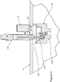
Figure 2 is a front, schematic view showing an enclosure means of an embodiment of the calibration system according to the present invention arranged in a first position; -
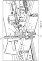
Figure 3 is a perspective, isometric view showing the enclosure means in the first position; -
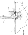
Figure 4 is a front, schematic view showing the enclosure means of the embodiment of the calibration system inFigures 2 and3 arranged in a second position; -
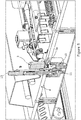
Figure 5 is a perspective, isometric view showing the enclosure means in the second position. - Referring firstly to
Figure 1 , there is shown in general terms an embodiment of a controlledatmosphere workstation 1 according to the present invention. The workstation comprises an internal working chamber (not shown) in which samples, products, devices can be held under specific atmospheric conditions and in which operations can be carried out. The workstation comprises at least one porthole, preferably a pair ofportholes Figure 1 , the atmosphere control means control the oxygen concentration to provide an anaerobic atmosphere in the working chamber. The workstation includes at least one gas sensor to monitor the chemical composition of the atmosphere. In the embodiment depicted inFigure 1 , the workstation comprises anoxygen sensor 3 with asensing head 3a to monitor the oxygen concentration of the atmosphere in the working chamber. The gas sensor is preferably mounted on the topside of the working chamber as shown inFigure 1 . Thesensing head 3a protrudes through an aperture in anupper wall 4 of the working chamber so that it is exposed to the atmosphere in the working chamber. The rear of the gas sensor is preferably protected by a lid of the workstation (not shown). In normal operation of the workstation, the oxygen sensor continuously monitors the concentration of oxygen present in the controlled atmosphere and compares the sensed concentration to an operator-selected value. Additional oxygen and/or other gases may be introduced on demand so as to maintain the controlled atmosphere with the operator-selected oxygen concentration. - To counteract sensor deterioration, the present invention provides a calibration system and method for automatically calibrating at least one gas sensor arranged in-situ in a controlled atmosphere workstation.
-
Figures 2 to 5 depict an embodiment of a calibration system that is configured to calibrate the oxygen sensor mounted in the controlled atmosphere workstation shown inFigure 1 . - The calibration system comprises microprocessor control means (not shown) to automate the calibration process and minimise, preferably exclude, operator involvement.
- In the embodiment depicted in
Figures 2 to 5 , the calibration system includes a button to activate calibration (not shown). The button may be incorporated as part of a display, for example thedisplay 5 of the workstation. The microprocessor is configured to initiate calibration of the oxygen sensor when an operator actuates the button. - To avoid any deterioration in performance, the microprocessor is configured to activate a warning after a certain time period has lapsed to warn the operator that the sensor requires calibration. The warning may be a warning message that appears on the
display 5 and is removed when the operator actuates the calibration activation button. - To inform the operator, the microprocessor may be further configured to activate a message on the
display 5 to indicate the status of the calibration process, when the calibration process is completed and when the workstation is ready for use again. - The microprocessor may additionally or alternatively be pre-programmed to automatically calibrate the oxygen sensor after a certain time period has lapsed, preferably in good time before the accuracy of the sensor degrades.
- To allow the sensor to remain in-situ during the calibration process and not compromise the controlled atmosphere in the working chamber, the calibration system comprises a
vessel 10 that is arrangeable to enclose thesensing head 3a. The vessel is movable between a first position and a second position as shown inFigures 2 to 5 . - In the first position, the
vessel 10 is spaced a certain distance d from thesensing head 3a in an "open position". As a result, thesensing head 3a is exposed and it is able to monitor the controlled atmosphere of the workstation under normal operating conditions. - In the second position, the
vessel 10 is arranged in engagement with theupper wall 4, enclosing thesensing head 3a of the oxygen sensor in acalibration chamber 11. When engaging the wall, the vessel is deemed to be in a "closed position". The sensor is isolated from the controlled atmosphere of the workstation and so monitors the oxygen content of the atmosphere in the calibration chamber. - In the embodiment depicted, the
vessel 10 is a cylinder like vessel with aninternal cavity space 10a, closed bottom 10b and open top 10c. Acircumferential seal 12 extends around the top edge of the cylinder to enhance the engagement with the upper wall surface. When the vessel and upper wall engage, the cavity of the cylinder and upper wall surface define thecalibration chamber 11. - The calibration system comprises a
mechanism 13 to move thevessel 10 between the first and second positions. In the embodiment depicted, the mechanism is a pneumatic piston operable by the microprocessor. The mechanism is spring loaded to bias the vessel in the first position. During calibration, the microprocessor is configured to control the pneumatic actuation of the piston so as to move the vessel from the first position to the second position and then allow thevessel 10 to return to the first position once the sensor has been calibrated. - The calibration system comprises a gas supply line to supply gas into the calibration chamber to calibrate the oxygen sensor. The operation of the gas supply line is controlled by the microprocessor.
- In the embodiment depicted, the gas supply line is configured to initially supply pressurised nitrogen with a 0% oxygen concentration to flush out the calibration chamber. Under the control of the microprocessor, the 0% oxygen concentration sensed by the sensor is calibrated as a minimum oxygen concentration for the sensing scale of the sensor.
- After calibrating the 0% oxygen concentration reference point, the gas supply line is further configured to supply pressured ambient air with a 20.9% oxygen content to flush out the calibration chamber. Under the control of the microprocessor, the 20.9% oxygen concentration sensed by the sensor is subsequently calibrated as a maximum oxygen concentration for the sensing scale of the sensor.
- After calibrating the sensor, the microprocessor actuates the mechanism to move the vessel back to the first position and the sensing of the oxygen concentration of the controlled atmosphere is reinstated.
- Although the invention has been described above with reference to one or more preferred embodiments, it will be appreciated that various changes or modifications may be made without departing from the scope of the invention as defined in the appended claims.
Claims (14)
- An automated calibration system for calibrating a gas sensor (3) in-situ within a controlled atmosphere workstation (1), the system comprising:microprocessor control means for automatically controlling the calibration system;a gas supply line, operable by the control means, and configured to sequentially supply at least one gas with a predetermined gas concentration into a calibration chamber (11) such that at least one gas concentration reference point can be determined to calibrate a sensing scale of the sensor (3);enclosure means (10) movable between a first position and a second position;a drive mechanism (13), operable by the control means, for moving the enclosure means (10) between the first position and the second position;wherein in the first position the enclosure means is arranged in a spaced relationship from the sensor such that a sensing head (3a) of the sensor (3) is exposed to the controlled atmosphere of the workstation; andin the second position the enclosure means is arranged in engagement with at least one surface of the controlled atmosphere workstation so as to define the calibration chamber (11) and enclose the sensing head (3a) in the calibration chamber.
- A system according to claim 1, wherein the enclosure means comprises a vessel (10) with a cavity (10a) in which the sensing head can be received and a cavity edge for engagement with a surface encircling the sensor;
and/or wherein the drive mechanism comprises a pneumatic piston and/or a motor driven shaft. - A system according to claim 1 or 2, wherein
the gas supply line is configured to flush a gas with a first gas concentration through the calibration chamber; and
the sensor is configured to monitor the first gas concentration under the control of the control means; and
the control means is configured to determine a first gas concentration point for the sensing scale of the sensor in accordance with the sensor response to the first gas concentration;
optionally wherein
the gas supply line is configured to flush a gas with a second gas concentration through the calibration chamber; and
the sensor is configured to monitor the second gas concentration under the control of the control means; and
the control means is configured to determine a second gas concentration point for the sensing scale of the sensor in accordance with the sensor response to the second gas concentration. - A system according to any preceding claim, wherein the gas sensor is an oxygen sensor (3).
- A system according to claim 4 when dependent on claim 3, wherein the gas with the first gas concentration is nitrogen with 0% oxygen concentration;
optionally wherein the gas with the second gas concentration is ambient air with 20.9% oxygen concentration. - A system according to any preceding claim, wherein the control means comprises an operator activation button to initiate the calibration of the sensor when actuated by the operator;
and/or wherein the control means comprises a time lapse activation to automatically initiate calibration of the sensor after a predetermined time period;
and/or wherein the control means comprises a time lapse activation to identify the sensor requires calibration after a predetermined time period and activate an operator warning. - A controlled atmosphere workstation comprising a gas sensor and calibration system for automatically calibrating the gas sensor in-situ according to any of claims 1 to 6.
- An automated method for calibrating a gas sensor in-situ within a controlled atmosphere workstation using the automated calibration system according to any one of claims 1 to 6 comprising:arranging an enclosure means in a second position so as to define a calibration chamber in which a sensing head of the gas sensor is enclosed;flushing a gas with a predetermined first gas concentration through the calibration chamber;monitoring the sensor response to the first gas concentration; andcalibrating a first gas concentration reference point on a sensing scale of the sensor in accordance with the sensor response to the first gas concentration.
- The method according to claim 8, wherein the arranging of the enclosure means comprises moving the enclosure means from a first position to a second position using a mechanism under the control of automatic control means; wherein in the first position, the enclosure means is spaced from the sensing head and the sensing head is exposed to the controlled atmosphere of the workstation; and wherein in the second position, the enclosure means engages at least one further surface to define the calibration chamber and enclose the sensing head within the calibration chamber.
- The method according to claim 8 or 9, wherein the flushing of the gas with the first gas concentration comprises using a gas supply line under the control of automatic microprocessor control means to supply the gas under pressure to the calibration chamber.
- The method according to any of claims 8 to 10, wherein the monitoring and calibrating is controlled by automatic control means.
- The method according to any of claims 8 to 11, further comprising:flushing a gas with a second gas concentration through the calibration chamber;monitoring the sensor response to the second gas concentration; andcalibrating a second gas concentration reference point on the sensor scale in accordance with the sensor response to the second gas concentration;optionally wherein the flushing of the gas with a second gas concentration may comprise using a gas supply line controlled by automatic control means to supply the second gas under pressure to the calibration chamber;further optionally wherein the monitoring and calibrating is controlled by automatic control means.
- The method according to any of claims 8 to 12, further comprising:
initiating calibration when an operator activation button is actuated. - The method according to any of claims 8 to 13, further comprising:moving of the enclosure means from the second position to the first position using the mechanism under the control of the automatic control means when the sensor has been calibrated; andreinstating the sensing of a gas in the controlled atmosphere of the workstation.
Applications Claiming Priority (1)
| Application Number | Priority Date | Filing Date | Title |
|---|---|---|---|
| GB1511140.4A GB2539690B (en) | 2015-06-24 | 2015-06-24 | Sensor calibration system and method for a controlled atmosphere workstation |
Publications (2)
| Publication Number | Publication Date |
|---|---|
| EP3109635A1 EP3109635A1 (en) | 2016-12-28 |
| EP3109635B1 true EP3109635B1 (en) | 2019-08-28 |
Family
ID=53784463
Family Applications (1)
| Application Number | Title | Priority Date | Filing Date |
|---|---|---|---|
| EP16175511.1A Active EP3109635B1 (en) | 2015-06-24 | 2016-06-21 | Sensor calibration system and method for a controlled atmosphere workstation |
Country Status (3)
| Country | Link |
|---|---|
| US (1) | US10451596B2 (en) |
| EP (1) | EP3109635B1 (en) |
| GB (1) | GB2539690B (en) |
Families Citing this family (4)
| Publication number | Priority date | Publication date | Assignee | Title |
|---|---|---|---|---|
| GB201205766D0 (en) * | 2012-03-30 | 2012-05-16 | Oxford Optronix Ltd | Controlled atmosphere workstation |
| GB2552991B (en) * | 2016-08-18 | 2022-02-02 | Whitley Don Scient Ltd | Gas sensor calibration system and method for a controlled atmosphere workstation |
| US20200363383A1 (en) * | 2017-08-25 | 2020-11-19 | Kam Fu Chow | System and method for calibrating a gas detecting device |
| SG11202012779PA (en) | 2019-05-17 | 2021-12-30 | Carrier Corp | Gas detector test and calibration method and apparatus |
Citations (1)
| Publication number | Priority date | Publication date | Assignee | Title |
|---|---|---|---|---|
| US4489590A (en) * | 1982-01-25 | 1984-12-25 | Delphian Corporation | Method and apparatus for gas detector calibration |
Family Cites Families (9)
| Publication number | Priority date | Publication date | Assignee | Title |
|---|---|---|---|---|
| US3495437A (en) * | 1968-05-09 | 1970-02-17 | United States Steel Corp | Method and apparatus for zero-setting and calibrating vapor-responsive detectors |
| US4279142A (en) * | 1975-09-25 | 1981-07-21 | Westinghouse Electric Corp. | Technique for in situ calibration of a gas detector |
| US4039933A (en) * | 1976-03-25 | 1977-08-02 | Instrumentation Laboratory, Inc. | Continuous calibration system and method for analytical instruments |
| US4578986A (en) * | 1984-07-06 | 1986-04-01 | Champion International Corporation | Gas analyzer for dry/dusty kilns |
| US4742708A (en) * | 1986-08-13 | 1988-05-10 | Beckman Industrial Corporation | Apparatus for electrochemical sensor calibration |
| DE19708052C2 (en) * | 1996-04-13 | 1998-04-16 | Ust Umweltsensortechnik Gmbh | Device for automatic calibration of gas sensors |
| GB201205766D0 (en) * | 2012-03-30 | 2012-05-16 | Oxford Optronix Ltd | Controlled atmosphere workstation |
| CN104374879B (en) * | 2014-11-19 | 2017-01-18 | 威格气体纯化科技(苏州)股份有限公司 | Oxygen sensor calibration method and on-line calibration device |
| CN104655567B (en) * | 2015-03-19 | 2017-11-10 | 重庆川仪分析仪器有限公司 | The ultraviolet gas analyzing apparatus that can be calibrated automatically |
-
2015
- 2015-06-24 GB GB1511140.4A patent/GB2539690B/en active Active
-
2016
- 2016-06-21 EP EP16175511.1A patent/EP3109635B1/en active Active
- 2016-06-22 US US15/189,653 patent/US10451596B2/en active Active
Patent Citations (1)
| Publication number | Priority date | Publication date | Assignee | Title |
|---|---|---|---|---|
| US4489590A (en) * | 1982-01-25 | 1984-12-25 | Delphian Corporation | Method and apparatus for gas detector calibration |
Also Published As
| Publication number | Publication date |
|---|---|
| US10451596B2 (en) | 2019-10-22 |
| GB2539690B (en) | 2019-03-27 |
| US20160377584A1 (en) | 2016-12-29 |
| GB201511140D0 (en) | 2015-08-05 |
| EP3109635A1 (en) | 2016-12-28 |
| GB2539690A (en) | 2016-12-28 |
Similar Documents
| Publication | Publication Date | Title |
|---|---|---|
| US10451596B2 (en) | Sensor calibration systems and method for a controlled atmosphere workstation | |
| TWI533391B (en) | Method and device for transporting processed objects and computer readable storage medium for storing programs | |
| KR20130135367A (en) | Industrial robot and method for controlling an industrial robot | |
| US10307820B2 (en) | Suction pressure casting method | |
| EP3470811B1 (en) | Device and method for testing integrity of glove and glove port of an isolator | |
| CN111801191B (en) | Method and system for forming vacuum insulated containers | |
| AU2021209192A1 (en) | A Processing Machine for an Additive Manufacturing Build Assembly | |
| JP2008134246A (en) | Workspace specimen detection system and method using fan for moving sample from workspace to sensor | |
| KR20170131639A (en) | Upper dome temperature closed loop control | |
| GB2569901A (en) | Sensor calibration system and method for a controlled atmosphere workstation | |
| US4570051A (en) | Enclosing a gas in a nuclear reactor fuel rod | |
| JP2017002353A (en) | Substrate treatment apparatus, and production method of semiconductor device | |
| JP2829367B2 (en) | Wafer transfer method | |
| US20160322596A1 (en) | A packaging device and method for manufacturing the oled display screen | |
| JPWO2006104121A1 (en) | Semiconductor manufacturing equipment | |
| GB2552991A (en) | Gas sensor calibration system and method for a controlled atmosphere workstation | |
| EP1388284B1 (en) | Structure for environmentally-safe disinfestation using mobile chambers | |
| JP2007212338A (en) | Sealing inspection device and sealing inspection method | |
| JPH0130108B2 (en) | ||
| JP3772640B2 (en) | Centrifuge | |
| JP5303070B1 (en) | Avocado ripening method | |
| KR101868669B1 (en) | Control apparatus, substrate processing apparatus, and substrate processing system | |
| JP5142353B2 (en) | Substrate processing apparatus, substrate processing apparatus abnormality detection method, substrate processing system, substrate processing apparatus abnormality detection program, and semiconductor device manufacturing method | |
| JP2013055239A (en) | Substrate processing apparatus | |
| JP6914639B2 (en) | Monitoring system |
Legal Events
| Date | Code | Title | Description |
|---|---|---|---|
| PUAI | Public reference made under article 153(3) epc to a published international application that has entered the european phase |
Free format text: ORIGINAL CODE: 0009012 |
|
| STAA | Information on the status of an ep patent application or granted ep patent |
Free format text: STATUS: THE APPLICATION HAS BEEN PUBLISHED |
|
| AK | Designated contracting states |
Kind code of ref document: A1 Designated state(s): AL AT BE BG CH CY CZ DE DK EE ES FI FR GB GR HR HU IE IS IT LI LT LU LV MC MK MT NL NO PL PT RO RS SE SI SK SM TR |
|
| AX | Request for extension of the european patent |
Extension state: BA ME |
|
| STAA | Information on the status of an ep patent application or granted ep patent |
Free format text: STATUS: REQUEST FOR EXAMINATION WAS MADE |
|
| 17P | Request for examination filed |
Effective date: 20170628 |
|
| RBV | Designated contracting states (corrected) |
Designated state(s): AL AT BE BG CH CY CZ DE DK EE ES FI FR GB GR HR HU IE IS IT LI LT LU LV MC MK MT NL NO PL PT RO RS SE SI SK SM TR |
|
| STAA | Information on the status of an ep patent application or granted ep patent |
Free format text: STATUS: EXAMINATION IS IN PROGRESS |
|
| 17Q | First examination report despatched |
Effective date: 20180614 |
|
| GRAP | Despatch of communication of intention to grant a patent |
Free format text: ORIGINAL CODE: EPIDOSNIGR1 |
|
| STAA | Information on the status of an ep patent application or granted ep patent |
Free format text: STATUS: GRANT OF PATENT IS INTENDED |
|
| INTG | Intention to grant announced |
Effective date: 20181122 |
|
| GRAJ | Information related to disapproval of communication of intention to grant by the applicant or resumption of examination proceedings by the epo deleted |
Free format text: ORIGINAL CODE: EPIDOSDIGR1 |
|
| STAA | Information on the status of an ep patent application or granted ep patent |
Free format text: STATUS: EXAMINATION IS IN PROGRESS |
|
| INTC | Intention to grant announced (deleted) | ||
| GRAP | Despatch of communication of intention to grant a patent |
Free format text: ORIGINAL CODE: EPIDOSNIGR1 |
|
| STAA | Information on the status of an ep patent application or granted ep patent |
Free format text: STATUS: GRANT OF PATENT IS INTENDED |
|
| RIN1 | Information on inventor provided before grant (corrected) |
Inventor name: KITSELL, EVAN Inventor name: BOAST, DAVID |
|
| INTG | Intention to grant announced |
Effective date: 20190513 |
|
| RAP1 | Party data changed (applicant data changed or rights of an application transferred) |
Owner name: DON WHITLEY SCIENTIFIC LIMITED |
|
| GRAS | Grant fee paid |
Free format text: ORIGINAL CODE: EPIDOSNIGR3 |
|
| GRAA | (expected) grant |
Free format text: ORIGINAL CODE: 0009210 |
|
| STAA | Information on the status of an ep patent application or granted ep patent |
Free format text: STATUS: THE PATENT HAS BEEN GRANTED |
|
| AK | Designated contracting states |
Kind code of ref document: B1 Designated state(s): AL AT BE BG CH CY CZ DE DK EE ES FI FR GB GR HR HU IE IS IT LI LT LU LV MC MK MT NL NO PL PT RO RS SE SI SK SM TR |
|
| REG | Reference to a national code |
Ref country code: GB Ref legal event code: FG4D |
|
| REG | Reference to a national code |
Ref country code: CH Ref legal event code: EP |
|
| REG | Reference to a national code |
Ref country code: AT Ref legal event code: REF Ref document number: 1173032 Country of ref document: AT Kind code of ref document: T Effective date: 20190915 |
|
| REG | Reference to a national code |
Ref country code: IE Ref legal event code: FG4D |
|
| REG | Reference to a national code |
Ref country code: DE Ref legal event code: R096 Ref document number: 602016019277 Country of ref document: DE |
|
| REG | Reference to a national code |
Ref country code: NL Ref legal event code: MP Effective date: 20190828 |
|
| REG | Reference to a national code |
Ref country code: LT Ref legal event code: MG4D |
|
| PG25 | Lapsed in a contracting state [announced via postgrant information from national office to epo] |
Ref country code: NL Free format text: LAPSE BECAUSE OF FAILURE TO SUBMIT A TRANSLATION OF THE DESCRIPTION OR TO PAY THE FEE WITHIN THE PRESCRIBED TIME-LIMIT Effective date: 20190828 Ref country code: LT Free format text: LAPSE BECAUSE OF FAILURE TO SUBMIT A TRANSLATION OF THE DESCRIPTION OR TO PAY THE FEE WITHIN THE PRESCRIBED TIME-LIMIT Effective date: 20190828 Ref country code: SE Free format text: LAPSE BECAUSE OF FAILURE TO SUBMIT A TRANSLATION OF THE DESCRIPTION OR TO PAY THE FEE WITHIN THE PRESCRIBED TIME-LIMIT Effective date: 20190828 Ref country code: BG Free format text: LAPSE BECAUSE OF FAILURE TO SUBMIT A TRANSLATION OF THE DESCRIPTION OR TO PAY THE FEE WITHIN THE PRESCRIBED TIME-LIMIT Effective date: 20191128 Ref country code: HR Free format text: LAPSE BECAUSE OF FAILURE TO SUBMIT A TRANSLATION OF THE DESCRIPTION OR TO PAY THE FEE WITHIN THE PRESCRIBED TIME-LIMIT Effective date: 20190828 Ref country code: FI Free format text: LAPSE BECAUSE OF FAILURE TO SUBMIT A TRANSLATION OF THE DESCRIPTION OR TO PAY THE FEE WITHIN THE PRESCRIBED TIME-LIMIT Effective date: 20190828 Ref country code: NO Free format text: LAPSE BECAUSE OF FAILURE TO SUBMIT A TRANSLATION OF THE DESCRIPTION OR TO PAY THE FEE WITHIN THE PRESCRIBED TIME-LIMIT Effective date: 20191128 Ref country code: PT Free format text: LAPSE BECAUSE OF FAILURE TO SUBMIT A TRANSLATION OF THE DESCRIPTION OR TO PAY THE FEE WITHIN THE PRESCRIBED TIME-LIMIT Effective date: 20191230 |
|
| PG25 | Lapsed in a contracting state [announced via postgrant information from national office to epo] |
Ref country code: LV Free format text: LAPSE BECAUSE OF FAILURE TO SUBMIT A TRANSLATION OF THE DESCRIPTION OR TO PAY THE FEE WITHIN THE PRESCRIBED TIME-LIMIT Effective date: 20190828 Ref country code: IS Free format text: LAPSE BECAUSE OF FAILURE TO SUBMIT A TRANSLATION OF THE DESCRIPTION OR TO PAY THE FEE WITHIN THE PRESCRIBED TIME-LIMIT Effective date: 20191228 Ref country code: ES Free format text: LAPSE BECAUSE OF FAILURE TO SUBMIT A TRANSLATION OF THE DESCRIPTION OR TO PAY THE FEE WITHIN THE PRESCRIBED TIME-LIMIT Effective date: 20190828 Ref country code: AL Free format text: LAPSE BECAUSE OF FAILURE TO SUBMIT A TRANSLATION OF THE DESCRIPTION OR TO PAY THE FEE WITHIN THE PRESCRIBED TIME-LIMIT Effective date: 20190828 Ref country code: RS Free format text: LAPSE BECAUSE OF FAILURE TO SUBMIT A TRANSLATION OF THE DESCRIPTION OR TO PAY THE FEE WITHIN THE PRESCRIBED TIME-LIMIT Effective date: 20190828 Ref country code: GR Free format text: LAPSE BECAUSE OF FAILURE TO SUBMIT A TRANSLATION OF THE DESCRIPTION OR TO PAY THE FEE WITHIN THE PRESCRIBED TIME-LIMIT Effective date: 20191129 |
|
| REG | Reference to a national code |
Ref country code: AT Ref legal event code: MK05 Ref document number: 1173032 Country of ref document: AT Kind code of ref document: T Effective date: 20190828 |
|
| PG25 | Lapsed in a contracting state [announced via postgrant information from national office to epo] |
Ref country code: TR Free format text: LAPSE BECAUSE OF FAILURE TO SUBMIT A TRANSLATION OF THE DESCRIPTION OR TO PAY THE FEE WITHIN THE PRESCRIBED TIME-LIMIT Effective date: 20190828 |
|
| PG25 | Lapsed in a contracting state [announced via postgrant information from national office to epo] |
Ref country code: AT Free format text: LAPSE BECAUSE OF FAILURE TO SUBMIT A TRANSLATION OF THE DESCRIPTION OR TO PAY THE FEE WITHIN THE PRESCRIBED TIME-LIMIT Effective date: 20190828 Ref country code: DK Free format text: LAPSE BECAUSE OF FAILURE TO SUBMIT A TRANSLATION OF THE DESCRIPTION OR TO PAY THE FEE WITHIN THE PRESCRIBED TIME-LIMIT Effective date: 20190828 Ref country code: EE Free format text: LAPSE BECAUSE OF FAILURE TO SUBMIT A TRANSLATION OF THE DESCRIPTION OR TO PAY THE FEE WITHIN THE PRESCRIBED TIME-LIMIT Effective date: 20190828 Ref country code: RO Free format text: LAPSE BECAUSE OF FAILURE TO SUBMIT A TRANSLATION OF THE DESCRIPTION OR TO PAY THE FEE WITHIN THE PRESCRIBED TIME-LIMIT Effective date: 20190828 Ref country code: IT Free format text: LAPSE BECAUSE OF FAILURE TO SUBMIT A TRANSLATION OF THE DESCRIPTION OR TO PAY THE FEE WITHIN THE PRESCRIBED TIME-LIMIT Effective date: 20190828 Ref country code: PL Free format text: LAPSE BECAUSE OF FAILURE TO SUBMIT A TRANSLATION OF THE DESCRIPTION OR TO PAY THE FEE WITHIN THE PRESCRIBED TIME-LIMIT Effective date: 20190828 |
|
| PG25 | Lapsed in a contracting state [announced via postgrant information from national office to epo] |
Ref country code: SM Free format text: LAPSE BECAUSE OF FAILURE TO SUBMIT A TRANSLATION OF THE DESCRIPTION OR TO PAY THE FEE WITHIN THE PRESCRIBED TIME-LIMIT Effective date: 20190828 Ref country code: IS Free format text: LAPSE BECAUSE OF FAILURE TO SUBMIT A TRANSLATION OF THE DESCRIPTION OR TO PAY THE FEE WITHIN THE PRESCRIBED TIME-LIMIT Effective date: 20200224 Ref country code: CZ Free format text: LAPSE BECAUSE OF FAILURE TO SUBMIT A TRANSLATION OF THE DESCRIPTION OR TO PAY THE FEE WITHIN THE PRESCRIBED TIME-LIMIT Effective date: 20190828 Ref country code: SK Free format text: LAPSE BECAUSE OF FAILURE TO SUBMIT A TRANSLATION OF THE DESCRIPTION OR TO PAY THE FEE WITHIN THE PRESCRIBED TIME-LIMIT Effective date: 20190828 |
|
| REG | Reference to a national code |
Ref country code: DE Ref legal event code: R097 Ref document number: 602016019277 Country of ref document: DE |
|
| PLBE | No opposition filed within time limit |
Free format text: ORIGINAL CODE: 0009261 |
|
| STAA | Information on the status of an ep patent application or granted ep patent |
Free format text: STATUS: NO OPPOSITION FILED WITHIN TIME LIMIT |
|
| PG2D | Information on lapse in contracting state deleted |
Ref country code: IS |
|
| 26N | No opposition filed |
Effective date: 20200603 |
|
| PG25 | Lapsed in a contracting state [announced via postgrant information from national office to epo] |
Ref country code: SI Free format text: LAPSE BECAUSE OF FAILURE TO SUBMIT A TRANSLATION OF THE DESCRIPTION OR TO PAY THE FEE WITHIN THE PRESCRIBED TIME-LIMIT Effective date: 20190828 |
|
| REG | Reference to a national code |
Ref country code: DE Ref legal event code: R082 Ref document number: 602016019277 Country of ref document: DE Representative=s name: HL KEMPNER PATENTANWAELTE, SOLICITORS (ENGLAND, DE Ref country code: DE Ref legal event code: R082 Ref document number: 602016019277 Country of ref document: DE Representative=s name: HL KEMPNER PATENTANWALT, RECHTSANWALT, SOLICIT, DE Ref country code: DE Ref legal event code: R082 Ref document number: 602016019277 Country of ref document: DE Representative=s name: HL KEMPNER PARTG MBB, DE |
|
| PG25 | Lapsed in a contracting state [announced via postgrant information from national office to epo] |
Ref country code: MC Free format text: LAPSE BECAUSE OF FAILURE TO SUBMIT A TRANSLATION OF THE DESCRIPTION OR TO PAY THE FEE WITHIN THE PRESCRIBED TIME-LIMIT Effective date: 20190828 |
|
| REG | Reference to a national code |
Ref country code: CH Ref legal event code: PL |
|
| PG25 | Lapsed in a contracting state [announced via postgrant information from national office to epo] |
Ref country code: LU Free format text: LAPSE BECAUSE OF NON-PAYMENT OF DUE FEES Effective date: 20200621 |
|
| REG | Reference to a national code |
Ref country code: BE Ref legal event code: MM Effective date: 20200630 |
|
| PG25 | Lapsed in a contracting state [announced via postgrant information from national office to epo] |
Ref country code: IE Free format text: LAPSE BECAUSE OF NON-PAYMENT OF DUE FEES Effective date: 20200621 Ref country code: CH Free format text: LAPSE BECAUSE OF NON-PAYMENT OF DUE FEES Effective date: 20200630 Ref country code: LI Free format text: LAPSE BECAUSE OF NON-PAYMENT OF DUE FEES Effective date: 20200630 |
|
| PG25 | Lapsed in a contracting state [announced via postgrant information from national office to epo] |
Ref country code: BE Free format text: LAPSE BECAUSE OF NON-PAYMENT OF DUE FEES Effective date: 20200630 |
|
| PGFP | Annual fee paid to national office [announced via postgrant information from national office to epo] |
Ref country code: FR Payment date: 20210630 Year of fee payment: 6 |
|
| PG25 | Lapsed in a contracting state [announced via postgrant information from national office to epo] |
Ref country code: MT Free format text: LAPSE BECAUSE OF FAILURE TO SUBMIT A TRANSLATION OF THE DESCRIPTION OR TO PAY THE FEE WITHIN THE PRESCRIBED TIME-LIMIT Effective date: 20190828 Ref country code: CY Free format text: LAPSE BECAUSE OF FAILURE TO SUBMIT A TRANSLATION OF THE DESCRIPTION OR TO PAY THE FEE WITHIN THE PRESCRIBED TIME-LIMIT Effective date: 20190828 |
|
| PG25 | Lapsed in a contracting state [announced via postgrant information from national office to epo] |
Ref country code: MK Free format text: LAPSE BECAUSE OF FAILURE TO SUBMIT A TRANSLATION OF THE DESCRIPTION OR TO PAY THE FEE WITHIN THE PRESCRIBED TIME-LIMIT Effective date: 20190828 |
|
| PG25 | Lapsed in a contracting state [announced via postgrant information from national office to epo] |
Ref country code: FR Free format text: LAPSE BECAUSE OF NON-PAYMENT OF DUE FEES Effective date: 20220630 |
|
| P01 | Opt-out of the competence of the unified patent court (upc) registered |
Effective date: 20230526 |
|
| PGFP | Annual fee paid to national office [announced via postgrant information from national office to epo] |
Ref country code: GB Payment date: 20250602 Year of fee payment: 10 |
|
| PGFP | Annual fee paid to national office [announced via postgrant information from national office to epo] |
Ref country code: DE Payment date: 20250630 Year of fee payment: 10 |