JP3772640B2 - Centrifuge - Google Patents
Centrifuge Download PDFInfo
- Publication number
- JP3772640B2 JP3772640B2 JP2000147668A JP2000147668A JP3772640B2 JP 3772640 B2 JP3772640 B2 JP 3772640B2 JP 2000147668 A JP2000147668 A JP 2000147668A JP 2000147668 A JP2000147668 A JP 2000147668A JP 3772640 B2 JP3772640 B2 JP 3772640B2
- Authority
- JP
- Japan
- Prior art keywords
- rotor
- inert gas
- centrifuge
- rotor chamber
- chamber
- Prior art date
- Legal status (The legal status is an assumption and is not a legal conclusion. Google has not performed a legal analysis and makes no representation as to the accuracy of the status listed.)
- Expired - Fee Related
Links
Images
Classifications
-
- B—PERFORMING OPERATIONS; TRANSPORTING
- B04—CENTRIFUGAL APPARATUS OR MACHINES FOR CARRYING-OUT PHYSICAL OR CHEMICAL PROCESSES
- B04B—CENTRIFUGES
- B04B7/00—Elements of centrifuges
- B04B7/02—Casings; Lids
- B04B7/06—Safety devices ; Regulating
-
- B—PERFORMING OPERATIONS; TRANSPORTING
- B04—CENTRIFUGAL APPARATUS OR MACHINES FOR CARRYING-OUT PHYSICAL OR CHEMICAL PROCESSES
- B04B—CENTRIFUGES
- B04B13/00—Control arrangements specially designed for centrifuges; Program control of centrifuges
-
- B—PERFORMING OPERATIONS; TRANSPORTING
- B04—CENTRIFUGAL APPARATUS OR MACHINES FOR CARRYING-OUT PHYSICAL OR CHEMICAL PROCESSES
- B04B—CENTRIFUGES
- B04B15/00—Other accessories for centrifuges
- B04B15/08—Other accessories for centrifuges for ventilating or producing a vacuum in the centrifuge
Landscapes
- Centrifugal Separators (AREA)
Description
【0001】
【発明の属する技術分野】
本発明は、引火性を有する試料を取り扱う遠心機の安全性に関するものである。
【0002】
【従来の技術】
従来から試料の分離作業等には、駆動装置によって高速回転され且つ試料を収容可能なロータを具備して成る遠心機が使用されている。収容される試料は種々あるが作業内容によっては引火性を有する有機溶媒を取り扱う場合がある。この場合、作業者は引火しないよう細心の注意をはらいながら作業を行っているが、何らかの原因によって試料に引火し爆発してしまう危険性はゼロとは言えなかった。例えば回転するロータのカバが離脱して試料の入ったチューブから引火性の試料が漏れ出た状態で、更に金属性の上記カバとロータとの高速衝突時に火花が発生すると、この火花が試料に引火してしまう場合などが上げられる。そこでロータを真空中または減圧状態中にて回転させることにより空気量(酸素量)を下げ引火しにくくすることが考えられるが、この場合には上述したようロータを真空状態で回転させるため、遠心機のロータ室内やロータ自体を耐真空構成にする必要があると共に、取り扱い及び遠心機構成が複雑化してしまうという問題が生じる。なお、真空引きするそもそもの目的は、回転するロータの風損低減にある。
【0003】
また、実開平03−59053号には、ロータを不活性ガス雰囲気下で回転させる装置が開示されており、これにより引火の危険性を抑えている。しかし、不活性ガスをロータ室に封入しても何らかの要因でロータ回転時に外部から空気が侵入してしまい酸素の濃度が上昇してしまうと引火の可能性が出てくる。更に不活性ガスの充填度合いを作業者の目や耳でチェックしているため、仮に不活性ガスの充填度合いが少なくなっているにも係らず人的ミスにより見落してしまった場合などには引火の危険性が生じてしまう。
【0004】
【発明が解決しようとする課題】
上述した通り、引火性を有する有機溶媒を取り扱う場合には、ロータを不活性ガス雰囲気下で回転させており、更に不活性ガスの充填度合いを視覚或いは聴覚によりチェックしているため、仮に不活性ガスの充填度合いが少なくなっているにも係らず見落してしまうと引火の危険性が生じてしまうという問題があった。
【0005】
本発明の目的は、上記問題を解消し、ロータ室内の雰囲気が不活性ガスに置換されていることを確認し、この置換状態が定められた初期条件より低下した場合には、引火の恐れがあるため自動停止させることで、引火を未然に防ぐ安全性に優れた遠心機を提供することである。
【0006】
【課題を解決するための手段】
上記目的は、試料の入ったロータを回転させるロータ室内を不活性ガスで充満させ引火しないようにすることと、常にロータ室内が一定の不活性ガスで充満されていることを監視し、万一一定値を超え引火の可能性が生じた場合には遠心機の運転を停止させることにより達成される。
【0007】
駆動装置と、駆動装置によって回転され且つ引火性を有する有機溶媒を収容可能なロータと、ロータを収納するロータ室と、ロータ室内に不活性ガスを充満させるための供給手段とを備えた遠心機において、ロータ室内の酸素濃度を測定し、更に測定値が予め定められた一定値をオバーした場合に駆動装置を停止させるための制御部を設けることにより達成される。
【0008】
駆動装置と、駆動装置によって回転され且つ引火性を有する有機溶媒を収容可能なロータと、ロータを収納するロータ室と、ロータ室内に不活性ガスを充満させるための供給手段とを備えた遠心機において、ロータ室内の不活性ガス濃度を測定し、更に測定値が予め定められた一定値を下回る場合に駆動装置を停止させるための制御部を設けることにより達成される。
【0009】
駆動装置と、駆動装置によって回転され且つ引火性を有する有機溶媒を収容可能なロータと、ロータを収納するロータ室と、ロータ室内に不活性ガスを充満させるための供給手段とを備えた遠心機において、ロータ室内に漏れ出た試料濃度を測定し、更に測定値が予め定められた一定値をオバーした場合に駆動装置を停止させるための制御部を設けることにより達成される。
【0010】
【発明の実施の形態】
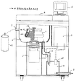
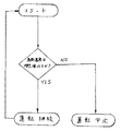
本実施例を図1及び図2を用いて説明する。図1は本実施例における遠心機を示す一部縦断側面図、図2は本遠心機における気体濃度検出後の処理方法を示すフローチャートである。遠心機本体は遠心分離する試料を保持し且つ高速回転するロータ1を回転駆動させる駆動装置である駆動モータ2、該ロータ1を収納するロータ室3、該ロータ室を閉塞可能なドア4、駆動モータ2等の遠心機本体を制御する制御部5、本体の操作・入力を行う操作部6、ロータ室3内に不活性ガスを入れる供給口7、不活性ガスを排出する排出口8、不活性ガスを供給するガスボンベ9、ロータ室3内の酸素濃度を測定する酸素濃度計10、酸素濃度を安定して測定するためのバッファタンク11、ロータ室3とバッファタンク11を接続連通する連通路12から構成されている。このような構成を有する遠心機の操作手順としては、まず作業者がガスボンベ9のバルブを開き回転室3内に不活性ガスを流す。回転室3内或いはバッファタンク11内の酸素濃度或いは不活性ガス濃度を濃度計で測定し、問題のない濃度であると判断すれば起動スイッチを操作することで遠心機の駆動モータ2を起動して分離作業を開始することができる。無論、濃度的に問題がある場合には、作業者が起動スイッチを押しても駆動モータ2は起動しないよう制御されている。また、所定の濃度に達する前に作業者が起動スイッチを一度押していれば、問題のない濃度に達した時、自動的に駆動モータ2を起動させるよう制御しても良い。また、別の方法として、濃度測定を行っているあいだ駆動モータ2を問題のない一定回転数で整定させておき、濃度上問題がなければそこから加速制御させる方法でも良い。なお、ガスボンベ9のバルブ開閉は作業者が手動操作しているが、必要に応じて自動開閉されるよう制御しても良い。
【0011】
試料はロータ1内に装填し高速回転による遠心力によって分離される。通常試料を出し入れするためロータ1は試料を保持するロータボディ13部と高速回転時の風損低減と試料の外部への漏れ防止のためロータカバ14より構成されているのが一般的である。時としてロータカバ14の取りつけが不充分のため高速回転時にローターカバ14がロータボディ13より離脱してしまうことがある。この場合、ロータカバ14がロータ室3内を離脱移動する際に試料の入ったチューブを破損させ、当該試料がロータ室3内に飛散し且つロータカバ14とロータボディ13等の接触により発生する火花により、引火性のある試料であれば引火爆発の恐れがある。よって、引火防止策として、ロータ室3内に窒素ガス、アルゴンガス、ヘリウムガスなどの不活性ガスを収容するガスボンベ9から供給口7を介してロータ室3に不活性ガスを充満させた状態で、ロータ1を回転させる方法がある。なお、ロータ室3内の機密性が良ければ一度不活性ガスを充満させるだけで良いのだが、不活性ガスが経時的にロータ室3内から漏れ出てしまうことがあるため、できればロータ室3内に不活性ガスを連続的に流した方が効果的である。ロータ室3に入った不活性ガスは、バッファタンク11に連通している排出口8より遠心機本体外に排出されるが、ロータ室3内が不活性ガスに置換されている確証がないため、本実施例では安全性を高めるため、つまりロータ室3内に不活性ガスが問題なく充満されていることを確証するため、ロータ室3と排出口8との間に連通路12を介してバッファタンク11を設けている。そして該バッファタンク11内の酸素濃度を酸素濃度計10で測定し、この測定値が予め定められた一定値をオバーした場合には、制御部5によって駆動モータ2を停止させるよう制御する。言いかえれば不活性ガスに置換されているか否かを判断し、定められた一定の酸素濃度に置換されていない限り遠心機本体の運転を続行するよう制御されている。なお、不活性ガスへの置換状態の確証を酸素濃度測定で得ることとしたのは、試料への引火の度合いが雰囲気の酸素濃度によって大きな影響を受けていることと、不活性ガス濃度を測定するよりも酸素濃度を測定することの方が容易であることからである。無論不活性ガス濃度を直接測定し、この測定値が予め定められた一定値以下の場合に制御部5によって駆動モータ2を停止させるよう制御しても良く、またロータ1から漏れ出た引火性試料の濃度を測定し、この測定値が予め定められた一定値をオバーした場合に制御部5によって駆動モータ2を停止させるよう制御しても良い。
【0012】
また、本実施例では濃度計10を回転室3内ではなくバッファタンク11内に設けているが、この方がより安定した濃度測定を行えるからである。回転室3内であると空気がロータ1の回転によって掻き乱されるため圧力が安定せず測定に難があると共に、回転室3は冷却装置によって冷却されることから水分が存在するため濃度計10に何らかの影響を与えてしまうという不具合が生じるが、バッファタンク11内の上方に濃度計10を設けると水分は下方に溜まるので問題なく安定した濃度測定を行える。更に回転室3内に濃度計10を設ける場合には濃度計10の配置箇所及び組立構成上難しい面があるが、バッファタンク11内に濃度計10を設ける場合には圧力差に関係なく組立構成上容易に設けることができる。つまり、上述したように回転室3内や細い配管内等の気体濃度を測定するよりもバッファタンク11内の安定した気体濃度を測定した方がより安定した環境が作れ、正確に測定することが可能なためである。なお、排出口8から排出される不活性ガスは、屋外に排出されているが、場合によってはバイオハザード対策としてフィルタ等を介して回収しても良い。
【0013】
以上のことから、ロータ室3内の雰囲気が不活性ガスに置換されていることを確認し、この置換状態が定められた初期条件より低下した場合には、引火の恐れがあるため遠心機を自動停止させるよう制御することで、未然に引火事故を防げる安全性に優れた遠心機を提供することができる。
【0014】
【発明の効果】
本発明によれば、ロータ室内の雰囲気が不活性ガスで充満されていることを確認することで、試料への引火を防げる安全性に優れた遠心機を提供することができる。
【図面の簡単な説明】
【図1】 本発明になる遠心機を示す一部縦断側面図である。
【図2】 本発明になる遠心機の気体濃度検出後における処理方法を示すフローチャートである。
【符号の説明】
1はロータ、2は駆動モータ、3はロータ室、4はドア、5は制御部、6は操作部、7は供給口、8は排出口、9はガスボンベ、10は酸素濃度計、11はバッファタンク、12は連通路、13はロータボディ、14はロータカバ、15は試料の入ったチューブである。[0001]
BACKGROUND OF THE INVENTION
The present invention relates to the safety of a centrifuge that handles flammable samples.
[0002]
[Prior art]
Conventionally, a centrifuge having a rotor that can be rotated at a high speed by a driving device and can store a sample is used for sample separation work or the like. There are various types of samples to be accommodated, but depending on the work content, there are cases in which flammable organic solvents are handled. In this case, the operator is working while paying careful attention not to ignite, but the risk of the sample igniting and exploding for some reason was not zero. For example, if a spark occurs when the rotating rotor cover is detached and a flammable sample leaks out of the tube containing the sample, and the metallic cover and the rotor collide at high speed, this spark is applied to the sample. The case where it ignites is raised. Therefore, it is conceivable to reduce the air amount (oxygen amount) by rotating the rotor in a vacuum or in a reduced pressure state to make it difficult to ignite, but in this case, the rotor is rotated in a vacuum state as described above. There is a problem that the rotor chamber of the machine and the rotor itself need to have a vacuum resistant configuration, and the handling and the configuration of the centrifuge are complicated. The original purpose of evacuation is to reduce the windage loss of the rotating rotor.
[0003]
Japanese Utility Model Laid-Open No. 03-59053 discloses a device for rotating a rotor in an inert gas atmosphere, thereby suppressing the risk of ignition. However, even if the inert gas is sealed in the rotor chamber, there is a possibility of ignition if the oxygen concentration increases due to air entering from the outside during the rotor rotation due to some factor. In addition, since the inert gas filling level is checked by the operator's eyes and ears, if it is overlooked due to a human error even though the inert gas filling level is low There is a risk of ignition.
[0004]
[Problems to be solved by the invention]
As described above, when handling flammable organic solvents, the rotor is rotated under an inert gas atmosphere, and the filling degree of the inert gas is checked visually or audibly. There is a problem in that there is a risk of ignition if it is overlooked even though the degree of gas filling is low.
[0005]
An object of the present invention is to solve the above problems, confirm that the atmosphere in the rotor chamber is replaced with an inert gas, and if this replacement state is lower than a predetermined initial condition, there is a risk of ignition. Therefore, it is to provide a centrifuge excellent in safety to prevent ignition by stopping automatically.
[0006]
[Means for Solving the Problems]
The purpose is to fill the rotor chamber that rotates the rotor containing the sample with inert gas so as not to ignite, and to monitor that the rotor chamber is always filled with a certain inert gas. This is achieved by stopping the operation of the centrifuge when the possibility of ignition exceeds a certain value.
[0007]
A centrifuge provided with a drive device, a rotor that can be rotated by the drive device and can contain a flammable organic solvent, a rotor chamber that houses the rotor, and a supply means for filling the rotor chamber with an inert gas Is achieved by measuring the oxygen concentration in the rotor chamber and providing a control unit for stopping the driving device when the measured value exceeds a predetermined value.
[0008]
A centrifuge provided with a drive device, a rotor that can be rotated by the drive device and can contain a flammable organic solvent, a rotor chamber that houses the rotor, and a supply means for filling the rotor chamber with an inert gas Is achieved by measuring the inert gas concentration in the rotor chamber and further providing a control unit for stopping the driving device when the measured value falls below a predetermined value.
[0009]
A centrifuge provided with a drive device, a rotor that can be rotated by the drive device and can contain a flammable organic solvent, a rotor chamber that houses the rotor, and a supply means for filling the rotor chamber with an inert gas Is achieved by measuring the concentration of the sample leaking into the rotor chamber and providing a control unit for stopping the driving device when the measured value exceeds a predetermined value.
[0010]
DETAILED DESCRIPTION OF THE INVENTION
This embodiment will be described with reference to FIGS. FIG. 1 is a partially longitudinal side view showing a centrifuge in the present embodiment, and FIG. 2 is a flowchart showing a processing method after gas concentration detection in the centrifuge. The centrifuge main body holds a sample to be centrifuged, and a driving motor 2 that is a driving device that rotationally drives a rotor 1 that rotates at high speed, a rotor chamber 3 that houses the rotor 1, a door 4 that can close the rotor chamber, and a drive Control unit 5 for controlling the centrifuge body such as motor 2, operation unit 6 for operating / inputting the main body, supply port 7 for introducing inert gas into rotor chamber 3, discharge port 8 for discharging inert gas, A gas cylinder 9 for supplying an active gas, an
[0011]
The sample is loaded into the rotor 1 and separated by centrifugal force due to high speed rotation. In general, in order to take in and out the sample, the rotor 1 is generally composed of a rotor body 13 for holding the sample and a
[0012]
In the present embodiment, the
[0013]
From the above, it is confirmed that the atmosphere in the rotor chamber 3 is replaced with an inert gas, and if the replacement state is lower than a predetermined initial condition, there is a risk of ignition. By controlling to automatically stop, it is possible to provide a centrifuge excellent in safety that can prevent a flaming accident.
[0014]
【The invention's effect】
ADVANTAGE OF THE INVENTION According to this invention, the centrifuge excellent in the safety which can prevent the ignition to a sample can be provided by confirming that the atmosphere in a rotor chamber is filled with the inert gas.
[Brief description of the drawings]
FIG. 1 is a partially longitudinal side view showing a centrifuge according to the present invention.
FIG. 2 is a flowchart showing a processing method after gas concentration detection of a centrifuge according to the present invention.
[Explanation of symbols]
DESCRIPTION OF SYMBOLS 1 is a rotor, 2 is a drive motor, 3 is a rotor chamber, 4 is a door, 5 is a control part, 6 is an operation part, 7 is a supply port, 8 is a discharge port, 9 is a gas cylinder, 10 is an oximeter, 11 A buffer tank, 12 is a communication path, 13 is a rotor body, 14 is a rotor cover, and 15 is a tube containing a sample.
Claims (3)
Priority Applications (1)
| Application Number | Priority Date | Filing Date | Title |
|---|---|---|---|
| JP2000147668A JP3772640B2 (en) | 2000-05-19 | 2000-05-19 | Centrifuge |
Applications Claiming Priority (1)
| Application Number | Priority Date | Filing Date | Title |
|---|---|---|---|
| JP2000147668A JP3772640B2 (en) | 2000-05-19 | 2000-05-19 | Centrifuge |
Publications (2)
| Publication Number | Publication Date |
|---|---|
| JP2001321699A JP2001321699A (en) | 2001-11-20 |
| JP3772640B2 true JP3772640B2 (en) | 2006-05-10 |
Family
ID=18653820
Family Applications (1)
| Application Number | Title | Priority Date | Filing Date |
|---|---|---|---|
| JP2000147668A Expired - Fee Related JP3772640B2 (en) | 2000-05-19 | 2000-05-19 | Centrifuge |
Country Status (1)
| Country | Link |
|---|---|
| JP (1) | JP3772640B2 (en) |
Cited By (1)
| Publication number | Priority date | Publication date | Assignee | Title |
|---|---|---|---|---|
| CN102139247A (en) * | 2010-12-16 | 2011-08-03 | 中国科学院高能物理研究所 | Anaerobic automatic continuous centrifugal filter |
Families Citing this family (5)
| Publication number | Priority date | Publication date | Assignee | Title |
|---|---|---|---|---|
| JP4771294B2 (en) | 2007-05-31 | 2011-09-14 | 日立工機株式会社 | centrifuge |
| DE102013100180B4 (en) * | 2012-03-26 | 2025-05-15 | Gea Mechanical Equipment Gmbh | Separator arrangement |
| JP6252748B2 (en) * | 2013-11-29 | 2017-12-27 | 日立工機株式会社 | Centrifuge and method for opening rotor chamber in centrifuge |
| DE102017130785A1 (en) * | 2017-12-20 | 2019-06-27 | Eppendorf Ag | Tempered centrifuge |
| CN110026299B (en) * | 2019-05-21 | 2021-04-02 | 滕州华安虹江化工有限公司 | Horizontal scraper discharge centrifuge |
-
2000
- 2000-05-19 JP JP2000147668A patent/JP3772640B2/en not_active Expired - Fee Related
Cited By (1)
| Publication number | Priority date | Publication date | Assignee | Title |
|---|---|---|---|---|
| CN102139247A (en) * | 2010-12-16 | 2011-08-03 | 中国科学院高能物理研究所 | Anaerobic automatic continuous centrifugal filter |
Also Published As
| Publication number | Publication date |
|---|---|
| JP2001321699A (en) | 2001-11-20 |
Similar Documents
| Publication | Publication Date | Title |
|---|---|---|
| JP3772640B2 (en) | Centrifuge | |
| JP2000073936A (en) | Ion source device | |
| KR20130027151A (en) | Pouch cell leak tester | |
| JPH029464A (en) | Control of an exhaust pump in a centrifugal separator | |
| CN113514197A (en) | A system and detection method for vehicle battery pack leak detection based on cumulative test | |
| CN113405912A (en) | Intrinsically safe high-purity high-pressure hydrogen environment material compatibility testing system and method | |
| WO2022227907A1 (en) | Leakage detection method and leakage detection system for box | |
| US4666494A (en) | Method of preparing a suction mold for receiving vitrified radioactive waste materials and apparatus therefor | |
| JP4277351B2 (en) | Leak inspection apparatus and leak inspection apparatus calibration method | |
| JPS58949B2 (en) | Compression vacuum suction casting equipment using high frequency heating | |
| JPH07187152A (en) | Method for testing leakage of sealed bag | |
| JPH11504095A (en) | Safety pump system | |
| JP2009248295A (en) | Filter replacing method of isolator | |
| JPH08229880A (en) | Glove replacing method for glove box and device thereof | |
| CN113198375A (en) | Solid sampling bottle with stirring homogenization function | |
| US11821564B2 (en) | Method and apparatus to export fluid without discharge | |
| CN112630668A (en) | Protection device and method for automatic safe evacuation of battery pack due to thermal runaway | |
| JP5874420B2 (en) | Garbage truck | |
| CN214310812U (en) | Protective device for automatic safe evacuation of battery pack due to thermal runaway | |
| CN208526460U (en) | A kind of bipyramid mixing device | |
| EP1357272B1 (en) | Device for draining and filiing of a liquid for a circuit of a vehicle | |
| EP1681587A1 (en) | Optical fiber treating device, treating method and optical fiber | |
| KR20220135373A (en) | Liquid leakage detector for electrolyte of battery | |
| JPH0642700A (en) | Bomb storage cabinet in gas supply device incorporating bomb | |
| KR101532370B1 (en) | Apparatus for exhausting oil mist of machine tools |
Legal Events
| Date | Code | Title | Description |
|---|---|---|---|
| A621 | Written request for application examination |
Free format text: JAPANESE INTERMEDIATE CODE: A621 Effective date: 20040329 |
|
| A977 | Report on retrieval |
Free format text: JAPANESE INTERMEDIATE CODE: A971007 Effective date: 20051027 |
|
| A131 | Notification of reasons for refusal |
Free format text: JAPANESE INTERMEDIATE CODE: A131 Effective date: 20051101 |
|
| A521 | Written amendment |
Free format text: JAPANESE INTERMEDIATE CODE: A523 Effective date: 20051220 |
|
| TRDD | Decision of grant or rejection written | ||
| A01 | Written decision to grant a patent or to grant a registration (utility model) |
Free format text: JAPANESE INTERMEDIATE CODE: A01 Effective date: 20060124 |
|
| A61 | First payment of annual fees (during grant procedure) |
Free format text: JAPANESE INTERMEDIATE CODE: A61 Effective date: 20060206 |
|
| R150 | Certificate of patent or registration of utility model |
Free format text: JAPANESE INTERMEDIATE CODE: R150 |
|
| FPAY | Renewal fee payment (event date is renewal date of database) |
Free format text: PAYMENT UNTIL: 20100224 Year of fee payment: 4 |
|
| FPAY | Renewal fee payment (event date is renewal date of database) |
Free format text: PAYMENT UNTIL: 20100224 Year of fee payment: 4 |
|
| FPAY | Renewal fee payment (event date is renewal date of database) |
Free format text: PAYMENT UNTIL: 20110224 Year of fee payment: 5 |
|
| FPAY | Renewal fee payment (event date is renewal date of database) |
Free format text: PAYMENT UNTIL: 20120224 Year of fee payment: 6 |
|
| FPAY | Renewal fee payment (event date is renewal date of database) |
Free format text: PAYMENT UNTIL: 20120224 Year of fee payment: 6 |
|
| FPAY | Renewal fee payment (event date is renewal date of database) |
Free format text: PAYMENT UNTIL: 20130224 Year of fee payment: 7 |
|
| FPAY | Renewal fee payment (event date is renewal date of database) |
Free format text: PAYMENT UNTIL: 20140224 Year of fee payment: 8 |
|
| FPAY | Renewal fee payment (event date is renewal date of database) |
Free format text: PAYMENT UNTIL: 20140224 Year of fee payment: 8 |
|
| FPAY | Renewal fee payment (event date is renewal date of database) |
Free format text: PAYMENT UNTIL: 20150224 Year of fee payment: 9 |
|
| LAPS | Cancellation because of no payment of annual fees |