EP3109513A2 - Differential clutch carrier lubrication and cooling system - Google Patents
Differential clutch carrier lubrication and cooling system Download PDFInfo
- Publication number
- EP3109513A2 EP3109513A2 EP16176356.0A EP16176356A EP3109513A2 EP 3109513 A2 EP3109513 A2 EP 3109513A2 EP 16176356 A EP16176356 A EP 16176356A EP 3109513 A2 EP3109513 A2 EP 3109513A2
- Authority
- EP
- European Patent Office
- Prior art keywords
- lubricant
- clutch
- differential
- area
- channel
- Prior art date
- Legal status (The legal status is an assumption and is not a legal conclusion. Google has not performed a legal analysis and makes no representation as to the accuracy of the status listed.)
- Granted
Links
Images


Classifications
-
- F—MECHANICAL ENGINEERING; LIGHTING; HEATING; WEAPONS; BLASTING
- F16—ENGINEERING ELEMENTS AND UNITS; GENERAL MEASURES FOR PRODUCING AND MAINTAINING EFFECTIVE FUNCTIONING OF MACHINES OR INSTALLATIONS; THERMAL INSULATION IN GENERAL
- F16H—GEARING
- F16H57/00—General details of gearing
- F16H57/04—Features relating to lubrication or cooling or heating
- F16H57/048—Type of gearings to be lubricated, cooled or heated
- F16H57/0482—Gearings with gears having orbital motion
- F16H57/0483—Axle or inter-axle differentials
-
- B—PERFORMING OPERATIONS; TRANSPORTING
- B60—VEHICLES IN GENERAL
- B60K—ARRANGEMENT OR MOUNTING OF PROPULSION UNITS OR OF TRANSMISSIONS IN VEHICLES; ARRANGEMENT OR MOUNTING OF PLURAL DIVERSE PRIME-MOVERS IN VEHICLES; AUXILIARY DRIVES FOR VEHICLES; INSTRUMENTATION OR DASHBOARDS FOR VEHICLES; ARRANGEMENTS IN CONNECTION WITH COOLING, AIR INTAKE, GAS EXHAUST OR FUEL SUPPLY OF PROPULSION UNITS IN VEHICLES
- B60K17/00—Arrangement or mounting of transmissions in vehicles
- B60K17/04—Arrangement or mounting of transmissions in vehicles characterised by arrangement, location, or kind of gearing
- B60K17/16—Arrangement or mounting of transmissions in vehicles characterised by arrangement, location, or kind of gearing of differential gearing
- B60K17/165—Arrangement or mounting of transmissions in vehicles characterised by arrangement, location, or kind of gearing of differential gearing provided between independent half axles
-
- F—MECHANICAL ENGINEERING; LIGHTING; HEATING; WEAPONS; BLASTING
- F16—ENGINEERING ELEMENTS AND UNITS; GENERAL MEASURES FOR PRODUCING AND MAINTAINING EFFECTIVE FUNCTIONING OF MACHINES OR INSTALLATIONS; THERMAL INSULATION IN GENERAL
- F16H—GEARING
- F16H48/00—Differential gearings
- F16H48/06—Differential gearings with gears having orbital motion
- F16H48/08—Differential gearings with gears having orbital motion comprising bevel gears
-
- F—MECHANICAL ENGINEERING; LIGHTING; HEATING; WEAPONS; BLASTING
- F16—ENGINEERING ELEMENTS AND UNITS; GENERAL MEASURES FOR PRODUCING AND MAINTAINING EFFECTIVE FUNCTIONING OF MACHINES OR INSTALLATIONS; THERMAL INSULATION IN GENERAL
- F16H—GEARING
- F16H48/00—Differential gearings
- F16H48/20—Arrangements for suppressing or influencing the differential action, e.g. locking devices
- F16H48/22—Arrangements for suppressing or influencing the differential action, e.g. locking devices using friction clutches or brakes
-
- F—MECHANICAL ENGINEERING; LIGHTING; HEATING; WEAPONS; BLASTING
- F16—ENGINEERING ELEMENTS AND UNITS; GENERAL MEASURES FOR PRODUCING AND MAINTAINING EFFECTIVE FUNCTIONING OF MACHINES OR INSTALLATIONS; THERMAL INSULATION IN GENERAL
- F16H—GEARING
- F16H57/00—General details of gearing
- F16H57/02—Gearboxes; Mounting gearing therein
- F16H57/037—Gearboxes for accommodating differential gearings
-
- F—MECHANICAL ENGINEERING; LIGHTING; HEATING; WEAPONS; BLASTING
- F16—ENGINEERING ELEMENTS AND UNITS; GENERAL MEASURES FOR PRODUCING AND MAINTAINING EFFECTIVE FUNCTIONING OF MACHINES OR INSTALLATIONS; THERMAL INSULATION IN GENERAL
- F16H—GEARING
- F16H57/00—General details of gearing
- F16H57/04—Features relating to lubrication or cooling or heating
- F16H57/042—Guidance of lubricant
- F16H57/0421—Guidance of lubricant on or within the casing, e.g. shields or baffles for collecting lubricant, tubes, pipes, grooves, channels or the like
- F16H57/0424—Lubricant guiding means in the wall of or integrated with the casing, e.g. grooves, channels, holes
-
- F—MECHANICAL ENGINEERING; LIGHTING; HEATING; WEAPONS; BLASTING
- F16—ENGINEERING ELEMENTS AND UNITS; GENERAL MEASURES FOR PRODUCING AND MAINTAINING EFFECTIVE FUNCTIONING OF MACHINES OR INSTALLATIONS; THERMAL INSULATION IN GENERAL
- F16H—GEARING
- F16H57/00—General details of gearing
- F16H57/04—Features relating to lubrication or cooling or heating
- F16H57/0457—Splash lubrication
-
- F—MECHANICAL ENGINEERING; LIGHTING; HEATING; WEAPONS; BLASTING
- F16—ENGINEERING ELEMENTS AND UNITS; GENERAL MEASURES FOR PRODUCING AND MAINTAINING EFFECTIVE FUNCTIONING OF MACHINES OR INSTALLATIONS; THERMAL INSULATION IN GENERAL
- F16H—GEARING
- F16H57/00—General details of gearing
- F16H57/04—Features relating to lubrication or cooling or heating
- F16H57/0467—Elements of gearings to be lubricated, cooled or heated
- F16H57/0469—Bearings or seals
- F16H57/0471—Bearing
-
- F—MECHANICAL ENGINEERING; LIGHTING; HEATING; WEAPONS; BLASTING
- F16—ENGINEERING ELEMENTS AND UNITS; GENERAL MEASURES FOR PRODUCING AND MAINTAINING EFFECTIVE FUNCTIONING OF MACHINES OR INSTALLATIONS; THERMAL INSULATION IN GENERAL
- F16H—GEARING
- F16H57/00—General details of gearing
- F16H57/04—Features relating to lubrication or cooling or heating
- F16H57/0467—Elements of gearings to be lubricated, cooled or heated
- F16H57/0473—Friction devices, e.g. clutches or brakes
-
- B—PERFORMING OPERATIONS; TRANSPORTING
- B60—VEHICLES IN GENERAL
- B60K—ARRANGEMENT OR MOUNTING OF PROPULSION UNITS OR OF TRANSMISSIONS IN VEHICLES; ARRANGEMENT OR MOUNTING OF PLURAL DIVERSE PRIME-MOVERS IN VEHICLES; AUXILIARY DRIVES FOR VEHICLES; INSTRUMENTATION OR DASHBOARDS FOR VEHICLES; ARRANGEMENTS IN CONNECTION WITH COOLING, AIR INTAKE, GAS EXHAUST OR FUEL SUPPLY OF PROPULSION UNITS IN VEHICLES
- B60K17/00—Arrangement or mounting of transmissions in vehicles
- B60K17/34—Arrangement or mounting of transmissions in vehicles for driving both front and rear wheels, e.g. four wheel drive vehicles
- B60K17/344—Arrangement or mounting of transmissions in vehicles for driving both front and rear wheels, e.g. four wheel drive vehicles having a transfer gear
-
- B—PERFORMING OPERATIONS; TRANSPORTING
- B60—VEHICLES IN GENERAL
- B60Y—INDEXING SCHEME RELATING TO ASPECTS CROSS-CUTTING VEHICLE TECHNOLOGY
- B60Y2306/00—Other features of vehicle sub-units
- B60Y2306/03—Lubrication
-
- B—PERFORMING OPERATIONS; TRANSPORTING
- B60—VEHICLES IN GENERAL
- B60Y—INDEXING SCHEME RELATING TO ASPECTS CROSS-CUTTING VEHICLE TECHNOLOGY
- B60Y2306/00—Other features of vehicle sub-units
- B60Y2306/05—Cooling
-
- B—PERFORMING OPERATIONS; TRANSPORTING
- B60—VEHICLES IN GENERAL
- B60Y—INDEXING SCHEME RELATING TO ASPECTS CROSS-CUTTING VEHICLE TECHNOLOGY
- B60Y2400/00—Special features of vehicle units
- B60Y2400/42—Clutches or brakes
- B60Y2400/424—Friction clutches
- B60Y2400/4244—Friction clutches of wet type, e.g. using multiple lamellae
-
- B—PERFORMING OPERATIONS; TRANSPORTING
- B60—VEHICLES IN GENERAL
- B60Y—INDEXING SCHEME RELATING TO ASPECTS CROSS-CUTTING VEHICLE TECHNOLOGY
- B60Y2410/00—Constructional features of vehicle sub-units
- B60Y2410/10—Housings
Definitions
- a driving force distribution apparatus may include a differential assembly and a clutch assembly to transmit drive force.
- the driving force distribution apparatus may further include a lubrication system.
- the lubrication system may provide lubrication and cooling of the clutch assembly.
- Conventional driving force distribution apparatus create concern for the effectiveness of the clutch assembly lubrication and the system drag torque.
- An axle assembly for a vehicle including a differential carrier having a first portion and a second portion.
- the first portion including a first engagement surface coupled with a second engagement surface of the second portion.
- the differential carrier defines a differential area and a clutch area substantially separated by a partition.
- the differential carrier first engagement surface defines a lubricant channel fluidly connecting the differential area with the clutch area.
- the lubricant channel is at least partially located above the clutch area, and bending such that the lubricant channel is at least partially located in an outer wall of the differential carrier.
- the axle assembly further includes a bearing retainer disposed through the outer wall of the differential carrier.
- the bearing retainer includes an aperture therethrough, fluidly connecting the lubricant channel with a clutch assembly.
- the axle assembly may also include a first lubricant circulating device in the differential area, and/or a second lubricant circulating device in the clutch area.
- a vehicle having a first axle assembly constructed in accordance with the teachings of the present disclosure is generally indicated by reference numeral 100.
- the vehicle 100 may comprise a powertrain 102 having all-wheel drive functionality.
- the powertrain 102 may include a power source 104 having an output driveably connected with a transmission 106 input.
- the power source 104 may be, but is not limited to, an internal combustion engine or an electric motor.
- the powertrain 102 may include a transfer case 108 driveably connected to an output of the transmission 106, a first axle assembly 110, and a second axle assembly 112.
- the first axle assembly 110 is driveably connected with the transmission 106 and continuously transmits torque from an engine 104 to a pair of rear wheels 114L, 114R.
- the second axle assembly 112 selectively transmits engine 104 torque to a pair of front wheels 116L, 116R via the transfer case 108.
- the front axle assembly 110 includes a differential clutch carrier 120.
- a vehicle having a first axle assembly constructed in accordance with the teachings of the present disclosure is generally indicated by reference numeral 200.
- the vehicle 200 may comprise a powertrain 202 having all-wheel drive functionality.
- the powertrain 202 may include a power source 204 having an output driveably connected with a transmission 206 input.
- the power source 204 may be, but is not limited to, an internal combustion engine or an electric motor.
- the powertrain 202 may include a first axle assembly 210.
- the first axle assembly 210 comprises a power transfer unit 208 driveably connected with an output of the transmission 206.
- the powertrain 202 may also include a second axle assembly 212.
- the first axle assembly 210 is driveably connected with the transmission 206 and continuously transmits power source 204 torque to a pair of front wheels 216L, 216R.
- the second axle assembly 212 selectively transmits power source 204 torque to a pair of rear wheels 214L, 214R via the power transfer unit 208.
- the second axle assembly 212 includes a differential clutch carrier 220.
- FIG. 3 one embodiment of the differential clutch carrier 220 is depicted.
- the invention is not limited to the carrier as shown in FIG. 3 .
- the present subject matter may be utilized with carriers of other shapes, sizes, orientations and designs.
- the differential clutch carrier 220 comprises a two piece differential carrier, the first carrier portion 222A and the second carrier portion 222B.
- the first carrier portion 222A has an engagement surface 228 and the second carrier portion 228 includes a complimentary engagement surface (not depicted).
- the first and second carrier portions 222A, 222B are coupled together at their complementary surfaces via mechanical fasteners (not depicted).
- the first axle assembly 210 includes a pinion shaft 224 and a pinion gear (not depicted) for receiving rotation from the power source 204.
- the first axle assembly 210 differential clutch carrier 220 comprises two opposed openings through which axle half shafts 251A, 251 B extend; a first opening 226A and a second opening 226B.
- the axle half shaft 251A extends through the first opening 226A, and the axle half shaft 251 B extends through the second opening 226B.
- the opposed openings 226A, 226B are oriented transverse to the pinion shaft 224.
- the axle half shafts 251A, 251B connect to wheel ends (not depicted) coupled with the rear wheels 214L, 214R.
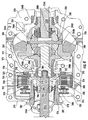
- FIG. 4 depicts a portion of a section view through the first axle assembly 210 of FIG. 3 at the engagement surface 228.
- the interior of the differential clutch carrier 220 is divided into two areas: a differential area 230 and a clutch area 232.
- the differential area 230 and the clutch area 232 are defined by the first and second carrier portion 222A, 222B (as seen in FIG. 3 ) and a partition 262. therein between the differential area 230 and the clutch area 232.
- the partition 262 is formed unitary with the first and second carrier portion 222A, 222B.
- the partition 262 divides the differential area 230 and the clutch area 232. However, an opening 264 extends from the differential area 230 to the clutch area 232 through the partition 262.
- the differential area 230 houses a differential assembly 234.
- the differential assembly 234 comprises a ring gear 236 in meshing engagement with the pinion gear.
- the ring gear 236 is coupled with a differential case 238, such as through mechanical fasteners and/or welding.
- the differential case 238 is mounted for rotation within the differential clutch carrier 220 with a pair of bearings 240A, 240B.
- the bearings 240A, 240B are disposed about a trunnion, or cylindrical protrusion, on opposing portions of the differential case 238 for support thereof inside the differential clutch carrier housing 220.
- the pinion gear rotates the ring gear 236 and through the connection of the ring gear 236 to the differential case 238, the differential case 238 rotates with the ring gear 236.
- the bearing 240A is disposed in a first diameter portion of the partition 262 opening 264.
- the bearing 240B is dipsoed in a first diameter portion of the differential clutch carrier 220 second opening 226B.
- the differential case 238 has a hollow interior.
- a spider shaft 242 extends through the hollow interior of the differntial case 238 and is coupled at a first end 244A and a second end 244B with the differential case 238.
- a first pinion gear 246A is mounted on the spider shaft first end 244A and a second pinion gear 246B is mounted on the spider shaft second end 244B.
- the pinion gears 246A, 246B are meshed with a first side gear 248A and a second side gear 248B within the differential case 238.
- the second side gear 248B is splined to the axle half shaft 251 B and the first side gear 248A is splined to a stub shaft 250.
- the stub shaft 250 extends from the differential area 230 to the clutch area 232 through the opening 264 in the partition 262.
- the differential assembly 234 may comprise four pinion gears in meshing engagement with a pair of side gears.
- the pinion gears may be mounted on a unitary cross type pin, a spider shaft and two additional pins, or four indpendent pins; the end of the pins and/or spidershaft may be coupled with a differential case, or may be coupled with a cannister insert housed inside the differential case.
- a wet-type clutch assembly 252 is located within the clutch area 232.
- the clutch assembly 252 comprises a drum portion 254 driveably enmeshed with splines on an outboard end of the stub shaft 250 for rotation therewith.
- the drum portion 254 comprises an axially extending center portion 300.
- the center portion 300 includes a cylindrical interior surface having splines meshed with the splines of the outboard end of the stub shaft 250.
- the drum portion 254 futher comprises a radially extending circular wall portion 302.
- the wall portion 302 is coupled with, and may be unitary with, the center portion 300.
- a plurality of apertures 290 extend axially through the drum portion 254 wall portion 300, substantially parallel with the axis of rotation of the stub shaft 250. In an embodiment, four apertures 290 are disposed in the wall poriton 300.
- the drum portion 254 additionally comprises an axially extending cylindrical portion 304.
- the cylindrical portion 304 is coupled with, and may be unitary with, the wall portion 302.
- a plurality of axially extending splines are formed on an internal surface of the cylindrical portion 304.
- a portion of the drum portion 254 center portion 300 is located within a second diameter portion of the partition 262 opening 264.
- the second diameter portion of the partition 262 opening 264 has a smaller diameter than the first diameter portion of the opening 264.
- the clutch assembly 252 also comprises a hub portion 256 substantially concentric with the drum portion 254.
- the hub portion 256 comprises an axially extending substantially cylindrical center portion 308 having a splined internal surface that is meshed with the spline on the axle half shaft 251A coupled with the wheel 114L.
- the hub portion 256 also comprises a radially extending wall portion 310 coupled with the inboard end of the center portion 308.
- the wall portion 310 may be formed unitary with the center portion 308.
- An axially extending cylindrical portion 312 is coupled at its inboard end with the outer edge of the wall portion 310.
- the cylindrical portion 312 may be formed unitary with the the wall portion 310.
- An outer surface of the cylindrical portion 312 comprises a plurality of axially extending splines.
- the hub portion 256 cylindrical portion 312 is concentric with the wall portion 310 and the center portion 308. As illustrated in FIG. 4 , in an embodiment, the hub portion 256 center portion 308, wall portion 310, and cylindrical portion 312 are located concentric with and inside the drum portion 254 cylindrical portion 304.
- the hub portion 256 cylindrical portion 312 has a first set of plates 258 coupled therewith for selective axial movement along the hub portion 256.
- the first set of plates 258 may include a plurality of splines or teeth on an internal circumference, or internal surface, thereof for engagement with the splines on the cylindrical portion 312.
- the first set of plates 258 extend radially outward from the hub portion 256.
- the drum portion 254 comprises a second set of plates 260 coupled therewith for selective axial movement along the drum portion 254.
- the second set of plates 260 may include a plurality of splines or teeth on a rim, or external surface, thereof for engagement with the splines on the cylindrical portion 304.
- the second set of plates 260 extends radially inward from the drum portion 254 cylindrical portion 304.
- the individual plates from the second set of plates 260 are interleaved with the individual plates from the first set of plates 258.
- the first and second set of plates 258, 260 comprise a clutch pack.
- the first set of plates 258 can be selectively frictionally engaged, and locked, with the second set of plates 260 when the plates are compressed together.
- the axial compression required to compress the plates together can be made through, for example, a ball and ramp actuator, a fluid driven piston, an electromagnetic structure, a mechanical structure, or other linear-type actuator indicated in FIG. 4 by reference numeral 316.
- the linear-type actuator 316 acts upon a pressure plate 318 in an axial direction.
- the pressure plate 318 is moved in an axial direction by the linear-type actuator 316 to frictionally engage the clutch pack.
- the first and second set of plates 258, 260 When frictionally engaged, the first and second set of plates 258, 260 prevent relative rotation between them, thus locking the axle half shaft 251A coupled with the wheel 114L for rotation with the differential side gear 248A.
- the first and second set of plates 258, 260 When the axial compression of the first and second set of clutch plates 258, 260 is relaxed, the first and second set of plates 258, 260 separate, thus disconnecting the axle half shaft 251A from the stub shaft 250.
- a first annular thrust bearing 306 is disposed between the clutch assembly 252 drum portion 254 wall portion 304 and the partition 262.
- a second annular thrust bearing 314 is located between the pressure plate 318 and the linear-type actuator 316.
- the thrust bearings 306, 316 assist in enabling rotation of the drum portion 254, and the pressure plate 318, when the clutch pack is engaged.
- the first annular thrust bearing 306 is substantially annular in geometry and is located radially outside the plurality of apertures 290.
- Cooling lubricant may therefore be circulated from the differential area 230 to the clutch area 232 to cool the clutch assembly 252.
- a first lubricant catch 266 may be located in the differential clutch carrier 220 first carrier portion engagement surface 228.
- the first lubricant catch 266 may also be defined by a portion of an interior wall of the first carrier portion 222A. More particularly, the first lubricant catch 266 may be cast into the differential clutch carrier 220 first carrier portion 222A engagement surface 228 and interior wall so that expensive post-casting machining is not required.
- the second carrier portion 222B may also define a portion of the first lubricant catch 266.
- the first lubricant catch 266 is located at an upper portion of the differential area 230. Particularly, the first lubricant catch 266 is substantially disposed adjacent to the outer circumference of the ring gear 236.
- the first lubricant catch 266 defines an inlet to a lubricant channel 268.
- the first lubricant catch 266 includes a portion outletting to the lubricant channel 268 and may extend downwardly from the upper portion of the differntial area 230.
- the first lubricant catch 266 may comprise an opening of a predetermined shape and size such as, but not limited to, a cotyloid, a longitudinal section of a funnel, a segment of a sphere or spheroid, or a substantially rectilinear body.
- the first lubricant catch 266 receives lubricant splashed or flung by the ring gear 236.
- the lubricant travels into the first lubricant catch 266, and from the first lubricant catch 266 into the lubricant channel 268.
- the lubricant channel 268 divides into a first lubricant channel 270 and a second lubricant channel 272.
- the first and second lubricant channels 270, 272 are disposed in the differential clutch carrier 220 first engagement surface 228 extending from the differential area 230 to the clutch area 232.
- the first and second lubricant channels 270, 272 extend through the partition 262 permitting unidirectional fluid communication between the differential area 230 and the clutch area 232.
- the lubricant channel 268 and the lubricant channels 270, 272 are disposed in the first engagement surface 228 of the differential clutch carrier 220 such that they are defined by a groove in the first engagement surface 222A and the second engagement surface of the second carrier portion 222B.
- the lubricant channel 268 and the lubricant channels 270, 272 are disposed in the first engagement surface 228 of the differential clutch carrier 220 such that they may be cast into the differential clutch carrier 220, obviating expensive secondary machining operations to create them.
- the lubricant channel 268 and the first and second lubricant channels 270, 272 may also be defined by a complimentary groove in the second engagement surface of the second carrier portion 222B.
- the differential clutch carrier 220 may comprise only the first lubricant channel 270. In another embodiment (not depicted), the differential clutch carrier 220 may comprise only the second lubricant channel 272.
- the first lubricant channel 270 extends off of the lubricant channel 268 substantially parallel to the axis of rotation of the differential assembly 234 and the axle half shafts 251A, 251 B.
- the first lubricant channel 270 is located at least partially above the clutch area 232 and turns radially inward toward the axis of rotation in an outer wall 274 of the differential clutch carrier 220.
- a substantially cylindrical bearing retainer 276 is disposed through the outer wall 274 of the differential clutch carrier 220 into the clutch area 232.
- the bearing retainer 276 comprises an annular body 278 having an extended portion 280.
- the extended portion 280 at least partially surrounds the clutch assembly 252 hub portion 256.
- the bearing retainer 276 comprises an annular shoulder 282.
- the annular shoulder 282 is engaged with an outside surface of the differential clutch carrier 220 outer wall 274 to position the bearing reatiner 276.
- the bearing retainer 276 further comprises an aperture 284 through the annular body 278.
- a bearing 286 is located at the interior of the bearing retainer 276 extended portion 280 and coupled therewith. The bearing 286 is also disposed about and coupled with the clutch assembly 252 hub portion 256, allowing rotation of the hub portion 256.
- the aperture 284 receives lubricant from the first lubricant channel 270.
- the lubricant may then pass through the bearing 286, placing the first lubricant channel 270 in fluid communication with the clutch assembly 252 hub portion 256.
- the lubricant flows radially outward through the first set of plates 258 of the hub portion 256.
- the rotation of the hub portion 256 forces the lubricant radially outward as a result of centrifugal force.
- the lubricant flows through the first set of clutch plates 258 and the second set of clutch plates 260, where the lubricant absorbs heat from the plates 258, 260, thereby cooling them.
- the lubricant flowing through the clutch plates 258, 260 then collects in a clutch area 232 lubricant sump 288.
- the second lubricant channel 272 extends off of the lubricant channel 268 in a downward diagonal direction toward the axis of rotation of the differential assembly 234 and the axle half shafts 251A, 251 B. As illustrated in FIG. 4 , the second lubricant channel 272 extends in the first engagement surface 228 of the differential clutch carrier 220 partition 262 separating the differential area 230 from the clutch area 232. The second lubricant channel 272 is in fluid communication with the clutch assembly 252 via the plurality of apertures 290, in the drum portion 254 wall portion 300 of the clutch assembly 252. Lubricant passes through the second lubricant channel 272, through the drum portion 254 to the hub portion 256. The lubricant then communicates with the clutch plates 258, 260 as described above.
- Lubricant may be delivered to the clutch assembly 252 with one or both of the above-described first and second lubricant channels 270, 272. While two lubricant channels have been described and depicted, one may be eliminated if desired.
- the clutch area 232 lubricant sump 288, located at the bottom of the clutch area 232, comprises a return channel 292 that is cast into the differential clutch carrier 220 first carrier portion 222A.
- the return channel 292 may be such as an axially extending groove, parallel to the axis of rotation of the differential assembly 234, in fluid communication with the clutch assembly 252.
- the return channel 292 may extend the axial length of the clutch assembly 252 in the clutch area 232 lubricant sump 288 to capture lubricant from the clutch assembly 252.
- a second lubricant catch 293 is formed unitary with a portion of the return channel 292.
- the second lubricant catch 293 is disposed substantially tangential with the exterior surface of the clutch assembly 252 drum portion 254 cylindrical portion 256.
- the second lubricant catch 293 may comprise a geometry substantially similar to a hollow right circular cylinder positioned such that the hollow portion of the lubricant catch 293 faces the same direction as the first engagement surface 228.
- the second lubricant catch 293 may comprise a groove in the first engagement surface 228.
- the second lubricant catch 293 functions to scrape lubricate from the exterior surface of the clutch assembly 252 drum portion 254 cylindrical portion 256.
- the second lubricant catch 293 functions to catch, or collect, lubricant moved or flung by the exterior surface of the clutch assembly 252 drum portion 254 cylindrical portion 256.
- the return channel 292 may include a third lubricant catch disposed opposite the second lubricant catch 293 in the clutch area 232 lubricant sump 288.
- the third lubricant catch may substantially mirror the second lubricant catch 293, and include a conduit in fluid communication with the return channel 292.
- the lubricant sump 288 may also comprise radially extending protrusions 294 disposed upwardly along the differential clutch carrier 220 interior wall.
- the protrusions 294 may follow the slope of the differential clutch carrier 220 wall as it extends upwardly from the bottom of the clutch area 232.
- the protrusions 294 define one or more reservoirs 296 located within the lubricant sump 288.
- the reservoirs 296 may be axially spaced apart from one another.
- the protrusion 294 and the reservoirs 296 contribute to control of the lubricant and function to reduce the extreme axial movement of the lubricant in the lubricant sump 288.
- the lubricant sump 288, the second lubricant catch 293, the reservoirs 296, and the drum portion 254 of the clutch assembly 252 comprise a lubricant circulating device, or pump mechanism, which delivers lubricant to the differential area 230.
- the lubricant circulating device generates a pumping action when the clutch assembly 252 is not engaged and the drum portion 254 rotates in the opposite direction of the rotating axle half shaft 251A.
- the friction created by the exterior surface of the drum portion 254 rotating through the lubricant in the clutch area 232 lubricant sump 288 serves to move the lubricant into the return channel 292.
- the lubricant circulating device also actively moves lubricant into the second lubricant catch 293 and the return channel 292 when the clutch assembly 252 is engaged and the drum portion 254 rotates in the direction of the rotating axle half shaft 251A.
- the third lubricant catch when the clutch assembly 252 is engaged and the drum portion 254 rotates in the direction of the rotating axle half shaft 251A, the third lubricant catch primarily collects lubricant and delivers the lubricant to the return channel 292. Regardless of the direction of the rotation, the rotating clutch assembly 252 drum portion 254 moves the lubricant from the lubricant sump 288 through the return channel 292.
- the lubricant is moved through the return channel 292 which connects the lubricant sump 288 to the differential area 230 lubricant sump.
- the return channel 292 is parallel with the rotational axis of the differential assembly 234 and is located through the differential clutch carrier 220 partition 262 below the stub shaft.
- the return channel 292 is cast into the first carrier portion 222A engagement surface 228, thus eliminating the need for a further machining step.
- the return channel 292 is best seen in FIGS. 4-6 .
- the return channel 292 opens into the differential area 230 adjacent the ring gear 236.
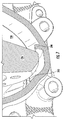
- a radially inward extending rib 298 is located adjacent the ring gear 236. See FIGS. 4 and 6 . More particularly, the rib 298 is located in the bottom portion of the differential area 230 lubricant sump, and extends along the interior wall of the differential area 230.
- the rib 298 may be formed in both the first and second carrier portions 222A, 222B. Being so located near the ring gear 236, as the ring gear 236 rotates past the rib 298 a low pressure area 300 is created between the return channel 292 and the rib 298.
- the low pressure assists in drawing the lubricant from the clutch area 232, through the return channel 292, and into the differential area 230.
- the rib 298, the ring gear 236, and the differential area 230 comprise another active lubricant circulating device.
- the returning lubricant is mixed with the lubricant in the differential area 230 and cooled.
- the lubricant in the differential area 230 may then be used to cool and lubricate the parts in the differential area 230, or flung into the first lubricant catch 266.
Landscapes
- Engineering & Computer Science (AREA)
- General Engineering & Computer Science (AREA)
- Mechanical Engineering (AREA)
- Chemical & Material Sciences (AREA)
- Combustion & Propulsion (AREA)
- Transportation (AREA)
- General Details Of Gearings (AREA)
- Retarders (AREA)
Abstract
Description
- The present application claims the benefit to
U.S. Provisional Application No. 62/184,312 filed on June 25, 2015 - The present subject matter relates to a driving force distribution apparatus. A driving force distribution apparatus may include a differential assembly and a clutch assembly to transmit drive force. The driving force distribution apparatus may further include a lubrication system. The lubrication system may provide lubrication and cooling of the clutch assembly. Conventional driving force distribution apparatus create concern for the effectiveness of the clutch assembly lubrication and the system drag torque.
- In view of the above, there remains a need for a driving force distribution apparatus having increased system efficiency.
- An axle assembly for a vehicle including a differential carrier having a first portion and a second portion. The first portion including a first engagement surface coupled with a second engagement surface of the second portion. The differential carrier defines a differential area and a clutch area substantially separated by a partition. The differential carrier first engagement surface defines a lubricant channel fluidly connecting the differential area with the clutch area. The lubricant channel is at least partially located above the clutch area, and bending such that the lubricant channel is at least partially located in an outer wall of the differential carrier. The axle assembly further includes a bearing retainer disposed through the outer wall of the differential carrier. The bearing retainer includes an aperture therethrough, fluidly connecting the lubricant channel with a clutch assembly.
- The axle assembly may also include a first lubricant circulating device in the differential area, and/or a second lubricant circulating device in the clutch area.
- The accompanying drawings are incorporated herein as part of the specification. The drawings described herein illustrate embodiments of the presently disclosed subject matter, and are illustrative of selected principles and teachings of the present disclosure and do not illustrate all possible implementations thereof. The drawings are not intended to limit the scope of the present disclosure in any way.
-
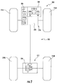
FIG. 1 is a schematic diagram of a portion of a powertrain according to an embodiment of the presently disclosed subject matter; -
FIG. 2 is another schematic diagram of a portion of a powertrain according to an embodiment of the presently disclosed subject matter; -
FIG. 3 is a perspective view of a portion of the driveline ofFIG. 2 ; -
FIG. 4 is a cross-sectional view of a portion of the driveline ofFIG. 3 ; -
FIG. 5 is another cross-sectional view of a portion of the driveline ofFIG. 3 ; -
FIG. 6 is another cross-sectional view of a portion of the driveline ofFIG. 3 ; and -
FIG. 7 is yet another cross-sectional view of a portion of the driveline ofFIG. 3 . - It is to be understood that the invention may assume various alternative orientations and step sequences, except where expressly specified to the contrary. It is also to be understood that the specific assemblies and systems illustrated in the attached drawings, and described in the following specification are simply exemplary embodiments of the inventive concepts defined herein. Hence, specific dimensions, directions or other physical characteristics relating to the embodiments disclosed are not to be considered as limiting, unless expressly stated otherwise. Also, although they may not be, like elements in various embodiments described herein may be commonly referred to with like reference numerals within this section of the application.
- As illustrated in
FIG. 1 , a vehicle having a first axle assembly constructed in accordance with the teachings of the present disclosure is generally indicated byreference numeral 100. Thevehicle 100 may comprise apowertrain 102 having all-wheel drive functionality. Thepowertrain 102 may include apower source 104 having an output driveably connected with atransmission 106 input. Thepower source 104 may be, but is not limited to, an internal combustion engine or an electric motor. In one embodiment, as illustrated inFIG. 1 , thepowertrain 102 may include atransfer case 108 driveably connected to an output of thetransmission 106, afirst axle assembly 110, and asecond axle assembly 112. Thefirst axle assembly 110 is driveably connected with thetransmission 106 and continuously transmits torque from anengine 104 to a pair ofrear wheels second axle assembly 112 selectively transmitsengine 104 torque to a pair offront wheels transfer case 108. Thefront axle assembly 110 includes a differential clutch carrier 120. - As illustrated in
FIG. 2 , a vehicle having a first axle assembly constructed in accordance with the teachings of the present disclosure is generally indicated byreference numeral 200. Thevehicle 200 may comprise apowertrain 202 having all-wheel drive functionality. Thepowertrain 202 may include apower source 204 having an output driveably connected with atransmission 206 input. Thepower source 204 may be, but is not limited to, an internal combustion engine or an electric motor. Thepowertrain 202 may include afirst axle assembly 210. In one embodiment, as illustrated inFIG. 2 , thefirst axle assembly 210 comprises apower transfer unit 208 driveably connected with an output of thetransmission 206. Thepowertrain 202 may also include asecond axle assembly 212. Thefirst axle assembly 210 is driveably connected with thetransmission 206 and continuously transmitspower source 204 torque to a pair offront wheels second axle assembly 212 selectively transmitspower source 204 torque to a pair ofrear wheels 214L, 214R via thepower transfer unit 208. Thesecond axle assembly 212 includes adifferential clutch carrier 220. - Turning to
FIG. 3 , one embodiment of thedifferential clutch carrier 220 is depicted. However, the invention is not limited to the carrier as shown inFIG. 3 . Instead, the present subject matter may be utilized with carriers of other shapes, sizes, orientations and designs. - As illustrated in
FIGS. 3 and4 , thedifferential clutch carrier 220 comprises a two piece differential carrier, thefirst carrier portion 222A and thesecond carrier portion 222B. Thefirst carrier portion 222A has anengagement surface 228 and thesecond carrier portion 228 includes a complimentary engagement surface (not depicted). The first andsecond carrier portions - The
first axle assembly 210 includes apinion shaft 224 and a pinion gear (not depicted) for receiving rotation from thepower source 204. Thefirst axle assembly 210differential clutch carrier 220 comprises two opposed openings through which axlehalf shafts axle half shaft 251A extends through the first opening 226A, and theaxle half shaft 251 B extends through the second opening 226B. Theopposed openings pinion shaft 224. Theaxle half shafts rear wheels 214L, 214R. -
FIG. 4 depicts a portion of a section view through thefirst axle assembly 210 ofFIG. 3 at theengagement surface 228. As illustrated inFIG. 4 , the interior of thedifferential clutch carrier 220 is divided into two areas: adifferential area 230 and aclutch area 232. Thedifferential area 230 and theclutch area 232 are defined by the first andsecond carrier portion FIG. 3 ) and apartition 262. therein between thedifferential area 230 and theclutch area 232. - As illustrated in
FIG. 4 , in an embodiment, thepartition 262 is formed unitary with the first andsecond carrier portion partition 262 divides thedifferential area 230 and theclutch area 232. However, an opening 264 extends from thedifferential area 230 to theclutch area 232 through thepartition 262. - The
differential area 230 houses adifferential assembly 234. Thedifferential assembly 234 comprises aring gear 236 in meshing engagement with the pinion gear. Thering gear 236 is coupled with adifferential case 238, such as through mechanical fasteners and/or welding. - The
differential case 238 is mounted for rotation within the differentialclutch carrier 220 with a pair ofbearings bearings differential case 238 for support thereof inside the differentialclutch carrier housing 220. The pinion gear rotates thering gear 236 and through the connection of thering gear 236 to thedifferential case 238, thedifferential case 238 rotates with thering gear 236. - The bearing 240A is disposed in a first diameter portion of the
partition 262 opening 264. The bearing 240B is dipsoed in a first diameter portion of the differentialclutch carrier 220second opening 226B. - The
differential case 238 has a hollow interior. Aspider shaft 242 extends through the hollow interior of thedifferntial case 238 and is coupled at afirst end 244A and asecond end 244B with thedifferential case 238. Afirst pinion gear 246A is mounted on the spider shaftfirst end 244A and asecond pinion gear 246B is mounted on the spider shaftsecond end 244B. The pinion gears 246A, 246B are meshed with afirst side gear 248A and asecond side gear 248B within thedifferential case 238. Thesecond side gear 248B is splined to theaxle half shaft 251 B and thefirst side gear 248A is splined to astub shaft 250. Thestub shaft 250 extends from thedifferential area 230 to theclutch area 232 through the opening 264 in thepartition 262. - In another embodiment, not depicted, the
differential assembly 234 may comprise four pinion gears in meshing engagement with a pair of side gears. The pinion gears may be mounted on a unitary cross type pin, a spider shaft and two additional pins, or four indpendent pins; the end of the pins and/or spidershaft may be coupled with a differential case, or may be coupled with a cannister insert housed inside the differential case. - As illustrated in
FIG. 4 , a wet-typeclutch assembly 252 is located within theclutch area 232. Theclutch assembly 252 comprises adrum portion 254 driveably enmeshed with splines on an outboard end of thestub shaft 250 for rotation therewith. Thedrum portion 254 comprises an axially extendingcenter portion 300. Thecenter portion 300 includes a cylindrical interior surface having splines meshed with the splines of the outboard end of thestub shaft 250. Thedrum portion 254 futher comprises a radially extendingcircular wall portion 302. Thewall portion 302 is coupled with, and may be unitary with, thecenter portion 300. A plurality ofapertures 290 extend axially through thedrum portion 254wall portion 300, substantially parallel with the axis of rotation of thestub shaft 250. In an embodiment, fourapertures 290 are disposed in thewall poriton 300. Thedrum portion 254 additionally comprises an axially extendingcylindrical portion 304. Thecylindrical portion 304 is coupled with, and may be unitary with, thewall portion 302. A plurality of axially extending splines are formed on an internal surface of thecylindrical portion 304. - A portion of the
drum portion 254center portion 300 is located within a second diameter portion of thepartition 262 opening 264. The second diameter portion of thepartition 262 opening 264 has a smaller diameter than the first diameter portion of the opening 264. - The
clutch assembly 252 also comprises ahub portion 256 substantially concentric with thedrum portion 254. Thehub portion 256 comprises an axially extending substantiallycylindrical center portion 308 having a splined internal surface that is meshed with the spline on theaxle half shaft 251A coupled with thewheel 114L. Thehub portion 256 also comprises a radially extendingwall portion 310 coupled with the inboard end of thecenter portion 308. In certain embodiments, thewall portion 310 may be formed unitary with thecenter portion 308. An axially extendingcylindrical portion 312 is coupled at its inboard end with the outer edge of thewall portion 310. In an embodiment, thecylindrical portion 312 may be formed unitary with the thewall portion 310. An outer surface of thecylindrical portion 312 comprises a plurality of axially extending splines. - The
hub portion 256cylindrical portion 312 is concentric with thewall portion 310 and thecenter portion 308. As illustrated inFIG. 4 , in an embodiment, thehub portion 256center portion 308,wall portion 310, andcylindrical portion 312 are located concentric with and inside thedrum portion 254cylindrical portion 304. - The
hub portion 256cylindrical portion 312 has a first set ofplates 258 coupled therewith for selective axial movement along thehub portion 256. The first set ofplates 258 may include a plurality of splines or teeth on an internal circumference, or internal surface, thereof for engagement with the splines on thecylindrical portion 312. The first set ofplates 258 extend radially outward from thehub portion 256. - The
drum portion 254 comprises a second set ofplates 260 coupled therewith for selective axial movement along thedrum portion 254. The second set ofplates 260 may include a plurality of splines or teeth on a rim, or external surface, thereof for engagement with the splines on thecylindrical portion 304. The second set ofplates 260 extends radially inward from thedrum portion 254cylindrical portion 304. The individual plates from the second set ofplates 260 are interleaved with the individual plates from the first set ofplates 258. The first and second set ofplates - The first set of
plates 258 can be selectively frictionally engaged, and locked, with the second set ofplates 260 when the plates are compressed together. The axial compression required to compress the plates together can be made through, for example, a ball and ramp actuator, a fluid driven piston, an electromagnetic structure, a mechanical structure, or other linear-type actuator indicated inFIG. 4 byreference numeral 316. The linear-type actuator 316 acts upon apressure plate 318 in an axial direction. Thepressure plate 318 is moved in an axial direction by the linear-type actuator 316 to frictionally engage the clutch pack. - When frictionally engaged, the first and second set of
plates axle half shaft 251A coupled with thewheel 114L for rotation with thedifferential side gear 248A. When the axial compression of the first and second set ofclutch plates plates axle half shaft 251A from thestub shaft 250. - A first
annular thrust bearing 306 is disposed between theclutch assembly 252drum portion 254wall portion 304 and thepartition 262. A secondannular thrust bearing 314 is located between thepressure plate 318 and the linear-type actuator 316. Thethrust bearings drum portion 254, and thepressure plate 318, when the clutch pack is engaged. The firstannular thrust bearing 306 is substantially annular in geometry and is located radially outside the plurality ofapertures 290. - The above-described frictional engagement of the
clutch assembly 252 generates an appreciable amount of heat. It has been found that theclutch assembly 252 cannot function at the desired efficiency while experiencing elevated temperatures, and/or the heat can cause theclutch assebmly 252 to prematurely fail. - Cooling lubricant may therefore be circulated from the
differential area 230 to theclutch area 232 to cool theclutch assembly 252. As illustrated inFIG. 4 , in an embodiment, afirst lubricant catch 266 may be located in the differentialclutch carrier 220 first carrierportion engagement surface 228. Thefirst lubricant catch 266 may also be defined by a portion of an interior wall of thefirst carrier portion 222A. More particularly, thefirst lubricant catch 266 may be cast into the differentialclutch carrier 220first carrier portion 222A engagement surface 228 and interior wall so that expensive post-casting machining is not required. In an embodiment, thesecond carrier portion 222B may also define a portion of thefirst lubricant catch 266. - In the depicted embodiment, the
first lubricant catch 266 is located at an upper portion of thedifferential area 230. Particularly, thefirst lubricant catch 266 is substantially disposed adjacent to the outer circumference of thering gear 236. Thefirst lubricant catch 266 defines an inlet to alubricant channel 268. Thefirst lubricant catch 266 includes a portion outletting to thelubricant channel 268 and may extend downwardly from the upper portion of thedifferntial area 230. Thefirst lubricant catch 266 may comprise an opening of a predetermined shape and size such as, but not limited to, a cotyloid, a longitudinal section of a funnel, a segment of a sphere or spheroid, or a substantially rectilinear body. - The
first lubricant catch 266 receives lubricant splashed or flung by thering gear 236. The lubricant travels into thefirst lubricant catch 266, and from thefirst lubricant catch 266 into thelubricant channel 268. In the depicted embodiment, thelubricant channel 268 divides into afirst lubricant channel 270 and asecond lubricant channel 272. - The first and
second lubricant channels clutch carrier 220first engagement surface 228 extending from thedifferential area 230 to theclutch area 232. The first andsecond lubricant channels partition 262 permitting unidirectional fluid communication between thedifferential area 230 and theclutch area 232. Thelubricant channel 268 and thelubricant channels first engagement surface 228 of the differentialclutch carrier 220 such that they are defined by a groove in thefirst engagement surface 222A and the second engagement surface of thesecond carrier portion 222B. Thelubricant channel 268 and thelubricant channels first engagement surface 228 of the differentialclutch carrier 220 such that they may be cast into the differentialclutch carrier 220, obviating expensive secondary machining operations to create them. In an embodiment, thelubricant channel 268 and the first andsecond lubricant channels second carrier portion 222B. - In an embodiment (not depicted), the differential
clutch carrier 220 may comprise only thefirst lubricant channel 270. In another embodiment (not depicted), the differentialclutch carrier 220 may comprise only thesecond lubricant channel 272. - The
first lubricant channel 270 extends off of thelubricant channel 268 substantially parallel to the axis of rotation of thedifferential assembly 234 and theaxle half shafts first lubricant channel 270 is located at least partially above theclutch area 232 and turns radially inward toward the axis of rotation in anouter wall 274 of the differentialclutch carrier 220. - A substantially
cylindrical bearing retainer 276 is disposed through theouter wall 274 of the differentialclutch carrier 220 into theclutch area 232. The bearingretainer 276 comprises anannular body 278 having anextended portion 280. Theextended portion 280 at least partially surrounds theclutch assembly 252hub portion 256. Opposite theextended portion 280, the bearingretainer 276 comprises anannular shoulder 282. Theannular shoulder 282 is engaged with an outside surface of the differentialclutch carrier 220outer wall 274 to position thebearing reatiner 276. The bearingretainer 276 further comprises anaperture 284 through theannular body 278. Abearing 286 is located at the interior of the bearingretainer 276extended portion 280 and coupled therewith. Thebearing 286 is also disposed about and coupled with theclutch assembly 252hub portion 256, allowing rotation of thehub portion 256. - The
aperture 284 receives lubricant from thefirst lubricant channel 270. The lubricant may then pass through thebearing 286, placing thefirst lubricant channel 270 in fluid communication with theclutch assembly 252hub portion 256. Once through thebearing 286, the lubricant flows radially outward through the first set ofplates 258 of thehub portion 256. The rotation of thehub portion 256 forces the lubricant radially outward as a result of centrifugal force. The lubricant flows through the first set ofclutch plates 258 and the second set ofclutch plates 260, where the lubricant absorbs heat from theplates clutch plates clutch area 232lubricant sump 288. - The
second lubricant channel 272 extends off of thelubricant channel 268 in a downward diagonal direction toward the axis of rotation of thedifferential assembly 234 and theaxle half shafts 251A, 251 B. As illustrated inFIG. 4 , thesecond lubricant channel 272 extends in thefirst engagement surface 228 of the differentialclutch carrier 220partition 262 separating thedifferential area 230 from theclutch area 232. Thesecond lubricant channel 272 is in fluid communication with theclutch assembly 252 via the plurality ofapertures 290, in thedrum portion 254wall portion 300 of theclutch assembly 252. Lubricant passes through thesecond lubricant channel 272, through thedrum portion 254 to thehub portion 256. The lubricant then communicates with theclutch plates - Lubricant may be delivered to the
clutch assembly 252 with one or both of the above-described first andsecond lubricant channels - As shown in
FIGS. 4 and5 , theclutch area 232lubricant sump 288, located at the bottom of theclutch area 232, comprises areturn channel 292 that is cast into the differentialclutch carrier 220first carrier portion 222A. Thereturn channel 292 may be such as an axially extending groove, parallel to the axis of rotation of thedifferential assembly 234, in fluid communication with theclutch assembly 252. Thereturn channel 292 may extend the axial length of theclutch assembly 252 in theclutch area 232lubricant sump 288 to capture lubricant from theclutch assembly 252. In the depicted embodiment, asecond lubricant catch 293 is formed unitary with a portion of thereturn channel 292. Thesecond lubricant catch 293 is disposed substantially tangential with the exterior surface of theclutch assembly 252drum portion 254cylindrical portion 256. In an embodiment, thesecond lubricant catch 293 may comprise a geometry substantially similar to a hollow right circular cylinder positioned such that the hollow portion of thelubricant catch 293 faces the same direction as thefirst engagement surface 228. In another embodiment, thesecond lubricant catch 293 may comprise a groove in thefirst engagement surface 228. In certain embodiments, thesecond lubricant catch 293 functions to scrape lubricate from the exterior surface of theclutch assembly 252drum portion 254cylindrical portion 256. In other embodiments, thesecond lubricant catch 293 functions to catch, or collect, lubricant moved or flung by the exterior surface of theclutch assembly 252drum portion 254cylindrical portion 256. - In an embodiment, not depicted, the
return channel 292 may include a third lubricant catch disposed opposite thesecond lubricant catch 293 in theclutch area 232lubricant sump 288. The third lubricant catch may substantially mirror thesecond lubricant catch 293, and include a conduit in fluid communication with thereturn channel 292. - The
lubricant sump 288 may also comprise radially extendingprotrusions 294 disposed upwardly along the differentialclutch carrier 220 interior wall. Theprotrusions 294 may follow the slope of the differentialclutch carrier 220 wall as it extends upwardly from the bottom of theclutch area 232. Theprotrusions 294 define one ormore reservoirs 296 located within thelubricant sump 288. Thereservoirs 296 may be axially spaced apart from one another. Theprotrusion 294 and thereservoirs 296 contribute to control of the lubricant and function to reduce the extreme axial movement of the lubricant in thelubricant sump 288. - The
lubricant sump 288, thesecond lubricant catch 293, thereservoirs 296, and thedrum portion 254 of theclutch assembly 252 comprise a lubricant circulating device, or pump mechanism, which delivers lubricant to thedifferential area 230. The lubricant circulating device generates a pumping action when theclutch assembly 252 is not engaged and thedrum portion 254 rotates in the opposite direction of the rotating axlehalf shaft 251A. The friction created by the exterior surface of thedrum portion 254 rotating through the lubricant in theclutch area 232lubricant sump 288 serves to move the lubricant into thereturn channel 292. The lubricant circulating device also actively moves lubricant into thesecond lubricant catch 293 and thereturn channel 292 when theclutch assembly 252 is engaged and thedrum portion 254 rotates in the direction of the rotating axlehalf shaft 251A. - In an embodiment having the third lubricant catch, when the
clutch assembly 252 is engaged and thedrum portion 254 rotates in the direction of the rotating axlehalf shaft 251A, the third lubricant catch primarily collects lubricant and delivers the lubricant to thereturn channel 292. Regardless of the direction of the rotation, the rotatingclutch assembly 252drum portion 254 moves the lubricant from thelubricant sump 288 through thereturn channel 292. - The lubricant is moved through the
return channel 292 which connects thelubricant sump 288 to thedifferential area 230 lubricant sump. Thereturn channel 292 is parallel with the rotational axis of thedifferential assembly 234 and is located through the differentialclutch carrier 220partition 262 below the stub shaft. Thereturn channel 292 is cast into thefirst carrier portion 222A engagement surface 228, thus eliminating the need for a further machining step. Thereturn channel 292 is best seen inFIGS. 4-6 . - The
return channel 292 opens into thedifferential area 230 adjacent thering gear 236. A radially inward extendingrib 298 is located adjacent thering gear 236. SeeFIGS. 4 and6 . More particularly, therib 298 is located in the bottom portion of thedifferential area 230 lubricant sump, and extends along the interior wall of thedifferential area 230. Therib 298 may be formed in both the first andsecond carrier portions ring gear 236, as thering gear 236 rotates past the rib 298 alow pressure area 300 is created between thereturn channel 292 and therib 298. The low pressure assists in drawing the lubricant from theclutch area 232, through thereturn channel 292, and into thedifferential area 230. Therib 298, thering gear 236, and thedifferential area 230 comprise another active lubricant circulating device. The returning lubricant is mixed with the lubricant in thedifferential area 230 and cooled. The lubricant in thedifferential area 230 may then be used to cool and lubricate the parts in thedifferential area 230, or flung into thefirst lubricant catch 266. - A person skilled in the relevant art will recognize that the subject matter disclosed herein may also be utilized with, but is not limited to use with, a locking differential.
- While various embodiments have been described above, it should be understood that they have been presented by way of example, and not limitation. It will be apparent to persons skilled in the relevant art(s) that the disclosed subject matter may be embodied in other specific forms without departing from the spirit or essential characteristics thereof. The embodiments described above are therefore to be considered in all respects as illustrative, not restrictive.
Claims (13)
- An axle assembly, comprising:a differential carrier comprising a first portion and a second portion;said first portion including a first engagement surface,said second portion including a second engagement surface coupled with said first engagement surface,said differential carrier first and second portions defining a differential area and a clutch area;said differential area and said clutch area substantially separated by a partition;said differential carrier first engagement surface including a lubricant channel fluidly connecting said differential area with said clutch area,said lubricant channel at least partially disposed above said clutch area, wherein said lubricant channel includes a bend disposing said lubricant channel at least partially in an outer wall of said differential carrier first portion,a substantially cylindrical bearing retainer disposed through said outer wall of said differential carrier,said bearing retainer extending into said clutch area, andsaid bearing retainer having an aperture therethrough, whereby said lubricant channel is in fluid connection with said clutch assembly.
- The axle assembly according to claim 1, wherein
said lubricant channel is at least partially disposed above said clutch area, and includes a bend disposing said lubricant channel at least partially in an outer wall of said differential carrier first portion. - The axle assembly according to one of the preceding claims, wherein
said lubricant channel is at least partially disposed in a downward diagonal direction through said partition to said clutch area. - The axle assembly according to one of the preceding claims, wherein
said lubricant channel divides into a first lubricant channel and a second lubricant channel,
said first lubricant channel at least partially disposed above said clutch area, and including a bend disposing said first lubricant channel at least partially in an outer wall of said differential carrier first portion, and
said second lubricant channel at least partially disposed in a downward diagonal direction through said partition to said clutch area. - The axle assembly according to one of the preceding claims, wherein
said clutch area defines a lubricant sump,
said clutch area lubricant sump includes at least two radially extending protrusions disposed upwardly along an interior wail of said differential carrier, and
said differential carrier first engagement surface includes a return channel fluidly connecting said clutch area lubricant sump with said differential area. - The axle assembly of claim 5, wherein
said differential area defines a lubricant sump, and
said differential area lubricant sump defines an outlet of said return channel. - The axle assembly according to one of the preceding claims, wherein
said differential area houses a differential assembly, comprising,a differential case,a ring gear coupled with said differential case, wherein said ring gear receives driving force from a pinion gear,a pair of pinion gears housed within said differential case,a pair of side gears engaged with said pinion gears,a stub shaft splined with one of said pair of side gears, anda first axle half shaft splined with one of said pair of side gears. - The axle assembly of claim 7, wherein
said clutch area houses a clutch assembly, comprising,a drum portion splined with said stub shaft,a hub portion splined with a second axle half shaft,a first set of clutch plates coupled with said hub portion, anda second set of clutch plates coupled with said drum portion. - The axle assembly according to one of claims 6 to 8, wherein
said differential area lubricant sump includes a radially inward extending rib, said rib disposed adjacent to said return channel outlet. - The axle assembly of claim 9, further comprising
a first lubricant circulating device comprising:said ring gear at least partially disposed between said return channel outlet andsaid differential area lubricant sump rib. - The axle assembly according to claim 5 and according to one of claims 8 to 10, further comprising
a second lubricant circulating device comprising:said clutch assembly drum portion,said clutch area lubricant sump, andsaid clutch area lubricant sump at least two radially extending protrusions. - The axle assembly according to one of claims 8 to 11, wherein
said clutch assembly drum portion defines at least one aperture therethrough, and
said lubricant channel is in fluid communication with said drum portion at least one aperture. - The axle assembly according to claim 4 and according to one of claims 8 to 12, wherein
said clutch assembly drum portion defines at least one aperture therethrough, and
said second lubricant channel is in fluid communication with said drum portion at least one aperture.
Applications Claiming Priority (1)
| Application Number | Priority Date | Filing Date | Title |
|---|---|---|---|
| US201562184312P | 2015-06-25 | 2015-06-25 |
Publications (3)
| Publication Number | Publication Date |
|---|---|
| EP3109513A2 true EP3109513A2 (en) | 2016-12-28 |
| EP3109513A3 EP3109513A3 (en) | 2017-02-15 |
| EP3109513B1 EP3109513B1 (en) | 2019-12-18 |
Family
ID=56740768
Family Applications (1)
| Application Number | Title | Priority Date | Filing Date |
|---|---|---|---|
| EP16176356.0A Active EP3109513B1 (en) | 2015-06-25 | 2016-06-27 | Differential clutch carrier lubrication and cooling system |
Country Status (2)
| Country | Link |
|---|---|
| US (1) | US9885415B2 (en) |
| EP (1) | EP3109513B1 (en) |
Cited By (2)
| Publication number | Priority date | Publication date | Assignee | Title |
|---|---|---|---|---|
| US20170175876A1 (en) * | 2015-12-16 | 2017-06-22 | Toyota Jidosha Kabushiki Kaisha | Differential gear |
| EP3842666A1 (en) * | 2019-12-26 | 2021-06-30 | Valeo Embrayages | Electric powertrain with two clutches |
Families Citing this family (8)
| Publication number | Priority date | Publication date | Assignee | Title |
|---|---|---|---|---|
| DE102013018710A1 (en) | 2013-11-08 | 2015-05-13 | Sew-Eurodrive Gmbh & Co Kg | Gearbox with housing |
| US9797502B2 (en) * | 2016-03-23 | 2017-10-24 | Arvinmeritor Technology, Llc | Axle assembly having a lubricant reservoir |
| US10357997B1 (en) * | 2018-02-20 | 2019-07-23 | Arvinmeritor Technology, Llc | Drive axle assembly with moveable axle shaft and method of operation |
| US11242899B2 (en) * | 2018-06-06 | 2022-02-08 | Dana Automotive Systems Group, Llc | Fluid distribution apparatus and the axle assembly made therewith |
| JP2020165443A (en) * | 2019-03-28 | 2020-10-08 | 株式会社ジェイテクト | Differential device and product group of differential device |
| US10968793B1 (en) * | 2019-10-24 | 2021-04-06 | Dana Automotive Systems Group, Llc | Axle assembly |
| US11668391B2 (en) * | 2020-02-26 | 2023-06-06 | Dana Heavy Vehicle Systems Group, Llc | Vehicle drivetrain with interaxle differential and method for drivetrain operation |
| US11255424B2 (en) * | 2020-03-09 | 2022-02-22 | Arvinmeritor Technology, Llc | Axle assembly having an internal lubricant passage |
Family Cites Families (21)
| Publication number | Priority date | Publication date | Assignee | Title |
|---|---|---|---|---|
| US3762503A (en) | 1971-04-14 | 1973-10-02 | Eaton Yale & Towne | Lubrication system for limited slip differential |
| US3741343A (en) | 1971-04-29 | 1973-06-26 | Clark Equipment Co | Lubrication system for a differential |
| JP2747165B2 (en) * | 1992-05-06 | 1998-05-06 | 栃木富士産業株式会社 | Differential device |
| US5536215A (en) * | 1993-02-10 | 1996-07-16 | Asha Corporation | Hydraulic coupling for vehicle drivetrain |
| CA2133136A1 (en) | 1993-10-14 | 1995-04-15 | Gregory T. Dewald | Differential |
| HU216712B (en) | 1994-02-24 | 1999-08-30 | RÁBA Magyar Vagon- és Gépgyár Rt. | Special circulating device of, lubricant-oil for cooling of running gears of machines and heary loaded planet-running gears |
| JP2002195384A (en) | 2000-10-19 | 2002-07-10 | Tochigi Fuji Ind Co Ltd | Differential device |
| JP4350702B2 (en) | 2005-12-14 | 2009-10-21 | 株式会社オーエス技研 | Differential |
| DE112006000026T5 (en) | 2006-05-19 | 2008-07-24 | Gkn Driveline Torque Technology Kk | Driving force transmitting device |
| US8382628B2 (en) | 2007-07-17 | 2013-02-26 | American Axle & Manufacturing, Inc. | Method and apparatus for lubricating a differential in an axle assembly |
| US20090093333A1 (en) * | 2007-10-08 | 2009-04-09 | Adams Iii Herbert L | Axle assembly with electro-hydraulic clutch control system |
| US20100304914A1 (en) | 2009-05-28 | 2010-12-02 | Barrett Mark S | Limited slip differential with positive lube flow to clutch plates |
| US8475314B2 (en) | 2010-01-28 | 2013-07-02 | American Axle & Manufacturing, Inc. | Differential assembly with features for improved lubrication |
| US8475319B2 (en) | 2010-05-13 | 2013-07-02 | Deere & Company | Final drive comprising a lubrication system |
| DE102010036826B4 (en) | 2010-08-03 | 2014-05-28 | Gkn Driveline Köping Ab | Compensation unit of a drive train of a motor vehicle and its structure for loss minimization Demand lubrication |
| US8961348B2 (en) | 2011-06-13 | 2015-02-24 | Caterpillar Inc. | Drive axle housing system for reducing oil churning |
| EP2574826B1 (en) | 2011-09-30 | 2014-02-26 | GKN Driveline Köping AB | Coupling assembly with oil stowage device |
| EP2574827B1 (en) | 2011-09-30 | 2014-02-26 | GKN Driveline Köping AB | Coupling assembly with oil drainage device |
| US9303696B2 (en) | 2013-08-23 | 2016-04-05 | American Axle & Manufacturing, Inc. | Optimized outer clutch housing for reduced spin loss, improved oil flow and improved clutch durability |
| US9249873B2 (en) | 2013-08-23 | 2016-02-02 | American Axle & Manufacturing, Inc. | Power transmitting component with torque transfer device configured with drag reduction system |
| JP6318622B2 (en) | 2014-01-06 | 2018-05-09 | 株式会社ジェイテクト | Driving force distribution device for vehicle |
-
2016
- 2016-06-24 US US15/192,190 patent/US9885415B2/en active Active
- 2016-06-27 EP EP16176356.0A patent/EP3109513B1/en active Active
Non-Patent Citations (1)
| Title |
|---|
| None |
Cited By (4)
| Publication number | Priority date | Publication date | Assignee | Title |
|---|---|---|---|---|
| US20170175876A1 (en) * | 2015-12-16 | 2017-06-22 | Toyota Jidosha Kabushiki Kaisha | Differential gear |
| US10167945B2 (en) * | 2015-12-16 | 2019-01-01 | Toyota Jidosha Kabushiki Kaisha | Differential gear |
| EP3842666A1 (en) * | 2019-12-26 | 2021-06-30 | Valeo Embrayages | Electric powertrain with two clutches |
| FR3105815A1 (en) * | 2019-12-26 | 2021-07-02 | Valeo Embrayages | TWO CLUTCH Electric powertrain |
Also Published As
| Publication number | Publication date |
|---|---|
| US20160377168A1 (en) | 2016-12-29 |
| EP3109513B1 (en) | 2019-12-18 |
| US9885415B2 (en) | 2018-02-06 |
| EP3109513A3 (en) | 2017-02-15 |
Similar Documents
| Publication | Publication Date | Title |
|---|---|---|
| EP3109513B1 (en) | Differential clutch carrier lubrication and cooling system | |
| CN107477175B (en) | Torque transmission device | |
| US9759308B2 (en) | Vehicle driving force distribution device | |
| US8388486B2 (en) | AWD vehicle with active disconnect coupling having multi-stage ball ramp | |
| JP6588692B2 (en) | Lubrication in transfer case without mechanical pump | |
| US9636990B2 (en) | Hybrid drive apparatus | |
| JP2003194104A (en) | Ball ramp clutch having force amplifying configuration | |
| US11621606B2 (en) | Multi-speed gearbox and the drive axle made therewith | |
| US9902263B2 (en) | Multi-plate friction clutch having center lubricant feed and lubricant evacuation capabilities | |
| EP3543556A1 (en) | Triple clutch and actuator thereof | |
| US20080308378A1 (en) | Coupling device | |
| US9776508B2 (en) | Power take-off unit with hydraulic disconnect | |
| US6719110B2 (en) | Wet type friction clutch and electromagnetic clutch | |
| CN112196978A (en) | Transmission assembly with lubricant reservoir | |
| US11879504B1 (en) | Clutch device and motorcycle | |
| US10968793B1 (en) | Axle assembly | |
| JP2015209849A (en) | Oil receiver | |
| EP1454784A2 (en) | Differential pinion having a grooved bore | |
| US11773919B2 (en) | Disconnectable coupling with lubrication control | |
| US20180319276A1 (en) | Tubeless lubrication delivery system for a compact transfer case | |
| US11788583B1 (en) | Clutch device and motorcycle | |
| US11946513B1 (en) | Clutch device and motorcycle | |
| EP4310353A2 (en) | Clutch device | |
| JP2004308687A (en) | Clutch device and differential gear using the same | |
| JP4213391B2 (en) | Power transmission device |
Legal Events
| Date | Code | Title | Description |
|---|---|---|---|
| PUAI | Public reference made under article 153(3) epc to a published international application that has entered the european phase |
Free format text: ORIGINAL CODE: 0009012 |
|
| STAA | Information on the status of an ep patent application or granted ep patent |
Free format text: STATUS: REQUEST FOR EXAMINATION WAS MADE |
|
| 17P | Request for examination filed |
Effective date: 20160627 |
|
| AK | Designated contracting states |
Kind code of ref document: A2 Designated state(s): AL AT BE BG CH CY CZ DE DK EE ES FI FR GB GR HR HU IE IS IT LI LT LU LV MC MK MT NL NO PL PT RO RS SE SI SK SM TR |
|
| AX | Request for extension of the european patent |
Extension state: BA ME |
|
| PUAL | Search report despatched |
Free format text: ORIGINAL CODE: 0009013 |
|
| AK | Designated contracting states |
Kind code of ref document: A3 Designated state(s): AL AT BE BG CH CY CZ DE DK EE ES FI FR GB GR HR HU IE IS IT LI LT LU LV MC MK MT NL NO PL PT RO RS SE SI SK SM TR |
|
| AX | Request for extension of the european patent |
Extension state: BA ME |
|
| RIC1 | Information provided on ipc code assigned before grant |
Ipc: F16H 48/22 20060101ALI20170112BHEP Ipc: F16H 57/04 20100101AFI20170112BHEP |
|
| RBV | Designated contracting states (corrected) |
Designated state(s): AL AT BE BG CH CY CZ DE DK EE ES FI FR GB GR HR HU IE IS IT LI LT LU LV MC MK MT NL NO PL PT RO RS SE SI SK SM TR |
|
| GRAP | Despatch of communication of intention to grant a patent |
Free format text: ORIGINAL CODE: EPIDOSNIGR1 |
|
| STAA | Information on the status of an ep patent application or granted ep patent |
Free format text: STATUS: GRANT OF PATENT IS INTENDED |
|
| INTG | Intention to grant announced |
Effective date: 20190801 |
|
| GRAS | Grant fee paid |
Free format text: ORIGINAL CODE: EPIDOSNIGR3 |
|
| GRAA | (expected) grant |
Free format text: ORIGINAL CODE: 0009210 |
|
| STAA | Information on the status of an ep patent application or granted ep patent |
Free format text: STATUS: THE PATENT HAS BEEN GRANTED |
|
| AK | Designated contracting states |
Kind code of ref document: B1 Designated state(s): AL AT BE BG CH CY CZ DE DK EE ES FI FR GB GR HR HU IE IS IT LI LT LU LV MC MK MT NL NO PL PT RO RS SE SI SK SM TR |
|
| REG | Reference to a national code |
Ref country code: CH Ref legal event code: EP |
|
| REG | Reference to a national code |
Ref country code: IE Ref legal event code: FG4D |
|
| REG | Reference to a national code |
Ref country code: DE Ref legal event code: R096 Ref document number: 602016026264 Country of ref document: DE |
|
| REG | Reference to a national code |
Ref country code: AT Ref legal event code: REF Ref document number: 1214965 Country of ref document: AT Kind code of ref document: T Effective date: 20200115 |
|
| REG | Reference to a national code |
Ref country code: NL Ref legal event code: MP Effective date: 20191218 |
|
| PG25 | Lapsed in a contracting state [announced via postgrant information from national office to epo] |
Ref country code: LT Free format text: LAPSE BECAUSE OF FAILURE TO SUBMIT A TRANSLATION OF THE DESCRIPTION OR TO PAY THE FEE WITHIN THE PRESCRIBED TIME-LIMIT Effective date: 20191218 Ref country code: GR Free format text: LAPSE BECAUSE OF FAILURE TO SUBMIT A TRANSLATION OF THE DESCRIPTION OR TO PAY THE FEE WITHIN THE PRESCRIBED TIME-LIMIT Effective date: 20200319 Ref country code: NO Free format text: LAPSE BECAUSE OF FAILURE TO SUBMIT A TRANSLATION OF THE DESCRIPTION OR TO PAY THE FEE WITHIN THE PRESCRIBED TIME-LIMIT Effective date: 20200318 Ref country code: BG Free format text: LAPSE BECAUSE OF FAILURE TO SUBMIT A TRANSLATION OF THE DESCRIPTION OR TO PAY THE FEE WITHIN THE PRESCRIBED TIME-LIMIT Effective date: 20200318 Ref country code: FI Free format text: LAPSE BECAUSE OF FAILURE TO SUBMIT A TRANSLATION OF THE DESCRIPTION OR TO PAY THE FEE WITHIN THE PRESCRIBED TIME-LIMIT Effective date: 20191218 Ref country code: SE Free format text: LAPSE BECAUSE OF FAILURE TO SUBMIT A TRANSLATION OF THE DESCRIPTION OR TO PAY THE FEE WITHIN THE PRESCRIBED TIME-LIMIT Effective date: 20191218 Ref country code: LV Free format text: LAPSE BECAUSE OF FAILURE TO SUBMIT A TRANSLATION OF THE DESCRIPTION OR TO PAY THE FEE WITHIN THE PRESCRIBED TIME-LIMIT Effective date: 20191218 |
|
| REG | Reference to a national code |
Ref country code: LT Ref legal event code: MG4D |
|
| PG25 | Lapsed in a contracting state [announced via postgrant information from national office to epo] |
Ref country code: RS Free format text: LAPSE BECAUSE OF FAILURE TO SUBMIT A TRANSLATION OF THE DESCRIPTION OR TO PAY THE FEE WITHIN THE PRESCRIBED TIME-LIMIT Effective date: 20191218 Ref country code: HR Free format text: LAPSE BECAUSE OF FAILURE TO SUBMIT A TRANSLATION OF THE DESCRIPTION OR TO PAY THE FEE WITHIN THE PRESCRIBED TIME-LIMIT Effective date: 20191218 |
|
| PG25 | Lapsed in a contracting state [announced via postgrant information from national office to epo] |
Ref country code: AL Free format text: LAPSE BECAUSE OF FAILURE TO SUBMIT A TRANSLATION OF THE DESCRIPTION OR TO PAY THE FEE WITHIN THE PRESCRIBED TIME-LIMIT Effective date: 20191218 |
|
| PG25 | Lapsed in a contracting state [announced via postgrant information from national office to epo] |
Ref country code: EE Free format text: LAPSE BECAUSE OF FAILURE TO SUBMIT A TRANSLATION OF THE DESCRIPTION OR TO PAY THE FEE WITHIN THE PRESCRIBED TIME-LIMIT Effective date: 20191218 Ref country code: NL Free format text: LAPSE BECAUSE OF FAILURE TO SUBMIT A TRANSLATION OF THE DESCRIPTION OR TO PAY THE FEE WITHIN THE PRESCRIBED TIME-LIMIT Effective date: 20191218 Ref country code: PT Free format text: LAPSE BECAUSE OF FAILURE TO SUBMIT A TRANSLATION OF THE DESCRIPTION OR TO PAY THE FEE WITHIN THE PRESCRIBED TIME-LIMIT Effective date: 20200513 Ref country code: CZ Free format text: LAPSE BECAUSE OF FAILURE TO SUBMIT A TRANSLATION OF THE DESCRIPTION OR TO PAY THE FEE WITHIN THE PRESCRIBED TIME-LIMIT Effective date: 20191218 Ref country code: RO Free format text: LAPSE BECAUSE OF FAILURE TO SUBMIT A TRANSLATION OF THE DESCRIPTION OR TO PAY THE FEE WITHIN THE PRESCRIBED TIME-LIMIT Effective date: 20191218 |
|
| PG25 | Lapsed in a contracting state [announced via postgrant information from national office to epo] |
Ref country code: SK Free format text: LAPSE BECAUSE OF FAILURE TO SUBMIT A TRANSLATION OF THE DESCRIPTION OR TO PAY THE FEE WITHIN THE PRESCRIBED TIME-LIMIT Effective date: 20191218 Ref country code: IS Free format text: LAPSE BECAUSE OF FAILURE TO SUBMIT A TRANSLATION OF THE DESCRIPTION OR TO PAY THE FEE WITHIN THE PRESCRIBED TIME-LIMIT Effective date: 20200418 Ref country code: SM Free format text: LAPSE BECAUSE OF FAILURE TO SUBMIT A TRANSLATION OF THE DESCRIPTION OR TO PAY THE FEE WITHIN THE PRESCRIBED TIME-LIMIT Effective date: 20191218 |
|
| REG | Reference to a national code |
Ref country code: DE Ref legal event code: R097 Ref document number: 602016026264 Country of ref document: DE |
|
| REG | Reference to a national code |
Ref country code: AT Ref legal event code: MK05 Ref document number: 1214965 Country of ref document: AT Kind code of ref document: T Effective date: 20191218 |
|
| PLBE | No opposition filed within time limit |
Free format text: ORIGINAL CODE: 0009261 |
|
| STAA | Information on the status of an ep patent application or granted ep patent |
Free format text: STATUS: NO OPPOSITION FILED WITHIN TIME LIMIT |
|
| PG25 | Lapsed in a contracting state [announced via postgrant information from national office to epo] |
Ref country code: ES Free format text: LAPSE BECAUSE OF FAILURE TO SUBMIT A TRANSLATION OF THE DESCRIPTION OR TO PAY THE FEE WITHIN THE PRESCRIBED TIME-LIMIT Effective date: 20191218 Ref country code: DK Free format text: LAPSE BECAUSE OF FAILURE TO SUBMIT A TRANSLATION OF THE DESCRIPTION OR TO PAY THE FEE WITHIN THE PRESCRIBED TIME-LIMIT Effective date: 20191218 |
|
| 26N | No opposition filed |
Effective date: 20200921 |
|
| PG25 | Lapsed in a contracting state [announced via postgrant information from national office to epo] |
Ref country code: SI Free format text: LAPSE BECAUSE OF FAILURE TO SUBMIT A TRANSLATION OF THE DESCRIPTION OR TO PAY THE FEE WITHIN THE PRESCRIBED TIME-LIMIT Effective date: 20191218 Ref country code: AT Free format text: LAPSE BECAUSE OF FAILURE TO SUBMIT A TRANSLATION OF THE DESCRIPTION OR TO PAY THE FEE WITHIN THE PRESCRIBED TIME-LIMIT Effective date: 20191218 |
|
| PG25 | Lapsed in a contracting state [announced via postgrant information from national office to epo] |
Ref country code: MC Free format text: LAPSE BECAUSE OF FAILURE TO SUBMIT A TRANSLATION OF THE DESCRIPTION OR TO PAY THE FEE WITHIN THE PRESCRIBED TIME-LIMIT Effective date: 20191218 Ref country code: IT Free format text: LAPSE BECAUSE OF FAILURE TO SUBMIT A TRANSLATION OF THE DESCRIPTION OR TO PAY THE FEE WITHIN THE PRESCRIBED TIME-LIMIT Effective date: 20191218 |
|
| REG | Reference to a national code |
Ref country code: CH Ref legal event code: PL |
|
| PG25 | Lapsed in a contracting state [announced via postgrant information from national office to epo] |
Ref country code: PL Free format text: LAPSE BECAUSE OF FAILURE TO SUBMIT A TRANSLATION OF THE DESCRIPTION OR TO PAY THE FEE WITHIN THE PRESCRIBED TIME-LIMIT Effective date: 20191218 |
|
| GBPC | Gb: european patent ceased through non-payment of renewal fee |
Effective date: 20200627 |
|
| PG25 | Lapsed in a contracting state [announced via postgrant information from national office to epo] |
Ref country code: LU Free format text: LAPSE BECAUSE OF NON-PAYMENT OF DUE FEES Effective date: 20200627 |
|
| REG | Reference to a national code |
Ref country code: BE Ref legal event code: MM Effective date: 20200630 |
|
| PG25 | Lapsed in a contracting state [announced via postgrant information from national office to epo] |
Ref country code: CH Free format text: LAPSE BECAUSE OF NON-PAYMENT OF DUE FEES Effective date: 20200630 Ref country code: LI Free format text: LAPSE BECAUSE OF NON-PAYMENT OF DUE FEES Effective date: 20200630 Ref country code: GB Free format text: LAPSE BECAUSE OF NON-PAYMENT OF DUE FEES Effective date: 20200627 Ref country code: IE Free format text: LAPSE BECAUSE OF NON-PAYMENT OF DUE FEES Effective date: 20200627 Ref country code: FR Free format text: LAPSE BECAUSE OF NON-PAYMENT OF DUE FEES Effective date: 20200630 |
|
| PG25 | Lapsed in a contracting state [announced via postgrant information from national office to epo] |
Ref country code: BE Free format text: LAPSE BECAUSE OF NON-PAYMENT OF DUE FEES Effective date: 20200630 |
|
| PG25 | Lapsed in a contracting state [announced via postgrant information from national office to epo] |
Ref country code: TR Free format text: LAPSE BECAUSE OF FAILURE TO SUBMIT A TRANSLATION OF THE DESCRIPTION OR TO PAY THE FEE WITHIN THE PRESCRIBED TIME-LIMIT Effective date: 20191218 Ref country code: MT Free format text: LAPSE BECAUSE OF FAILURE TO SUBMIT A TRANSLATION OF THE DESCRIPTION OR TO PAY THE FEE WITHIN THE PRESCRIBED TIME-LIMIT Effective date: 20191218 Ref country code: CY Free format text: LAPSE BECAUSE OF FAILURE TO SUBMIT A TRANSLATION OF THE DESCRIPTION OR TO PAY THE FEE WITHIN THE PRESCRIBED TIME-LIMIT Effective date: 20191218 |
|
| PG25 | Lapsed in a contracting state [announced via postgrant information from national office to epo] |
Ref country code: MK Free format text: LAPSE BECAUSE OF FAILURE TO SUBMIT A TRANSLATION OF THE DESCRIPTION OR TO PAY THE FEE WITHIN THE PRESCRIBED TIME-LIMIT Effective date: 20191218 |
|
| P01 | Opt-out of the competence of the unified patent court (upc) registered |
Effective date: 20230525 |
|
| PGFP | Annual fee paid to national office [announced via postgrant information from national office to epo] |
Ref country code: DE Payment date: 20230523 Year of fee payment: 8 |