EP3109466A1 - Pale de rotor d'éolienne dotée d'un dispositif de chauffage électrique - Google Patents
Pale de rotor d'éolienne dotée d'un dispositif de chauffage électrique Download PDFInfo
- Publication number
- EP3109466A1 EP3109466A1 EP15174156.8A EP15174156A EP3109466A1 EP 3109466 A1 EP3109466 A1 EP 3109466A1 EP 15174156 A EP15174156 A EP 15174156A EP 3109466 A1 EP3109466 A1 EP 3109466A1
- Authority
- EP
- European Patent Office
- Prior art keywords
- wind turbine
- rotor blade
- turbine rotor
- blade
- heating
- Prior art date
- Legal status (The legal status is an assumption and is not a legal conclusion. Google has not performed a legal analysis and makes no representation as to the accuracy of the status listed.)
- Granted
Links
- 238000005485 electric heating Methods 0.000 title description 9
- 238000010438 heat treatment Methods 0.000 claims abstract description 99
- 239000004020 conductor Substances 0.000 claims description 55
- 239000000463 material Substances 0.000 claims description 7
- 239000000835 fiber Substances 0.000 claims description 4
- 238000012423 maintenance Methods 0.000 description 3
- 238000013021 overheating Methods 0.000 description 3
- 239000003570 air Substances 0.000 description 2
- WYTGDNHDOZPMIW-RCBQFDQVSA-N alstonine Natural products C1=CC2=C3C=CC=CC3=NC2=C2N1C[C@H]1[C@H](C)OC=C(C(=O)OC)[C@H]1C2 WYTGDNHDOZPMIW-RCBQFDQVSA-N 0.000 description 2
- 239000012876 carrier material Substances 0.000 description 2
- 230000001419 dependent effect Effects 0.000 description 2
- 238000013461 design Methods 0.000 description 2
- 230000000694 effects Effects 0.000 description 2
- 238000004519 manufacturing process Methods 0.000 description 2
- 229920000049 Carbon (fiber) Polymers 0.000 description 1
- 230000006978 adaptation Effects 0.000 description 1
- 238000004026 adhesive bonding Methods 0.000 description 1
- 239000012080 ambient air Substances 0.000 description 1
- 230000033228 biological regulation Effects 0.000 description 1
- 230000015572 biosynthetic process Effects 0.000 description 1
- 239000004917 carbon fiber Substances 0.000 description 1
- 239000012777 electrically insulating material Substances 0.000 description 1
- 238000005265 energy consumption Methods 0.000 description 1
- 239000003365 glass fiber Substances 0.000 description 1
- 230000017525 heat dissipation Effects 0.000 description 1
- 230000007257 malfunction Effects 0.000 description 1
- 238000012544 monitoring process Methods 0.000 description 1
- 238000012545 processing Methods 0.000 description 1
- 238000009958 sewing Methods 0.000 description 1
- 239000004753 textile Substances 0.000 description 1
- 239000002759 woven fabric Substances 0.000 description 1
Images


Classifications
-
- F—MECHANICAL ENGINEERING; LIGHTING; HEATING; WEAPONS; BLASTING
- F03—MACHINES OR ENGINES FOR LIQUIDS; WIND, SPRING, OR WEIGHT MOTORS; PRODUCING MECHANICAL POWER OR A REACTIVE PROPULSIVE THRUST, NOT OTHERWISE PROVIDED FOR
- F03D—WIND MOTORS
- F03D1/00—Wind motors with rotation axis substantially parallel to the air flow entering the rotor
- F03D1/06—Rotors
- F03D1/065—Rotors characterised by their construction elements
- F03D1/0675—Rotors characterised by their construction elements of the blades
-
- F—MECHANICAL ENGINEERING; LIGHTING; HEATING; WEAPONS; BLASTING
- F03—MACHINES OR ENGINES FOR LIQUIDS; WIND, SPRING, OR WEIGHT MOTORS; PRODUCING MECHANICAL POWER OR A REACTIVE PROPULSIVE THRUST, NOT OTHERWISE PROVIDED FOR
- F03D—WIND MOTORS
- F03D80/00—Details, components or accessories not provided for in groups F03D1/00 - F03D17/00
- F03D80/40—Ice detection; De-icing means
-
- F—MECHANICAL ENGINEERING; LIGHTING; HEATING; WEAPONS; BLASTING
- F05—INDEXING SCHEMES RELATING TO ENGINES OR PUMPS IN VARIOUS SUBCLASSES OF CLASSES F01-F04
- F05B—INDEXING SCHEME RELATING TO WIND, SPRING, WEIGHT, INERTIA OR LIKE MOTORS, TO MACHINES OR ENGINES FOR LIQUIDS COVERED BY SUBCLASSES F03B, F03D AND F03G
- F05B2260/00—Function
- F05B2260/20—Heat transfer, e.g. cooling
-
- Y—GENERAL TAGGING OF NEW TECHNOLOGICAL DEVELOPMENTS; GENERAL TAGGING OF CROSS-SECTIONAL TECHNOLOGIES SPANNING OVER SEVERAL SECTIONS OF THE IPC; TECHNICAL SUBJECTS COVERED BY FORMER USPC CROSS-REFERENCE ART COLLECTIONS [XRACs] AND DIGESTS
- Y02—TECHNOLOGIES OR APPLICATIONS FOR MITIGATION OR ADAPTATION AGAINST CLIMATE CHANGE
- Y02E—REDUCTION OF GREENHOUSE GAS [GHG] EMISSIONS, RELATED TO ENERGY GENERATION, TRANSMISSION OR DISTRIBUTION
- Y02E10/00—Energy generation through renewable energy sources
- Y02E10/70—Wind energy
- Y02E10/72—Wind turbines with rotation axis in wind direction
Definitions
- the invention relates to a wind turbine rotor blade with an electrical heating device for heating a heatable surface region of the wind turbine rotor blade and a temperature sensor.
- an existing icing of the rotor blade can be reduced and / or an impending icing can be prevented.
- a wind turbine equipped with the wind energy turbine rotor blade may have a controller that is connected to the temperature sensor, so that a current temperature can be monitored.
- EP 2 738 383 A1 is a wind turbine blade with an electric heating element has become known, which also has a longitudinally flowed through the heating mat.
- the width of the heating mat varies over its length in order to achieve an area performance adapted to the heating power requirement.
- WO 2014/023734 A1 is a wind turbine rotor blade with an electric heater has become known, which has a plurality of sinusoidal, wave or zigzag running heating strands. By varying an amplitude and / or a wavelength of the heating strands, a surface output of the heating device should be able to be varied in sections.
- EP 2 843 228 A1 is a wind turbine rotor blade with an electric heater has become known, the heating elements are flowed through substantially transverse to a longitudinal direction of the rotor blade by an electric heating current.
- the heating elements have electrically conductive fiber bundles, the length of which can be varied relative to a length of the relevant heating element by means of different curved arrangements in order to be able to influence a surface output.
- a particular difficulty in the operation of such heaters is to produce a sufficient temperature difference to the environment in the entire relevant surface area in order to achieve the desired effect reliably, without resulting in an inordinately high energy consumption and / or local overheating. If the temperature rises above a certain maximum value depending on the materials used, it can quickly lead to permanent, possibly irreparable damage to the rotor blade.
- Known electric heaters for wind turbine rotor blades meet this difficulty with a variety of temperature sensors, which are arranged in different areas of the heater to monitor the temperature over a large area.
- at least one temperature sensor is usually arranged near the blade tip, where due to the particularly high flow rates, a relatively large heating power requirement and therefore a high area performance is available, which is associated with a particularly high risk of overheating.
- the arrangement of temperature sensors near the blade tip is also associated with particular disadvantages.
- those required for the operation of the temperature sensor, reaching close to the blade tip Increase the risk of damage to the rotor blade by a lightning strike and make complex lightning protection measures required.
- the area near the blade tip is no longer accessible from the inside after the manufacture of the rotor blade. Repair work can only be done from the outside, including special maintenance openings must be created in the rotor blade. Any maintenance or repair of a temperature sensor near the blade tip is therefore associated with very high costs.
- the wind turbine rotor blade has an electrical heater for heating a heated surface area of the wind turbine rotor blade and a temperature sensor, wherein the electrical heater is designed so that in the operation of the heater, a maximum temperature is reached in a blade root near section of the wind turbine rotor blade, in which the temperature sensor is arranged.
- the heatable surface area may extend over part of the entire surface of the wind turbine rotor blade, in particular over a longitudinal portion of the rotor blade extending from a mid-radius position to near a blade tip or to the blade tip.
- the mean radius position may be spaced apart from a blade root, in particular in a range from about 30% to about 70% of a radius of a rotor equipped with the wind turbine blade, as conventionally measured from a rotational axis of the rotor.
- the heatable surface area may in particular include a profile nose edge in the respective longitudinal section of the rotor blade.
- It can extend from the profiled nose edge in the direction of flow backwards to a profile end edge or end at a distance therefrom on the pressure side and on the suction side, for example in a range between 10% and 90% of a chord, measured from the profile nose edge.
- the heated surface area is meant that surface area of the wind turbine rotor blade which is to be heated in order to counteract icing.
- the electric heater may heat additional surface areas of the wind turbine rotor blade, in particular to produce a reference temperature.
- the blade root near section and the temperature sensor may be located inside or outside the heatable surface area. If they are arranged outside of this, the electrical heating device can have heating elements for heating the heatable surface area on the one hand and other heating elements for generating the reference temperature, which is also referred to as maximum temperature, on the other hand.
- a power supply to the electric heater may be controlled by a controller disposed, for example, outside the wind turbine rotor blade, such as in a rotor hub or a nacelle of a wind turbine equipped with the wind turbine rotor blade.
- the controller can offer a possibility for switching off and switching on the heating device.
- a stepless or provided with two or more power levels control or regulation of the electrical Power is connected to the controller so that the power supply can be controlled in consideration of a temperature detected by the temperature sensor.
- the temperature sensor is disposed in a blade root near section of the wind turbine rotor blade. This means a section which is located at a considerable distance from the blade tip.
- the blade root near section may be spaced from the blade root. It may be located between the blade root and a blade root end of the heated surface area or within the heatable surface area. It may be spaced from the blade root end of the heated surface area. It is located so close to the blade root that any necessary maintenance in the field of temperature sensor are easier possible than in the usual arrangement of a temperature sensor near the blade tip.
- a plurality of temperature sensors can also be arranged in the section near the leaf root, in particular in order to continue to obtain meaningful data in the event of a malfunction of a temperature sensor.
- the wind turbine rotor blade preferably has no temperature sensor.
- the electric heater is designed so that a maximum temperature is reached in the blade root near section of the wind turbine rotor blade during operation of the heater.
- a maximum temperature in the blade root near section is meant a temperature that is higher compared to the temperature in the other or all other sections of the heatable surface area. Which temperature distribution in the operation of the Setting wind turbine in the heated surface area and / or in the leaf root near section depends on several influencing factors.
- Decisive are the local supply of heat by the electric heater, which is dependent on the area performance of the heater, ie the output in the area concerned per unit area thermal power or absorbed electrical power, as well as the local heat dissipation, the local flow conditions, in particular the flow velocity the ambient air, and on the thermal conductivity and heat capacity of the rotor blade itself is dependent. These influencing factors can be determined computationally or experimentally and taken into account in the design of the electrical heating device.
- the inventors have recognized that the temperature monitoring required for reliable and safe operation of the electric heater can be substantially simplified if a leaf root near section is defined in the design of the electric heater in which a maximum temperature is reached. If the temperature sensor then in this leaf root near Section arranged, overheating in the entire heated surface area can be avoided.
- an equally high or higher temperature is achieved than in a section near the blade tip.
- heaters of rotor blades in the area of the blade tip on the largest area performance since here the heat removal by the air flow is greatest. If the temperature sensors in this area are to be dispensed with, the temperature achieved in the leaf root near section must at least correspond to that in the leaf tip near section.
- the electrical heating device has a multiplicity of heating conductors insulated from one another, the surface density of which predetermines a surface output of the electric heating device.
- each of the heating element forms an independent of the other heating conductors current path whose electrical properties depend on the material of the heat conductor and its effective cross-section.
- Each of these heating conductors thus provides a predetermined heating power when connected to an electrical voltage.
- the heating conductor length to be considered may be formed by a single heating conductor or a portion thereof or by a plurality of heating conductors or portions thereof.
- a high areal density can be achieved by arranging a single heating conductor or a part thereof so that it occupies only a small area, for example by a wavy, meandering, serpentine or spiral course.
- the mutually insulated heating conductors may all consist of the same material and / or have the same cross-section and / or the same length.
- the two ends of each heat conductor can be connected to electrical supply lines, via which the energy supply takes place.
- the entire electric heating device may, for example, have at least ten, at least 20, at least 50 or at least 100 of these heating conductors.
- heating elements with different lengths and / or with different diameters and / or with different filament thicknesses or of materials with different specific conductivity.
- the same regular arrangement of the heating conductors can be used in the leaf root near section, as in adjacent or all other sections of the heated surface area.
- there may for example be used a material with a higher specific conductivity and / or heating conductors with a larger diameter and / or a larger filament thickness than in adjacent and / or all other sections of the heatable surface area there may for example be used a material with a higher specific conductivity and / or heating conductors with a larger diameter and / or a larger filament thickness than in adjacent and / or all other sections of the heatable surface area ,
- the heating conductors have bundles of electrically conductive fibers.
- it may be carbon fibers.
- the bundles are also called rovings. By the number of each other in this way Combined fibers and their cross section, the electrical properties of the heating element can be specified.
- the electrical heating device has a planar carrier material, on which the heating conductors are fastened in a predetermined arrangement.
- the planar support material may be an electrically insulating material, for example a scrim or a woven fabric made of glass fibers.
- the attachment of the heating element to this carrier material can be done for example by gluing, sewing or Versticken. In this way, a semi-finished textile product, the processing in the wind turbine rotor blade considerably simplifies the desired arrangement of the individual heating conductors.
- the electrical heating device has two supply lines extending substantially in a longitudinal direction of the wind turbine rotor blade, which can be connected to an electronic voltage source, and the heating conductors are connected in parallel and connect the two supply lines to each other at a predetermined radius position of the wind turbine rotor blade.
- all heating conductors are connected substantially to the same electrical voltage and the heating current flows essentially transversely to the longitudinal direction of the rotor blade. Since different heating conductors are responsible for the different radius regions of the rotor blade, the surface power can be varied particularly easily with the radius position.
- one of the heating conductors is disposed in the blade root near section and forms a region of equal or higher areal density than one of the heating conductors in the blade tip near section of the rotor blade.
- the highest surface power is needed in the blade-near section of the heater in order to increase the heat output to the air flowing there particularly quickly compensate. If at least the same or a higher area performance is made available in the leaf root near section, it can be assumed that a higher temperature is reached in the leaf root near section than in the section near the leaf tip, so that the maximum temperature in the leaf root near section can be monitored.
- one or more of the heating conductors are located in a section close to the leaf root of the rotor blade which lies outside the heatable surface region.
- the heating conductor (s) form a region of equal or higher areal density than the heating conductors in a section of the heatable area, in particular in the section near the blade tip.
- the heating conductor can be arranged in a region outside the surface area which can be heated by the heating device, in particular in a region very close to the blade root, in which there is usually no heating device.
- the heating conductor is laid, for example, on a certain surface meandering and thus generates a leaf root near "hot spot", on which one or more temperature sensors are arranged.
- the blade root near section has an area of one square meter or less. The expended for the heating of the leaf root near section energy is thereby minimized. At the same time, the area is large enough to obtain meaningful temperature data.
- a area performance of the electric heater in the blade root near portion is as high as or higher than in a blade tip near portion. This will ensure that the maximum temperature in the leaf root near section is reached.
- a surface output of the electric heater reaches a local and / or absolute maximum in the leaf root near section. This also contributes to the maximum temperature being reached in the section near the leaf root.
- FIGS. 2 to 4 each show an outer longitudinal section of a rotor blade, wherein the view is directed to the dashed line indicated profile nose edge and the adjoining pressure and suction sides for better illustration in a settlement, so "unfolded" are shown.
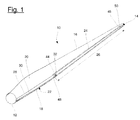
- the wind turbine rotor blade 10 off FIG. 1 has a blade root 12, a blade tip 14 on which a lightning protection receptor is disposed, a Profilendkante 16, a Profilnasenkante 18, a suction side 22 and a pressure side 20.
- An electric heater 24 extends over a longitudinal section 26 of the wind turbine rotor blade 10 in the region of the profile nose edge 18th ranging from a blade root-side end 48 of the heatable surface portion to a blade tip side end 50 of the heatable surface portion.
- the electric heater 24 is connected along its longitudinal edges to a supply line 30 arranged on the suction side and to a supply line 28 arranged on the pressure side. About the supply lines 28, 30, the supply of electrical energy.
- a temperature sensor 32 is arranged in a blade root near section 44 of the wind turbine rotor blade.
- the blade root near section 44 is located in the heated by the electric heater 24 surface area.
- the temperature sensor 32 may be connected to a controller of a wind turbine, not shown, with which the power supply to the electric heater 24 is controlled via the supply lines 28,30.
- the electric heater 24 is configured such that, during operation of the heater in the blade root near section 44 of the wind turbine rotor blade in which the temperature sensor 32 is disposed, a temperature equal to or greater than the temperature in the blade tip near section 45 is achieved.
- the blade-near section 45 is located in the heated by the electric heater 24 surface area.
- FIG. 2 shows more details of the electric heater 24.
- Well visible are the two supply lines 28, 30, which extend substantially along the longitudinal direction of the wind turbine rotor blade 10.
- a plurality of heating conductors 34 to 42 are each connected at one end to the supply line 28 and at the other end to the supply line 30.
- Each of the heating conductors 34 to 42 forms a heating element that in the FIG. 2 surrounded by a box and is responsible for the heating of just this part of the surface area.
- Each of the heating conductors 34 to 42 connects the two supply lines 28, 30 at a specific radius position.
- the flow of current takes place substantially transversely to the longitudinal direction of the wind turbine rotor blade 10.
- Each of the heating conductors 34 to 42 is arranged serpentine or meandering within the surface area heated by it, wherein the area power in the illustrated embodiment takes place by varying a "wavelength".
- the heating conductor 34 disposed closest to the blade tip 14 has a uniform wavelength in the surface area heated by it and accordingly provides a substantially uniform area performance.
- the wavelength is relatively small over the entire area covered by the heating conductor 34, so that a relatively large area performance is achieved near the blade tip 14 as needed.
- the heating conductors 36 to 40 arranged in the direction of the blade root 12 in the further course of the electric heating device 24 have a higher surface density in the region of the profile nose edge 18 than in the regions adjacent thereto laterally. This is achieved by a smaller "wavelength" in the region of the profile nose edge 18.
- the closest to the leaf root 12 (in Fig. 2 not shown) arranged heating conductor 42 has in a blade root near section 44 a particularly high surface density, which is achieved by a in this area again reduced "wavelength".
- the areal density of the heating conductor 42 is higher than the areal density of the other heating conductors in the adjacent sections.
- the area density in the blade root near section 44 is even higher than in the blade tip near section 45 which is covered by the heating conductor 34.
- the temperature sensor 32 is disposed in the blade root proximal portion 44 so as to detect the maximum temperature reached there.
- the second embodiment of the FIG. 3 differs from the first embodiment of FIG. 2 only in terms of the formation of the nearest to the blade root 12 arranged heating conductor 42.
- the blade root near section 44 in which an equal to or higher temperature is reached than in all other sections of the heated area, especially as in the blade tip near section 45, is in this Embodiment formed by a there spiral arrangement of a portion of the heat conductor 42 and a consequence of this arrangement, high surface density.
- the heatable surface area extends over at least 25% of the total length of the wind turbine rotor blade 10 and corresponds to that surface area of the wind turbine rotor blade 10, which is to be kept free of ice by the electric heater 24. It has a multiplicity of heating conductors 34 to 42, in which the areal density of the individual heating conductors 34 to 42 is chosen so as to achieve a demand-based area performance. It corresponds, for example, the closest to the Blade tip 14 arranged heating element 34 that of the first embodiment of the FIG. 2 ,
- a further heating conductor 46 which is not intended to heat the surface of the rotor blade, but to generate a reference temperature.
- This heating conductor 46 is similar to the second embodiment of FIG. 3 arranged spirally in a blade root near section 44, so that it has a particularly high surface density and achieves a correspondingly high area performance.
- the area performance in the blade root near section 44 is also selected here so that there during operation of the heater sets a temperature that is equal to or higher than the temperature in the heated surface area, in particular in the blade tip near section 45.
- the leaf temperature can be measured with a temperature sensor not shown.
Priority Applications (4)
| Application Number | Priority Date | Filing Date | Title |
|---|---|---|---|
| EP15174156.8A EP3109466B1 (fr) | 2015-06-26 | 2015-06-26 | Pale de rotor d'éolienne dotée d'un dispositif de chauffage électrique |
| DK15174156.8T DK3109466T3 (da) | 2015-06-26 | 2015-06-26 | Vindturbinerotorblad med elektrisk opvarmingsindretning |
| ES15174156T ES2703929T3 (es) | 2015-06-26 | 2015-06-26 | Pala de rotor de turbina eólica con una instalación de calefacción eléctrica |
| CA2933945A CA2933945C (fr) | 2015-06-26 | 2016-06-23 | Pale de rotor d'eolienne dotee d'un appareil de chauffage electrique |
Applications Claiming Priority (1)
| Application Number | Priority Date | Filing Date | Title |
|---|---|---|---|
| EP15174156.8A EP3109466B1 (fr) | 2015-06-26 | 2015-06-26 | Pale de rotor d'éolienne dotée d'un dispositif de chauffage électrique |
Publications (2)
| Publication Number | Publication Date |
|---|---|
| EP3109466A1 true EP3109466A1 (fr) | 2016-12-28 |
| EP3109466B1 EP3109466B1 (fr) | 2018-10-17 |
Family
ID=53496499
Family Applications (1)
| Application Number | Title | Priority Date | Filing Date |
|---|---|---|---|
| EP15174156.8A Active EP3109466B1 (fr) | 2015-06-26 | 2015-06-26 | Pale de rotor d'éolienne dotée d'un dispositif de chauffage électrique |
Country Status (4)
| Country | Link |
|---|---|
| EP (1) | EP3109466B1 (fr) |
| CA (1) | CA2933945C (fr) |
| DK (1) | DK3109466T3 (fr) |
| ES (1) | ES2703929T3 (fr) |
Cited By (2)
| Publication number | Priority date | Publication date | Assignee | Title |
|---|---|---|---|---|
| EP3604795A1 (fr) * | 2018-08-02 | 2020-02-05 | Nordex Energy GmbH | Élément chauffant et lame de rotor d'une éolienne |
| CN117601407A (zh) * | 2024-01-22 | 2024-02-27 | 东北电力大学 | 一种水平轴风力机退役叶片二次成型设备及设计方法 |
Citations (8)
| Publication number | Priority date | Publication date | Assignee | Title |
|---|---|---|---|---|
| CN101886617B (zh) * | 2010-06-07 | 2012-05-30 | 三一电气有限责任公司 | 一种风力发电机组及其叶片除冰系统 |
| WO2012164167A1 (fr) | 2011-05-31 | 2012-12-06 | Teknologian Tutkimuskeskus Vtt | Pale d'éolienne et procédé de fabrication afférent |
| EP2615302A1 (fr) * | 2012-01-10 | 2013-07-17 | Nordex Energy GmbH | Procédé de fonctionnement d'une éolienne dans lequel un danger de givre est détecté en raison de données météorologiques, et éolienne destinée à la réalisation du procédé |
| CN103161689B (zh) * | 2013-03-15 | 2014-01-22 | 湖南大学 | 一种大型风力发电组合叶片防冰与除冰系统 |
| WO2014023734A1 (fr) | 2012-08-06 | 2014-02-13 | Wobben Properties Gmbh | Chauffage de pale par résistance cfk |
| EP2738383A1 (fr) | 2012-11-30 | 2014-06-04 | Nordex Energy GmbH | Pale de rotor d'éolienne dotée d'un élément chauffant électrique |
| EP2826993A1 (fr) * | 2013-07-17 | 2015-01-21 | Spitzner Engineers GmbH | Procédé de dégivrage des pales de rotor d'une installation éolienne et système de dégivrage des pales de rotor d'une installation éolienne |
| EP2843228A1 (fr) | 2013-08-29 | 2015-03-04 | Nordex Energy GmbH | Pale de rotor d'éolienne dotée d'un élément chauffant électrique |
-
2015
- 2015-06-26 DK DK15174156.8T patent/DK3109466T3/da active
- 2015-06-26 ES ES15174156T patent/ES2703929T3/es active Active
- 2015-06-26 EP EP15174156.8A patent/EP3109466B1/fr active Active
-
2016
- 2016-06-23 CA CA2933945A patent/CA2933945C/fr active Active
Patent Citations (8)
| Publication number | Priority date | Publication date | Assignee | Title |
|---|---|---|---|---|
| CN101886617B (zh) * | 2010-06-07 | 2012-05-30 | 三一电气有限责任公司 | 一种风力发电机组及其叶片除冰系统 |
| WO2012164167A1 (fr) | 2011-05-31 | 2012-12-06 | Teknologian Tutkimuskeskus Vtt | Pale d'éolienne et procédé de fabrication afférent |
| EP2615302A1 (fr) * | 2012-01-10 | 2013-07-17 | Nordex Energy GmbH | Procédé de fonctionnement d'une éolienne dans lequel un danger de givre est détecté en raison de données météorologiques, et éolienne destinée à la réalisation du procédé |
| WO2014023734A1 (fr) | 2012-08-06 | 2014-02-13 | Wobben Properties Gmbh | Chauffage de pale par résistance cfk |
| EP2738383A1 (fr) | 2012-11-30 | 2014-06-04 | Nordex Energy GmbH | Pale de rotor d'éolienne dotée d'un élément chauffant électrique |
| CN103161689B (zh) * | 2013-03-15 | 2014-01-22 | 湖南大学 | 一种大型风力发电组合叶片防冰与除冰系统 |
| EP2826993A1 (fr) * | 2013-07-17 | 2015-01-21 | Spitzner Engineers GmbH | Procédé de dégivrage des pales de rotor d'une installation éolienne et système de dégivrage des pales de rotor d'une installation éolienne |
| EP2843228A1 (fr) | 2013-08-29 | 2015-03-04 | Nordex Energy GmbH | Pale de rotor d'éolienne dotée d'un élément chauffant électrique |
Cited By (3)
| Publication number | Priority date | Publication date | Assignee | Title |
|---|---|---|---|---|
| EP3604795A1 (fr) * | 2018-08-02 | 2020-02-05 | Nordex Energy GmbH | Élément chauffant et lame de rotor d'une éolienne |
| CN117601407A (zh) * | 2024-01-22 | 2024-02-27 | 东北电力大学 | 一种水平轴风力机退役叶片二次成型设备及设计方法 |
| CN117601407B (zh) * | 2024-01-22 | 2024-04-02 | 东北电力大学 | 一种水平轴风力机退役叶片二次成型设备及设计方法 |
Also Published As
| Publication number | Publication date |
|---|---|
| CA2933945A1 (fr) | 2016-12-26 |
| EP3109466B1 (fr) | 2018-10-17 |
| DK3109466T3 (da) | 2019-02-04 |
| ES2703929T3 (es) | 2019-03-13 |
| CA2933945C (fr) | 2023-09-26 |
Similar Documents
| Publication | Publication Date | Title |
|---|---|---|
| EP2880308B1 (fr) | Chauffage de pale par résistance prfc | |
| EP3165761B1 (fr) | Pale de rotor d'éolienne dotée d'un dispositif de chauffage electrique | |
| EP2843228B1 (fr) | Pale de rotor d'éolienne dotée d'un élément chauffant électrique | |
| DE102010051297B4 (de) | Rotorblatt einer Windenergieanlage | |
| EP2044968B1 (fr) | Evaporateur de liquide | |
| EP2812581B1 (fr) | Pompe avec chauffage intégré | |
| EP3329120B1 (fr) | Pale d'éolienne | |
| EP2738383B1 (fr) | Pale de rotor d'éolienne dotée d'un élément chauffant électrique | |
| EP2895747A1 (fr) | Bague murale de ventilateur équipée d'un élément chauffant | |
| DE102017110797A1 (de) | Windenergieanlagen-Rotorblatt | |
| EP3109465B1 (fr) | Pale de rotor d'éolienne dotée d'un dispositif de chauffage electrique | |
| DE102017116984B4 (de) | Temperiervorrichtung für eine Temperierung eines Batteriesystems sowie Batteriesystem | |
| EP3109466B1 (fr) | Pale de rotor d'éolienne dotée d'un dispositif de chauffage électrique | |
| DE102010051292B4 (de) | Rotorblatt einer Windenergieanlage | |
| EP3015707B1 (fr) | Éolienne et procédé de dégivrage d'une éolienne | |
| EP2805388B1 (fr) | Echangeur pour bague collectrice | |
| DE102017124339B4 (de) | Verstellring, Verdichter und Verfahren zum Betreiben eines Verstellrings | |
| EP3604795B1 (fr) | Élément chauffant et lame de rotor d'une éolienne | |
| EP4191053A1 (fr) | Pale de rotor pour éoliennes | |
| EP3486479A1 (fr) | Procédé de fonctionnement d'un parc éolien et parc éolien | |
| DE102015104662A1 (de) | Windenergieanlagenrotorblatt mit einer Heizeinrichtung | |
| EP4151856A1 (fr) | Pale de rotor d'éolienne | |
| DE212004000010U1 (de) | Vorrichtung zum Spinnen von Fäden bildenden Stoffen | |
| DE10258262A1 (de) | Heizvorrichtung und Verfahren zum Erwärmen eines Fadens | |
| DE19827447C1 (de) | Anordnung zur Klimatisierung von Räumen |
Legal Events
| Date | Code | Title | Description |
|---|---|---|---|
| PUAI | Public reference made under article 153(3) epc to a published international application that has entered the european phase |
Free format text: ORIGINAL CODE: 0009012 |
|
| STAA | Information on the status of an ep patent application or granted ep patent |
Free format text: STATUS: REQUEST FOR EXAMINATION WAS MADE |
|
| 17P | Request for examination filed |
Effective date: 20160511 |
|
| AK | Designated contracting states |
Kind code of ref document: A1 Designated state(s): AL AT BE BG CH CY CZ DE DK EE ES FI FR GB GR HR HU IE IS IT LI LT LU LV MC MK MT NL NO PL PT RO RS SE SI SK SM TR |
|
| AX | Request for extension of the european patent |
Extension state: BA ME |
|
| REG | Reference to a national code |
Ref country code: DE Ref legal event code: R079 Ref document number: 502015006426 Country of ref document: DE Free format text: PREVIOUS MAIN CLASS: F03D0080000000 Ipc: F03D0080400000 |
|
| GRAP | Despatch of communication of intention to grant a patent |
Free format text: ORIGINAL CODE: EPIDOSNIGR1 |
|
| STAA | Information on the status of an ep patent application or granted ep patent |
Free format text: STATUS: GRANT OF PATENT IS INTENDED |
|
| RIC1 | Information provided on ipc code assigned before grant |
Ipc: F03D 80/40 20160101AFI20180503BHEP Ipc: F03D 1/06 20060101ALI20180503BHEP |
|
| INTG | Intention to grant announced |
Effective date: 20180531 |
|
| GRAS | Grant fee paid |
Free format text: ORIGINAL CODE: EPIDOSNIGR3 |
|
| GRAA | (expected) grant |
Free format text: ORIGINAL CODE: 0009210 |
|
| STAA | Information on the status of an ep patent application or granted ep patent |
Free format text: STATUS: THE PATENT HAS BEEN GRANTED |
|
| AK | Designated contracting states |
Kind code of ref document: B1 Designated state(s): AL AT BE BG CH CY CZ DE DK EE ES FI FR GB GR HR HU IE IS IT LI LT LU LV MC MK MT NL NO PL PT RO RS SE SI SK SM TR |
|
| REG | Reference to a national code |
Ref country code: GB Ref legal event code: FG4D Free format text: NOT ENGLISH |
|
| REG | Reference to a national code |
Ref country code: CH Ref legal event code: EP |
|
| REG | Reference to a national code |
Ref country code: IE Ref legal event code: FG4D Free format text: LANGUAGE OF EP DOCUMENT: GERMAN |
|
| REG | Reference to a national code |
Ref country code: DE Ref legal event code: R096 Ref document number: 502015006426 Country of ref document: DE Ref country code: AT Ref legal event code: REF Ref document number: 1054354 Country of ref document: AT Kind code of ref document: T Effective date: 20181115 |
|
| REG | Reference to a national code |
Ref country code: DK Ref legal event code: T3 Effective date: 20190201 |
|
| REG | Reference to a national code |
Ref country code: SE Ref legal event code: TRGR |
|
| REG | Reference to a national code |
Ref country code: NL Ref legal event code: MP Effective date: 20181017 |
|
| REG | Reference to a national code |
Ref country code: LT Ref legal event code: MG4D |
|
| REG | Reference to a national code |
Ref country code: ES Ref legal event code: FG2A Ref document number: 2703929 Country of ref document: ES Kind code of ref document: T3 Effective date: 20190313 |
|
| PG25 | Lapsed in a contracting state [announced via postgrant information from national office to epo] |
Ref country code: NL Free format text: LAPSE BECAUSE OF FAILURE TO SUBMIT A TRANSLATION OF THE DESCRIPTION OR TO PAY THE FEE WITHIN THE PRESCRIBED TIME-LIMIT Effective date: 20181017 |
|
| PG25 | Lapsed in a contracting state [announced via postgrant information from national office to epo] |
Ref country code: LV Free format text: LAPSE BECAUSE OF FAILURE TO SUBMIT A TRANSLATION OF THE DESCRIPTION OR TO PAY THE FEE WITHIN THE PRESCRIBED TIME-LIMIT Effective date: 20181017 Ref country code: LT Free format text: LAPSE BECAUSE OF FAILURE TO SUBMIT A TRANSLATION OF THE DESCRIPTION OR TO PAY THE FEE WITHIN THE PRESCRIBED TIME-LIMIT Effective date: 20181017 Ref country code: IS Free format text: LAPSE BECAUSE OF FAILURE TO SUBMIT A TRANSLATION OF THE DESCRIPTION OR TO PAY THE FEE WITHIN THE PRESCRIBED TIME-LIMIT Effective date: 20190217 Ref country code: NO Free format text: LAPSE BECAUSE OF FAILURE TO SUBMIT A TRANSLATION OF THE DESCRIPTION OR TO PAY THE FEE WITHIN THE PRESCRIBED TIME-LIMIT Effective date: 20190117 Ref country code: FI Free format text: LAPSE BECAUSE OF FAILURE TO SUBMIT A TRANSLATION OF THE DESCRIPTION OR TO PAY THE FEE WITHIN THE PRESCRIBED TIME-LIMIT Effective date: 20181017 Ref country code: BG Free format text: LAPSE BECAUSE OF FAILURE TO SUBMIT A TRANSLATION OF THE DESCRIPTION OR TO PAY THE FEE WITHIN THE PRESCRIBED TIME-LIMIT Effective date: 20190117 Ref country code: PL Free format text: LAPSE BECAUSE OF FAILURE TO SUBMIT A TRANSLATION OF THE DESCRIPTION OR TO PAY THE FEE WITHIN THE PRESCRIBED TIME-LIMIT Effective date: 20181017 Ref country code: HR Free format text: LAPSE BECAUSE OF FAILURE TO SUBMIT A TRANSLATION OF THE DESCRIPTION OR TO PAY THE FEE WITHIN THE PRESCRIBED TIME-LIMIT Effective date: 20181017 |
|
| PG25 | Lapsed in a contracting state [announced via postgrant information from national office to epo] |
Ref country code: GR Free format text: LAPSE BECAUSE OF FAILURE TO SUBMIT A TRANSLATION OF THE DESCRIPTION OR TO PAY THE FEE WITHIN THE PRESCRIBED TIME-LIMIT Effective date: 20190118 Ref country code: RS Free format text: LAPSE BECAUSE OF FAILURE TO SUBMIT A TRANSLATION OF THE DESCRIPTION OR TO PAY THE FEE WITHIN THE PRESCRIBED TIME-LIMIT Effective date: 20181017 Ref country code: PT Free format text: LAPSE BECAUSE OF FAILURE TO SUBMIT A TRANSLATION OF THE DESCRIPTION OR TO PAY THE FEE WITHIN THE PRESCRIBED TIME-LIMIT Effective date: 20190217 Ref country code: AL Free format text: LAPSE BECAUSE OF FAILURE TO SUBMIT A TRANSLATION OF THE DESCRIPTION OR TO PAY THE FEE WITHIN THE PRESCRIBED TIME-LIMIT Effective date: 20181017 |
|
| REG | Reference to a national code |
Ref country code: DE Ref legal event code: R097 Ref document number: 502015006426 Country of ref document: DE |
|
| PG25 | Lapsed in a contracting state [announced via postgrant information from national office to epo] |
Ref country code: IT Free format text: LAPSE BECAUSE OF FAILURE TO SUBMIT A TRANSLATION OF THE DESCRIPTION OR TO PAY THE FEE WITHIN THE PRESCRIBED TIME-LIMIT Effective date: 20181017 Ref country code: CZ Free format text: LAPSE BECAUSE OF FAILURE TO SUBMIT A TRANSLATION OF THE DESCRIPTION OR TO PAY THE FEE WITHIN THE PRESCRIBED TIME-LIMIT Effective date: 20181017 |
|
| PLBE | No opposition filed within time limit |
Free format text: ORIGINAL CODE: 0009261 |
|
| STAA | Information on the status of an ep patent application or granted ep patent |
Free format text: STATUS: NO OPPOSITION FILED WITHIN TIME LIMIT |
|
| PG25 | Lapsed in a contracting state [announced via postgrant information from national office to epo] |
Ref country code: RO Free format text: LAPSE BECAUSE OF FAILURE TO SUBMIT A TRANSLATION OF THE DESCRIPTION OR TO PAY THE FEE WITHIN THE PRESCRIBED TIME-LIMIT Effective date: 20181017 Ref country code: EE Free format text: LAPSE BECAUSE OF FAILURE TO SUBMIT A TRANSLATION OF THE DESCRIPTION OR TO PAY THE FEE WITHIN THE PRESCRIBED TIME-LIMIT Effective date: 20181017 Ref country code: SM Free format text: LAPSE BECAUSE OF FAILURE TO SUBMIT A TRANSLATION OF THE DESCRIPTION OR TO PAY THE FEE WITHIN THE PRESCRIBED TIME-LIMIT Effective date: 20181017 Ref country code: SK Free format text: LAPSE BECAUSE OF FAILURE TO SUBMIT A TRANSLATION OF THE DESCRIPTION OR TO PAY THE FEE WITHIN THE PRESCRIBED TIME-LIMIT Effective date: 20181017 |
|
| 26N | No opposition filed |
Effective date: 20190718 |
|
| PG25 | Lapsed in a contracting state [announced via postgrant information from national office to epo] |
Ref country code: SI Free format text: LAPSE BECAUSE OF FAILURE TO SUBMIT A TRANSLATION OF THE DESCRIPTION OR TO PAY THE FEE WITHIN THE PRESCRIBED TIME-LIMIT Effective date: 20181017 |
|
| PG25 | Lapsed in a contracting state [announced via postgrant information from national office to epo] |
Ref country code: MC Free format text: LAPSE BECAUSE OF FAILURE TO SUBMIT A TRANSLATION OF THE DESCRIPTION OR TO PAY THE FEE WITHIN THE PRESCRIBED TIME-LIMIT Effective date: 20181017 |
|
| REG | Reference to a national code |
Ref country code: CH Ref legal event code: PL |
|
| GBPC | Gb: european patent ceased through non-payment of renewal fee |
Effective date: 20190626 |
|
| REG | Reference to a national code |
Ref country code: BE Ref legal event code: MM Effective date: 20190630 |
|
| PG25 | Lapsed in a contracting state [announced via postgrant information from national office to epo] |
Ref country code: TR Free format text: LAPSE BECAUSE OF FAILURE TO SUBMIT A TRANSLATION OF THE DESCRIPTION OR TO PAY THE FEE WITHIN THE PRESCRIBED TIME-LIMIT Effective date: 20181017 |
|
| PG25 | Lapsed in a contracting state [announced via postgrant information from national office to epo] |
Ref country code: GB Free format text: LAPSE BECAUSE OF NON-PAYMENT OF DUE FEES Effective date: 20190626 Ref country code: IE Free format text: LAPSE BECAUSE OF NON-PAYMENT OF DUE FEES Effective date: 20190626 |
|
| PG25 | Lapsed in a contracting state [announced via postgrant information from national office to epo] |
Ref country code: CH Free format text: LAPSE BECAUSE OF NON-PAYMENT OF DUE FEES Effective date: 20190630 Ref country code: BE Free format text: LAPSE BECAUSE OF NON-PAYMENT OF DUE FEES Effective date: 20190630 Ref country code: LI Free format text: LAPSE BECAUSE OF NON-PAYMENT OF DUE FEES Effective date: 20190630 Ref country code: LU Free format text: LAPSE BECAUSE OF NON-PAYMENT OF DUE FEES Effective date: 20190626 |
|
| PG25 | Lapsed in a contracting state [announced via postgrant information from national office to epo] |
Ref country code: FR Free format text: LAPSE BECAUSE OF NON-PAYMENT OF DUE FEES Effective date: 20190630 |
|
| REG | Reference to a national code |
Ref country code: DE Ref legal event code: R082 Ref document number: 502015006426 Country of ref document: DE Representative=s name: HAUCK PATENTANWALTSPARTNERSCHAFT MBB, DE Ref country code: DE Ref legal event code: R081 Ref document number: 502015006426 Country of ref document: DE Owner name: NORDEX ENERGY SE & CO. KG, DE Free format text: FORMER OWNER: NORDEX ENERGY GMBH, 22419 HAMBURG, DE |
|
| PG25 | Lapsed in a contracting state [announced via postgrant information from national office to epo] |
Ref country code: CY Free format text: LAPSE BECAUSE OF FAILURE TO SUBMIT A TRANSLATION OF THE DESCRIPTION OR TO PAY THE FEE WITHIN THE PRESCRIBED TIME-LIMIT Effective date: 20181017 |
|
| PG25 | Lapsed in a contracting state [announced via postgrant information from national office to epo] |
Ref country code: MT Free format text: LAPSE BECAUSE OF FAILURE TO SUBMIT A TRANSLATION OF THE DESCRIPTION OR TO PAY THE FEE WITHIN THE PRESCRIBED TIME-LIMIT Effective date: 20181017 Ref country code: HU Free format text: LAPSE BECAUSE OF FAILURE TO SUBMIT A TRANSLATION OF THE DESCRIPTION OR TO PAY THE FEE WITHIN THE PRESCRIBED TIME-LIMIT; INVALID AB INITIO Effective date: 20150626 |
|
| REG | Reference to a national code |
Ref country code: AT Ref legal event code: MM01 Ref document number: 1054354 Country of ref document: AT Kind code of ref document: T Effective date: 20200626 |
|
| PG25 | Lapsed in a contracting state [announced via postgrant information from national office to epo] |
Ref country code: AT Free format text: LAPSE BECAUSE OF NON-PAYMENT OF DUE FEES Effective date: 20200626 |
|
| PG25 | Lapsed in a contracting state [announced via postgrant information from national office to epo] |
Ref country code: MK Free format text: LAPSE BECAUSE OF FAILURE TO SUBMIT A TRANSLATION OF THE DESCRIPTION OR TO PAY THE FEE WITHIN THE PRESCRIBED TIME-LIMIT Effective date: 20181017 |
|
| P01 | Opt-out of the competence of the unified patent court (upc) registered |
Effective date: 20230602 |
|
| PGFP | Annual fee paid to national office [announced via postgrant information from national office to epo] |
Ref country code: DK Payment date: 20230621 Year of fee payment: 9 Ref country code: DE Payment date: 20230620 Year of fee payment: 9 |
|
| PGFP | Annual fee paid to national office [announced via postgrant information from national office to epo] |
Ref country code: SE Payment date: 20230622 Year of fee payment: 9 |
|
| PGFP | Annual fee paid to national office [announced via postgrant information from national office to epo] |
Ref country code: ES Payment date: 20230719 Year of fee payment: 9 |