EP3109462A1 - Airflow generator power supply and wind turbine generator - Google Patents
Airflow generator power supply and wind turbine generator Download PDFInfo
- Publication number
- EP3109462A1 EP3109462A1 EP16168778.5A EP16168778A EP3109462A1 EP 3109462 A1 EP3109462 A1 EP 3109462A1 EP 16168778 A EP16168778 A EP 16168778A EP 3109462 A1 EP3109462 A1 EP 3109462A1
- Authority
- EP
- European Patent Office
- Prior art keywords
- alternating
- current voltage
- transformers
- frequency converter
- airflow
- Prior art date
- Legal status (The legal status is an assumption and is not a legal conclusion. Google has not performed a legal analysis and makes no representation as to the accuracy of the status listed.)
- Granted
Links
- 238000010586 diagram Methods 0.000 description 21
- 238000010248 power generation Methods 0.000 description 4
- 230000007423 decrease Effects 0.000 description 3
- 230000006866 deterioration Effects 0.000 description 2
- 239000003989 dielectric material Substances 0.000 description 2
- 238000009434 installation Methods 0.000 description 2
- 238000000034 method Methods 0.000 description 2
- 230000003247 decreasing effect Effects 0.000 description 1
- 230000005669 field effect Effects 0.000 description 1
- 230000006698 induction Effects 0.000 description 1
- 230000001939 inductive effect Effects 0.000 description 1
- 238000012986 modification Methods 0.000 description 1
- 230000004048 modification Effects 0.000 description 1
- 239000007787 solid Substances 0.000 description 1
- 238000006467 substitution reaction Methods 0.000 description 1
Images




Classifications
-
- H—ELECTRICITY
- H02—GENERATION; CONVERSION OR DISTRIBUTION OF ELECTRIC POWER
- H02M—APPARATUS FOR CONVERSION BETWEEN AC AND AC, BETWEEN AC AND DC, OR BETWEEN DC AND DC, AND FOR USE WITH MAINS OR SIMILAR POWER SUPPLY SYSTEMS; CONVERSION OF DC OR AC INPUT POWER INTO SURGE OUTPUT POWER; CONTROL OR REGULATION THEREOF
- H02M5/00—Conversion of AC power input into AC power output, e.g. for change of voltage, for change of frequency, for change of number of phases
- H02M5/02—Conversion of AC power input into AC power output, e.g. for change of voltage, for change of frequency, for change of number of phases without intermediate conversion into DC
- H02M5/04—Conversion of AC power input into AC power output, e.g. for change of voltage, for change of frequency, for change of number of phases without intermediate conversion into DC by static converters
- H02M5/10—Conversion of AC power input into AC power output, e.g. for change of voltage, for change of frequency, for change of number of phases without intermediate conversion into DC by static converters using transformers
- H02M5/12—Conversion of AC power input into AC power output, e.g. for change of voltage, for change of frequency, for change of number of phases without intermediate conversion into DC by static converters using transformers for conversion of voltage or current amplitude only
-
- F—MECHANICAL ENGINEERING; LIGHTING; HEATING; WEAPONS; BLASTING
- F03—MACHINES OR ENGINES FOR LIQUIDS; WIND, SPRING, OR WEIGHT MOTORS; PRODUCING MECHANICAL POWER OR A REACTIVE PROPULSIVE THRUST, NOT OTHERWISE PROVIDED FOR
- F03D—WIND MOTORS
- F03D9/00—Adaptations of wind motors for special use; Combinations of wind motors with apparatus driven thereby; Wind motors specially adapted for installation in particular locations
- F03D9/20—Wind motors characterised by the driven apparatus
- F03D9/25—Wind motors characterised by the driven apparatus the apparatus being an electrical generator
-
- F—MECHANICAL ENGINEERING; LIGHTING; HEATING; WEAPONS; BLASTING
- F03—MACHINES OR ENGINES FOR LIQUIDS; WIND, SPRING, OR WEIGHT MOTORS; PRODUCING MECHANICAL POWER OR A REACTIVE PROPULSIVE THRUST, NOT OTHERWISE PROVIDED FOR
- F03D—WIND MOTORS
- F03D1/00—Wind motors with rotation axis substantially parallel to the air flow entering the rotor
- F03D1/06—Rotors
- F03D1/065—Rotors characterised by their construction elements
- F03D1/0675—Rotors characterised by their construction elements of the blades
-
- F—MECHANICAL ENGINEERING; LIGHTING; HEATING; WEAPONS; BLASTING
- F03—MACHINES OR ENGINES FOR LIQUIDS; WIND, SPRING, OR WEIGHT MOTORS; PRODUCING MECHANICAL POWER OR A REACTIVE PROPULSIVE THRUST, NOT OTHERWISE PROVIDED FOR
- F03D—WIND MOTORS
- F03D7/00—Controlling wind motors
- F03D7/02—Controlling wind motors the wind motors having rotation axis substantially parallel to the air flow entering the rotor
- F03D7/022—Adjusting aerodynamic properties of the blades
-
- F—MECHANICAL ENGINEERING; LIGHTING; HEATING; WEAPONS; BLASTING
- F03—MACHINES OR ENGINES FOR LIQUIDS; WIND, SPRING, OR WEIGHT MOTORS; PRODUCING MECHANICAL POWER OR A REACTIVE PROPULSIVE THRUST, NOT OTHERWISE PROVIDED FOR
- F03D—WIND MOTORS
- F03D7/00—Controlling wind motors
- F03D7/02—Controlling wind motors the wind motors having rotation axis substantially parallel to the air flow entering the rotor
- F03D7/028—Controlling wind motors the wind motors having rotation axis substantially parallel to the air flow entering the rotor controlling wind motor output power
-
- F—MECHANICAL ENGINEERING; LIGHTING; HEATING; WEAPONS; BLASTING
- F03—MACHINES OR ENGINES FOR LIQUIDS; WIND, SPRING, OR WEIGHT MOTORS; PRODUCING MECHANICAL POWER OR A REACTIVE PROPULSIVE THRUST, NOT OTHERWISE PROVIDED FOR
- F03D—WIND MOTORS
- F03D7/00—Controlling wind motors
- F03D7/02—Controlling wind motors the wind motors having rotation axis substantially parallel to the air flow entering the rotor
- F03D7/0296—Controlling wind motors the wind motors having rotation axis substantially parallel to the air flow entering the rotor to prevent, counteract or reduce noise emissions
-
- H—ELECTRICITY
- H02—GENERATION; CONVERSION OR DISTRIBUTION OF ELECTRIC POWER
- H02K—DYNAMO-ELECTRIC MACHINES
- H02K11/00—Structural association of dynamo-electric machines with electric components or with devices for shielding, monitoring or protection
- H02K11/0094—Structural association with other electrical or electronic devices
-
- H—ELECTRICITY
- H02—GENERATION; CONVERSION OR DISTRIBUTION OF ELECTRIC POWER
- H02K—DYNAMO-ELECTRIC MACHINES
- H02K7/00—Arrangements for handling mechanical energy structurally associated with dynamo-electric machines, e.g. structural association with mechanical driving motors or auxiliary dynamo-electric machines
- H02K7/18—Structural association of electric generators with mechanical driving motors, e.g. with turbines
- H02K7/1807—Rotary generators
- H02K7/1823—Rotary generators structurally associated with turbines or similar engines
- H02K7/183—Rotary generators structurally associated with turbines or similar engines wherein the turbine is a wind turbine
-
- H—ELECTRICITY
- H02—GENERATION; CONVERSION OR DISTRIBUTION OF ELECTRIC POWER
- H02M—APPARATUS FOR CONVERSION BETWEEN AC AND AC, BETWEEN AC AND DC, OR BETWEEN DC AND DC, AND FOR USE WITH MAINS OR SIMILAR POWER SUPPLY SYSTEMS; CONVERSION OF DC OR AC INPUT POWER INTO SURGE OUTPUT POWER; CONTROL OR REGULATION THEREOF
- H02M5/00—Conversion of AC power input into AC power output, e.g. for change of voltage, for change of frequency, for change of number of phases
- H02M5/40—Conversion of AC power input into AC power output, e.g. for change of voltage, for change of frequency, for change of number of phases with intermediate conversion into DC
- H02M5/42—Conversion of AC power input into AC power output, e.g. for change of voltage, for change of frequency, for change of number of phases with intermediate conversion into DC by static converters
- H02M5/44—Conversion of AC power input into AC power output, e.g. for change of voltage, for change of frequency, for change of number of phases with intermediate conversion into DC by static converters using discharge tubes or semiconductor devices to convert the intermediate DC into AC
-
- F—MECHANICAL ENGINEERING; LIGHTING; HEATING; WEAPONS; BLASTING
- F05—INDEXING SCHEMES RELATING TO ENGINES OR PUMPS IN VARIOUS SUBCLASSES OF CLASSES F01-F04
- F05B—INDEXING SCHEME RELATING TO WIND, SPRING, WEIGHT, INERTIA OR LIKE MOTORS, TO MACHINES OR ENGINES FOR LIQUIDS COVERED BY SUBCLASSES F03B, F03D AND F03G
- F05B2220/00—Application
- F05B2220/70—Application in combination with
- F05B2220/706—Application in combination with an electrical generator
- F05B2220/7064—Application in combination with an electrical generator of the alternating current (A.C.) type
-
- F—MECHANICAL ENGINEERING; LIGHTING; HEATING; WEAPONS; BLASTING
- F05—INDEXING SCHEMES RELATING TO ENGINES OR PUMPS IN VARIOUS SUBCLASSES OF CLASSES F01-F04
- F05B—INDEXING SCHEME RELATING TO WIND, SPRING, WEIGHT, INERTIA OR LIKE MOTORS, TO MACHINES OR ENGINES FOR LIQUIDS COVERED BY SUBCLASSES F03B, F03D AND F03G
- F05B2240/00—Components
- F05B2240/20—Rotors
- F05B2240/30—Characteristics of rotor blades, i.e. of any element transforming dynamic fluid energy to or from rotational energy and being attached to a rotor
-
- F—MECHANICAL ENGINEERING; LIGHTING; HEATING; WEAPONS; BLASTING
- F05—INDEXING SCHEMES RELATING TO ENGINES OR PUMPS IN VARIOUS SUBCLASSES OF CLASSES F01-F04
- F05B—INDEXING SCHEME RELATING TO WIND, SPRING, WEIGHT, INERTIA OR LIKE MOTORS, TO MACHINES OR ENGINES FOR LIQUIDS COVERED BY SUBCLASSES F03B, F03D AND F03G
- F05B2260/00—Function
- F05B2260/96—Preventing, counteracting or reducing vibration or noise
-
- F—MECHANICAL ENGINEERING; LIGHTING; HEATING; WEAPONS; BLASTING
- F05—INDEXING SCHEMES RELATING TO ENGINES OR PUMPS IN VARIOUS SUBCLASSES OF CLASSES F01-F04
- F05B—INDEXING SCHEME RELATING TO WIND, SPRING, WEIGHT, INERTIA OR LIKE MOTORS, TO MACHINES OR ENGINES FOR LIQUIDS COVERED BY SUBCLASSES F03B, F03D AND F03G
- F05B2270/00—Control
- F05B2270/10—Purpose of the control system
- F05B2270/103—Purpose of the control system to affect the output of the engine
- F05B2270/1033—Power (if explicitly mentioned)
-
- Y—GENERAL TAGGING OF NEW TECHNOLOGICAL DEVELOPMENTS; GENERAL TAGGING OF CROSS-SECTIONAL TECHNOLOGIES SPANNING OVER SEVERAL SECTIONS OF THE IPC; TECHNICAL SUBJECTS COVERED BY FORMER USPC CROSS-REFERENCE ART COLLECTIONS [XRACs] AND DIGESTS
- Y02—TECHNOLOGIES OR APPLICATIONS FOR MITIGATION OR ADAPTATION AGAINST CLIMATE CHANGE
- Y02E—REDUCTION OF GREENHOUSE GAS [GHG] EMISSIONS, RELATED TO ENERGY GENERATION, TRANSMISSION OR DISTRIBUTION
- Y02E10/00—Energy generation through renewable energy sources
- Y02E10/70—Wind energy
- Y02E10/72—Wind turbines with rotation axis in wind direction
-
- Y—GENERAL TAGGING OF NEW TECHNOLOGICAL DEVELOPMENTS; GENERAL TAGGING OF CROSS-SECTIONAL TECHNOLOGIES SPANNING OVER SEVERAL SECTIONS OF THE IPC; TECHNICAL SUBJECTS COVERED BY FORMER USPC CROSS-REFERENCE ART COLLECTIONS [XRACs] AND DIGESTS
- Y02—TECHNOLOGIES OR APPLICATIONS FOR MITIGATION OR ADAPTATION AGAINST CLIMATE CHANGE
- Y02E—REDUCTION OF GREENHOUSE GAS [GHG] EMISSIONS, RELATED TO ENERGY GENERATION, TRANSMISSION OR DISTRIBUTION
- Y02E10/00—Energy generation through renewable energy sources
- Y02E10/70—Wind energy
- Y02E10/76—Power conversion electric or electronic aspects
Definitions
- Embodiments described herein relate generally to an airflow generator power supply and wind turbine generator.
- a power generation efficiency sometimes deteriorates due to change of a wind power or a wind direction. Further, in the wind turbine generator, noise sometimes occurs at a time of generation.
- the wind turbine generator having airflow generator on its blades is studied to suppress such deterioration of the power generation efficiency and occurrence of noise.
- the airflow generator has a pair of electrodes sandwiching a dielectric, and generates a plasma airflow by applying alternating-current voltage to the pair of electrodes. The plasma airflow suppresses deterioration of the power generation efficiency and occurrence of noise in the wind turbine generator.
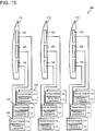
- Fig. 13 shows a conventional wind turbine generator.
- the wind turbine generator 100 has a plurality of airflow generators 120 on blades 110. Normally, the wind turbine generator 100 has airflow generator power supplies 130, each airflow generator power supply 130 corresponds to a different airflow generator 120.
- the airflow generator power supply 130 has a frequency converter 131 and a transformer 132.
- the frequency converter 131 converts a frequency of alternating-current voltage inputted from a not-shown external power supply into a frequency optimal for the airflow generator 120.
- the transformer 132 converts a voltage value of alternating-current voltage inputted from the frequency converter 131 into a voltage value optimal for the airflow generator 120.
- Enlarging the blade 110 can improve a power generation efficiency of the wind turbine generator 100. However, enlargement of the blade 110 will increase the number of the airflow generators 120, resulting in increasing the number of the airflow generator power supplies 130.
- the wind turbine generator 100 is demanded to miniaturize the airflow generator power supply 130, since an installation location and an installation area of the airflow generator power supply 130 are limited.
- a problem the present invention intends to solve is to provide an airflow generator power supply which is easy to be miniaturized.
- An airflow generator power supply of an embodiment supplies alternating-current voltage to a plurality of airflow generators on a blade of a wind turbine generator.
- the airflow generator power supply of the embodiment has a frequency converter, a plurality of transformers, and a switch.
- the frequency converter generates alternating-current voltage.
- Each transformer amplifies the alternating-current voltage and applies the amplified voltage to the corresponding airflow generator.
- the switch outputs the alternating-current voltage from the frequency converter to one selected from the transformers.
- an airflow generator power supply which is easy to be miniaturized can be provided.
- Fig. 1 is a perspective view showing a wind turbine generator.
- Fig. 2 is a cross-sectional view showing an airflow generator.
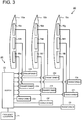
- Fig. 3 is a diagram showing an airflow generator power supply.
- Fig. 4 is a diagram showing a frequency converter.
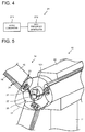
- Fig. 5 is a diagram showing a method for mounting the airflow generator power supply.
- Fig. 6 is a diagram showing a timing chart of a switch.
- Fig. 7 is a diagram showing a state of alternating-current voltage applied to the airflow generator.
- the wind turbine generator 10 has a tower 11 installed on the ground.
- a nacelle 12 housing a generator is disposed in a top portion of the tower 11.
- An aerovane 13 for measuring a wind direction or a speed of wind is disposed in an upper portion of the nacelle 12.
- a rotor 14 is provided on a windward side of the nacelle 12.
- the rotor 14 has three blades 15.
- the blades 15 are supported by a rotary shaft 121 ( Fig. 5 ) of the generator, the rotary shaft 121 projects from the nacelle 12.
- Three airflow generators 16 are provided in a front edge of the blades 15, from a blade tip to a blade root.
- the airflow generator 16 has a first electrode 161, a second electrode 162 disposed apart from the first electrode 161, and a dielectric 163 at least disposed therebetween.
- a dielectric material of the dielectric 163 is properly selected from known dielectric materials in a solid state in compliance with usage environment or the like.
- the airflow generator 16 generates a plasma airflow flowing from a first electrode 161 side to a second electrode 162 side by applying alternating-current voltage to the first electrode 161 and the second electrode 162.
- an airflow generator power supply 20 has a frequency converter 21, a switch 22, and a transformer 23.
- One frequency converter 21 is provided in the wind turbine generator 10.
- the frequency converter 21 outputs alternating-current voltage having a frequency higher than the frequency of alternating-current voltage inputted from the external power supply.
- the waveform of the alternating-current voltage outputted from the frequency converter 21 can be a pulsed waveform such as of positive polarity, of negative polarity, and bipolar of positive and negative polarities, a sinusoidal waveform, or an intermittent sinusoidal waveform, and the waveform is not limited in particular.
- the frequency converter 21 can change a frequency of alternating-current voltage to output at any time.
- the frequency converter 21 converts the inputted alternating-current voltage into alternating-current voltage of a higher frequency.
- the frequency converter 21 has an AC/DC convertor 211 and a high frequency generator 212 (inverter), for example.
- the AC/DC convertor 211 converts alternating-current voltage (AC) into direct-current voltage (DC).
- AC alternating-current voltage
- DC direct-current voltage
- the high frequency generator 212 receives the direct-current voltage converted by the AC/DC convertor 211 and outputs alternating-current voltage having a frequency higher than the frequency of the alternating-current voltage inputted from the external power supply.
- the alternating-current voltage is generated by switching of IGBT (insulated gate bipolar transistor), an FET (field-effect transistor), or the like, for example.
- the frequency of the alternating-current voltage is normally preferable to be about 1 to 20 kHz.
- Each of the transformer 23 is provided for the corresponding airflow generator 16. More specifically, the transformers 23a, 23b, 23c are provided for the airflow generators 16a, 16b, 16c of the blade 15a. Similarly, the transformers 23d, 23e, 23f are provided for the airflow generators 16d, 16e, 16f of the blade 15b, and the transformers 23g, 23h, 23i are provided for the airflow generators 16g, 16h, 16i of the blade 15c.
- the transformer 23 receives the alternating-current voltage generated by the frequency converter 21, and outputs alternating-current voltage having a voltage value higher than the inputted alternating-current voltage.
- the voltage value of the outputted alternating-current voltage is normally preferable to be several kV.
- the frequency converter 21 and the transformers 23 are connected via the switch 22.
- One switch 22 is provided in the wind turbine generator 10 and outputs the alternating-current voltage inputted from the frequency converter 21 to the specific transformer 23 selected from the transformers 23.
- the switch 22 has switch elements of which the number is the same as the number of the transformers 23, for example, and controls continuity between the frequency converter 21 and the individual transformers 23 separately. Such a switch 22 can adjust a time during which the alternating-current voltage is applied to the individual airflow generators 16 and a cycle at which the alternating-current voltage is applied, thus can effectively drive the individual airflow generators.
- the switch element can be controlled by a controller built in the switch 22, for example.
- the airflow generator power supply 20 is provided inside a nose cone 17, for example.
- the frequency converter 21 and the switch 22 are provided in an end of the rotary shaft 121 of the power generator, for example.
- the transformer 23 is provided in an end surface on a blade root side of the blade 15, for example.
- the blade 15 has transformers 23 of which the number is the same as the number of the airflow generators 16, for example.
- the frequency converter 21 and the switch 22 as well as the switch 22 and the transformer 23 are connected by connection induction wires 24.
- the alternating-current voltage is supplied to the frequency converter 21 from the external power supply disposed outside the wind turbine generator 10 by a not-shown connection inductive wire.
- the alternating-current voltage is transmitted between a rotation portion and a non-rotation portion (for example, between the rotary shaft 121 of the power generator and portions other than the rotary shaft 121 in the wind turbine generator 10) via a sliding-type connector such as a slip ring, for example.
- the airflow generator power supply 20 in the rotation portion such as a nose cone 17 of the wind turbine generator 10 can suppress application of alternating-current voltage with a high frequency and a high voltage to the sliding-type connector. Thereby, the alternating-current voltage is applied to the airflow generator 16 stably, and occurrence of noise is also suppressed.
- the airflow generator power supply 20 may be provided outside the nose cone 17, for example, inside or outside the blade 15. Further, the airflow generator power supply 20 is preferable to be provided in the rotation portion such as a blade 15 and a nose cone 17, but components other than the transformer 23 (that is, the frequency converter 21 and the switch 22) may be provided in other than the rotation portion.
- components other than the transformer 23 that is, the frequency converter 21 and the switch 22
- the transformer 23 is provided in the rotation portion, alternating-current voltage having a high voltage is not applied to the sliding type connector, so that the alternating-current voltage is applied to the airflow generator 16 stably and occurrence of noise is suppressed.
- Fig. 6 is a diagram showing a timing chart of the switch 22. Note that switch elements SWa to SWi are built in the switch 22, the transformer 23a being connected to the switch element SWa, the transformer 23b being connected to the switch element SWb, and similarly hereinafter, the transformers 23c to 23i being connected to the switch elements SWc to SWi.
- the switch elements SWa to SWi are made to be in ON states in this order, for example. After the switch element SWi is made to be in the ON state, the switch elements SWa to SWi are made to be in the ON states again in this order.
- the transformers 23 continued to the frequency converter 21 are switched as above, the alternating-current voltage is outputted to all the transformers 23 by one frequency converter 21. In other words, the alternating-current voltage is applied to all the airflow generators 16 by one frequency converter 21.
- Fig. 7 shows a state of the alternating-current voltage applied to the airflow generator 16.
- the alternating-current voltage is applied to the airflow generator 16 cyclically in a pulsed way.
- a ratio (duty ratio, ⁇ /T) of a pulse width ( ⁇ ) being a time during which the alternating-current voltage is actually applied to a cycle (T) at which the alternating-current voltage is applied is about 1 to 5%.
- the duty ratio is about 1 to 5%, the time during which the frequency converter 21 actually applies the alternating-current voltage to the individual airflow generators 16 is short. Under the circumstances, switching the transformers 23 continued to the frequency converter 21 can make one frequency converter 21 to output the alternating-current voltage to all the transformers 23, consequently to apply the alternating-current voltage to all the airflow generators 16.
- alternating-current voltage of an optimal frequency (F) is applied to the airflow generator 16.
- the optimal frequency (F) is obtained by a formula (1) below.
- “St” indicates a Strouhal number
- “n” indicates a rotation number (rpm)
- “Rn” indicates a representative radius
- “Cn” indicates a representative chord length.
- the representative radius (Rn) is a representative radius of the airflow generator 16.
- the representative chord length (Cn) is a chord length of the blade 15 in the representative radius (Rn).
- the frequency (F) of the alternating-current voltage changes depending on the representative radius (Rn) and the representative chord length (Cn).
- the frequency (F) of the alternating-current voltage changes depending on a position of the airflow generator 16, particularly a position in a longitudinal direction of the blade 15. Therefore, it is preferable that the frequency converter 21 alters a frequency of alternating-current voltage to output in time with switching of the switch 22, particularly switching at a time that the position (position in the longitudinal direction of the blade 15) of the airflow generator 16 being a continued object changes.
- a step of a most outside in the longitudinal direction of the blade 15a is indicated as a first step
- the airflow generator 16a of the first step, the airflow generator 16b of a second step, and the airflow generator 16c of a third step are different in position in the longitudinal direction of the blade 15. Therefore, if the alternating-current voltage is to be applied in order of the above, it is preferable to alter the frequency of the alternating-current voltage which the frequency converter 21 generates.
- the airflow generator 16d of a first step the airflow generator 16e of a second step
- the airflow generator 16f of a third step of the blade 15b in order and also in a case where the alternating-current voltage is applied to the airflow generator 16g of a first step, the airflow generator 16h of a second step, the airflow generator 16i of a third step of the blade 15c in order, it is preferable to change the frequency of the alternating-current voltage which the frequency converter 21 generates.
- the alternating-current voltage may be applied simultaneously to the airflow generators 16 whose frequencies of the alternating-current voltage are the same as described above.
- the switch elements SWa, SWd, SWg corresponding to the airflow generators 16a, 16d, 16g of the first step may be made to be in the ON state simultaneously, and thereafter, the switch elements SWb, SWe, SWh corresponding to the airflow generators 16b, 16e, 16h of the second step may be made to be in the ON states simultaneously, and further the switch elements SWc, SWf, SWi corresponding to the airflow generators 16c, 16f, 16i of the third step may be made to be in the ON state simultaneously.
- the airflow generator power supply 20 of the first embodiment since the alternating-current voltage is applied to all the airflow generators 16 by one frequency converter 21, the number of the frequency converters 21 decreases compared with a case where a frequency converter is provided for every airflow generator as in a conventional art. Thereby, the airflow generator power supply 20 is miniaturized.
- the order within the unit of repetition can be altered as necessary. Further, as the unit of repetition, two kinds or more can be adopted. Normally, within the unit of repetition, it is preferable that the switch elements SWa to SWi are made to be in the ON states at least once.
- wind turbine generator of the second embodiment is different from the wind turbine generator of the first embodiment only in configuration of airflow generator power supply, and thus only an airflow generator power supply will be described.
- Fig. 9 is a diagram showing the airflow generator power supply in the second embodiment.
- a transformer 43 is provided for every group constituted by airflow generators 16 whose positions in a longitudinal direction in blades 15 are equal.
- one transformer 43a is provided for the group of the airflow generators 16 of a first step, that is, the group constituted by the airflow generator 16a of the blade 15a, the airflow generator 16d of the blade 15b, and the airflow generator 16g of the blade 15c.
- one transformer 43b is provided for the group of the airflow generators 16 of a second step, that is, the group constituted by the airflow generator 16b of the blade 15a, the airflow generator 16e of the blade 15b, and the airflow generator 16h of the blade 15c.
- one transformer 43c is provided for the group of the airflow generators 16 of a third step, that is, the group constituted by the airflow generator 16c of the blade 15a, the airflow generator 16f of the blade 15b, and the airflow generator 16i of the blade 15c.
- the switch 42 has the same number of switch elements as the transformer 43 built-in, for example, and controls continuity between the frequency converter 41 and the individual transformers 43 separately.
- Fig. 10 is a diagram showing a timing chart of the switch 42.
- switch elements SWa to SWc are built in the switch 42, the transformer 43a being connected to the switch element SWa, the transformer 43b being connected to the switch element SWb, and the transformer 43c being connected to the switch elements SWc.
- the switch elements SWa to SWc are made to be in ON states in this order, for example. After the switch element SWc is made to be in the ON state, the switch elements SWa to SWc are made to be in the ON states again in this order. Since the transformers 43 continued to the frequency converter 41 are switched as above, the alternating-current voltage is outputted to all the transformers 43 by one frequency converter 41. In other words, the alternating-current voltage is applied to all the airflow generators 16 by one frequency converter 41.
- the airflow generator power supply 40 of the second embodiment since the transformer 43 is provided for every group constituted by the airflow generators 16 whose positions in the longitudinal direction in the blades 15 are equal, the number of the transformers 43 decreases compared with a case where the transformer is provided for every airflow generator as in a conventional art. Thereby, the airflow generator power supply 40 is miniaturized.
- the order within the unit of repetition can be altered as necessary. Further, as the unit of repetition, two kinds or more can be adopted. Normally, within the unit of repetition, it is preferable that the switch elements SWa to SWc are made to be in the ON states at least once.
- wind turbine generator of the third embodiment is different from the wind turbine generator of the first embodiment only in configuration of airflow generator power supply, and thus only an airflow generator power supply will be described.
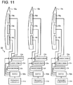
- Fig. 11 is a diagram showing the airflow generator power supply in the third embodiment.
- a transformer 53 is provided for every airflow generator 16. Further, a frequency converter 51 and a switch 52 are provided for every blade 15.
- one frequency converter 51a, one switch 52a, and three transformers 53a, 53b, 53c are provided for the blade 15a.
- one frequency converter 51b, one switch 52b, and three transformers 53d, 53e, 53f are provided for the blade 15b, and three transformers 53d, 53e, 53f are provided, and for the blade 15c, one frequency converter 51c, one switch 52c, and three transformers 53g, 53h, 53i are provided.
- the frequency converter 51, the switch 52, and the transformer 53 are not necessarily required to be disposed in the blade itself, and may be disposed in a part other than the blade.
- the frequency converter 51 and three transformers 53 are connected via the switch 52.
- the switch 52 has the same number of switch elements as the transformer 53 built-in, for example, and controls continuity between the frequency converter 51 and the individual transformers 53 separately.
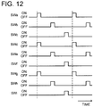
- Fig. 12 is a diagram showing a timing chart of the switch 52.
- switch elements SWa to SWc are built in the switch 52a and connected to the transformers 53a to 53c.
- the switch elements SWd to SWf are built in the switch 52b and the transformers 53d, 53e, 53f are connected thereto.
- the switch elements SWg, SWh, SWi are built in the switch 52c and the transformers 53g, 53h, 53i are connected thereto.
- the switch elements SWa to SWc are made to be in ON states in this order, for example. After the switch element SWc is made to be in the ON state, the switch elements SWa to SWc are made to be in the ON state again in this order. Similarly, the switch elements SWd to SWf are made to be in ON states in this order, for example, and the above is carried out repeatedly. The switch elements SWg to SWi are made to be in ON states in this order, for example, and the above is carried out repeatedly.
- the airflow generator power supply 50 of the third embodiment since the frequency converter 51 is provided for every blade 15, the number of the frequency converters 51 decreases compared with a case where a frequency converter is provided for every airflow generator as in a conventional art. Thereby, the airflow generator power supply 50 is miniaturized.
- the order within the unit of repetition can be altered as necessary, and can be altered independently for each of a group of the switch elements of SWa to SWc, a group of switch elements SWd to SWf, and a group of switch elements of SWg to SWi.
- the switch elements SWa to SWc two kinds or more can be adopted. Normally, in the unit of repetition for the switch elements SWa to SWc, it is preferable that the switch elements SWa to SWc are made to be in the ON states at least once, in the unit of repetition for the switch elements SWd to SWf, it is preferable that the switch elements SWd to SWf are made to be in the ON states at least once, and in the unit of repetition for the switch elements SWg to SWi, it is preferable that the switch elements SWg to SWi are made to be in the ON states at least once.
- an airflow generator power supply can be miniaturized.
Landscapes
- Engineering & Computer Science (AREA)
- Life Sciences & Earth Sciences (AREA)
- Sustainable Development (AREA)
- Sustainable Energy (AREA)
- Chemical & Material Sciences (AREA)
- Combustion & Propulsion (AREA)
- Mechanical Engineering (AREA)
- General Engineering & Computer Science (AREA)
- Power Engineering (AREA)
- Physics & Mathematics (AREA)
- Fluid Mechanics (AREA)
- Wind Motors (AREA)
Abstract
Description
- Embodiments described herein relate generally to an airflow generator power supply and wind turbine generator.
- In a wind turbine generator, a power generation efficiency sometimes deteriorates due to change of a wind power or a wind direction. Further, in the wind turbine generator, noise sometimes occurs at a time of generation. The wind turbine generator having airflow generator on its blades is studied to suppress such deterioration of the power generation efficiency and occurrence of noise. The airflow generator has a pair of electrodes sandwiching a dielectric, and generates a plasma airflow by applying alternating-current voltage to the pair of electrodes. The plasma airflow suppresses deterioration of the power generation efficiency and occurrence of noise in the wind turbine generator.
-
Fig. 13 shows a conventional wind turbine generator. Thewind turbine generator 100 has a plurality ofairflow generators 120 onblades 110. Normally, thewind turbine generator 100 has airflowgenerator power supplies 130, each airflowgenerator power supply 130 corresponds to adifferent airflow generator 120. - The airflow
generator power supply 130 has afrequency converter 131 and atransformer 132. Thefrequency converter 131 converts a frequency of alternating-current voltage inputted from a not-shown external power supply into a frequency optimal for theairflow generator 120. Thetransformer 132 converts a voltage value of alternating-current voltage inputted from thefrequency converter 131 into a voltage value optimal for theairflow generator 120. - Enlarging the
blade 110 can improve a power generation efficiency of thewind turbine generator 100. However, enlargement of theblade 110 will increase the number of theairflow generators 120, resulting in increasing the number of the airflowgenerator power supplies 130. Thewind turbine generator 100 is demanded to miniaturize the airflowgenerator power supply 130, since an installation location and an installation area of the airflowgenerator power supply 130 are limited. - A problem the present invention intends to solve is to provide an airflow generator power supply which is easy to be miniaturized.
- An airflow generator power supply of an embodiment supplies alternating-current voltage to a plurality of airflow generators on a blade of a wind turbine generator. The airflow generator power supply of the embodiment has a frequency converter, a plurality of transformers, and a switch. The frequency converter generates alternating-current voltage. Each transformer amplifies the alternating-current voltage and applies the amplified voltage to the corresponding airflow generator. The switch outputs the alternating-current voltage from the frequency converter to one selected from the transformers.
- According to the embodiment, an airflow generator power supply which is easy to be miniaturized can be provided.
-
-
Fig. 1 is a perspective view showing a wind turbine generator in a first embodiment; -
Fig. 2 is a cross-sectional view showing an airflow generator in the first embodiment; -
Fig. 3 is a diagram showing an airflow generator power supply in the first embodiment; -
Fig. 4 is a diagram showing a frequency converter in the first embodiment; -
Fig. 5 is a diagram showing a method for mounting the airflow generator power supply in the first embodiment; -
Fig. 6 is a diagram showing a timing chart of a switch in the first embodiment; -
Fig. 7 is a diagram showing a state of alternating-current voltage applied to the airflow generator in the first embodiment; -
Fig. 8 is a diagram showing another example of the timing chart of the switch in the first embodiment; -
Fig. 9 is a diagram showing an airflow generator power supply in a second embodiment; -
Fig. 10 is a diagram showing a timing chart of a switch in the second embodiment; -
Fig. 11 is a diagram showing an airflow generator power supply in a third embodiment; -
Fig. 12 is a diagram showing a timing chart of a switch in the third embodiment; and -
Fig. 13 is a diagram showing a conventional wind turbine generator. -
Fig. 1 is a perspective view showing a wind turbine generator.Fig. 2 is a cross-sectional view showing an airflow generator.Fig. 3 is a diagram showing an airflow generator power supply.Fig. 4 is a diagram showing a frequency converter.Fig. 5 is a diagram showing a method for mounting the airflow generator power supply.Fig. 6 is a diagram showing a timing chart of a switch.Fig. 7 is a diagram showing a state of alternating-current voltage applied to the airflow generator. - As shown in
Fig. 1 , thewind turbine generator 10 has atower 11 installed on the ground. Anacelle 12 housing a generator is disposed in a top portion of thetower 11. Anaerovane 13 for measuring a wind direction or a speed of wind is disposed in an upper portion of thenacelle 12. - A
rotor 14 is provided on a windward side of thenacelle 12. Therotor 14 has threeblades 15. Theblades 15 are supported by a rotary shaft 121 (Fig. 5 ) of the generator, therotary shaft 121 projects from thenacelle 12. Threeairflow generators 16 are provided in a front edge of theblades 15, from a blade tip to a blade root. - As shown in
Fig. 2 , theairflow generator 16 has afirst electrode 161, asecond electrode 162 disposed apart from thefirst electrode 161, and a dielectric 163 at least disposed therebetween. A dielectric material of the dielectric 163 is properly selected from known dielectric materials in a solid state in compliance with usage environment or the like. Theairflow generator 16 generates a plasma airflow flowing from afirst electrode 161 side to asecond electrode 162 side by applying alternating-current voltage to thefirst electrode 161 and thesecond electrode 162. - As shown in
Fig. 3 , an airflowgenerator power supply 20 has afrequency converter 21, aswitch 22, and atransformer 23. - One
frequency converter 21 is provided in thewind turbine generator 10. Thefrequency converter 21, into which alternating-current voltage is inputted from an external power supply disposed outside thewind turbine generator 10, modulates a frequency of the alternating-current voltage into a frequency optimal for theairflow generator 16. Normally, thefrequency converter 21 outputs alternating-current voltage having a frequency higher than the frequency of alternating-current voltage inputted from the external power supply. The waveform of the alternating-current voltage outputted from thefrequency converter 21 can be a pulsed waveform such as of positive polarity, of negative polarity, and bipolar of positive and negative polarities, a sinusoidal waveform, or an intermittent sinusoidal waveform, and the waveform is not limited in particular. Preferably, thefrequency converter 21 can change a frequency of alternating-current voltage to output at any time. - As shown in
Fig. 4 , thefrequency converter 21 converts the inputted alternating-current voltage into alternating-current voltage of a higher frequency. Thefrequency converter 21 has an AC/DC convertor 211 and a high frequency generator 212 (inverter), for example. - The AC/
DC convertor 211 converts alternating-current voltage (AC) into direct-current voltage (DC). In the AC/DC convertor, the alternating-current voltage (AC) is converted into the direct-current voltage (DC) by a not-shown diode or the like. - The
high frequency generator 212 receives the direct-current voltage converted by the AC/DC convertor 211 and outputs alternating-current voltage having a frequency higher than the frequency of the alternating-current voltage inputted from the external power supply. The alternating-current voltage is generated by switching of IGBT (insulated gate bipolar transistor), an FET (field-effect transistor), or the like, for example. The frequency of the alternating-current voltage is normally preferable to be about 1 to 20 kHz. - Each of the
transformer 23 is provided for thecorresponding airflow generator 16. More specifically, thetransformers airflow generators blade 15a. Similarly, thetransformers airflow generators blade 15b, and thetransformers airflow generators blade 15c. - The
transformer 23 receives the alternating-current voltage generated by thefrequency converter 21, and outputs alternating-current voltage having a voltage value higher than the inputted alternating-current voltage. The voltage value of the outputted alternating-current voltage is normally preferable to be several kV. - The
frequency converter 21 and thetransformers 23 are connected via theswitch 22. Oneswitch 22 is provided in thewind turbine generator 10 and outputs the alternating-current voltage inputted from thefrequency converter 21 to thespecific transformer 23 selected from thetransformers 23. - The
switch 22 has switch elements of which the number is the same as the number of thetransformers 23, for example, and controls continuity between thefrequency converter 21 and theindividual transformers 23 separately. Such aswitch 22 can adjust a time during which the alternating-current voltage is applied to theindividual airflow generators 16 and a cycle at which the alternating-current voltage is applied, thus can effectively drive the individual airflow generators. The switch element can be controlled by a controller built in theswitch 22, for example. - As shown in
Fig. 5 , the airflowgenerator power supply 20 is provided inside anose cone 17, for example. Thefrequency converter 21 and theswitch 22 are provided in an end of therotary shaft 121 of the power generator, for example. Thetransformer 23 is provided in an end surface on a blade root side of theblade 15, for example. Theblade 15 hastransformers 23 of which the number is the same as the number of theairflow generators 16, for example. - The
frequency converter 21 and theswitch 22 as well as theswitch 22 and thetransformer 23 are connected byconnection induction wires 24. The alternating-current voltage is supplied to thefrequency converter 21 from the external power supply disposed outside thewind turbine generator 10 by a not-shown connection inductive wire. The alternating-current voltage is transmitted between a rotation portion and a non-rotation portion (for example, between therotary shaft 121 of the power generator and portions other than therotary shaft 121 in the wind turbine generator 10) via a sliding-type connector such as a slip ring, for example. - The airflow
generator power supply 20 in the rotation portion such as anose cone 17 of thewind turbine generator 10 can suppress application of alternating-current voltage with a high frequency and a high voltage to the sliding-type connector. Thereby, the alternating-current voltage is applied to theairflow generator 16 stably, and occurrence of noise is also suppressed. - Note that the airflow
generator power supply 20 may be provided outside thenose cone 17, for example, inside or outside theblade 15. Further, the airflowgenerator power supply 20 is preferable to be provided in the rotation portion such as ablade 15 and anose cone 17, but components other than the transformer 23 (that is, thefrequency converter 21 and the switch 22) may be provided in other than the rotation portion. When thetransformer 23 is provided in the rotation portion, alternating-current voltage having a high voltage is not applied to the sliding type connector, so that the alternating-current voltage is applied to theairflow generator 16 stably and occurrence of noise is suppressed. -
Fig. 6 is a diagram showing a timing chart of theswitch 22. Note that switch elements SWa to SWi are built in theswitch 22, thetransformer 23a being connected to the switch element SWa, thetransformer 23b being connected to the switch element SWb, and similarly hereinafter, thetransformers 23c to 23i being connected to the switch elements SWc to SWi. - The switch elements SWa to SWi are made to be in ON states in this order, for example. After the switch element SWi is made to be in the ON state, the switch elements SWa to SWi are made to be in the ON states again in this order. As a result that the
transformers 23 continued to thefrequency converter 21 are switched as above, the alternating-current voltage is outputted to all thetransformers 23 by onefrequency converter 21. In other words, the alternating-current voltage is applied to all theairflow generators 16 by onefrequency converter 21. -
Fig. 7 shows a state of the alternating-current voltage applied to theairflow generator 16. The alternating-current voltage is applied to theairflow generator 16 cyclically in a pulsed way. A ratio (duty ratio, τ/T) of a pulse width (τ) being a time during which the alternating-current voltage is actually applied to a cycle (T) at which the alternating-current voltage is applied is about 1 to 5%. - Since the duty ratio is about 1 to 5%, the time during which the
frequency converter 21 actually applies the alternating-current voltage to theindividual airflow generators 16 is short. Under the circumstances, switching thetransformers 23 continued to thefrequency converter 21 can make onefrequency converter 21 to output the alternating-current voltage to all thetransformers 23, consequently to apply the alternating-current voltage to all theairflow generators 16. - It is preferable that alternating-current voltage of an optimal frequency (F) is applied to the
airflow generator 16. The optimal frequency (F) is obtained by a formula (1) below.
F = St × (2πn / 60) × (Rn / Cn) ...... (1)
- In the formula, "St" indicates a Strouhal number, "n" indicates a rotation number (rpm), "Rn" indicates a representative radius, and "Cn" indicates a representative chord length. The representative radius (Rn) is a representative radius of the
airflow generator 16. The representative chord length (Cn) is a chord length of theblade 15 in the representative radius (Rn). - As is obvious from the formula (1), the frequency (F) of the alternating-current voltage changes depending on the representative radius (Rn) and the representative chord length (Cn). In other words, the frequency (F) of the alternating-current voltage changes depending on a position of the
airflow generator 16, particularly a position in a longitudinal direction of theblade 15. Therefore, it is preferable that thefrequency converter 21 alters a frequency of alternating-current voltage to output in time with switching of theswitch 22, particularly switching at a time that the position (position in the longitudinal direction of the blade 15) of theairflow generator 16 being a continued object changes. - For example, in what is shown in
Fig. 3 , when a step of a most outside in the longitudinal direction of theblade 15a is indicated as a first step, theairflow generator 16a of the first step, theairflow generator 16b of a second step, and theairflow generator 16c of a third step are different in position in the longitudinal direction of theblade 15. Therefore, if the alternating-current voltage is to be applied in order of the above, it is preferable to alter the frequency of the alternating-current voltage which thefrequency converter 21 generates. - Similarly, in a case where the alternating-current voltage is applied to the
airflow generator 16d of a first step, theairflow generator 16e of a second step, theairflow generator 16f of a third step of theblade 15b in order, and also in a case where the alternating-current voltage is applied to theairflow generator 16g of a first step, theairflow generator 16h of a second step, theairflow generator 16i of a third step of theblade 15c in order, it is preferable to change the frequency of the alternating-current voltage which thefrequency converter 21 generates. - Note that it is possible to make the frequencies of the alternating-current voltage to be applied to the
airflow generators airflow generators airflow generators - The alternating-current voltage may be applied simultaneously to the
airflow generators 16 whose frequencies of the alternating-current voltage are the same as described above. For example, as shown inFig. 8 , the switch elements SWa, SWd, SWg corresponding to theairflow generators airflow generators airflow generators - According to the airflow
generator power supply 20 of the first embodiment, since the alternating-current voltage is applied to all theairflow generators 16 by onefrequency converter 21, the number of thefrequency converters 21 decreases compared with a case where a frequency converter is provided for every airflow generator as in a conventional art. Thereby, the airflowgenerator power supply 20 is miniaturized. - Note that, in the first embodiment, though a case is described where a unit in which the switch elements SWa to SWi are made to be in the ON state in this order is repeated, the order within the unit of repetition can be altered as necessary. Further, as the unit of repetition, two kinds or more can be adopted. Normally, within the unit of repetition, it is preferable that the switch elements SWa to SWi are made to be in the ON states at least once.
- Next, a wind turbine generator in a second embodiment will be described.
- Note that the wind turbine generator of the second embodiment is different from the wind turbine generator of the first embodiment only in configuration of airflow generator power supply, and thus only an airflow generator power supply will be described.
-
Fig. 9 is a diagram showing the airflow generator power supply in the second embodiment. - In the airflow
generator power supply 40 in the second embodiment, a transformer 43 is provided for every group constituted byairflow generators 16 whose positions in a longitudinal direction inblades 15 are equal. - More specifically, one
transformer 43a is provided for the group of theairflow generators 16 of a first step, that is, the group constituted by theairflow generator 16a of theblade 15a, theairflow generator 16d of theblade 15b, and theairflow generator 16g of theblade 15c. - Similarly, one
transformer 43b is provided for the group of theairflow generators 16 of a second step, that is, the group constituted by theairflow generator 16b of theblade 15a, theairflow generator 16e of theblade 15b, and theairflow generator 16h of theblade 15c. Further, onetransformer 43c is provided for the group of theairflow generators 16 of a third step, that is, the group constituted by theairflow generator 16c of theblade 15a, theairflow generator 16f of theblade 15b, and theairflow generator 16i of theblade 15c. - For the three transformers 43, one
frequency converter 41 and oneswitch 42 are provided. Theswitch 42 has the same number of switch elements as the transformer 43 built-in, for example, and controls continuity between thefrequency converter 41 and the individual transformers 43 separately. -
Fig. 10 is a diagram showing a timing chart of theswitch 42. - Note that the switch elements SWa to SWc are built in the
switch 42, thetransformer 43a being connected to the switch element SWa, thetransformer 43b being connected to the switch element SWb, and thetransformer 43c being connected to the switch elements SWc. - The switch elements SWa to SWc are made to be in ON states in this order, for example. After the switch element SWc is made to be in the ON state, the switch elements SWa to SWc are made to be in the ON states again in this order. Since the transformers 43 continued to the
frequency converter 41 are switched as above, the alternating-current voltage is outputted to all the transformers 43 by onefrequency converter 41. In other words, the alternating-current voltage is applied to all theairflow generators 16 by onefrequency converter 41. - According to the airflow
generator power supply 40 of the second embodiment, since the transformer 43 is provided for every group constituted by theairflow generators 16 whose positions in the longitudinal direction in theblades 15 are equal, the number of the transformers 43 decreases compared with a case where the transformer is provided for every airflow generator as in a conventional art. Thereby, the airflowgenerator power supply 40 is miniaturized. - Note that, in the second embodiment, though a case is described where a unit in which the switch elements SWa to SWc are made to be in the ON state in this order is repeated, the order within the unit of repetition can be altered as necessary. Further, as the unit of repetition, two kinds or more can be adopted. Normally, within the unit of repetition, it is preferable that the switch elements SWa to SWc are made to be in the ON states at least once.
- Next a wind turbine generator in a third embodiment will be described.
- Note that the wind turbine generator of the third embodiment is different from the wind turbine generator of the first embodiment only in configuration of airflow generator power supply, and thus only an airflow generator power supply will be described.
-
Fig. 11 is a diagram showing the airflow generator power supply in the third embodiment. - In the airflow
generator power supply 50 in the third embodiment, a transformer 53 is provided for everyairflow generator 16. Further, a frequency converter 51 and a switch 52 are provided for everyblade 15. - More specifically, for the
blade 15a, onefrequency converter 51a, oneswitch 52a, and threetransformers blade 15b, onefrequency converter 51b, oneswitch 52b, and threetransformers blade 15c, onefrequency converter 51c, oneswitch 52c, and threetransformers - In the
individual blades 15, the frequency converter 51 and three transformers 53 are connected via the switch 52. The switch 52 has the same number of switch elements as the transformer 53 built-in, for example, and controls continuity between the frequency converter 51 and the individual transformers 53 separately. -
Fig. 12 is a diagram showing a timing chart of the switch 52. - Note that the switch elements SWa to SWc are built in the
switch 52a and connected to thetransformers 53a to 53c. The switch elements SWd to SWf are built in theswitch 52b and thetransformers switch 52c and thetransformers - The switch elements SWa to SWc are made to be in ON states in this order, for example. After the switch element SWc is made to be in the ON state, the switch elements SWa to SWc are made to be in the ON state again in this order. Similarly, the switch elements SWd to SWf are made to be in ON states in this order, for example, and the above is carried out repeatedly. The switch elements SWg to SWi are made to be in ON states in this order, for example, and the above is carried out repeatedly.
- According to the airflow
generator power supply 50 of the third embodiment, since the frequency converter 51 is provided for everyblade 15, the number of the frequency converters 51 decreases compared with a case where a frequency converter is provided for every airflow generator as in a conventional art. Thereby, the airflowgenerator power supply 50 is miniaturized. - Note that, in the third embodiment, though a case is described where a unit in which the switch elements SWa to SWc are made to be in the ON states in this order, a unit in which the switch elements SWd to SWf are made to be in the ON states in this order, and a unit in which the switch elements SWg to SWi are made to be in the ON states in this order are repeated, the order within the unit of repetition can be altered as necessary, and can be altered independently for each of a group of the switch elements of SWa to SWc, a group of switch elements SWd to SWf, and a group of switch elements of SWg to SWi.
- Further, as the unit of repetition, two kinds or more can be adopted. Normally, in the unit of repetition for the switch elements SWa to SWc, it is preferable that the switch elements SWa to SWc are made to be in the ON states at least once, in the unit of repetition for the switch elements SWd to SWf, it is preferable that the switch elements SWd to SWf are made to be in the ON states at least once, and in the unit of repetition for the switch elements SWg to SWi, it is preferable that the switch elements SWg to SWi are made to be in the ON states at least once.
- According to at least one of the embodiments described above, by decreasing the number of frequency converters or transformers, an airflow generator power supply can be miniaturized.
- While certain embodiments have been described, these embodiments have been presented by way of example only, and are not intended to limit the scope of the inventions. Indeed, the novel embodiments described herein may be embodied in a variety of other forms; furthermore, various omissions, substitutions and changes in the form of the embodiments described herein may be made without departing from the spirit of the inventions. The accompanying claims and their equivalents are intended to cover such forms or modifications as would fall within the scope and spirit of the inventions.
Claims (16)
- An airflow generator power supply for supplying alternating-current voltage to a plurality of airflow generators on a blade of a wind turbine generator, the power supply comprising:a frequency converter to generate the alternating-current voltage;a plurality of transformers, each being to amplify the alternating-current voltage to apply the amplified voltage to a corresponding one of the airflow generators; anda switch to output the alternating-current voltage from the frequency converter to one selected from the transformers.
- The power supply according to claim 1,
wherein the frequency converter, the transformers, and the switch are supported by a rotary shaft of the wind turbine generator. - The power supply according to claim 1,
the wind turbine generator further comprising:a second blade; anda plurality of second airflow generators on the second blades. - The power supply according to claim 3,
wherein each of the transformers applies the amplified alternating-current voltage to the corresponding one of the airflow generators and a corresponding one of the second airflow generators. - The power supply according to claim 3,
wherein each of the airflow generators and a different one of the second airflow generators forms a different group of airflow generators whose distances from the rotary shaft correspond to each other. - The power supply according to claim 5,
wherein each of the transformers applies the amplified voltage to the airflow generators in the different group. - The power supply according to claim 3, further comprising
a plurality of second transformers, each being to amplify the alternating-current voltage to apply the amplified voltage to a corresponding one of the second airflow generators,
wherein the switch outputs the alternating-current voltage from the frequency converter to one selected from the transformers and the second transformers. - The power supply according to claim 3, further comprising:a second frequency converter to generate the alternating-current voltage;a plurality of second transformers, each being to amplify the alternating-current voltage from the second frequency converter to apply the amplified voltage to a corresponding one of the second airflow generators; anda second switch to output the alternating-current voltage from the second frequency converter to one transformer selected from the second transformers.
- A wind turbine generator, comprising:a generator having a rotary shaft;a blade connected to the rotary shaft;a plurality of airflow generators to generate airflows disposed on the blade;a frequency converter to generate alternating-current voltage;a plurality of transformers, each being to amplify the alternating-current voltage to apply the amplified voltage to a corresponding one of the airflow generators; anda switch to output the alternating-current voltage from the frequency converter to one selected from the transformers.
- The wind turbine generator according to claim 9,
wherein the frequency converter, the transformers, and the switch are supported by the rotary shaft. - The wind turbine generator according to claim 9, further comprising:a second blade connected to the rotary shaft; anda plurality of second airflow generators disposed on the second blade.
- The wind turbine generator according to claim 11,
wherein the transformers apply the amplified alternating-current voltage to the airflow generators and the second airflow generators, respectively. - The wind turbine generator according to claim 11,
wherein each of the airflow generators and a different one of the second airflow generators forms a different group of airflow generators whose distances from the rotary shaft correspond to each other. - The wind turbine generator according to claim 13,
wherein each of the transformers applies the amplified voltage to the airflow generators in the different group. - The wind turbine generator according to claim 11, further comprising
a plurality of second transformers, each being to amplify the alternating-current voltage to apply the amplified voltage to a corresponding one of the second airflow generators,
wherein the switch outputs the alternating-current voltage from the frequency converter to one selected from the transformers and the second transformers. - The wind turbine generator according to claim 11, further comprising:a second frequency converter to generate alternating-current voltage;a plurality of second transformers, each being to amplify the alternating-current voltage from the second frequency converter to apply the amplified voltage to a corresponding one of the second airflow generators; anda second switch to output the alternating-current voltage from the second frequency converter to one transformer selected from the second transformers.
Applications Claiming Priority (1)
| Application Number | Priority Date | Filing Date | Title |
|---|---|---|---|
| JP2015125757A JP2017008834A (en) | 2015-06-23 | 2015-06-23 | Power source for airflow generator and wind power generator |
Publications (2)
| Publication Number | Publication Date |
|---|---|
| EP3109462A1 true EP3109462A1 (en) | 2016-12-28 |
| EP3109462B1 EP3109462B1 (en) | 2019-10-02 |
Family
ID=55953040
Family Applications (1)
| Application Number | Title | Priority Date | Filing Date |
|---|---|---|---|
| EP16168778.5A Active EP3109462B1 (en) | 2015-06-23 | 2016-05-09 | Airflow generator power supply and wind turbine generator |
Country Status (5)
| Country | Link |
|---|---|
| US (1) | US10352302B2 (en) |
| EP (1) | EP3109462B1 (en) |
| JP (1) | JP2017008834A (en) |
| CN (1) | CN106300995A (en) |
| DK (1) | DK3109462T3 (en) |
Families Citing this family (2)
| Publication number | Priority date | Publication date | Assignee | Title |
|---|---|---|---|---|
| CA177861S (en) | 2017-04-25 | 2019-12-10 | Kitemill As | Kite for generation of energy by wind power |
| EP3798443B1 (en) * | 2019-09-24 | 2025-01-22 | Wobben Properties GmbH | Wind energy system |
Citations (1)
| Publication number | Priority date | Publication date | Assignee | Title |
|---|---|---|---|---|
| EP2520800A1 (en) * | 2011-05-02 | 2012-11-07 | Kabushiki Kaisha Toshiba | Wind power generation system and control method for the same |
Family Cites Families (10)
| Publication number | Priority date | Publication date | Assignee | Title |
|---|---|---|---|---|
| KR100682991B1 (en) * | 2005-05-12 | 2007-02-20 | 엘지전자 주식회사 | Power supply method and apparatus for performing the same |
| ES2265771B1 (en) * | 2005-07-22 | 2008-01-16 | GAMESA INNOVATION & TECHNOLOGY, S.L. | METHOD FOR MAINTAINING THE COMPONENTS OF A WIND TURBINE AND A WIND TURBINE WITH COMPONENTS THAT ALLOW OPERATING MAINTENANCE. |
| JP4810342B2 (en) | 2006-07-20 | 2011-11-09 | 株式会社東芝 | Wind turbine blades and wind power generation system |
| DE102008037449B4 (en) * | 2008-10-14 | 2010-10-14 | Kenersys Gmbh | Wind turbine |
| JP5837323B2 (en) * | 2011-04-21 | 2015-12-24 | 株式会社東芝 | Wind power generator |
| KR101368448B1 (en) * | 2011-05-02 | 2014-02-28 | 가부시끼가이샤 도시바 | Wind power generation system and control method thereof |
| KR101277163B1 (en) * | 2011-05-13 | 2013-06-19 | 가부시끼가이샤 도시바 | Apparatus for supplying voltage, rotation machine and method for supplying voltage |
| KR101295296B1 (en) * | 2011-05-13 | 2013-08-12 | 가부시끼가이샤 도시바 | Wind power generation system |
| JP5734798B2 (en) * | 2011-09-15 | 2015-06-17 | 株式会社東芝 | Wind power generator |
| JP6021703B2 (en) * | 2013-03-21 | 2016-11-09 | 株式会社東芝 | Wind power generation system |
-
2015
- 2015-06-23 JP JP2015125757A patent/JP2017008834A/en active Pending
-
2016
- 2016-02-05 CN CN201610082094.0A patent/CN106300995A/en active Pending
- 2016-04-26 US US15/138,555 patent/US10352302B2/en not_active Expired - Fee Related
- 2016-05-09 DK DK16168778.5T patent/DK3109462T3/en active
- 2016-05-09 EP EP16168778.5A patent/EP3109462B1/en active Active
Patent Citations (1)
| Publication number | Priority date | Publication date | Assignee | Title |
|---|---|---|---|---|
| EP2520800A1 (en) * | 2011-05-02 | 2012-11-07 | Kabushiki Kaisha Toshiba | Wind power generation system and control method for the same |
Also Published As
| Publication number | Publication date |
|---|---|
| JP2017008834A (en) | 2017-01-12 |
| CN106300995A (en) | 2017-01-04 |
| DK3109462T3 (en) | 2020-01-06 |
| US10352302B2 (en) | 2019-07-16 |
| EP3109462B1 (en) | 2019-10-02 |
| US20160377060A1 (en) | 2016-12-29 |
Similar Documents
| Publication | Publication Date | Title |
|---|---|---|
| US7405490B2 (en) | Wind turbine for producing electrical power and a method of operating the same | |
| EP2584695B1 (en) | Power-saving driving apparatus and power-saving driving method for apparatus with uniform load pattern | |
| EP3018343B1 (en) | Airflow generation device and wind power generation system | |
| EP2299586A3 (en) | Active rectification for a variable-frequency synchronous generator | |
| EP2429073A3 (en) | Power converters | |
| CN103348581A (en) | Electric power tool | |
| JP2015532697A (en) | Wind park | |
| EP2160073A3 (en) | Power control device for high-frequency dielectric heating and its control method | |
| EP3109462B1 (en) | Airflow generator power supply and wind turbine generator | |
| CN102624298B (en) | Motor | |
| US9344029B2 (en) | Asynchronous motor unit comprising a frequency converter with electrical isolation in the DC voltage intermediate circuit | |
| JP6366543B2 (en) | DC / DC converter | |
| CN110249495B (en) | Method for feeding an alternating current | |
| JP2006288186A (en) | SRL generator with improved power generation efficiency at low speed | |
| EP1519476A3 (en) | Power controlling apparatus | |
| JP6544141B2 (en) | Motor drive | |
| JP2012135067A (en) | Driving device for motor | |
| CN113271052A (en) | Pulse inverter with variable speed-dependent switching frequency | |
| JP6623621B2 (en) | Motor drive | |
| JP5061570B2 (en) | Power conversion device and power conversion method | |
| JP5046021B2 (en) | Power circuit | |
| ES2635814T3 (en) | Power circuit for feeding a welding device | |
| JP2010283987A (en) | Switching element driving device | |
| WO2006114301A3 (en) | Method and device for using wind energy | |
| JP6570907B2 (en) | Airflow generator and wind power generation system |
Legal Events
| Date | Code | Title | Description |
|---|---|---|---|
| PUAI | Public reference made under article 153(3) epc to a published international application that has entered the european phase |
Free format text: ORIGINAL CODE: 0009012 |
|
| STAA | Information on the status of an ep patent application or granted ep patent |
Free format text: STATUS: REQUEST FOR EXAMINATION WAS MADE |
|
| 17P | Request for examination filed |
Effective date: 20160509 |
|
| AK | Designated contracting states |
Kind code of ref document: A1 Designated state(s): AL AT BE BG CH CY CZ DE DK EE ES FI FR GB GR HR HU IE IS IT LI LT LU LV MC MK MT NL NO PL PT RO RS SE SI SK SM TR |
|
| AX | Request for extension of the european patent |
Extension state: BA ME |
|
| GRAP | Despatch of communication of intention to grant a patent |
Free format text: ORIGINAL CODE: EPIDOSNIGR1 |
|
| STAA | Information on the status of an ep patent application or granted ep patent |
Free format text: STATUS: GRANT OF PATENT IS INTENDED |
|
| INTG | Intention to grant announced |
Effective date: 20190405 |
|
| GRAS | Grant fee paid |
Free format text: ORIGINAL CODE: EPIDOSNIGR3 |
|
| GRAA | (expected) grant |
Free format text: ORIGINAL CODE: 0009210 |
|
| STAA | Information on the status of an ep patent application or granted ep patent |
Free format text: STATUS: THE PATENT HAS BEEN GRANTED |
|
| AK | Designated contracting states |
Kind code of ref document: B1 Designated state(s): AL AT BE BG CH CY CZ DE DK EE ES FI FR GB GR HR HU IE IS IT LI LT LU LV MC MK MT NL NO PL PT RO RS SE SI SK SM TR |
|
| REG | Reference to a national code |
Ref country code: GB Ref legal event code: FG4D |
|
| REG | Reference to a national code |
Ref country code: CH Ref legal event code: EP Ref country code: AT Ref legal event code: REF Ref document number: 1186453 Country of ref document: AT Kind code of ref document: T Effective date: 20191015 |
|
| REG | Reference to a national code |
Ref country code: DE Ref legal event code: R096 Ref document number: 602016021521 Country of ref document: DE |
|
| REG | Reference to a national code |
Ref country code: IE Ref legal event code: FG4D |
|
| REG | Reference to a national code |
Ref country code: DK Ref legal event code: T3 Effective date: 20191219 |
|
| REG | Reference to a national code |
Ref country code: NL Ref legal event code: MP Effective date: 20191002 |
|
| REG | Reference to a national code |
Ref country code: LT Ref legal event code: MG4D |
|
| REG | Reference to a national code |
Ref country code: AT Ref legal event code: MK05 Ref document number: 1186453 Country of ref document: AT Kind code of ref document: T Effective date: 20191002 |
|
| PG25 | Lapsed in a contracting state [announced via postgrant information from national office to epo] |
Ref country code: PT Free format text: LAPSE BECAUSE OF FAILURE TO SUBMIT A TRANSLATION OF THE DESCRIPTION OR TO PAY THE FEE WITHIN THE PRESCRIBED TIME-LIMIT Effective date: 20200203 Ref country code: BG Free format text: LAPSE BECAUSE OF FAILURE TO SUBMIT A TRANSLATION OF THE DESCRIPTION OR TO PAY THE FEE WITHIN THE PRESCRIBED TIME-LIMIT Effective date: 20200102 Ref country code: FI Free format text: LAPSE BECAUSE OF FAILURE TO SUBMIT A TRANSLATION OF THE DESCRIPTION OR TO PAY THE FEE WITHIN THE PRESCRIBED TIME-LIMIT Effective date: 20191002 Ref country code: LV Free format text: LAPSE BECAUSE OF FAILURE TO SUBMIT A TRANSLATION OF THE DESCRIPTION OR TO PAY THE FEE WITHIN THE PRESCRIBED TIME-LIMIT Effective date: 20191002 Ref country code: SE Free format text: LAPSE BECAUSE OF FAILURE TO SUBMIT A TRANSLATION OF THE DESCRIPTION OR TO PAY THE FEE WITHIN THE PRESCRIBED TIME-LIMIT Effective date: 20191002 Ref country code: PL Free format text: LAPSE BECAUSE OF FAILURE TO SUBMIT A TRANSLATION OF THE DESCRIPTION OR TO PAY THE FEE WITHIN THE PRESCRIBED TIME-LIMIT Effective date: 20191002 Ref country code: LT Free format text: LAPSE BECAUSE OF FAILURE TO SUBMIT A TRANSLATION OF THE DESCRIPTION OR TO PAY THE FEE WITHIN THE PRESCRIBED TIME-LIMIT Effective date: 20191002 Ref country code: AT Free format text: LAPSE BECAUSE OF FAILURE TO SUBMIT A TRANSLATION OF THE DESCRIPTION OR TO PAY THE FEE WITHIN THE PRESCRIBED TIME-LIMIT Effective date: 20191002 Ref country code: NO Free format text: LAPSE BECAUSE OF FAILURE TO SUBMIT A TRANSLATION OF THE DESCRIPTION OR TO PAY THE FEE WITHIN THE PRESCRIBED TIME-LIMIT Effective date: 20200102 Ref country code: GR Free format text: LAPSE BECAUSE OF FAILURE TO SUBMIT A TRANSLATION OF THE DESCRIPTION OR TO PAY THE FEE WITHIN THE PRESCRIBED TIME-LIMIT Effective date: 20200103 Ref country code: ES Free format text: LAPSE BECAUSE OF FAILURE TO SUBMIT A TRANSLATION OF THE DESCRIPTION OR TO PAY THE FEE WITHIN THE PRESCRIBED TIME-LIMIT Effective date: 20191002 Ref country code: NL Free format text: LAPSE BECAUSE OF FAILURE TO SUBMIT A TRANSLATION OF THE DESCRIPTION OR TO PAY THE FEE WITHIN THE PRESCRIBED TIME-LIMIT Effective date: 20191002 |
|
| PG25 | Lapsed in a contracting state [announced via postgrant information from national office to epo] |
Ref country code: CZ Free format text: LAPSE BECAUSE OF FAILURE TO SUBMIT A TRANSLATION OF THE DESCRIPTION OR TO PAY THE FEE WITHIN THE PRESCRIBED TIME-LIMIT Effective date: 20191002 Ref country code: IS Free format text: LAPSE BECAUSE OF FAILURE TO SUBMIT A TRANSLATION OF THE DESCRIPTION OR TO PAY THE FEE WITHIN THE PRESCRIBED TIME-LIMIT Effective date: 20200224 Ref country code: HR Free format text: LAPSE BECAUSE OF FAILURE TO SUBMIT A TRANSLATION OF THE DESCRIPTION OR TO PAY THE FEE WITHIN THE PRESCRIBED TIME-LIMIT Effective date: 20191002 Ref country code: RS Free format text: LAPSE BECAUSE OF FAILURE TO SUBMIT A TRANSLATION OF THE DESCRIPTION OR TO PAY THE FEE WITHIN THE PRESCRIBED TIME-LIMIT Effective date: 20191002 |
|
| PG25 | Lapsed in a contracting state [announced via postgrant information from national office to epo] |
Ref country code: AL Free format text: LAPSE BECAUSE OF FAILURE TO SUBMIT A TRANSLATION OF THE DESCRIPTION OR TO PAY THE FEE WITHIN THE PRESCRIBED TIME-LIMIT Effective date: 20191002 |
|
| REG | Reference to a national code |
Ref country code: DE Ref legal event code: R097 Ref document number: 602016021521 Country of ref document: DE |
|
| PG2D | Information on lapse in contracting state deleted |
Ref country code: IS |
|
| PG25 | Lapsed in a contracting state [announced via postgrant information from national office to epo] |
Ref country code: EE Free format text: LAPSE BECAUSE OF FAILURE TO SUBMIT A TRANSLATION OF THE DESCRIPTION OR TO PAY THE FEE WITHIN THE PRESCRIBED TIME-LIMIT Effective date: 20191002 Ref country code: RO Free format text: LAPSE BECAUSE OF FAILURE TO SUBMIT A TRANSLATION OF THE DESCRIPTION OR TO PAY THE FEE WITHIN THE PRESCRIBED TIME-LIMIT Effective date: 20191002 Ref country code: IS Free format text: LAPSE BECAUSE OF FAILURE TO SUBMIT A TRANSLATION OF THE DESCRIPTION OR TO PAY THE FEE WITHIN THE PRESCRIBED TIME-LIMIT Effective date: 20200202 |
|
| PGFP | Annual fee paid to national office [announced via postgrant information from national office to epo] |
Ref country code: DK Payment date: 20200512 Year of fee payment: 5 |
|
| PLBE | No opposition filed within time limit |
Free format text: ORIGINAL CODE: 0009261 |
|
| STAA | Information on the status of an ep patent application or granted ep patent |
Free format text: STATUS: NO OPPOSITION FILED WITHIN TIME LIMIT |
|
| PG25 | Lapsed in a contracting state [announced via postgrant information from national office to epo] |
Ref country code: IT Free format text: LAPSE BECAUSE OF FAILURE TO SUBMIT A TRANSLATION OF THE DESCRIPTION OR TO PAY THE FEE WITHIN THE PRESCRIBED TIME-LIMIT Effective date: 20191002 Ref country code: SM Free format text: LAPSE BECAUSE OF FAILURE TO SUBMIT A TRANSLATION OF THE DESCRIPTION OR TO PAY THE FEE WITHIN THE PRESCRIBED TIME-LIMIT Effective date: 20191002 Ref country code: SK Free format text: LAPSE BECAUSE OF FAILURE TO SUBMIT A TRANSLATION OF THE DESCRIPTION OR TO PAY THE FEE WITHIN THE PRESCRIBED TIME-LIMIT Effective date: 20191002 |
|
| 26N | No opposition filed |
Effective date: 20200703 |
|
| PG25 | Lapsed in a contracting state [announced via postgrant information from national office to epo] |
Ref country code: SI Free format text: LAPSE BECAUSE OF FAILURE TO SUBMIT A TRANSLATION OF THE DESCRIPTION OR TO PAY THE FEE WITHIN THE PRESCRIBED TIME-LIMIT Effective date: 20191002 |
|
| REG | Reference to a national code |
Ref country code: DE Ref legal event code: R119 Ref document number: 602016021521 Country of ref document: DE |
|
| PG25 | Lapsed in a contracting state [announced via postgrant information from national office to epo] |
Ref country code: MC Free format text: LAPSE BECAUSE OF FAILURE TO SUBMIT A TRANSLATION OF THE DESCRIPTION OR TO PAY THE FEE WITHIN THE PRESCRIBED TIME-LIMIT Effective date: 20191002 Ref country code: LI Free format text: LAPSE BECAUSE OF NON-PAYMENT OF DUE FEES Effective date: 20200531 Ref country code: CH Free format text: LAPSE BECAUSE OF NON-PAYMENT OF DUE FEES Effective date: 20200531 |
|
| REG | Reference to a national code |
Ref country code: BE Ref legal event code: MM Effective date: 20200531 |
|
| GBPC | Gb: european patent ceased through non-payment of renewal fee |
Effective date: 20200509 |
|
| PG25 | Lapsed in a contracting state [announced via postgrant information from national office to epo] |
Ref country code: LU Free format text: LAPSE BECAUSE OF NON-PAYMENT OF DUE FEES Effective date: 20200509 |
|
| PG25 | Lapsed in a contracting state [announced via postgrant information from national office to epo] |
Ref country code: IE Free format text: LAPSE BECAUSE OF NON-PAYMENT OF DUE FEES Effective date: 20200509 Ref country code: GB Free format text: LAPSE BECAUSE OF NON-PAYMENT OF DUE FEES Effective date: 20200509 Ref country code: FR Free format text: LAPSE BECAUSE OF NON-PAYMENT OF DUE FEES Effective date: 20200531 |
|
| PG25 | Lapsed in a contracting state [announced via postgrant information from national office to epo] |
Ref country code: DE Free format text: LAPSE BECAUSE OF NON-PAYMENT OF DUE FEES Effective date: 20201201 Ref country code: BE Free format text: LAPSE BECAUSE OF NON-PAYMENT OF DUE FEES Effective date: 20200531 |
|
| REG | Reference to a national code |
Ref country code: DK Ref legal event code: EBP Effective date: 20210531 |
|
| PG25 | Lapsed in a contracting state [announced via postgrant information from national office to epo] |
Ref country code: DK Free format text: LAPSE BECAUSE OF NON-PAYMENT OF DUE FEES Effective date: 20210531 |
|
| PG25 | Lapsed in a contracting state [announced via postgrant information from national office to epo] |
Ref country code: TR Free format text: LAPSE BECAUSE OF FAILURE TO SUBMIT A TRANSLATION OF THE DESCRIPTION OR TO PAY THE FEE WITHIN THE PRESCRIBED TIME-LIMIT Effective date: 20191002 Ref country code: MT Free format text: LAPSE BECAUSE OF FAILURE TO SUBMIT A TRANSLATION OF THE DESCRIPTION OR TO PAY THE FEE WITHIN THE PRESCRIBED TIME-LIMIT Effective date: 20191002 Ref country code: CY Free format text: LAPSE BECAUSE OF FAILURE TO SUBMIT A TRANSLATION OF THE DESCRIPTION OR TO PAY THE FEE WITHIN THE PRESCRIBED TIME-LIMIT Effective date: 20191002 |
|
| PG25 | Lapsed in a contracting state [announced via postgrant information from national office to epo] |
Ref country code: MK Free format text: LAPSE BECAUSE OF FAILURE TO SUBMIT A TRANSLATION OF THE DESCRIPTION OR TO PAY THE FEE WITHIN THE PRESCRIBED TIME-LIMIT Effective date: 20191002 |