EP3109421A2 - Intermediate phase adjustment apparatus of cvvt - Google Patents
Intermediate phase adjustment apparatus of cvvt Download PDFInfo
- Publication number
- EP3109421A2 EP3109421A2 EP15195806.3A EP15195806A EP3109421A2 EP 3109421 A2 EP3109421 A2 EP 3109421A2 EP 15195806 A EP15195806 A EP 15195806A EP 3109421 A2 EP3109421 A2 EP 3109421A2
- Authority
- EP
- European Patent Office
- Prior art keywords
- oil
- chambers
- pressure
- chamber
- diverter valve
- Prior art date
- Legal status (The legal status is an assumption and is not a legal conclusion. Google has not performed a legal analysis and makes no representation as to the accuracy of the status listed.)
- Withdrawn
Links
- 230000000979 retarding effect Effects 0.000 claims description 33
- 238000007599 discharging Methods 0.000 claims description 3
- 230000008859 change Effects 0.000 description 3
- 230000003111 delayed effect Effects 0.000 description 3
- 230000007257 malfunction Effects 0.000 description 3
- 239000000446 fuel Substances 0.000 description 2
- 238000000034 method Methods 0.000 description 2
- 230000008569 process Effects 0.000 description 2
- 230000004044 response Effects 0.000 description 2
- 230000009471 action Effects 0.000 description 1
- 238000007792 addition Methods 0.000 description 1
- 230000007423 decrease Effects 0.000 description 1
- 230000001419 dependent effect Effects 0.000 description 1
- 238000004519 manufacturing process Methods 0.000 description 1
- 238000012986 modification Methods 0.000 description 1
- 230000004048 modification Effects 0.000 description 1
- 238000006467 substitution reaction Methods 0.000 description 1
Images


Classifications
-
- F—MECHANICAL ENGINEERING; LIGHTING; HEATING; WEAPONS; BLASTING
- F01—MACHINES OR ENGINES IN GENERAL; ENGINE PLANTS IN GENERAL; STEAM ENGINES
- F01L—CYCLICALLY OPERATING VALVES FOR MACHINES OR ENGINES
- F01L1/00—Valve-gear or valve arrangements, e.g. lift-valve gear
- F01L1/34—Valve-gear or valve arrangements, e.g. lift-valve gear characterised by the provision of means for changing the timing of the valves without changing the duration of opening and without affecting the magnitude of the valve lift
-
- F—MECHANICAL ENGINEERING; LIGHTING; HEATING; WEAPONS; BLASTING
- F01—MACHINES OR ENGINES IN GENERAL; ENGINE PLANTS IN GENERAL; STEAM ENGINES
- F01L—CYCLICALLY OPERATING VALVES FOR MACHINES OR ENGINES
- F01L1/00—Valve-gear or valve arrangements, e.g. lift-valve gear
- F01L1/34—Valve-gear or valve arrangements, e.g. lift-valve gear characterised by the provision of means for changing the timing of the valves without changing the duration of opening and without affecting the magnitude of the valve lift
- F01L1/344—Valve-gear or valve arrangements, e.g. lift-valve gear characterised by the provision of means for changing the timing of the valves without changing the duration of opening and without affecting the magnitude of the valve lift changing the angular relationship between crankshaft and camshaft, e.g. using helicoidal gear
- F01L1/3442—Valve-gear or valve arrangements, e.g. lift-valve gear characterised by the provision of means for changing the timing of the valves without changing the duration of opening and without affecting the magnitude of the valve lift changing the angular relationship between crankshaft and camshaft, e.g. using helicoidal gear using hydraulic chambers with variable volume to transmit the rotating force
-
- F—MECHANICAL ENGINEERING; LIGHTING; HEATING; WEAPONS; BLASTING
- F01—MACHINES OR ENGINES IN GENERAL; ENGINE PLANTS IN GENERAL; STEAM ENGINES
- F01L—CYCLICALLY OPERATING VALVES FOR MACHINES OR ENGINES
- F01L9/00—Valve-gear or valve arrangements actuated non-mechanically
- F01L9/10—Valve-gear or valve arrangements actuated non-mechanically by fluid means, e.g. hydraulic
-
- F—MECHANICAL ENGINEERING; LIGHTING; HEATING; WEAPONS; BLASTING
- F01—MACHINES OR ENGINES IN GENERAL; ENGINE PLANTS IN GENERAL; STEAM ENGINES
- F01L—CYCLICALLY OPERATING VALVES FOR MACHINES OR ENGINES
- F01L1/00—Valve-gear or valve arrangements, e.g. lift-valve gear
- F01L1/34—Valve-gear or valve arrangements, e.g. lift-valve gear characterised by the provision of means for changing the timing of the valves without changing the duration of opening and without affecting the magnitude of the valve lift
- F01L1/344—Valve-gear or valve arrangements, e.g. lift-valve gear characterised by the provision of means for changing the timing of the valves without changing the duration of opening and without affecting the magnitude of the valve lift changing the angular relationship between crankshaft and camshaft, e.g. using helicoidal gear
- F01L1/3442—Valve-gear or valve arrangements, e.g. lift-valve gear characterised by the provision of means for changing the timing of the valves without changing the duration of opening and without affecting the magnitude of the valve lift changing the angular relationship between crankshaft and camshaft, e.g. using helicoidal gear using hydraulic chambers with variable volume to transmit the rotating force
- F01L2001/34423—Details relating to the hydraulic feeding circuit
Definitions
- the present disclosure generally relates to an intermediate phase CVVT (Continuous Variable Valve Timing) particularly equipped with a variable oil pump in vehicles equipped with an intermediate phase CVVT.
- CVVT Continuous Variable Valve Timing
- a CVVT is applied to a vehicle to reduce exhaust gas and improve fuel efficiency and output.
- intermediate phase CVVT systems for removing limits in response and operation area of the existing CVVT systems are increasingly being used.
- Intermediate phase CVVTs control the position of a cam not at the most advanced (intake) position and the most delayed (exhaust) position, but an intermediate position, so response is quick and the use area of a cam can be increased, so fuel efficiency is improved and an exhaust gas is reduced.
- a lock pin on the rotor is locked into a lock pin hole between the advance chamber and the delay chamber while the RPM of an engine is reduced, thereby preparing for later engine start.
- the action that the lock pin is automatically locked into the lock pin hole while the RPM of an engine reduces is called 'self-lock'.
- the self-lock is a function that allows a CVVT to mechanically return to an accurate position without specific adjustment so that operational stability of an engine can be maintained in periods where the CVVT system is not used, that is, when the engine is idling or is started.
- a surge tank may not be vacuumized and the internal pressure of the surge tank may increase up to the atmospheric pressure, so the performance of a brake using the vacuum of the surge tank may be deteriorated.
- valve timing when the valve timing reaches the most delayed position without returning to the intermediate phase, excessive overlap of valve timing may be generated between an intake valve and an exhaust valve, so the operational stability of the engine decreases and vibration of the engine increases, and in some cases the engine stops.
- so-called self-lock of a lock pin in a intermediate phase CVVT may not be automatically performed, so when the rotor and the lock pin are positioned at the most advanced position or the most retarded position, the engine stops and the brake system may not operate because negative pressure is not normally generated.
- the present disclosure proposes an intermediate phase adjustment apparatus of a CVVT.
- this apparatus always achieves self-lock regardless of the RPM of an engine and hydraulic conditions by setting an intermediate phase and balancing hydraulic pressure of chambers even if a variable oil pump is used.
- the invention provides an intermediate phase adjustment apparatus of a CVVT according to claim 1. Further embodiments of the invention are described in the dependent claims.
- an intermediate phase adjustment apparatus of a CVVT including a pressure adjusting means or member for balancing pressure of chambers by selectively allowing oil to be moved from a chamber at relatively high pressure to a chamber at relatively low pressure by a pressure difference through an oil line through which the oil can move in only one direction between the chambers.
- the pressure adjusting means or member may be composed of the oil line and a diverter valve opening or closing the oil line.
- An oil channel for supplying oil for operating the CVVT may be formed in the chamber, the diverter valve may be disposed between the oil line and the oil channel, and the oil line and the oil channel may be selectively opened or closed.
- a detent valve for controlling the diverter valve may be connected to the diverter valve.
- the oil line may be blocked by the diverter valve, and when the hydraulic pressure by the detent valve is removed, the diverter valve may be returned by an elastic member connected to the diverter valve, so the oil channel is blocked.
- Outlets for discharging oil to corresponding chambers may be formed at a first side of the oil line and check valves may be disposed at a second side of the oil line to prevent backward flow of oil.
- the diverter valve may be disposed between the oil channel and the oil line for oil to flow into a specific chamber.
- the diverter valve may be disposed in all the chambers.
- the oil lines may be formed in all the chambers and connected to each other so that oil moves to pairs of chambers.
- the oil lines may be formed in all the chambers and connected to each other so that oil moves to pairs of chambers, and the diverter valves may be disposed in all the chambers, selectively open and close the oil lines and the oil channels, and set the intermediate phase of the CVVT by balancing pressure of the chambers, thereby implementing self-lock.
- an intermediate phase adjustment apparatus of a CVVT in which advancing chambers and retarding chambers are provided in pairs, an advancing oil line and an advancing oil channel are formed in the advancing chambers, a retarding oil line and a retarding oil channel are formed in the retarding chambers, a diverter valve is disposed between the advancing oil lines and the advancing oil channels and between the retarding oil lines and the retarding oil channels, and when hydraulic pressure of the advancing chambers and the retarding chambers is not balanced, hydraulic pressure by a detent valve is removed and the diverter valve opens the oil lines, so oil moves from a chamber at relatively high pressure to a chamber at relatively low pressure, the hydraulic pressure is balanced, an intermediate phase is formed, and self-lock is always implemented.
- all of chambers are provided with a pressure adjusting means and self-lock is always implemented regardless of the RPM of an engine and hydraulic conditions. Therefore, malfunction or stop of an engine does not occur, even if the engine has a problem, so the engine can be stably operated.
- An intermediate phase adjustment apparatus of a CVVT Continuous Variable Valve Timing
- a pressure adjusting means or member that balances pressure of chambers 100 by selectively allowing oil to be moved from one chamber (e.g. 100) at relatively high pressure to another chamber (e.g. 100) at relatively low pressure by a pressure difference through an oil line 300 through which the oil can move in only one direction between the chambers.
- the pressure adjusting means is composed of the oil line 300 and a diverter valve 700 that opens and/or closes the oil line 300.
- an oil channel 500 for supplying oil for operating the CVVT is formed in the chamber 100 and the diverter valve 700 is disposed between the oil line 300 and the oil channel 500, so the oil line 300 and the oil channel 500 are selectively opened or closed.
- a detent valve 900 for controlling the diverter valve 700 is connected to the diverter valve 700. When the detent valve 900 generates hydraulic pressure and presses the diverter valve 700, the oil line 300 is blocked by the diverter valve 700, and when the hydraulic pressure by the detent valve 900 is removed, the diverter valve 700 is returned by an elastic member 710 connected to the diverter valve 700, so the oil channel 500 is blocked.
- outlets 311 and 331 for discharging oil to corresponding chambers 100 are formed at a first side of the oil line 300 and check valves 313 and 333 are disposed at a second side to prevent backward flow of oil.
- the diverter valve 700 is disposed between the oil channel 500 and the oil line 300 for oil to flow into the chambers 100.
- the diverter valve 700 is disposed between an advancing oil line 310 and an advancing oil channel 510 for oil to flow into an advancing chamber 110, one of the advancing oil line 310 and the advancing oil channel 510 are selected by the diverter valve 700 in accordance with the detent valve 900 supplies hydraulic pressure, and oil is supplied to the advancing chamber 110.
- the diverter valve 700 is formed in all the advancing chambers 110 and retarding chambers 130.
- three chambers 100 each composed of a pair of advancing chamber 110 and retarding chamber 130 are exemplified, but the number of the chambers 100 may be freely changed in accordance with the environment or design.
- the oil lines 300 are formed in all chambers 100 and connected to each other so that oil moves to pairs of chambers 100.
- the diverter valves 700 are disposed in all the advancing chambers 110 and the retarding chambers 130 and selectively open/close the oil lines 300 and the oil channels 500 to set the intermediate phase of the CVVT by balancing the pressure of the chambers 100, so self-lock can be always achieved regardless of a problem with an engine, the RPM of the engine, and hydraulic conditions.
- pairs of advancing chamber 110 and retarding chamber 130 are provided in the intermediate phase CVVT, the advancing oil line 310 and the advancing oil channel 510 are formed in the advancing chambers 110, and the retarding oil line 330 and the retarding oil channel 530 are formed in the retarding chamber 130.
- the diverter valve 700 is disposed between the advancing oil line 310 and the advancing oil channel 510 and between the retarding oil line 330 and the retarding oil channel 530.
- the hydraulic pressure by the detent valve 900 is removed and the diverter valve 700 opens the oil line 300 and oil moves from the chamber 100 at relatively high pressure to the chamber 100 at relatively low pressure, so the hydraulic pressure is balanced, and an intermediate phase is obtained and self-lock is always achieved regardless of the RPM of an engine or hydraulic conditions.
- an intermediate phase CVVT is equipped with a variable oil pump (not shown).
- a variable oil pump changes in oil pressure according to conditions of an engine are large by hysteresis due to the variable oil pump. Accordingly, when engine has a problem and the CVVT is not controlled, the intermediate phase should be obtained and a lock pin 800 should be locked in order to prevent malfunction or stop of the engine, but self-lock may be applied to only some of three chambers due to limits in manufacturing cost and layout in the cam torque balance type of intermediate phase CVVTs of the related art.
- a pressure adjusting means for adjusting balance of an advancing chamber and a retarding chamber is provided in only some of chambers, but when excessive oil pressure is applied to the other chambers without the pressure adjusting means, the chambers with the pressure adjusting means have difficulty in moving to the intermediate position against the excessive hydraulic pressure of the chambers with the pressure reducing means. Accordingly, in the present disclosure, a pressure adjusting means is preferably provided for all the advancing chambers 110 and the retarding chambers 130 of the CVVT so that self-lock is always achieved regardless of the RPM of an engine and hydraulic conditions.
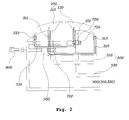
- FIG. 2 shows movement of oil in a default condition in which a CVVT is not controlled due to a problem with an engine, in which, first, hydraulic pressure by a detent valve 900 is removed, and the retarding oil line 300 for oil to move from the advancing chamber 110 and the retarding chamber 130 and the advancing oil line 310 for oil to move from the retarding chamber 130 to the advancing chamber 110 are connected to each other.
- the advancing oil channel 510 and the retarding oil channel 530 are closed by the diverter valves 700.
- the check valves 311 in the oil lines 300 prevent backflow of oil to the chambers 100 through the oil lines 300 even if the oil pressure of the corresponding chamber 100 has been increased.
- FIG. 3 shows movement of oil when an engine is in a normal state, in which the hydraulic pressure by the diverter valve 700 is removed, and oil is supplied to the advancing oil channel 510 of the advancing chamber 110 and the retarding oil channel 530 of the retarding chamber 130.
- the advancing oil line 310 and the retarding oil line 330 are closed by the diverter valves 700. Accordingly, when the CVVT is shaken by a change in cam torque, the internal hydraulic pressure of the chambers 100 is balanced and the intermediate phase is ensured.
- FIGS. 4 and 5 are graphs showing self-lock-possible periods according to the number of chambers 100 with a pressure adjusting means, that is, FIG. 4 is a graph when pressure adjusting means are provided for two chambers and FIG. 5 is a graph when pressure adjusting means are provided for all of three chambers.
- FIG. 4 is a graph when pressure adjusting means are provided for two chambers
- FIG. 5 is a graph when pressure adjusting means are provided for all of three chambers.
- the self-lock function is removed due to excessive oil pressure of the chamber without the pressure adjusting means in FIG. 4 , so it is impossible to advance the phase. Further, the amount of change in hydraulic pressure due to hysteresis of an oil pump is too large. However, in FIG. 5 , since all the chambers 100 are provided with a pressure adjusting means, the chambers 100 are not influenced by external oil pressure and hysteresis of an oil pump. Accordingly, self-lock is normally implemented in the entire period.
- all of chambers are provided with a pressure adjusting means and self-lock is always implemented regardless of the RPM of an engine and hydraulic conditions. Therefore, malfunction or stop of an engine does not occur, even if the engine has a problem, so the engine can be stably driven.
Landscapes
- Engineering & Computer Science (AREA)
- Mechanical Engineering (AREA)
- General Engineering & Computer Science (AREA)
- Valve Device For Special Equipments (AREA)
- Chemical Vapour Deposition (AREA)
Abstract
Description
- The present disclosure generally relates to an intermediate phase CVVT (Continuous Variable Valve Timing) particularly equipped with a variable oil pump in vehicles equipped with an intermediate phase CVVT.
- The statements in this section merely provide background information related to the present disclosure and may not constitute prior art.
- In general, a CVVT is applied to a vehicle to reduce exhaust gas and improve fuel efficiency and output. Recently, intermediate phase CVVT systems for removing limits in response and operation area of the existing CVVT systems are increasingly being used. Intermediate phase CVVTs control the position of a cam not at the most advanced (intake) position and the most delayed (exhaust) position, but an intermediate position, so response is quick and the use area of a cam can be increased, so fuel efficiency is improved and an exhaust gas is reduced.
- In an intermediate phase CVVT, a lock pin on the rotor is locked into a lock pin hole between the advance chamber and the delay chamber while the RPM of an engine is reduced, thereby preparing for later engine start. The action that the lock pin is automatically locked into the lock pin hole while the RPM of an engine reduces is called 'self-lock'.
- The self-lock is a function that allows a CVVT to mechanically return to an accurate position without specific adjustment so that operational stability of an engine can be maintained in periods where the CVVT system is not used, that is, when the engine is idling or is started.
- However, when the valve timing reaches the most delayed or retarded position without returning to the intermediate phase, and an engine of a vehicle is idling, a surge tank may not be vacuumized and the internal pressure of the surge tank may increase up to the atmospheric pressure, so the performance of a brake using the vacuum of the surge tank may be deteriorated.
- Further, when the valve timing reaches the most delayed position without returning to the intermediate phase, excessive overlap of valve timing may be generated between an intake valve and an exhaust valve, so the operational stability of the engine decreases and vibration of the engine increases, and in some cases the engine stops.
- That is, so-called self-lock of a lock pin in a intermediate phase CVVT may not be automatically performed, so when the rotor and the lock pin are positioned at the most advanced position or the most retarded position, the engine stops and the brake system may not operate because negative pressure is not normally generated.
- In particular, when a variable oil pump is used, oil pressure is largely changed in accordance with conditions of an engine, and this is because of hysteresis due to the variable oil pump. Accordingly, it is possible to set the intermediate phase by balancing the hydraulic pressure of chambers, but applying such a step may be difficult in practice.
- The foregoing is intended merely to aid in the understanding of the background of the present disclosure, and is not intended to mean that the foregoing is already known to those skilled in the art.
- Accordingly, the present disclosure proposes an intermediate phase adjustment apparatus of a CVVT. In some embodiments, this apparatus always achieves self-lock regardless of the RPM of an engine and hydraulic conditions by setting an intermediate phase and balancing hydraulic pressure of chambers even if a variable oil pump is used.
- The invention provides an intermediate phase adjustment apparatus of a CVVT according to claim 1. Further embodiments of the invention are described in the dependent claims.
- According to one aspect of the present disclosure, there is provided an intermediate phase adjustment apparatus of a CVVT including a pressure adjusting means or member for balancing pressure of chambers by selectively allowing oil to be moved from a chamber at relatively high pressure to a chamber at relatively low pressure by a pressure difference through an oil line through which the oil can move in only one direction between the chambers.
- The pressure adjusting means or member may be composed of the oil line and a diverter valve opening or closing the oil line.
- An oil channel for supplying oil for operating the CVVT may be formed in the chamber, the diverter valve may be disposed between the oil line and the oil channel, and the oil line and the oil channel may be selectively opened or closed.
- A detent valve for controlling the diverter valve may be connected to the diverter valve. When the detent valve generates hydraulic pressure and presses the diverter valve, the oil line may be blocked by the diverter valve, and when the hydraulic pressure by the detent valve is removed, the diverter valve may be returned by an elastic member connected to the diverter valve, so the oil channel is blocked.
- Outlets for discharging oil to corresponding chambers may be formed at a first side of the oil line and check valves may be disposed at a second side of the oil line to prevent backward flow of oil.
- The diverter valve may be disposed between the oil channel and the oil line for oil to flow into a specific chamber.
- The diverter valve may be disposed in all the chambers.
- The oil lines may be formed in all the chambers and connected to each other so that oil moves to pairs of chambers.
- The oil lines may be formed in all the chambers and connected to each other so that oil moves to pairs of chambers, and the diverter valves may be disposed in all the chambers, selectively open and close the oil lines and the oil channels, and set the intermediate phase of the CVVT by balancing pressure of the chambers, thereby implementing self-lock.
- According to one aspect of the present disclosure, there is provided an intermediate phase adjustment apparatus of a CVVT, in which advancing chambers and retarding chambers are provided in pairs, an advancing oil line and an advancing oil channel are formed in the advancing chambers, a retarding oil line and a retarding oil channel are formed in the retarding chambers, a diverter valve is disposed between the advancing oil lines and the advancing oil channels and between the retarding oil lines and the retarding oil channels, and when hydraulic pressure of the advancing chambers and the retarding chambers is not balanced, hydraulic pressure by a detent valve is removed and the diverter valve opens the oil lines, so oil moves from a chamber at relatively high pressure to a chamber at relatively low pressure, the hydraulic pressure is balanced, an intermediate phase is formed, and self-lock is always implemented.
- According to the intermediate phase adjustment apparatus of a CVVT of the present disclosure, all of chambers are provided with a pressure adjusting means and self-lock is always implemented regardless of the RPM of an engine and hydraulic conditions. Therefore, malfunction or stop of an engine does not occur, even if the engine has a problem, so the engine can be stably operated.
- The above and other objects, features and other advantages of the present disclosure will be more clearly understood from the following detailed description when taken in conjunction with the accompanying drawings, in which:
-
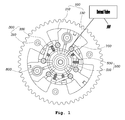
FIG. 1 is a view showing an intermediate phase adjustment apparatus of a CVVT according to an embodiment of the present disclosure; -
FIG. 2 is view showing supply of oil to an oil line shown inFIG. 1 ; -
FIG. 3 is view showing supply of oil to an oil channel shown inFIG. 1 ; and -
FIGS. 4 and5 are views showing self-lock-possible periods according to the number of chambers formed in an oil line. - An intermediate phase adjustment apparatus of a CVVT according to exemplary embodiments of the present disclosure is described hereafter with reference to the accompanying drawings.
- An intermediate phase adjustment apparatus of a CVVT (Continuous Variable Valve Timing) according to an embodiment of the present disclosure includes a pressure adjusting means or member that balances pressure of
chambers 100 by selectively allowing oil to be moved from one chamber (e.g. 100) at relatively high pressure to another chamber (e.g. 100) at relatively low pressure by a pressure difference through anoil line 300 through which the oil can move in only one direction between the chambers. The pressure adjusting means is composed of theoil line 300 and adiverter valve 700 that opens and/or closes theoil line 300. - As shown in
FIGS. 1 to 3 , anoil channel 500 for supplying oil for operating the CVVT is formed in thechamber 100 and thediverter valve 700 is disposed between theoil line 300 and theoil channel 500, so theoil line 300 and theoil channel 500 are selectively opened or closed. Adetent valve 900 for controlling thediverter valve 700 is connected to thediverter valve 700. When thedetent valve 900 generates hydraulic pressure and presses thediverter valve 700, theoil line 300 is blocked by thediverter valve 700, and when the hydraulic pressure by thedetent valve 900 is removed, thediverter valve 700 is returned by anelastic member 710 connected to thediverter valve 700, so theoil channel 500 is blocked. In particular, since theoil line 300 needs to allow oil to move in only one direction,outlets corresponding chambers 100 are formed at a first side of theoil line 300 andcheck valves - The
diverter valve 700 is disposed between theoil channel 500 and theoil line 300 for oil to flow into thechambers 100. In detail, thediverter valve 700 is disposed between an advancingoil line 310 and an advancingoil channel 510 for oil to flow into an advancingchamber 110, one of the advancingoil line 310 and the advancingoil channel 510 are selected by thediverter valve 700 in accordance with thedetent valve 900 supplies hydraulic pressure, and oil is supplied to the advancingchamber 110. Thediverter valve 700 is formed in all the advancingchambers 110 and retardingchambers 130. In an embodiment of the present disclosure, threechambers 100 each composed of a pair of advancingchamber 110 and retardingchamber 130 are exemplified, but the number of thechambers 100 may be freely changed in accordance with the environment or design. - The
oil lines 300 are formed in allchambers 100 and connected to each other so that oil moves to pairs ofchambers 100. Thediverter valves 700 are disposed in all the advancingchambers 110 and the retardingchambers 130 and selectively open/close theoil lines 300 and theoil channels 500 to set the intermediate phase of the CVVT by balancing the pressure of thechambers 100, so self-lock can be always achieved regardless of a problem with an engine, the RPM of the engine, and hydraulic conditions. - In this configuration, in more detail, pairs of advancing
chamber 110 and retardingchamber 130 are provided in the intermediate phase CVVT, the advancingoil line 310 and the advancingoil channel 510 are formed in the advancingchambers 110, and the retardingoil line 330 and the retardingoil channel 530 are formed in the retardingchamber 130. Thediverter valve 700 is disposed between the advancingoil line 310 and the advancingoil channel 510 and between the retardingoil line 330 and the retardingoil channel 530. If hydraulic pressure is not balanced between the advancingchamber 110 and the retardingchamber 130, the hydraulic pressure by thedetent valve 900 is removed and thediverter valve 700 opens theoil line 300 and oil moves from thechamber 100 at relatively high pressure to thechamber 100 at relatively low pressure, so the hydraulic pressure is balanced, and an intermediate phase is obtained and self-lock is always achieved regardless of the RPM of an engine or hydraulic conditions. - In the present disclosure, an intermediate phase CVVT is equipped with a variable oil pump (not shown). When a variable oil pump is used, changes in oil pressure according to conditions of an engine are large by hysteresis due to the variable oil pump. Accordingly, when engine has a problem and the CVVT is not controlled, the intermediate phase should be obtained and a
lock pin 800 should be locked in order to prevent malfunction or stop of the engine, but self-lock may be applied to only some of three chambers due to limits in manufacturing cost and layout in the cam torque balance type of intermediate phase CVVTs of the related art. Accordingly, a pressure adjusting means for adjusting balance of an advancing chamber and a retarding chamber is provided in only some of chambers, but when excessive oil pressure is applied to the other chambers without the pressure adjusting means, the chambers with the pressure adjusting means have difficulty in moving to the intermediate position against the excessive hydraulic pressure of the chambers with the pressure reducing means. Accordingly, in the present disclosure, a pressure adjusting means is preferably provided for all the advancingchambers 110 and the retardingchambers 130 of the CVVT so that self-lock is always achieved regardless of the RPM of an engine and hydraulic conditions. - This configuration is shown in
FIGS. 2 and3 .FIG. 2 shows movement of oil in a default condition in which a CVVT is not controlled due to a problem with an engine, in which, first, hydraulic pressure by adetent valve 900 is removed, and the retardingoil line 300 for oil to move from the advancingchamber 110 and the retardingchamber 130 and the advancingoil line 310 for oil to move from the retardingchamber 130 to the advancingchamber 110 are connected to each other. In this process, the advancingoil channel 510 and the retardingoil channel 530 are closed by thediverter valves 700. Accordingly, when the CVVT is shaken by a change in cam torque, the oil in thechamber 100 at relatively high pressure moves to thechamber 100 at relatively low pressure, so pressure is balanced and the intermediate phase is ensured. Thecheck valves 311 in theoil lines 300 prevent backflow of oil to thechambers 100 through theoil lines 300 even if the oil pressure of thecorresponding chamber 100 has been increased. - In contrast,
FIG. 3 shows movement of oil when an engine is in a normal state, in which the hydraulic pressure by thediverter valve 700 is removed, and oil is supplied to the advancingoil channel 510 of the advancingchamber 110 and the retardingoil channel 530 of the retardingchamber 130. In this process, the advancingoil line 310 and the retardingoil line 330 are closed by thediverter valves 700. Accordingly, when the CVVT is shaken by a change in cam torque, the internal hydraulic pressure of thechambers 100 is balanced and the intermediate phase is ensured. -
FIGS. 4 and5 are graphs showing self-lock-possible periods according to the number ofchambers 100 with a pressure adjusting means, that is,FIG. 4 is a graph when pressure adjusting means are provided for two chambers andFIG. 5 is a graph when pressure adjusting means are provided for all of three chambers. Although the case when pressure adjusting means are provided for two chambers is compared, it is obvious that the self-lock-impossible period increases when the pressure adjusting means is provided for one or no chamber, so the case when the pressure reducing means are provided for two chamber is representatively selected and compared. - As clearly shown in
FIGS. 4 and5 , the self-lock function is removed due to excessive oil pressure of the chamber without the pressure adjusting means inFIG. 4 , so it is impossible to advance the phase. Further, the amount of change in hydraulic pressure due to hysteresis of an oil pump is too large. However, inFIG. 5 , since all thechambers 100 are provided with a pressure adjusting means, thechambers 100 are not influenced by external oil pressure and hysteresis of an oil pump. Accordingly, self-lock is normally implemented in the entire period. - As described above, according to one form of the intermediate phase adjustment apparatus of a CVVT of the present disclosure, all of chambers are provided with a pressure adjusting means and self-lock is always implemented regardless of the RPM of an engine and hydraulic conditions. Therefore, malfunction or stop of an engine does not occur, even if the engine has a problem, so the engine can be stably driven.
- Although embodiments of the present disclosure have been described for illustrative purposes, those skilled in the art will appreciate that various modifications, additions and substitutions are possible, without departing from the scope and spirit of the disclosure as disclosed in the accompanying claims.
Claims (11)
- An intermediate phase adjustment apparatus of a Continuous Variable Valve Timing, the apparatus comprising:a pressure adjusting means comprising a plurality of chambers having a first chamber and a second chamber, each chamber containing oil, the pressure adjusting means comprising an oil line and balancing pressure of the chambers by selectively allowing oil to be moved from the first chamber at relatively high pressure to the second chamber at relatively low pressure by a pressure difference through the oil line through which the oil moves in only one direction between the first and second chambers.
- The apparatus of claim 1, wherein the pressure adjusting means comprises a diverter valve opening or closing the oil line.
- The apparatus of claim 2, wherein each chamber forms an oil channel for supplying oil for operating the Continuous Variable Valve Timing, the diverter valve is disposed between the oil line and the oil channel, and the oil line and the oil channel are selectively opened or closed.
- The apparatus of claim 2 or 3, further comprising an elastic member and a detent valve operable to control the diverter valve and being connected to the diverter valve, the apparatus having a first state in which the detent valve generates hydraulic pressure and presses the diverter valve, and the oil line is blocked by the diverter valve, the apparatus having a second state in which the hydraulic pressure by the detent valve is removed, and the diverter valve is returned by the elastic member connected to the diverter valve so the oil channel is blocked.
- The apparatus of one of claims 2-4, wherein the pressure adjusting means comprises a plurality of outlets for discharging oil to corresponding chambers, the oil line having a first side forming a first outlet, and the oil line having a second side comprising check valves to prevent backward flow of oil.
- The apparatus of one of claims 2 to 5 in combination with claim 3, wherein the diverter valve is disposed between the oil channel and the oil line for oil to flow into one chamber.
- The apparatus of one of claims 2 to 6, wherein one diverter valve is disposed in all of the chambers.
- The apparatus of one of claims 1 to 7, wherein each pair of chambers includes one oil line such that a plurality of oil lines are formed in all the chambers, all oil lines being connected to each other so that oil moves to pairs of chambers.
- The apparatus of one of claims 2 to 8, wherein each pair of chambers includes one oil line such that a plurality of oil lines are formed in all the chambers, all oil lines being connected to each other so that oil moves to pairs of chambers, and
respective diverter valves are disposed in all the chambers and selectively open and close the corresponding oil lines and the corresponding oil channels to set the intermediate phase of the Continuous Variable Valve Timing by balancing pressure of the chambers to implement self-lock. - The apparatus of one of claims 1 to 9, wherein the pressure adjusting means comprises a plurality of first chambers and of second chambers provided as advancing chambers and retarding chambers, respectively, which are provided in pairs.
- The apparatus of claim 10, wherein the apparatus further comprises
an advancing oil line and an advancing oil channel are formed in the advancing chambers, a retarding oil line and a retarding oil channel are formed in the retarding chambers, a plurality of diverter valves wherein one diverter valve is disposed between each advancing oil line and each advancing oil channel, and another diverter valve being disposed between each retarding oil line and each retarding oil channel, each diverter valve operable by way of a detent valve; and
when hydraulic pressure of the advancing chambers and the retarding chambers is unbalanced, hydraulic pressure by the detent valve is removed and the respective diverter valve opens the respective oil line, so oil moves from a first chamber at relatively high pressure to a second chamber at relatively low pressure, when the hydraulic pressure is balanced, an intermediate phase is formed, and self-lock is implemented.
Applications Claiming Priority (1)
| Application Number | Priority Date | Filing Date | Title |
|---|---|---|---|
| KR20150091600 | 2015-06-26 |
Publications (2)
| Publication Number | Publication Date |
|---|---|
| EP3109421A2 true EP3109421A2 (en) | 2016-12-28 |
| EP3109421A3 EP3109421A3 (en) | 2017-01-11 |
Family
ID=54705005
Family Applications (1)
| Application Number | Title | Priority Date | Filing Date |
|---|---|---|---|
| EP15195806.3A Withdrawn EP3109421A3 (en) | 2015-06-26 | 2015-11-23 | Intermediate phase adjustment apparatus of cvvt |
Country Status (3)
| Country | Link |
|---|---|
| US (1) | US20160376938A1 (en) |
| EP (1) | EP3109421A3 (en) |
| CN (1) | CN106285813A (en) |
Families Citing this family (2)
| Publication number | Priority date | Publication date | Assignee | Title |
|---|---|---|---|---|
| DE102017112471B3 (en) | 2017-06-07 | 2018-09-13 | Schaeffler Technologies AG & Co. KG | Phaser |
| CN111255760B (en) * | 2020-03-17 | 2024-11-19 | 王浩坤 | Lineless hydraulics |
Family Cites Families (3)
| Publication number | Priority date | Publication date | Assignee | Title |
|---|---|---|---|---|
| DE10337587A1 (en) * | 2003-08-16 | 2005-03-10 | Ina Schaeffler Kg | Camshaft phase adjuster with freewheel for internal combustion engine has stator with timing sprocket wheel and with chambers accommodating vanes on rotor mounted on camshaft |
| DE112012001003T5 (en) * | 2011-04-01 | 2014-03-13 | Borgwarner Inc. | Use of torsional energy to move an actuator |
| JP6134398B2 (en) * | 2013-06-19 | 2017-05-24 | ボーグワーナー インコーポレーテッド | Variable camshaft timing mechanism with lock pin engaged by hydraulic pressure |
-
2015
- 2015-11-06 US US14/935,007 patent/US20160376938A1/en not_active Abandoned
- 2015-11-23 EP EP15195806.3A patent/EP3109421A3/en not_active Withdrawn
- 2015-11-25 CN CN201510828901.4A patent/CN106285813A/en active Pending
Non-Patent Citations (1)
| Title |
|---|
| None |
Also Published As
| Publication number | Publication date |
|---|---|
| CN106285813A (en) | 2017-01-04 |
| EP3109421A3 (en) | 2017-01-11 |
| US20160376938A1 (en) | 2016-12-29 |
Similar Documents
| Publication | Publication Date | Title |
|---|---|---|
| JP4544294B2 (en) | Valve timing adjustment device | |
| JP2018145906A (en) | Hydraulic oil control valve and valve timing adjustment device using the same | |
| US20180266283A1 (en) | Variable camshaft timing mechanism with a lock pin engaged by oil pressure | |
| CN105556073B (en) | Multiple locking of a camshaft adjuster and method for operating a camshaft adjuster | |
| JP5747520B2 (en) | Valve timing adjustment device | |
| CN110192010A (en) | valve timing adjustment device | |
| JP4492684B2 (en) | Valve timing adjustment device | |
| JP2009236045A (en) | Valve timing adjusting apparatus | |
| EP2578844B1 (en) | Fuel system of a jet engine | |
| US20160376938A1 (en) | Intermediate phase adjustment apparatus of cvvt | |
| JP2012122454A (en) | Valve timing adjusting device | |
| US7025032B2 (en) | Priority oil system | |
| JP5772786B2 (en) | Oil control valve | |
| CN106368824B (en) | Intermediate phase adjusting device of CVVT | |
| US9909464B2 (en) | Intermediate phase adjustment apparatus of CVVT | |
| JP2008069651A (en) | Valve timing adjustment device | |
| US20160376942A1 (en) | Apparatus for opening and closing channel | |
| JP7091634B2 (en) | Hydraulic control valve | |
| JP2012251464A (en) | Control apparatus for internal combustion engine | |
| CN106285817B (en) | Method of controlling lock pin of continuous variable valve timing system | |
| US9038585B2 (en) | Valve timing control apparatus | |
| JP5397559B2 (en) | Control device for internal combustion engine | |
| KR20160112062A (en) | Variable valve timing system for dual fuel engine | |
| JP6589342B2 (en) | Valve timing control device | |
| KR101601556B1 (en) | Apparatus for preventing oil backdraft in intermediate phase cvvt |
Legal Events
| Date | Code | Title | Description |
|---|---|---|---|
| PUAI | Public reference made under article 153(3) epc to a published international application that has entered the european phase |
Free format text: ORIGINAL CODE: 0009012 |
|
| PUAL | Search report despatched |
Free format text: ORIGINAL CODE: 0009013 |
|
| AK | Designated contracting states |
Kind code of ref document: A2 Designated state(s): AL AT BE BG CH CY CZ DE DK EE ES FI FR GB GR HR HU IE IS IT LI LT LU LV MC MK MT NL NO PL PT RO RS SE SI SK SM TR |
|
| AX | Request for extension of the european patent |
Extension state: BA ME |
|
| AK | Designated contracting states |
Kind code of ref document: A3 Designated state(s): AL AT BE BG CH CY CZ DE DK EE ES FI FR GB GR HR HU IE IS IT LI LT LU LV MC MK MT NL NO PL PT RO RS SE SI SK SM TR |
|
| AX | Request for extension of the european patent |
Extension state: BA ME |
|
| RIC1 | Information provided on ipc code assigned before grant |
Ipc: F01L 1/344 20060101AFI20161207BHEP |
|
| 17P | Request for examination filed |
Effective date: 20170711 |
|
| RBV | Designated contracting states (corrected) |
Designated state(s): AL AT BE BG CH CY CZ DE DK EE ES FI FR GB GR HR HU IE IS IT LI LT LU LV MC MK MT NL NO PL PT RO RS SE SI SK SM TR |
|
| 17Q | First examination report despatched |
Effective date: 20171214 |
|
| STAA | Information on the status of an ep patent application or granted ep patent |
Free format text: STATUS: THE APPLICATION IS DEEMED TO BE WITHDRAWN |
|
| 18D | Application deemed to be withdrawn |
Effective date: 20180425 |