EP3109079B1 - Air discharge device - Google Patents
Air discharge device Download PDFInfo
- Publication number
- EP3109079B1 EP3109079B1 EP15173923.2A EP15173923A EP3109079B1 EP 3109079 B1 EP3109079 B1 EP 3109079B1 EP 15173923 A EP15173923 A EP 15173923A EP 3109079 B1 EP3109079 B1 EP 3109079B1
- Authority
- EP
- European Patent Office
- Prior art keywords
- fin
- discharge device
- air discharge
- control
- actuating
- Prior art date
- Legal status (The legal status is an assumption and is not a legal conclusion. Google has not performed a legal analysis and makes no representation as to the accuracy of the status listed.)
- Active
Links
Images


Classifications
-
- B—PERFORMING OPERATIONS; TRANSPORTING
- B60—VEHICLES IN GENERAL
- B60H—ARRANGEMENTS OF HEATING, COOLING, VENTILATING OR OTHER AIR-TREATING DEVICES SPECIALLY ADAPTED FOR PASSENGER OR GOODS SPACES OF VEHICLES
- B60H1/00—Heating, cooling or ventilating [HVAC] devices
- B60H1/34—Nozzles; Air-diffusers
- B60H1/3414—Nozzles; Air-diffusers with means for adjusting the air stream direction
- B60H1/3421—Nozzles; Air-diffusers with means for adjusting the air stream direction using only pivoting shutters
-
- B—PERFORMING OPERATIONS; TRANSPORTING
- B60—VEHICLES IN GENERAL
- B60H—ARRANGEMENTS OF HEATING, COOLING, VENTILATING OR OTHER AIR-TREATING DEVICES SPECIALLY ADAPTED FOR PASSENGER OR GOODS SPACES OF VEHICLES
- B60H1/00—Heating, cooling or ventilating [HVAC] devices
- B60H1/34—Nozzles; Air-diffusers
- B60H2001/3471—Details of actuators
- B60H2001/3478—Details of actuators acting on additional damper doors
Definitions
- Air discharge device for conducting and controlling an airflow out of an air feed shaft or an air feed duct in a heating, ventilation or air-conditioning installation.
- Air discharge devices are provided in land, water and air vehicles, such as automobiles, boats or aircrafts.
- An air discharge device for controlling and adjusting an airflow comprises at least one control element.
- one control element provides controlling of horizontal and vertical fins as well as controlling the amount of an airflow by adjusting closing means.
- Such control elements are often arranged slidably or pivotably on a pivotable horizontal control fin. Thereby, if the control element is moved in vertical direction the control fin is tilted. If the control element is moved in horizontal direction, vertical fins are tilted.
- control element often comprises also a wheel wherein the wheel is coupled with closing means. Thereby, if the wheel is rotated the closing means open and close an air feed shaft.
- closing means open and close an air feed shaft.
- DE 20 2010 000 445 U1 discloses an air discharge device with a single control element.
- the control element is rotatably supported in a bearing of a fin arrangement.
- the fin arrangement can be tilted by means of the control element. Thereby, the control element is moved in vertical direction.
- control element comprises two protruding elements and a vertical fin is supported between these protruding elements. Rotating the control element causes tilting of vertical fins.
- control element comprises a guidance in a cylindrical portion of the control element. A pin is supported in the guidance and is coupled over rods with a pivotable plate. If the control element is moved along its rotation axis, the plate opens and closes an air feed shaft.
- DE 10 2007 019 602 B3 discloses a round air nozzle with a cone-shaped air guide element and a plug, which can be moved in direction of the airflow and the cone-shaped air guide element, to control the amount of the airflow. However, the control of the airflow direction is carried out by tilting the cone-shaped air guide element.
- DE 10 2007 019 602 B3 does not disclose fins.
- an air discharge device comprising pivotably supported fins, extending orthogonally to each other, wherein one of the fins is a control fin, and a control element, controlling the fins for adjusting the direction of an airflow and controlling closing means comprising at least one flap for adjusting the extent and amount of the airflow, the control element comprises:
- the air discharge device allows a control of the airflow by pivoting the fins through a displacement of the slider.
- the air discharge device also enables a control of the amount of the airflow through a simple push-push mechanism wherein the actuating element can be pushed into the slider. If the slider is pressed downwards the control fin is also pivoted downwards. For example, the slider is pressed downwards by the actuating element. If a force is applied orthogonally to the longitudinal axis of the control fin the control fin is pivoted and the slider does not change its position along the control fin. If a force is applied in the longitudinal direction of the control fin on the slider or the actuating element, the slider moves along the control fin. Thus, fins arranged orthogonally to the control fin are pivoted by means of the actuating member.
- the actuating element protrudes in an inactive state at least to a certain distance of the bearing of the slider.
- the closing means fully opens or closes an air feed shaft or an air feed duct of a heating, ventilation or air-conditioning installation. If a force is applied on the actuating element, the actuating element is moved along the bearing whereas the actuating member is moved away from the slider and thus enables a corresponding movement of the connecting element.
- the actuating element is brought to a position in which the actuating element protrudes a second distance of the bearing of the slider. However, the second distance in the displaced position of the actuating element is less than in the inactive state.
- the connecting element then enables pivoting of the at least one flap wherein the pin of the connecting element is also moved due to the movement of the actuating member and, thus, the pin causes the at least one flap to pivot.
- the flap is pivotally arranged.
- the flap cannot be displaced according to the movement of the other components in the same direction.
- the curved recess in the pivoting member enables pivoting of the flap wherein the pin is guided in the recess.
- the guide element is guided in the guidance of the control fin and is also guided in the heart-shaped cam, which enables, together with the spring means, a push-push mechanism.
- the design of the connecting element comprising a curved recess enables the closing means to open and close in every position of the fins, especially the fins arranged orthogonally to the control fin.
- intermediate positions of the closing means, especially the at least one flap, can also be accomplished.
- the spring means can comprise elastic means, like rubber elements, or pneumatic, magnetic or mechanical elements.
- said spring means comprise at least one compression spring.
- the actuating element can comprise at least one guide member guiding the actuating element and the actuating member.
- the guide member especially ensures that the actuating member does not change its parallel arrangement relative to the actuating element when a space between the actuating element and the actuating member is changed.
- the at least one guide element can be arranged on the actuating member wherein the guide element is supported in a bearing in the actuating element.
- at least one compression spring can encompass such a guide member.
- the air discharge device comprises at least one telescopic guide rod, one end of said telescopic guide rod is connected to the actuating element and the other end of said telescopic guide rod is connected to the actuating member.
- a telescopic guide rod is a special embodiment of a guide member, whereas the guide member is only connected with either the actuating member or the actuating element and the telescopic guide rod is connected with the actuating member and the actuating element.
- the at least one compression spring encompasses the at least one guide rod.
- the closing means comprises two flaps, wherein said flaps are supported pivotally by a common rotation axis and the curved recesses of the pivoting members of said flaps are arranged opposite to each other and facing each other. A movement of the connecting element enables pivoting of both flaps which are pivoted about a common rotation axis.
- the connecting element comprises two pins arranged on opposite sides of said connecting element wherein the pins extend parallelly to the rotation axis.
- Each pin of the connecting element may comprise a longitudinal axis which is arranged parallelly to the longitudinal axis of the other pin.
- the fin coupled with the actuating member comprises a recess and a rod, wherein said rod is supported in a fork of said actuating member.
- the recess ensures that the at least one fin extending orthogonally to the control fin can be pivoted in every position of the control fin.
- the actuating member may comprise a plate-shaped form. On the side facing the actuating element the actuating member is at least connected with the spring means. On the other side of the actuating member the pin supported in the curved recess of the connecting element is arranged. Further, coupling means for coupling the actuating member with the at least one fin extending orthogonally to the control fin are arranged on the same side of the actuating member as said pin.
- the coupling means comprise the fork.
- the connecting element may comprise an open structure.
- An open structure ensures that the airflow is not disturbed by means of the control element.
- the connecting element extends parallelly to the fins extending orthogonally to the control fin whereby an airflow disturbance is reduced.
- control fin is coupled with at least one fin extending parallelly to the control fin and/or the fin coupled with the actuating member is coupled with at least one fin extending parallelly to said fin.
- connection rod couples said fins.
- control fin comprises a guide section comprising said guidance of the control fin and defining the displacement path of the slider.
- the guide section is located in the middle of the control fin.
- the guide section may be constructed as a bridge connecting two control fin sections extending from the central guide section to the exterior sides of the control fin.
- the bridge connects the two control fin sections in such a manner that a defined space exits between the lateral sides of the control fin sections facing each other.
- the actuating element extending at least partially through the slider abuts on the lateral sides of the control fin sections facing each other during displacement of the slider.
- the space between the control fin sections defines the displacement path of the slider.
- At least one of the fins, flaps, slider, actuating element, actuating member, connecting element and guide element consists of plastic material.
- Other materials may also be applied for the components of the air discharge device, for example metals and alloys.
- compression springs consist of metal and spring steel, respectively.
- FIGs. 1-8 show an exemplary embodiment of an air discharge device 10 and components of the air discharge device 10, wherein like reference signs refer to like components. Moreover, only components are shown and explained which are necessary to understand the teachings disclosed herein.
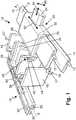
- Fig. 1 shows an air discharge device 10.
- the air discharge device 10 comprises a housing (not shown) and fins 12, 14, 16 pivotally supported in the housing. Fin 12 is supported by bearing pins 13 in bearing holes on opposite sidewalls of the housing. Fin 14 extending parallelly to fin 12 is supported by bearing pins 15 in bearing holes on said opposite sidewalls of the housing. Fins 16 extending orthogonally to fin 12 and fin 14 are supported by bearing pins 17 in bearing holes on opposite walls of the housing. Fins 12, 14 and 16 can be pivoted by means of a control element 20.
- the control element 20 also provides for the control of closing means 18.
- Control fin 12 comprises two control fin sections extending from a central guide section to the exterior sides of the control fin 12.
- the two control fin sections are connected by a connection bridge 66 ( Figs. 3 and 4 ).
- the connection bridge 66 comprises a guidance 58 in which a guide element 60 of the control element 20 is partially inserted.
- the connection bridge 66 connects the two control fin sections in such a manner that a defined space exits between the lateral sides of the control fin sections facing each other.
- Control fin 12 is coupled with fin 14 by means of a connection rod (not shown).
- One of the fins 16 comprises a recess 40 and a rod 42 closing the recess 40.
- the rod 42 is supported by a fork 44 of the control element 20.
- the recess 40 ensures that the fork 44 does not abut against the sides of said fin 16.
- Said fin 16 is coupled with the other fins 16 by means of a connection rod 46.
- Connection rod 46 comprises at least four bearing holes 47. Bearing pins of fins 16 are supported in said bearing holes 47 so that the pivoting of said fin 16 causes a synchronic pivoting of the other fins 16.
- the bearing pins of fins 16 run parallelly to the pivot axis of fins 16 extending through the pins 17.
- Closing means 18 comprise two flaps 30 and 32. Flaps 30 and 32 are pivotally supported by bearing pins 31 and 33 in bearing holes on said opposite sidewalls of the housing. Flap 30 comprises bearing pin 31 and flap 32 comprises bearing pin 33. Flap 30 comprises an opening 72 in which a corresponding pin of flap 32 is supported ( Fig. 6 ). The flaps 30 and 32 comprises a common rotation axis B extending through the bearing pins 31 and 33, the opening 72 and the corresponding pin (not shown). The flaps 30 and 32 can be pivoted by means of the control element 20, especially by displacement of a connecting element 28. For this purpose, the flaps 30 and 32 comprises curved pivoting members 82 and 84.
- the pivoting members 82 and 84 comprise a curved recess 36 and a curved recess 38, respectively. Flaps 30 and 32 can be pivoted from an open position, shown in Fig.1 , to a closed position (not shown) wherein the flaps 30 and 32 move away from each other.
- the control element 20 comprises an actuating element 24, a slider 22, an actuating member 26 and the connecting element 28.
- the control element 20 also comprises the guide element 60, compression springs 62, the fork 44 and a pin 64.
- Slider 22 is slidably supported on the control fin 12.
- Slider 22 has two recesses 54 through which the control fin sections extend into the slider 22.
- Slider 22 also has a bearing 48 through which the actuating element 24 extends into the slider 22 ( Fig. 2 ).
- slider 22 can be moved along control fin 12 due to the space defined between the lateral sides of the control fin sections facing each other wherein the actuating element 24 abuts against the lateral sides of the control fin sections in its end positions.
- the actuating element 24 which extends at least partially through the slider 22 abuts on the lateral sides of the control fin sections facing each other during displacement of the slider 22.
- the space between the control fin sections defines the displacement path of the slider 22.
- Stopper elements may comprise a rubber layer, a rubber coating or the like.
- Actuating element 24 comprises a heart-shaped cam 50 and two bearings 52.
- Compression springs 62 are supported in the bearings 52 and abuts on one end against bearing surfaces 56.
- the other end of the compression springs 62 is connected to the actuating member 26 ( Figs. 4 and 5 ).
- the guide element 60 is guided and partially inserted in the heart-shaped cam 50 and the guidance 58 of the connection bridge 66.
- Slider 22 may comprise two parts of plastic material which are connected by means of ultrasonic welding, bonding or heating. Slider 22 comprises an open rear side facing the connecting element 28.
- the actuating member 26 has a plate-like shape and abuts against the circumferential edge of the open rear side of the slider 22.
- the actuating member 26 comprises the fork 44 which encompasses the rod 42 of fin 16.
- the actuating member 26 also comprises two support bars 70. The support bars 70 are connected with the pin 64.
- the connecting element 28 comprises a curved section 35 facing the actuating member 26 and a curved recess 34. Pin 64 coupled with the actuating member 26 is received in the curved recess 34. Thus, in every pivoted position of the control fin 12 displacement movement of the actuating member 26 can be transmitted to the connecting element 28.
- the connecting element 28 can be guided in the housing of the air discharge device 10.
- the air discharge device 10 comprises at least one guide rail in which the connecting element 28 is partially supported.
- the connecting element 28 comprises an open structure which enables an airflow to pass.
- the connecting element 28 also comprises two nose elements 74 and 76 serving as support bars for a pin 78 and a pin 80.
- Pin 78 and pin 80 are supported in the curved recesses 36 and 38 of pivoting member 82 and pivoting member 84, respectively. Pins 78 and 80 are arranged opposite to each other. Further, pin 78 and pin 80 comprising different parallel longitudinal axis. Due to the rotatable mounting of the flaps 30 and 32 any movement of the connecting element 28 causes pivoting of the flaps 30 and 32.
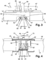
- Fig. 2 shows a sectional view of the control fin 12, the slider 22 and the actuating element 24.
- the actuating element 24 comprises a wall 68 which is arranged inside the slider 22.
- the wall 68 increases the cross section of the actuating element 24 and prevents the actuating element 24 to be pressed out of the slider 22 by means of the compression springs 62.
- Fig. 3 shows a top view of the control fin 12 and parts of the control element 20, namely the actuating element 24, compression springs 62, guide element 60, actuating member 26, fork 44, pin 68 and connecting element 28. Further, Fig. 3 shows fin 14 and connection rod 46.
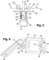
- Fig. 4 shows a sectional view of the control fin 12 and parts of the control element 20 and Fig. 5 shows a further top view of parts of the control element 20. Fig. 5 also shows the connection rod 46.
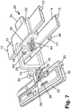
- Fig. 6 shows a perspective view of parts of the control element 20 and the flap 30 and Fig. 7 shows a further perspective view of components of the air discharge device 10 without the housing and fins 16.
- Fig. 8 shows a side-view of the control element 20 and components of the air discharge device 10 namely control fin 12 and fin 14.
- Figs. 1-8 show the orientation of fins 12, 14, 16 and flaps 30, 32 in a condition without any change, namely in an initial position.
- an airflow passes the air discharge device 10 without any deviation. If a force is applied on the actuating element 24 or the slider 22 in a vertical direction 90, fins 12 and 14 are pivoted. Then, the airflow is deviated downwards. If a force is applied on the actuating element 24 or the slider 22 in a horizontal direction 92, fins 16 are pivoted. Thereby, slider 22 is moved in the horizontal direction 92. In addition, fork 44 coupled with the actuating element 24 and thus with the slider 22 is moved in the same horizontal direction 92.
- actuating element 24 is pressed in the slider 22. After a defined displacement of actuating element 24, actuating element 24 abuts against the actuating member 26 and moves the actuating member 26 towards the connecting element 28 and away from the slider 22. Then, connecting element 28 is moved by pin 64 in the same direction 94. Movement of connecting element 28 causes pivoting of flaps 30 and 32.
- the flaps 30 and 32 are passed from the initial position in a closed position. In the initial position the flaps 30, 32 extending in a horizontal plane and in the closed position extending in a vertical plane. Flaps 30 and 32 close an air feed duct in the closed position so that the airflow for the air discharge device 10 is interrupted.
- the guide element 60 follows the heart-shaped cam 50. After the actuating element 24 has exceed a maximal displacement in direction 94, guide element 60 is transferred in a lower section of heart-shaped cam 50 and accordingly in a section of heart-shaped cam 50 facing the front side of air discharge device 10. If the guide element 60 is transferred in the lower section the actuating element 24 is hold in that position wherein the extend of the actuating element 24 which is located in the slider 22 is greater than in the initial position. The transferred position of the actuating member 26 and the connecting member 28 is maintained until a force is applied in direction 94 again.
- actuating element 24 is displaced in the direction 94 towards the connecting element 28 by a small distance. This displacement enables the guide element 60 to unlock the closed condition wherein guide element 60 is transferred to the left path of heart-shaped cam 50 ( Fig. 4 ). After that, actuating element 24 can move back to its initial position whereas actuating member 26 also moves back to its initial position. Thereby, connecting element 28 is transferred to its initial position and flaps 30 and 32 are pivoted to reach their initial position.
Landscapes
- Physics & Mathematics (AREA)
- Thermal Sciences (AREA)
- Engineering & Computer Science (AREA)
- Mechanical Engineering (AREA)
- Air-Flow Control Members (AREA)
Description
- It is disclosed an air discharge device for conducting and controlling an airflow out of an air feed shaft or an air feed duct in a heating, ventilation or air-conditioning installation. Air discharge devices are provided in land, water and air vehicles, such as automobiles, boats or aircrafts.
- An air discharge device for controlling and adjusting an airflow comprises at least one control element. In many known installations, one control element provides controlling of horizontal and vertical fins as well as controlling the amount of an airflow by adjusting closing means. Such control elements are often arranged slidably or pivotably on a pivotable horizontal control fin. Thereby, if the control element is moved in vertical direction the control fin is tilted. If the control element is moved in horizontal direction, vertical fins are tilted.
- In such installations, the control element often comprises also a wheel wherein the wheel is coupled with closing means. Thereby, if the wheel is rotated the closing means open and close an air feed shaft. Such an air discharge device is disclosed in
DE 20 2013 100 257 U1 . -
DE 20 2010 000 445 U1 discloses an air discharge device with a single control element. The control element is rotatably supported in a bearing of a fin arrangement. The fin arrangement can be tilted by means of the control element. Thereby, the control element is moved in vertical direction. - Furthermore, the control element comprises two protruding elements and a vertical fin is supported between these protruding elements. Rotating the control element causes tilting of vertical fins. Further, the control element comprises a guidance in a cylindrical portion of the control element. A pin is supported in the guidance and is coupled over rods with a pivotable plate. If the control element is moved along its rotation axis, the plate opens and closes an air feed shaft.
-
DE 10 2007 019 602 B3 discloses a round air nozzle with a cone-shaped air guide element and a plug, which can be moved in direction of the airflow and the cone-shaped air guide element, to control the amount of the airflow. However, the control of the airflow direction is carried out by tilting the cone-shaped air guide element.DE 10 2007 019 602 B3 does not disclose fins. - The state of the art discloses installations with many components to control the direction of an airflow and to adjust the extent and amount of the airflow. Furthermore, known air discharge devices are complex in their kinematics.
- Thus, it is an object to provide an air discharge device with fins and closing means for controlling an airflow wherein the control is carried out with less parts in a simple manner and wherein the control parts do not disturb the airflow.
- The object is fulfilled by an air discharge device comprising pivotably supported fins, extending orthogonally to each other, wherein one of the fins is a control fin, and a control element, controlling the fins for adjusting the direction of an airflow and controlling closing means comprising at least one flap for adjusting the extent and amount of the airflow, the control element comprises:
- a slider with a bearing slidable along the control fin,
- a slidable actuating element supported in said bearing, wherein the actuating element comprises a heart-shaped cam,
- a guide element, slidably supported in a guidance of the control fin,
- spring means connected on one side with the actuating element and connected on the other side with an actuating member, wherein the actuating member is coupled with at least one fin, extending orthogonally to the control fin, and
- a connecting element extending orthogonally to the control fin and coupled with the actuating member and at least one flap,
- the connecting element is slidably supported orthogonally to the control fin,
- the guidance of the control fin extends parallelly to the longitudinal axis of the control fin,
- one end of the guide element is supported in said guidance and the other end is guided in said heart-shaped cam,
- the actuating member comprises a pin supported in a curved recess of the connecting element, and
- the connecting element comprises at least one pin supported in a curved recess of a pivoting member of the flap.
- The air discharge device allows a control of the airflow by pivoting the fins through a displacement of the slider. The air discharge device also enables a control of the amount of the airflow through a simple push-push mechanism wherein the actuating element can be pushed into the slider. If the slider is pressed downwards the control fin is also pivoted downwards. For example, the slider is pressed downwards by the actuating element. If a force is applied orthogonally to the longitudinal axis of the control fin the control fin is pivoted and the slider does not change its position along the control fin. If a force is applied in the longitudinal direction of the control fin on the slider or the actuating element, the slider moves along the control fin. Thus, fins arranged orthogonally to the control fin are pivoted by means of the actuating member.
- The actuating element protrudes in an inactive state at least to a certain distance of the bearing of the slider. In the inactive state, the closing means fully opens or closes an air feed shaft or an air feed duct of a heating, ventilation or air-conditioning installation. If a force is applied on the actuating element, the actuating element is moved along the bearing whereas the actuating member is moved away from the slider and thus enables a corresponding movement of the connecting element. After a defined displacement due to the design of the heart-shaped cam, the actuating element is brought to a position in which the actuating element protrudes a second distance of the bearing of the slider. However, the second distance in the displaced position of the actuating element is less than in the inactive state. The connecting element then enables pivoting of the at least one flap wherein the pin of the connecting element is also moved due to the movement of the actuating member and, thus, the pin causes the at least one flap to pivot. The flap is pivotally arranged. The flap cannot be displaced according to the movement of the other components in the same direction. The curved recess in the pivoting member enables pivoting of the flap wherein the pin is guided in the recess. After that, a force can be applied again on the actuating element so that the actuating element and the other components connected or coupled with the actuating element return to the inactive position.
- The guide element is guided in the guidance of the control fin and is also guided in the heart-shaped cam, which enables, together with the spring means, a push-push mechanism. Moreover, the design of the connecting element comprising a curved recess enables the closing means to open and close in every position of the fins, especially the fins arranged orthogonally to the control fin.
- According to the design of the heart-shaped cam, intermediate positions of the closing means, especially the at least one flap, can also be accomplished.
- The spring means can comprise elastic means, like rubber elements, or pneumatic, magnetic or mechanical elements.
- In an embodiment, said spring means comprise at least one compression spring.
- The actuating element can comprise at least one guide member guiding the actuating element and the actuating member. The guide member especially ensures that the actuating member does not change its parallel arrangement relative to the actuating element when a space between the actuating element and the actuating member is changed. The at least one guide element can be arranged on the actuating member wherein the guide element is supported in a bearing in the actuating element. Furthermore, at least one compression spring can encompass such a guide member.
- In an alternative embodiment, the air discharge device comprises at least one telescopic guide rod, one end of said telescopic guide rod is connected to the actuating element and the other end of said telescopic guide rod is connected to the actuating member. A telescopic guide rod is a special embodiment of a guide member, whereas the guide member is only connected with either the actuating member or the actuating element and the telescopic guide rod is connected with the actuating member and the actuating element.
- In a further embodiment, the at least one compression spring encompasses the at least one guide rod.
- In an alternative embodiment, the closing means comprises two flaps, wherein said flaps are supported pivotally by a common rotation axis and the curved recesses of the pivoting members of said flaps are arranged opposite to each other and facing each other. A movement of the connecting element enables pivoting of both flaps which are pivoted about a common rotation axis.
- In a further embodiment, the connecting element comprises two pins arranged on opposite sides of said connecting element wherein the pins extend parallelly to the rotation axis.
- Each pin of the connecting element may comprise a longitudinal axis which is arranged parallelly to the longitudinal axis of the other pin.
- In an alternative embodiment, the fin coupled with the actuating member comprises a recess and a rod, wherein said rod is supported in a fork of said actuating member. The recess ensures that the at least one fin extending orthogonally to the control fin can be pivoted in every position of the control fin.
- The actuating member may comprise a plate-shaped form. On the side facing the actuating element the actuating member is at least connected with the spring means. On the other side of the actuating member the pin supported in the curved recess of the connecting element is arranged. Further, coupling means for coupling the actuating member with the at least one fin extending orthogonally to the control fin are arranged on the same side of the actuating member as said pin. For example, the coupling means comprise the fork.
- Further, the connecting element may comprise an open structure. An open structure ensures that the airflow is not disturbed by means of the control element. Furthermore, the connecting element extends parallelly to the fins extending orthogonally to the control fin whereby an airflow disturbance is reduced.
- In a still further embodiment, the control fin is coupled with at least one fin extending parallelly to the control fin and/or the fin coupled with the actuating member is coupled with at least one fin extending parallelly to said fin. Thereby, pivoting the control fin and/or the fin coupled with the actuating member causes pivoting of fins arranged parallelly to the control fin or the fin coupled with the fin coupled with the actuating member.
- In further embodiments, a connection rod couples said fins.
- In a further embodiment, the control fin comprises a guide section comprising said guidance of the control fin and defining the displacement path of the slider. The guide section is located in the middle of the control fin. The guide section may be constructed as a bridge connecting two control fin sections extending from the central guide section to the exterior sides of the control fin. The bridge connects the two control fin sections in such a manner that a defined space exits between the lateral sides of the control fin sections facing each other. The actuating element extending at least partially through the slider abuts on the lateral sides of the control fin sections facing each other during displacement of the slider. Thus, the space between the control fin sections defines the displacement path of the slider.
- At least one of the fins, flaps, slider, actuating element, actuating member, connecting element and guide element consists of plastic material. Other materials may also be applied for the components of the air discharge device, for example metals and alloys. Especially, compression springs consist of metal and spring steel, respectively.
- Further features, benefits and embodiments will be set forth in empflifying embodiments presented in the accompanying drawings.
- Fig. 1
- shows an exemplary embodiment of an air discharge device without housing;
- Fig. 2
- shows a sectional view of a control fin, a slider and an actuating element;
- Fig. 3
- shows a top view of a control fin and parts of a control element;
- Fig. 4
- shows a sectional view of a control fin and parts of a control element;
- Fig. 5
- shows a further top view of parts of a control element;
- Fig. 6
- shows a perspective view of parts of a control element and a flap;
- Fig. 7
- shows a further perspective view of components of the air discharge device; and
- Fig. 8
- shows a side-view of a control element and components of the air discharge device.
-
Figs. 1-8 show an exemplary embodiment of anair discharge device 10 and components of theair discharge device 10, wherein like reference signs refer to like components. Moreover, only components are shown and explained which are necessary to understand the teachings disclosed herein. -
Fig. 1 shows anair discharge device 10. Theair discharge device 10 comprises a housing (not shown) andfins Fin 12 is supported by bearingpins 13 in bearing holes on opposite sidewalls of the housing.Fin 14 extending parallelly tofin 12 is supported by bearingpins 15 in bearing holes on said opposite sidewalls of the housing.Fins 16 extending orthogonally tofin 12 andfin 14 are supported by bearingpins 17 in bearing holes on opposite walls of the housing.Fins control element 20. Thecontrol element 20 also provides for the control of closing means 18. -
Control fin 12 comprises two control fin sections extending from a central guide section to the exterior sides of thecontrol fin 12. The two control fin sections are connected by a connection bridge 66 (Figs. 3 and 4 ). Theconnection bridge 66 comprises aguidance 58 in which aguide element 60 of thecontrol element 20 is partially inserted. Theconnection bridge 66 connects the two control fin sections in such a manner that a defined space exits between the lateral sides of the control fin sections facing each other.Control fin 12 is coupled withfin 14 by means of a connection rod (not shown). - One of the
fins 16 comprises arecess 40 and arod 42 closing therecess 40. Therod 42 is supported by afork 44 of thecontrol element 20. Therecess 40 ensures that thefork 44 does not abut against the sides of saidfin 16. Saidfin 16 is coupled with theother fins 16 by means of aconnection rod 46.Connection rod 46 comprises at least four bearing holes 47. Bearing pins offins 16 are supported in said bearing holes 47 so that the pivoting of saidfin 16 causes a synchronic pivoting of theother fins 16. The bearing pins offins 16 run parallelly to the pivot axis offins 16 extending through thepins 17. - Closing means 18 comprise two
flaps Flaps pins Flap 30 comprises bearingpin 31 andflap 32 comprises bearingpin 33.Flap 30 comprises an opening 72 in which a corresponding pin offlap 32 is supported (Fig. 6 ). Theflaps flaps control element 20, especially by displacement of a connectingelement 28. For this purpose, theflaps curved pivoting members members curved recess 36 and acurved recess 38, respectively.Flaps Fig.1 , to a closed position (not shown) wherein theflaps - The
control element 20 comprises anactuating element 24, aslider 22, an actuatingmember 26 and the connectingelement 28. Thecontrol element 20 also comprises theguide element 60, compression springs 62, thefork 44 and apin 64. -
Slider 22 is slidably supported on thecontrol fin 12.Slider 22 has tworecesses 54 through which the control fin sections extend into theslider 22.Slider 22 also has abearing 48 through which theactuating element 24 extends into the slider 22 (Fig. 2 ). As depicted inFig. 2 ,slider 22 can be moved alongcontrol fin 12 due to the space defined between the lateral sides of the control fin sections facing each other wherein theactuating element 24 abuts against the lateral sides of the control fin sections in its end positions. Theactuating element 24 which extends at least partially through theslider 22 abuts on the lateral sides of the control fin sections facing each other during displacement of theslider 22. Thus, the space between the control fin sections defines the displacement path of theslider 22. Additionally or alternatively, the lateral movement of theslider 22 along thecontrol fin 12 is restricted by stopper elements at the lateral sides of the control fin sections facing each other. Stopper elements may comprise a rubber layer, a rubber coating or the like. - Actuating
element 24 comprises a heart-shapedcam 50 and twobearings 52. Compression springs 62 are supported in thebearings 52 and abuts on one end against bearing surfaces 56. The other end of the compression springs 62 is connected to the actuating member 26 (Figs. 4 and5 ). Theguide element 60 is guided and partially inserted in the heart-shapedcam 50 and theguidance 58 of theconnection bridge 66. -
Slider 22 may comprise two parts of plastic material which are connected by means of ultrasonic welding, bonding or heating.Slider 22 comprises an open rear side facing the connectingelement 28. The actuatingmember 26 has a plate-like shape and abuts against the circumferential edge of the open rear side of theslider 22. The actuatingmember 26 comprises thefork 44 which encompasses therod 42 offin 16. The actuatingmember 26 also comprises two support bars 70. The support bars 70 are connected with thepin 64. - The connecting
element 28 comprises acurved section 35 facing the actuatingmember 26 and acurved recess 34.Pin 64 coupled with the actuatingmember 26 is received in thecurved recess 34. Thus, in every pivoted position of thecontrol fin 12 displacement movement of the actuatingmember 26 can be transmitted to the connectingelement 28. The connectingelement 28 can be guided in the housing of theair discharge device 10. Theair discharge device 10 comprises at least one guide rail in which the connectingelement 28 is partially supported. The connectingelement 28 comprises an open structure which enables an airflow to pass. The connectingelement 28 also comprises twonose elements pin 78 and apin 80.Pin 78 andpin 80 are supported in thecurved recesses member 82 and pivotingmember 84, respectively.Pins pin 78 andpin 80 comprising different parallel longitudinal axis. Due to the rotatable mounting of theflaps element 28 causes pivoting of theflaps -
Fig. 2 shows a sectional view of thecontrol fin 12, theslider 22 and theactuating element 24. Theactuating element 24 comprises awall 68 which is arranged inside theslider 22. Thewall 68 increases the cross section of theactuating element 24 and prevents theactuating element 24 to be pressed out of theslider 22 by means of the compression springs 62. -
Fig. 3 shows a top view of thecontrol fin 12 and parts of thecontrol element 20, namely theactuating element 24, compression springs 62,guide element 60, actuatingmember 26,fork 44,pin 68 and connectingelement 28. Further,Fig. 3 showsfin 14 andconnection rod 46. -
Fig. 4 shows a sectional view of thecontrol fin 12 and parts of thecontrol element 20 andFig. 5 shows a further top view of parts of thecontrol element 20.Fig. 5 also shows theconnection rod 46. -
Fig. 6 shows a perspective view of parts of thecontrol element 20 and theflap 30 andFig. 7 shows a further perspective view of components of theair discharge device 10 without the housing andfins 16. -
Fig. 8 shows a side-view of thecontrol element 20 and components of theair discharge device 10 namely controlfin 12 andfin 14. - Following, the operation of the
air discharge device 10 is described referring toFigs. 1-8 . -
Figs. 1-8 show the orientation offins - Thus, an airflow passes the
air discharge device 10 without any deviation. If a force is applied on theactuating element 24 or theslider 22 in avertical direction 90,fins actuating element 24 or theslider 22 in ahorizontal direction 92,fins 16 are pivoted. Thereby,slider 22 is moved in thehorizontal direction 92. In addition,fork 44 coupled with theactuating element 24 and thus with theslider 22 is moved in the samehorizontal direction 92. - If a force is applied in
direction 94, actuatingelement 24 is pressed in theslider 22. After a defined displacement ofactuating element 24, actuatingelement 24 abuts against the actuatingmember 26 and moves the actuatingmember 26 towards the connectingelement 28 and away from theslider 22. Then, connectingelement 28 is moved bypin 64 in thesame direction 94. Movement of connectingelement 28 causes pivoting offlaps flaps flaps Flaps air discharge device 10 is interrupted. - During the displacement of
actuating element 24, theguide element 60 follows the heart-shapedcam 50. After theactuating element 24 has exceed a maximal displacement indirection 94,guide element 60 is transferred in a lower section of heart-shapedcam 50 and accordingly in a section of heart-shapedcam 50 facing the front side ofair discharge device 10. If theguide element 60 is transferred in the lower section theactuating element 24 is hold in that position wherein the extend of theactuating element 24 which is located in theslider 22 is greater than in the initial position. The transferred position of the actuatingmember 26 and the connectingmember 28 is maintained until a force is applied indirection 94 again. - If a force is applied again, the
actuating element 24 is displaced in thedirection 94 towards the connectingelement 28 by a small distance. This displacement enables theguide element 60 to unlock the closed condition whereinguide element 60 is transferred to the left path of heart-shaped cam 50 (Fig. 4 ). After that, actuatingelement 24 can move back to its initial position whereas actuatingmember 26 also moves back to its initial position. Thereby, connectingelement 28 is transferred to its initial position and flaps 30 and 32 are pivoted to reach their initial position. -
- 10
- air discharge device
- 12
- control fin
- 13
- bearing pin
- 14
- fin
- 15
- bearing pin
- 16
- fin
- 17
- bearing pin
- 18
- closing means
- 20
- control element
- 22
- slider
- 24
- actuating element
- 26 6
- actuating member
- 28
- connecting element
- 30
- flap
- 31
- bearing pin
- 32
- flap
- 33
- bearing pin
- 34
- recess
- 35
- section
- 36
- recess
- 38
- recess
- 40
- recess
- 42
- rod
- 44
- fork
- 46
- connection rod
- 47
- bearing hole
- 48
- bearing
- 50
- heart-shaped cam
- 52
- bearing
- 54
- recess
- 56
- bearing surface
- 58
- guidance
- 60
- guide element
- 62
- compression spring
- 64
- pin
- 66
- connection bridge
- 68
- wall
- 70
- support bar
- 72
- opening
- 74
- nose element
- 76
- nose element
- 78
- pin
- 80
- pin
- 82
- pivoting member
- 84
- pivoting member
- 90
- direction
- 92
- direction
- 94
- direction
- A
- axis
- B
- axis
Claims (14)
- Air discharge device, comprising pivotably supported fins (12, 14, 16), extending orthogonally to each other, wherein one of the fins (12, 14, 16) is a control fin (12), and a control element (20) controlling the fins (12, 14, 16) for adjusting the direction of an airflow and controlling closing means (18) comprising at least one flap (30; 32) for adjusting the extent and amount of the airflow, wherein the control element (20) comprises:- a slider (22) with a bearing (48) slidable along the control fin (12),- a slidable actuating element (24) supported in said bearing (48), wherein the actuating element (24) comprises a heart-shaped cam (50),- a guide element (60), slidably supported in a guidance (58) of the control fin (12),- spring means (62) connected on one side with the actuating element (24) and connected on the other side with a actuating member (26), wherein the actuating member (26) is coupled with at least one fin (16), extending orthogonally to the control fin (12), and- a connecting element (28) extending orthogonally to the control fin (12) and coupled with the actuating member (26) and at least one flap (30; 32),wherein- the connecting element (28) is slidably supported orthogonally to the control fin (12),- the guidance (58) of the control fin (12) extends parallelly to the longitudinal axis of the control fin (12),- one end of the guide element (60) is supported in said guidance (58) and the other end is guided in said heart-shaped cam (50),- the actuating member (26) comprises a pin (64) supported in a curved recess (34) of the connecting element (28), and- the connecting element (28) comprises at least one pin (78; 80) supported in a curved recess (36; 38) of a pivoting member (82; 84) of the flap (30; 32).
- Air discharge device according to claim 1, wherein said spring means comprises at least one compression spring (62).
- Air discharge device according to claim 1 or 2, comprising at least one telescopic guide rod, one end of said telescopic guide rod is connected to the actuating element (24) and the other end of said telescopic guide rod is connected to the actuating member (26).
- Air discharge device according to claim 3, wherein the at least one compression spring (62) encompasses the at least one guide rod.
- Air discharge device according to claims 1 to 4, wherein the closing means (18) comprising two flaps (30, 32), said flaps (30, 32) are supported pivotally by a common rotation axis (B), wherein the curved recesses (36, 38) of the pivoting members (82, 84) of said flaps (30, 32) are arranged opposite to each other and facing each other.
- Air discharge device according to claim 5, wherein the connecting element (28) comprises two pins (78, 80), arranged on opposite sides of said connecting element (28) extending parallelly to the rotation axis (B).
- Air discharge device according to claim 6, wherein each pin (78, 80) of the connecting element (28) comprises a longitudinal axis parallel to the longitudinal axis of the other pin (80, 78).
- Air discharge device according to claims 1 to 7, wherein the fin (16) coupled with the actuating member (26) comprises a recess (40) and a rod (42), wherein said rod (42) is supported in a fork (44) of said actuating member (26).
- Air discharge device according to any of claims 1 to 8, wherein the actuating member (26) comprises a plate-shaped form.
- Air discharge device according to claims 1 to 9, wherein the connecting element (28) comprises an open structure.
- Air discharge device according to any of claims 1 to 10, wherein the control fin (12) is coupled with at least one fin (14) parallel to the control fin (12), and/or the fin (16) coupled with the actuating member (26) is coupled with at least one fin (16) parallel to said fin (16).
- Air discharge device according to claim 11, wherein said fins (12, 14; 16) are coupled by a connection rod (46).
- Air discharge device according to any of claims 1 to 12, wherein the control fin (12) comprises a guide section comprising said guidance (58) of the control fin (12) and defining the displacement path of the slider (22).
- Air discharge device according to any of claims 1 to 13, wherein at least one of the fins (12, 14, 16), flaps (30, 32), slider (22), actuating element (24), actuating member (26), connecting element (28) and guide element (60) consists of plastic material.
Priority Applications (1)
| Application Number | Priority Date | Filing Date | Title |
|---|---|---|---|
| EP15173923.2A EP3109079B1 (en) | 2015-06-25 | 2015-06-25 | Air discharge device |
Applications Claiming Priority (1)
| Application Number | Priority Date | Filing Date | Title |
|---|---|---|---|
| EP15173923.2A EP3109079B1 (en) | 2015-06-25 | 2015-06-25 | Air discharge device |
Publications (2)
| Publication Number | Publication Date |
|---|---|
| EP3109079A1 EP3109079A1 (en) | 2016-12-28 |
| EP3109079B1 true EP3109079B1 (en) | 2017-07-12 |
Family
ID=53513978
Family Applications (1)
| Application Number | Title | Priority Date | Filing Date |
|---|---|---|---|
| EP15173923.2A Active EP3109079B1 (en) | 2015-06-25 | 2015-06-25 | Air discharge device |
Country Status (1)
| Country | Link |
|---|---|
| EP (1) | EP3109079B1 (en) |
Families Citing this family (5)
| Publication number | Priority date | Publication date | Assignee | Title |
|---|---|---|---|---|
| DE102017109057A1 (en) * | 2017-04-27 | 2018-10-31 | Illinois Tool Works Inc. | air vents |
| US10807443B2 (en) | 2017-10-31 | 2020-10-20 | Honda Motor Co., Ltd. | Air vent for a vehicle HVAC system |
| DE102019131894B4 (en) * | 2019-11-26 | 2021-10-28 | Audi Ag | Control arrangement for an air vent |
| CN112092581A (en) * | 2020-11-19 | 2020-12-18 | 宁波均胜群英汽车系统股份有限公司 | Centralized control air outlet |
| DE102021127826A1 (en) | 2020-11-23 | 2022-05-25 | Illinois Tool Works Inc. | CONTROL FOR AN AIR VENTS OF A VEHICLE AND AIR VENTS WITH A CORRESPONDING CONTROL |
Family Cites Families (6)
| Publication number | Priority date | Publication date | Assignee | Title |
|---|---|---|---|---|
| JP2005009751A (en) * | 2003-06-18 | 2005-01-13 | Howa Kasei Kk | Register |
| DE102007019602B3 (en) | 2007-04-24 | 2008-06-26 | Faurecia Innenraum Systeme Gmbh | Air discharging device for use in e.g. railcar, has laminar element arranged at end of another laminar element, and nozzle housing and air guidance element formed for producing Coanda effects so that air flow is discharged from opening |
| JP5028349B2 (en) * | 2008-07-11 | 2012-09-19 | 豊和化成株式会社 | register |
| DE202010000445U1 (en) | 2010-03-23 | 2010-07-15 | Dr. Schneider Kunststoffwerke Gmbh | Ventilation nozzle with a multifunctional control knob |
| US9278607B2 (en) * | 2011-09-26 | 2016-03-08 | Tesla Motors, Inc. | Air outlet directional flow controller with integrated shut-off door |
| DE202013100257U1 (en) | 2013-01-18 | 2013-03-07 | Dr. Schneider Kunststoffwerke Gmbh | one-button operation |
-
2015
- 2015-06-25 EP EP15173923.2A patent/EP3109079B1/en active Active
Non-Patent Citations (1)
| Title |
|---|
| None * |
Also Published As
| Publication number | Publication date |
|---|---|
| EP3109079A1 (en) | 2016-12-28 |
Similar Documents
| Publication | Publication Date | Title |
|---|---|---|
| EP3109079B1 (en) | Air discharge device | |
| JP6100202B2 (en) | Air conditioning register | |
| US11400795B2 (en) | Air vent | |
| JP6815018B2 (en) | Guide device for sliding doors | |
| CN102343785B (en) | Comprise the outlet device for motor vehicle of deflection piece | |
| US10899200B2 (en) | Outlet device | |
| US9278607B2 (en) | Air outlet directional flow controller with integrated shut-off door | |
| JP5772775B2 (en) | Air conditioning register | |
| CN103124647B (en) | Point type attitude and diffusion attitude between change for the ventilation of self-propelled vehicle and the air vent of heating module | |
| US11161393B2 (en) | Air vent for a vehicle | |
| WO2016103919A1 (en) | Grille shutter module | |
| US10328774B2 (en) | Vane adjustment device for an air register and an air register assembly | |
| EP2777966A1 (en) | Register | |
| EP3003752B1 (en) | Dual damper device of vehicle air vent | |
| WO2015171623A1 (en) | Active grille shutter for curved surface | |
| US20100124876A1 (en) | Air duct outlet | |
| EP3173562B1 (en) | Hinge and damping device thereof | |
| JP5840790B2 (en) | Valve for controlling the internal pressure of the aircraft cabin | |
| US11285785B2 (en) | Air vent for automobile | |
| KR102394798B1 (en) | Device for opening and closing damper using knob ofr air vent | |
| JP5952285B2 (en) | Vehicle door handle with two levers | |
| US20170129589A1 (en) | Actuator for flight control surface | |
| WO2016136169A1 (en) | Ventilation device | |
| US9297192B2 (en) | Multi-joint slider device | |
| EP3173269A1 (en) | Internal air vent for a vehicle and method for assembling an internal air vent |
Legal Events
| Date | Code | Title | Description |
|---|---|---|---|
| PUAI | Public reference made under article 153(3) epc to a published international application that has entered the european phase |
Free format text: ORIGINAL CODE: 0009012 |
|
| 17P | Request for examination filed |
Effective date: 20160412 |
|
| AK | Designated contracting states |
Kind code of ref document: A1 Designated state(s): AL AT BE BG CH CY CZ DE DK EE ES FI FR GB GR HR HU IE IS IT LI LT LU LV MC MK MT NL NO PL PT RO RS SE SI SK SM TR |
|
| AX | Request for extension of the european patent |
Extension state: BA ME |
|
| GRAP | Despatch of communication of intention to grant a patent |
Free format text: ORIGINAL CODE: EPIDOSNIGR1 |
|
| RIC1 | Information provided on ipc code assigned before grant |
Ipc: B60H 1/34 20060101AFI20170216BHEP |
|
| INTG | Intention to grant announced |
Effective date: 20170315 |
|
| GRAS | Grant fee paid |
Free format text: ORIGINAL CODE: EPIDOSNIGR3 |
|
| GRAA | (expected) grant |
Free format text: ORIGINAL CODE: 0009210 |
|
| AK | Designated contracting states |
Kind code of ref document: B1 Designated state(s): AL AT BE BG CH CY CZ DE DK EE ES FI FR GB GR HR HU IE IS IT LI LT LU LV MC MK MT NL NO PL PT RO RS SE SI SK SM TR |
|
| REG | Reference to a national code |
Ref country code: GB Ref legal event code: FG4D |
|
| REG | Reference to a national code |
Ref country code: CH Ref legal event code: EP |
|
| REG | Reference to a national code |
Ref country code: AT Ref legal event code: REF Ref document number: 907977 Country of ref document: AT Kind code of ref document: T Effective date: 20170715 |
|
| REG | Reference to a national code |
Ref country code: IE Ref legal event code: FG4D |
|
| REG | Reference to a national code |
Ref country code: DE Ref legal event code: R096 Ref document number: 602015003509 Country of ref document: DE |
|
| REG | Reference to a national code |
Ref country code: NL Ref legal event code: MP Effective date: 20170712 |
|
| REG | Reference to a national code |
Ref country code: LT Ref legal event code: MG4D |
|
| REG | Reference to a national code |
Ref country code: AT Ref legal event code: MK05 Ref document number: 907977 Country of ref document: AT Kind code of ref document: T Effective date: 20170712 |
|
| PG25 | Lapsed in a contracting state [announced via postgrant information from national office to epo] |
Ref country code: NO Free format text: LAPSE BECAUSE OF FAILURE TO SUBMIT A TRANSLATION OF THE DESCRIPTION OR TO PAY THE FEE WITHIN THE PRESCRIBED TIME-LIMIT Effective date: 20171012 Ref country code: LT Free format text: LAPSE BECAUSE OF FAILURE TO SUBMIT A TRANSLATION OF THE DESCRIPTION OR TO PAY THE FEE WITHIN THE PRESCRIBED TIME-LIMIT Effective date: 20170712 Ref country code: NL Free format text: LAPSE BECAUSE OF FAILURE TO SUBMIT A TRANSLATION OF THE DESCRIPTION OR TO PAY THE FEE WITHIN THE PRESCRIBED TIME-LIMIT Effective date: 20170712 Ref country code: SE Free format text: LAPSE BECAUSE OF FAILURE TO SUBMIT A TRANSLATION OF THE DESCRIPTION OR TO PAY THE FEE WITHIN THE PRESCRIBED TIME-LIMIT Effective date: 20170712 Ref country code: HR Free format text: LAPSE BECAUSE OF FAILURE TO SUBMIT A TRANSLATION OF THE DESCRIPTION OR TO PAY THE FEE WITHIN THE PRESCRIBED TIME-LIMIT Effective date: 20170712 Ref country code: AT Free format text: LAPSE BECAUSE OF FAILURE TO SUBMIT A TRANSLATION OF THE DESCRIPTION OR TO PAY THE FEE WITHIN THE PRESCRIBED TIME-LIMIT Effective date: 20170712 Ref country code: FI Free format text: LAPSE BECAUSE OF FAILURE TO SUBMIT A TRANSLATION OF THE DESCRIPTION OR TO PAY THE FEE WITHIN THE PRESCRIBED TIME-LIMIT Effective date: 20170712 |
|
| PG25 | Lapsed in a contracting state [announced via postgrant information from national office to epo] |
Ref country code: IS Free format text: LAPSE BECAUSE OF FAILURE TO SUBMIT A TRANSLATION OF THE DESCRIPTION OR TO PAY THE FEE WITHIN THE PRESCRIBED TIME-LIMIT Effective date: 20171112 Ref country code: GR Free format text: LAPSE BECAUSE OF FAILURE TO SUBMIT A TRANSLATION OF THE DESCRIPTION OR TO PAY THE FEE WITHIN THE PRESCRIBED TIME-LIMIT Effective date: 20171013 Ref country code: RS Free format text: LAPSE BECAUSE OF FAILURE TO SUBMIT A TRANSLATION OF THE DESCRIPTION OR TO PAY THE FEE WITHIN THE PRESCRIBED TIME-LIMIT Effective date: 20170712 Ref country code: BG Free format text: LAPSE BECAUSE OF FAILURE TO SUBMIT A TRANSLATION OF THE DESCRIPTION OR TO PAY THE FEE WITHIN THE PRESCRIBED TIME-LIMIT Effective date: 20171012 Ref country code: ES Free format text: LAPSE BECAUSE OF FAILURE TO SUBMIT A TRANSLATION OF THE DESCRIPTION OR TO PAY THE FEE WITHIN THE PRESCRIBED TIME-LIMIT Effective date: 20170712 Ref country code: LV Free format text: LAPSE BECAUSE OF FAILURE TO SUBMIT A TRANSLATION OF THE DESCRIPTION OR TO PAY THE FEE WITHIN THE PRESCRIBED TIME-LIMIT Effective date: 20170712 Ref country code: PL Free format text: LAPSE BECAUSE OF FAILURE TO SUBMIT A TRANSLATION OF THE DESCRIPTION OR TO PAY THE FEE WITHIN THE PRESCRIBED TIME-LIMIT Effective date: 20170712 |
|
| REG | Reference to a national code |
Ref country code: DE Ref legal event code: R097 Ref document number: 602015003509 Country of ref document: DE |
|
| PG25 | Lapsed in a contracting state [announced via postgrant information from national office to epo] |
Ref country code: CZ Free format text: LAPSE BECAUSE OF FAILURE TO SUBMIT A TRANSLATION OF THE DESCRIPTION OR TO PAY THE FEE WITHIN THE PRESCRIBED TIME-LIMIT Effective date: 20170712 Ref country code: DK Free format text: LAPSE BECAUSE OF FAILURE TO SUBMIT A TRANSLATION OF THE DESCRIPTION OR TO PAY THE FEE WITHIN THE PRESCRIBED TIME-LIMIT Effective date: 20170712 |
|
| PLBE | No opposition filed within time limit |
Free format text: ORIGINAL CODE: 0009261 |
|
| STAA | Information on the status of an ep patent application or granted ep patent |
Free format text: STATUS: NO OPPOSITION FILED WITHIN TIME LIMIT |
|
| PG25 | Lapsed in a contracting state [announced via postgrant information from national office to epo] |
Ref country code: EE Free format text: LAPSE BECAUSE OF FAILURE TO SUBMIT A TRANSLATION OF THE DESCRIPTION OR TO PAY THE FEE WITHIN THE PRESCRIBED TIME-LIMIT Effective date: 20170712 Ref country code: IT Free format text: LAPSE BECAUSE OF FAILURE TO SUBMIT A TRANSLATION OF THE DESCRIPTION OR TO PAY THE FEE WITHIN THE PRESCRIBED TIME-LIMIT Effective date: 20170712 Ref country code: SM Free format text: LAPSE BECAUSE OF FAILURE TO SUBMIT A TRANSLATION OF THE DESCRIPTION OR TO PAY THE FEE WITHIN THE PRESCRIBED TIME-LIMIT Effective date: 20170712 Ref country code: SK Free format text: LAPSE BECAUSE OF FAILURE TO SUBMIT A TRANSLATION OF THE DESCRIPTION OR TO PAY THE FEE WITHIN THE PRESCRIBED TIME-LIMIT Effective date: 20170712 |
|
| 26N | No opposition filed |
Effective date: 20180413 |
|
| REG | Reference to a national code |
Ref country code: FR Ref legal event code: PLFP Year of fee payment: 4 |
|
| PG25 | Lapsed in a contracting state [announced via postgrant information from national office to epo] |
Ref country code: SI Free format text: LAPSE BECAUSE OF FAILURE TO SUBMIT A TRANSLATION OF THE DESCRIPTION OR TO PAY THE FEE WITHIN THE PRESCRIBED TIME-LIMIT Effective date: 20170712 |
|
| REG | Reference to a national code |
Ref country code: CH Ref legal event code: PL |
|
| REG | Reference to a national code |
Ref country code: BE Ref legal event code: MM Effective date: 20180630 |
|
| REG | Reference to a national code |
Ref country code: IE Ref legal event code: MM4A |
|
| PG25 | Lapsed in a contracting state [announced via postgrant information from national office to epo] |
Ref country code: MC Free format text: LAPSE BECAUSE OF FAILURE TO SUBMIT A TRANSLATION OF THE DESCRIPTION OR TO PAY THE FEE WITHIN THE PRESCRIBED TIME-LIMIT Effective date: 20170712 Ref country code: LU Free format text: LAPSE BECAUSE OF NON-PAYMENT OF DUE FEES Effective date: 20180625 |
|
| PG25 | Lapsed in a contracting state [announced via postgrant information from national office to epo] |
Ref country code: CH Free format text: LAPSE BECAUSE OF NON-PAYMENT OF DUE FEES Effective date: 20180630 Ref country code: LI Free format text: LAPSE BECAUSE OF NON-PAYMENT OF DUE FEES Effective date: 20180630 Ref country code: IE Free format text: LAPSE BECAUSE OF NON-PAYMENT OF DUE FEES Effective date: 20180625 |
|
| PG25 | Lapsed in a contracting state [announced via postgrant information from national office to epo] |
Ref country code: BE Free format text: LAPSE BECAUSE OF NON-PAYMENT OF DUE FEES Effective date: 20180630 |
|
| REG | Reference to a national code |
Ref country code: DE Ref legal event code: R081 Ref document number: 602015003509 Country of ref document: DE Owner name: RENAULT S.A.S., FR Free format text: FORMER OWNER: DR. SCHNEIDER KUNSTSTOFFWERKE GMBH, 96317 KRONACH, DE Ref country code: DE Ref legal event code: R081 Ref document number: 602015003509 Country of ref document: DE Owner name: DR. SCHNEIDER KUNSTSTOFFWERKE GMBH, DE Free format text: FORMER OWNER: DR. SCHNEIDER KUNSTSTOFFWERKE GMBH, 96317 KRONACH, DE |
|
| REG | Reference to a national code |
Ref country code: GB Ref legal event code: 732E Free format text: REGISTERED BETWEEN 20191107 AND 20191113 |
|
| PG25 | Lapsed in a contracting state [announced via postgrant information from national office to epo] |
Ref country code: MT Free format text: LAPSE BECAUSE OF NON-PAYMENT OF DUE FEES Effective date: 20180625 |
|
| PG25 | Lapsed in a contracting state [announced via postgrant information from national office to epo] |
Ref country code: TR Free format text: LAPSE BECAUSE OF FAILURE TO SUBMIT A TRANSLATION OF THE DESCRIPTION OR TO PAY THE FEE WITHIN THE PRESCRIBED TIME-LIMIT Effective date: 20170712 |
|
| PG25 | Lapsed in a contracting state [announced via postgrant information from national office to epo] |
Ref country code: PT Free format text: LAPSE BECAUSE OF FAILURE TO SUBMIT A TRANSLATION OF THE DESCRIPTION OR TO PAY THE FEE WITHIN THE PRESCRIBED TIME-LIMIT Effective date: 20170712 |
|
| PG25 | Lapsed in a contracting state [announced via postgrant information from national office to epo] |
Ref country code: CY Free format text: LAPSE BECAUSE OF FAILURE TO SUBMIT A TRANSLATION OF THE DESCRIPTION OR TO PAY THE FEE WITHIN THE PRESCRIBED TIME-LIMIT Effective date: 20170712 Ref country code: RO Free format text: LAPSE BECAUSE OF FAILURE TO SUBMIT A TRANSLATION OF THE DESCRIPTION OR TO PAY THE FEE WITHIN THE PRESCRIBED TIME-LIMIT Effective date: 20170712 Ref country code: HU Free format text: LAPSE BECAUSE OF FAILURE TO SUBMIT A TRANSLATION OF THE DESCRIPTION OR TO PAY THE FEE WITHIN THE PRESCRIBED TIME-LIMIT; INVALID AB INITIO Effective date: 20150625 Ref country code: MK Free format text: LAPSE BECAUSE OF NON-PAYMENT OF DUE FEES Effective date: 20170712 |
|
| PG25 | Lapsed in a contracting state [announced via postgrant information from national office to epo] |
Ref country code: AL Free format text: LAPSE BECAUSE OF FAILURE TO SUBMIT A TRANSLATION OF THE DESCRIPTION OR TO PAY THE FEE WITHIN THE PRESCRIBED TIME-LIMIT Effective date: 20170712 |
|
| P01 | Opt-out of the competence of the unified patent court (upc) registered |
Effective date: 20230503 |
|
| P02 | Opt-out of the competence of the unified patent court (upc) changed |
Effective date: 20230515 |
|
| PGFP | Annual fee paid to national office [announced via postgrant information from national office to epo] |
Ref country code: FR Payment date: 20230623 Year of fee payment: 9 Ref country code: DE Payment date: 20230627 Year of fee payment: 9 |
|
| PGFP | Annual fee paid to national office [announced via postgrant information from national office to epo] |
Ref country code: GB Payment date: 20230622 Year of fee payment: 9 |