EP3108979B1 - A dummy block for an extrusion press - Google Patents
A dummy block for an extrusion press Download PDFInfo
- Publication number
- EP3108979B1 EP3108979B1 EP15173525.5A EP15173525A EP3108979B1 EP 3108979 B1 EP3108979 B1 EP 3108979B1 EP 15173525 A EP15173525 A EP 15173525A EP 3108979 B1 EP3108979 B1 EP 3108979B1
- Authority
- EP
- European Patent Office
- Prior art keywords
- dummy block
- groove
- filler ring
- wall portion
- block body
- Prior art date
- Legal status (The legal status is an assumption and is not a legal conclusion. Google has not performed a legal analysis and makes no representation as to the accuracy of the status listed.)
- Active
Links
- 238000001125 extrusion Methods 0.000 title claims description 52
- 239000000945 filler Substances 0.000 claims description 53
- 238000007789 sealing Methods 0.000 claims description 34
- 230000002093 peripheral effect Effects 0.000 claims description 9
- 230000000295 complement effect Effects 0.000 claims description 6
- 230000013011 mating Effects 0.000 claims description 4
- 238000003780 insertion Methods 0.000 claims description 3
- 230000037431 insertion Effects 0.000 claims description 3
- 238000013022 venting Methods 0.000 claims description 3
- 239000000463 material Substances 0.000 description 8
- 229910052751 metal Inorganic materials 0.000 description 6
- 239000002184 metal Substances 0.000 description 6
- 230000000694 effects Effects 0.000 description 3
- 230000006835 compression Effects 0.000 description 2
- 238000007906 compression Methods 0.000 description 2
- 230000008878 coupling Effects 0.000 description 2
- 238000010168 coupling process Methods 0.000 description 2
- 238000005859 coupling reaction Methods 0.000 description 2
- 238000001192 hot extrusion Methods 0.000 description 2
- 150000002739 metals Chemical class 0.000 description 2
- RYGMFSIKBFXOCR-UHFFFAOYSA-N Copper Chemical compound [Cu] RYGMFSIKBFXOCR-UHFFFAOYSA-N 0.000 description 1
- ZOKXTWBITQBERF-UHFFFAOYSA-N Molybdenum Chemical compound [Mo] ZOKXTWBITQBERF-UHFFFAOYSA-N 0.000 description 1
- 229910000831 Steel Inorganic materials 0.000 description 1
- RTAQQCXQSZGOHL-UHFFFAOYSA-N Titanium Chemical compound [Ti] RTAQQCXQSZGOHL-UHFFFAOYSA-N 0.000 description 1
- QCWXUUIWCKQGHC-UHFFFAOYSA-N Zirconium Chemical compound [Zr] QCWXUUIWCKQGHC-UHFFFAOYSA-N 0.000 description 1
- 229910052782 aluminium Inorganic materials 0.000 description 1
- XAGFODPZIPBFFR-UHFFFAOYSA-N aluminium Chemical compound [Al] XAGFODPZIPBFFR-UHFFFAOYSA-N 0.000 description 1
- 238000013459 approach Methods 0.000 description 1
- 229910052790 beryllium Inorganic materials 0.000 description 1
- ATBAMAFKBVZNFJ-UHFFFAOYSA-N beryllium atom Chemical compound [Be] ATBAMAFKBVZNFJ-UHFFFAOYSA-N 0.000 description 1
- 238000000641 cold extrusion Methods 0.000 description 1
- 239000002131 composite material Substances 0.000 description 1
- 238000010276 construction Methods 0.000 description 1
- 229910052802 copper Inorganic materials 0.000 description 1
- 239000010949 copper Substances 0.000 description 1
- 230000007423 decrease Effects 0.000 description 1
- 230000003111 delayed effect Effects 0.000 description 1
- 239000007769 metal material Substances 0.000 description 1
- 229910052750 molybdenum Inorganic materials 0.000 description 1
- 239000011733 molybdenum Substances 0.000 description 1
- 229910052758 niobium Inorganic materials 0.000 description 1
- 239000010955 niobium Substances 0.000 description 1
- GUCVJGMIXFAOAE-UHFFFAOYSA-N niobium atom Chemical compound [Nb] GUCVJGMIXFAOAE-UHFFFAOYSA-N 0.000 description 1
- 229910052755 nonmetal Inorganic materials 0.000 description 1
- 239000010959 steel Substances 0.000 description 1
- 239000010936 titanium Substances 0.000 description 1
- 229910052719 titanium Inorganic materials 0.000 description 1
- 229910052720 vanadium Inorganic materials 0.000 description 1
- LEONUFNNVUYDNQ-UHFFFAOYSA-N vanadium atom Chemical compound [V] LEONUFNNVUYDNQ-UHFFFAOYSA-N 0.000 description 1
- 229910052726 zirconium Inorganic materials 0.000 description 1
Images


Classifications
-
- B—PERFORMING OPERATIONS; TRANSPORTING
- B21—MECHANICAL METAL-WORKING WITHOUT ESSENTIALLY REMOVING MATERIAL; PUNCHING METAL
- B21C—MANUFACTURE OF METAL SHEETS, WIRE, RODS, TUBES OR PROFILES, OTHERWISE THAN BY ROLLING; AUXILIARY OPERATIONS USED IN CONNECTION WITH METAL-WORKING WITHOUT ESSENTIALLY REMOVING MATERIAL
- B21C26/00—Rams or plungers; Discs therefor
Landscapes
- Engineering & Computer Science (AREA)
- Mechanical Engineering (AREA)
- Extrusion Of Metal (AREA)
Description
- The present invention relates to a dummy block for an extrusion press having a die, a container for receiving a billet to be extruded through the die, and an extrusion stem for exerting a pressure on the billet sufficient to extrude it through the die, said dummy block being positioned between the extrusion stem and the billet and comprising:
- a dummy block body having a rear face adapted to be connected to the stem, and a front face provided with a groove defining a central pressing surface for exerting a pressure on the billet, and outside the groove a peripheral pressing surface for exerting a pressure on the billet, a sealing lip formed radially outside the groove being sufficiently elastically deformable to be pressed outward by the extrusion pressure to seal against an inside wall of the container, said groove having an inner wall portion, an outer wall portion, and a bottom, said outer wall portion being conical to make the groove open outward; and
- a filler ring adapted to fit in an upper part of the groove while forming a gap toward the bottom of the groove, said ring having a conical outer wall portion complementary to the conical outer wall portion of the groove, said ring, when being pressed toward the bottom of the groove, forcing said elastically deformable sealing lip outward against the inside container wall.
- Such a dummy block is disclosed in
US 2013/0247640 (Heydasch ), on which the preamble of claim 1 is based, but is of a complicated design involving many parts and thereby requiring an unnecessarily large amount of structural material, advanced mounting routines and high costs. - The object of the present invention is to provide a dummy block of a less complicated design, which can be produced with a reduced consumption of structural material, simple mounting and at lower costs compared with the dummy blocks described in the prior art.
- This object is achieved while the dummy block according to the present invention is characterized by
- said inner wall portion of the groove is conical to make a cross-section of the groove substantially symmetrical; and
- said filler ring having a conical inner wall portion complementary to the conical inner wall portion of the groove.
- Such a dummy block consists of few components (only two, apart from screws), and is of a very simple and axially compact design, reducing the required amount of structural material considerably. In addition, both of the groove sides of the dummy body and both of the matching sides of the filler ring are conical, they converge toward the bottom of the groove. As the central pressing surface of the dummy block body is rigid, the filler ring will expand radially when being pressed into the groove, and the sealing lip will consequently be expanded radially both by conical outer wall portion and by the conical inner wall portion of the filler ring.
- Preferably, the central pressing surface is located in a first plane, the peripheral pressing surface is located in a second plane parallel to the first plane but closer to the rear face of the dummy block body, and the filler ring has a pressing surface located in a position between said first and said second plane. Thereby, during the extrusion the central pressing surface of the dummy block will start deforming the billet while reducing its length and increasing its diameter, so that the air surrounding the billet in the container will be pressed backward through the peripheral gap between the interior wall of the container and the sealing lip formed radially outside the groove and further will pass the dummy block and the extrusion stem to reduce the risk of blisters in the extruded material.
- It is preferred that the pressing surface of the filler ring is located in a third plane parallel to the two other planes described above. Thereby, most of the air is evacuated through said gap before the rear face of the deformed billet abuts the pressing surface of the filler ring and the pressing surface of said sealing lip. As soon as the pressure from the billet on the filler ring is sufficiently high, it presses the filler ring downward into the groove, thereby causing said sealing lip radially outside the groove to elastically expand radially to seal against the interior wall of the container. This design results in a delayed sealing effect which makes it possible for all air to come out during the compression.
- Suitably, the rear face of the dummy block body is provided with at least one stepped through bore opening in the bottom of the groove, the filler ring has a bottom surface provided with at least one threaded bore aligned with the stepped through bore of the dummy block body, and a screw extends through the stepped bore into the threaded bore to anchor the filler ring in the groove. Thereby, the filler ring is prevented from falling out of the groove when handling the dummy block outside of the container.
- To improve the safety against a skew mounting of the filler ring in the groove, it is suitable that both the dummy block body and the filler ring have two or more such bores, which are equiangularly spaced from each other.
- When the filler ring is being pressed down into the groove, the air enclosed in the gap formed between the bottom surface of the ring and the groove will be compressed. To make sure that all compressed air will be removed, it is suitable that a venting channel is provided for permitting air to escape from the bottom of the groove through the stepped bore and between the extrusion stem and the rear face of the dummy block body and out to a space radially outside the stem.
- The dummy block body preferably has a female receptor of a bayonet mount for receiving a mating male portion on the stem. The female receptor of a bayonet mount suitably has two or more equiangularly spaced internal cams for cooperation with two or more equiangularly spaced external cams on the male portion of the stem. Thereby the dummy block of the present invention is short and compact. Moreover, the bayonet mount gives a stable assemblage of the dummy block to the stem with low risk for misalignment as well as it opens for effortless employment and interchange of various assembles provided with similar bayonet mount.
- It is preferred that the rear face of the dummy block body has at least one threaded bore located close to an outer circumference thereof, and the extrusion stem has a slot-shaped recess placed correspondingly to said at least one threaded bore, the recess permitting insertion and tightening of a machine screw having a head that prevents an involuntary uncoupling of the bayonet mount by being stopped by sides of the slot-shaped recess. Further, it is recommendable that the rear face of the dummy block body has two or more such threaded bores that are equiangularly spaced and the extrusion stem has two or more such slot-shaped recesses that are equiangularly spaced.
- It is also preferred that the elastically deformable sealing lip formed radially outside the groove is stepped in its longitudinal direction and has a larger diameter at said front face than at said rear face, thereby, when under pressure, during the extrusion generating a sealing surface for sealing against the inside wall of the container lining. This sealing feature surceases once the billet is extruded and the pressure against the dummy block disappears; the elastically deformable sealing lip retakes its initial dimensions and permits a friction free retreat of the stem out of the container.
- In the following, the invention will be described in more detail with reference to preferred embodiments and the appended drawings.
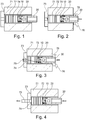
- Fig. 1
- is a longitudinal cross-sectional view through an extrusion press having a container with a lining, a die and a stem with a dummy block for pressing a billet in the container through the die.
- Fig. 2
- is a cross-sectional view similar to
fig 1 , where pressure is added to the billet and showing a plastic deformation of the billet in the front of the extrusion press, which forces remaining air backwards. - Fig. 3
- is a cross-sectional view similar to
fig 1 , where the billet is deformed by high pressure that starts the extrusion and now also touches the face of the filler ring in the dummy block, while air still escapes backwards. - Fig. 4
- is a cross-sectional view similar to
fig 1 , showing high axial pressure exerted on the ring, which forces the dummy block to expand radially due to conical contact surfaces so as to create a metal flashing free seal between the dummy block and the lining, while no air is left in the extrusion compartment. - Fig. 5
- is a longitudinal cross-sectional view through a front end body of a stem connected to a dummy block having a filler ring mounted in the body of the dummy block.
- Fig. 6
- is a longitudinal cross-sectional view of the components shown in
Fig. 5 separated from one another. - Fig. 7
- is a cross-sectional view of the dummy block body taken along the line VII-VII in
Fig. 8 . - Fig. 8
- is an end view of the dummy block body taken along line VIII-VIII in
Fig. 7 . - Fig. 9
- is a cross-sectional view of the filler ring taken along line IX-IX in
Fig. 10 . - Fig. 10
- is an end view of the filler ring taken along line X-X in
Fig. 9 . -
Figs. 1-4 illustrates the working principle of the dummy block of the present invention by showing a starting sequence of an extrusion. The shown extrusion press has acontainer 71 with alining 72, adie 73 and anextrusion stem 30 with adummy block 20 for pressing abillet 74 in thecontainer 71 through the die 73 to form anextruded profile 75. InFig. 1 , abillet 74 is placed in thecontainer 71, whichbillet 74 is pressed against the die 73 by a central portion of the dummy block 2. InFig. 2 , the pressure from theextrusion stem 30 on thebillet 74 is increased to cause a plastic deformation at the front of thebillet 74, which expands radially and also starts to enter thedie 73, so that air remaining in the extrusion compartment is forced backward to pass the dummy block 2 as there is no seal between the dummy block 2 and thelining 72. The escaping air is marked withreference numeral 76 inFigs. 2 and 3 . - The material of the billet is preferably metal, including steel, aluminum, copper, zirconium, titanium, molybdenum, beryllium, vanadium, or niobium.
The dummy block of the present invention is applicable primarily for hot extrusion, more preferably for metals at a temperature between 100 and 1300 °C. - In
Fig. 3 , the pressure from theextrusion stem 30 on thebillet 74 is increased even more, and thebillet 74 is deformed so that it now touches the face of afiller ring 10 included in the dummy block 2 and starts to press thering 10 down into agroove 40 located in a body of thedummy block 20. Air is still escaping backwards, but as thering 10 approaches the bottom 22 of thegroove 40, conical contact surfaces force an elastically deformable sealing lip 28 (Figs. 5, 6 and7 ) formed radially outside thegroove 40 in the dummy block 2 to expand radially so as to create a metal flashing free seal between the lining 72 and the dummy block 2 as illustrated inFig. 4 . Now, no air is left in extrusion compartment, extrusion commences without a burp cycle, and the extrudedprofile 75 is free from blisters. -
Figs. 5-10 show the invention more in detail. Theextrusion stem 30, or more specifically anadapter 31 carried by theextrusion stem 30, is connected to the dummy block 2 by means of a first connectingmember 32 of theadapter 31 mating with a second connecting member of the dummy block 2. The two connecting members suitably are a male member on theadapter 31 and a female member formed by a recess in the dummy block 2, and together they preferably form a bayonet coupling. However, if desired, any other suitable coupling may be used, e.g. threaded, pin locking system, etc. - The dummy block 2 comprises a
dummy block body 20 with arear face 201 adapted to be connected to theextrusion stem 30, and a front face provided with acircular groove 40 defining a centralpressing surface 21 for exerting a pressure on thebillet 74. Outside of thegroove 40, thedummy block body 20 has a peripheral annularpressing surface 281 for exerting a pressure on thebillet 74. The peripheral annularpressing surface 281 is located on said elastically deformable sealinglip 28 formed radially outside thegroove 40, and the sealinglip 28 is sufficiently elastically deformable to be pressed outward by the extrusion pressure to seal against an inside wall of the lining 72 in thecontainer 71. Thecircular groove 40 has a radiallyinner wall portion 23, a radiallyouter wall portion 24, and a bottom 22; theouter wall portion 24 is conical to make thegroove 40 open axially outward. - As indicated above, the dummy block 2 also comprises said
filler ring 10 adapted to fit in an upper part of thegroove 40 while forming agap 41 toward the bottom 22 of thegroove 40. Thering 10 has a conicalouter wall portion 14 complementary to the conicalouter wall portion 24 of thegroove 40. When thering 10 is being pressed toward the bottom 22 of thegroove 40, the elasticallydeformable sealing lip 28 will be forced radially outward to seal against the inside wall of the lining 72 in thecontainer 71. Accordingly, the elasticallydeformable sealing lip 28 will deform 0.05-4 mm, more preferably 0.1-3 mm, even more preferably 0.2-2 mm, most preferably 0.5-1 mm. - In accordance with the present invention also the
inner wall portion 23 of thegroove 40 is conical to make a cross-section of thegroove 40 substantially symmetrical, and thefiller ring 10 has an conicalinner wall portion 13 complementary to the conicalinner wall portion 23 of thegroove 40. - The dummy block 2 of the present invention consists of few components (only two, viz. the
dummy block body 20 and thefiller ring 10, apart from screws), and is of a very simple and axially compact design, reducing the required amount of structural material considerably. In addition, both of the groove sides 23 and 24 and both of the matchingsides filler ring 10 are conical, they converge toward the bottom 22 of thegroove 40. As the central pressingsurface 21 of thedummy block body 20 is rigid, thefiller ring 10 will expand radially when being pressed downward, and the sealinglip 28 will consequently be expanded radially both by the conical taper of the radial outside 14 of thering 10 and by the conical taper of the radial inside 13 of thefiller ring 10. As the cone angle of both of the groove sides 23 and 24 and both of the matchingsides filler ring 10 are sufficiently large to prevent thering 10 from getting stuck in thegroove 40, and as the sealinglip 28 is elastically deformable, after completed extrusion the sealinglip 28 will press back thefiller ring 10 and resume its original shape, so that the dummy block 2 is reusable. - Preferably, the central pressing
surface 21 is located in afirst plane 80, the peripheral annularpressing surface 281 on the sealinglip 28 is located in asecond plane 81 parallel to the first plane but closer to therear face 201 of thedummy block body 20, and as best shown inFig. 5 thefiller ring 10 has apressing surface 11 located in a position between said first andsecond planes surface 21 of thedummy block body 20 will start deforming thebillet 74 by reducing its length but increasing its diameter, so that the air surrounding thebillet 74 in thecontainer 71 will be pressed backward through the peripheral gap between the inside wall of the lining 72 in thecontainer 71 and sealinglip 28 formed radially outside thegroove 40 and further past the dummy block 2 and theextrusion stem 30 to reduce the risk of blisters in the extrudedprofile 75 discharged from the extrusion press. - As shown in
Fig. 5 , it is preferred that thepressing surface 11 of thefiller ring 10 is located in athird plane 82 parallel to the twoother planes deformed billet 74 abuts thepressing surface 11 of thefiller ring 10 and thepressing surface 281 of said sealinglip 28. As soon as the pressure from thebillet 74 on thefiller ring 10 is sufficiently high, it presses thefiller ring 10 downward into thegroove 40, thereby causing said sealinglip 28 radially outside the groove to elastically expand radially to seal against the inside wall of the lining 72 in thecontainer 71, whilegap 41 decreases to 0 mm. This design results in a stepwise sealing effect which makes it possible for all air to come out during the compression and gives a fix and reproducible radial expansion of sealinglip 28. As no air is left in extrusion compartment, extrusion commences without a burp cycle, and the extrudedprofile 75 is free from blisters. - In the embodiment shown in the drawings, the lower portion of the groove sides 23 and 24 and also the lower portion of the matching
sides filler ring 10 are not conical but cylindrical and extend parallel to a longitudinal axis of the dummy block 2. In thefiller ring 10, the length of the cylindrical portion and the height of the conical portion are of substantially the same size, while in thegroove 40 the length of the cylindrical portion is slightly longer than the height of the conical portion. Thereby thepressing surface 11 of thefiller ring 10 will be located in thethird plane 82 and thepressing surface 281 of the sealinglip 28 in thesecond plane 81. Further, thegap 41 will be formed between thebottom surface 12 of thefiller ring 10 and the bottom 22 of thegroove 40. This design of thefiller ring 10 and thegroove 40 will prevent any possible tendency of skewing of thefiller ring 10 in thegroove 40 caused by uneven counter forces from thebillet 74 during the extrusion. - Suitably, the
rear face 201 of thedummy block body 20 is provided with at least one stepped through bore 25 opening in the bottom 22 of thegroove 40, thefiller ring 10 has abottom surface 12 provided with at least one threaded bore 15 aligned with the stepped throughbore 25 of thedummy block body 20, and ascrew 50 extends through the stepped bore 25 into the threaded bore 15 to anchor thefiller ring 10 in thegroove 40. Thereby, thefiller ring 10 is prevented from falling out of thegroove 40 when handling the dummy block 2 outside of thecontainer 71. - To improve the safety against a skew mounting of the
filler ring 10 in thegroove 40, it is suitable that both thedummy block body 20 and thefiller ring 10 have two or moresuch bores - When the
filler ring 10 is being pressed down in thegroove 40, the air enclosed in thegap 41 formed between thebottom surface 12 of thering 10 and the bottom 22 of thegroove 40 will be compressed. To make sure that all compressed air will be removed, it is suitable that a ventingchannel 251 is provided for permitting air to escape from the bottom 22 of thegroove 40 through the stepped bore 25 and between theextrusion stem 30 and therear face 201 of thedummy block body 20 and out to a space radially outside theextrusion stem 30. - The
dummy block body 20 preferably has afemale receptor 27 of a bayonet mount for receiving amating male portion 32 on theextrusion stem 30. Thereby the dummy block 2 can be made short and compact. - The
female receptor 27 of the bayonet mount suitably has two or more equiangularly spacedinternal cams 271 for cooperation with two or more equiangularly spacedexternal cams 33 on the male portion of theextrusion stem 30. - It is preferred that the
rear face 201 of thedummy block body 20 has at least one threaded bore 26 located close to an outer circumference thereof, and theextrusion stem 30 has a correspondingly placed slot-shapedrecess 36 that permits insertion and tightening of amachine screw 60 having a head that prevents an involuntary uncoupling of the bayonet mount by being stopped by sides of the slot-shapedrecess 36. Further, it is recommendable that therear face 201 of thedummy block body 20 has two or more such threadedbores 26 that are equiangularly spaced and theextrusion stem 30 has two or more such slot-shapedrecesses 36 that are equiangularly spaced. - It is also preferred that the elastically
deformable sealing lip 28 formed radially outside thegroove 40 is stepped in its longitudinal direction and has a larger diameter at saidfront face 281 than at saidrear face 201, thereby forming a sealingsurface 29 for sealing against an inside wall of thecontainer lining 72. - The scope of the present invention is not restricted to the preferred embodiment shown in the drawings and described in the specification but can be varied without departing from the scope of the appended claims. As an example, if desired, it would be possible without any inventive activity to employ a bayonet mount between the
ring 10 and thedummy block body 20. Another example is the material used for extrusion, which is preferably a metal, but can as well be a non-metal based material, as composite or other material. The construction ofring 10 can for example be other than circular, e.g. rectangular, etc. - The dummy block of the present invention is applicable primarily for hot extrusion of metals in both front and back loaded extrusion presses, but can be used also for cold extrusion.
Claims (12)
- A dummy block (2) for an extrusion press having a die (73), a container (71) for receiving a billet (74) to be extruded through the die (73), and an extrusion stem (30) for exerting a pressure on the billet (74) sufficient to extrude it through the die (73), said dummy block (2) being, in use, positioned between the extrusion stem (30) and the billet (74) and comprising:a dummy block body (20) having a rear face (201) adapted to be connected to the extrusion stem (30), and a front face provided with a groove (40) defining a pressing surface (21) for exerting a pressure on the billet (74), and outside of the groove (40) a peripheral pressing surface (281) for exerting a pressure on the billet (74), a sealing lip (28) formed radially outside the groove (40), said groove (40) having an inner wall portion (23), an outer wall portion (24), and a bottom (22), said outer wall portion (24) being conical to make the groove (40) open outward; anda filler ring (10) adapted to fit in an upper part of the groove (40) while forming a gap (41) toward the bottom (22) of the groove (40), said ring (10) having a conical outer wall portion (14) complementary to the conical outer wall portion (24) of the groove (40), said ring (10), when being pressed toward the bottom (22) of the groove (40), forcing said sealing lip (28) outward to seal against the inside lining (72) of the container (71);
characterized bysaid inner wall portion (23) of the groove (40) being conical to make a cross-section of the groove (40) substantially symmetrical; and said filler ring (10) having a conical inner wall portion (13) complementary to the conical inner wall portion (23) of the groove (40). - A dummy block according to claim 1, wherein the sealing lip (28) is being sufficiently elastically deformable to be pressed outward by the extrusion pressure to seal against the inside lining (72) of the container (71).
- A dummy block according to claim 1 or 2, wherein the central pressing surface (21) is located in a first plane (80), the peripheral annular pressing surface (281) is located in a second plane (81) parallel to the first plane but closer to the rear face (201) of the dummy block body (20), and the filler ring (10) has a pressing surface (11) located in a position between said first and second plane (80, 81).
- A dummy block according to any one of claims 1 to 3, wherein the pressing surface (11) of the filler ring (10) is located in a third plane (82) parallel to the two other planes (80, 81).
- A dummy block according to any one of claims 1-4, wherein the rear face (201) of the dummy block body (20) is provided with at least one stepped through bore (25) opening in the bottom (22) of the groove (40), the filler ring (10) has a bottom surface (12) provided with at least one threaded bore (15) aligned with the stepped through bore (25) of the dummy block body (20), and a screw (50) extends through the stepped bore (25) into the threaded bore (15) to anchor the filler ring (10) in the groove (40).
- A dummy block according to claim 5, wherein both the dummy block body (20) and the filler ring (10) has two or more such bores (25; 15), which are equiangularly spaced from each other.
- A dummy block according to claim 5 or 6, wherein a venting channel (251) is provided for permitting air to escape from the bottom (22) of the groove (40) through the stepped bore (25) and between the extrusion stem (30) and the rear face (201) of the dummy block body (20) and out to a space radially outside the extrusion stem (30).
- A dummy block according to any one of claims 1-7, wherein the dummy block body (20) has a female receptor of a bayonet mount, for receiving a mating male portion (32) on the extrusion stem (30).
- A dummy block according to claim 8, wherein the female receptor of a bayonet mount has two or more equiangularly spaced internal cams (27) for cooperation with two or more equiangularly spaced external cams (33) on the male portion (32) of the extrusion stem (30).
- A dummy block according to claim 8 or 9, wherein the rear face (201) of the dummy block body (20) has at least one threaded bore (26) located close to an outer circumference thereof, and the extrusion stem (30) has a slot-shaped recess (36) placed correspondingly to said at least one threaded bore (26), the recess (36) permitting insertion and tightening of a machine screw (60) having a head that prevents an involuntary uncoupling of the bayonet mount by being stopped by sides of the slot-shaped recess (36).
- A dummy block according to claim 10, wherein the rear face (201) of the dummy block body (20) has two or more such threaded bores (26) that are equiangularly spaced and the extrusion stem (30) has two or more such slot-shaped recesses (36) that are equiangularly spaced.
- A dummy block according to any one of claims 1-11, wherein the elastically deformable sealing lip (28) formed radially outside the groove (40) is stepped in its longitudinal direction and has a larger diameter at said front face (281) than at said rear face (201).
Priority Applications (3)
| Application Number | Priority Date | Filing Date | Title |
|---|---|---|---|
| PL15173525T PL3108979T3 (en) | 2015-06-24 | 2015-06-24 | A dummy block for an extrusion press |
| EP15173525.5A EP3108979B1 (en) | 2015-06-24 | 2015-06-24 | A dummy block for an extrusion press |
| PCT/EP2016/064379 WO2016207198A1 (en) | 2015-06-24 | 2016-06-22 | A dummy block for an extrusion press |
Applications Claiming Priority (1)
| Application Number | Priority Date | Filing Date | Title |
|---|---|---|---|
| EP15173525.5A EP3108979B1 (en) | 2015-06-24 | 2015-06-24 | A dummy block for an extrusion press |
Publications (2)
| Publication Number | Publication Date |
|---|---|
| EP3108979A1 EP3108979A1 (en) | 2016-12-28 |
| EP3108979B1 true EP3108979B1 (en) | 2017-08-09 |
Family
ID=53496466
Family Applications (1)
| Application Number | Title | Priority Date | Filing Date |
|---|---|---|---|
| EP15173525.5A Active EP3108979B1 (en) | 2015-06-24 | 2015-06-24 | A dummy block for an extrusion press |
Country Status (3)
| Country | Link |
|---|---|
| EP (1) | EP3108979B1 (en) |
| PL (1) | PL3108979T3 (en) |
| WO (1) | WO2016207198A1 (en) |
Families Citing this family (6)
| Publication number | Priority date | Publication date | Assignee | Title |
|---|---|---|---|---|
| CN113226582A (en) * | 2018-11-15 | 2021-08-06 | 美国密歇根州立大学董事会 | Extruding metal material using extrusion pad having curved surface |
| CN109968628B (en) * | 2019-04-11 | 2024-04-16 | 昌乐友谊塑胶科技股份有限公司 | Double-layer co-extrusion die for rubber and plastic pipe |
| CN110961479B (en) * | 2019-11-18 | 2021-07-16 | 太重(天津)滨海重型机械有限公司 | Self-expanding die for reverse extruder and method of assembling same |
| CN112775203B (en) * | 2020-12-23 | 2024-01-19 | 西部新锆核材料科技有限公司 | Preparation method of zirconium or zirconium alloy extrusion profile |
| CN116197293B (en) * | 2023-04-27 | 2023-07-21 | 中北大学 | Back extrusion preparation die and method for inner and outer bimetal cup-shaped components |
| CN117505572A (en) * | 2024-01-08 | 2024-02-06 | 中国重型机械研究院股份公司 | Tool and die structure for producing seamless pipe by single-action extruder and extrusion method |
Family Cites Families (4)
| Publication number | Priority date | Publication date | Assignee | Title |
|---|---|---|---|---|
| DE20022762U1 (en) * | 2000-07-25 | 2002-05-08 | Binger Anna Dora | Fixed press washer |
| AU2002316803A1 (en) * | 2002-05-29 | 2003-12-12 | Alex-Tech Aps | Dummy block for an extrusion press |
| DE102010064400B4 (en) | 2010-12-01 | 2012-09-20 | Horst Heydasch | Press disc and pressing device with such a pressure washer |
| CN202155388U (en) * | 2011-06-15 | 2012-03-07 | 亚太轻合金(南通)科技有限公司 | Diameter-adjustable fixed extruding pad of novel aluminum profile extruding machine |
-
2015
- 2015-06-24 EP EP15173525.5A patent/EP3108979B1/en active Active
- 2015-06-24 PL PL15173525T patent/PL3108979T3/en unknown
-
2016
- 2016-06-22 WO PCT/EP2016/064379 patent/WO2016207198A1/en active Application Filing
Non-Patent Citations (1)
| Title |
|---|
| None * |
Also Published As
| Publication number | Publication date |
|---|---|
| PL3108979T3 (en) | 2018-01-31 |
| WO2016207198A1 (en) | 2016-12-29 |
| EP3108979A1 (en) | 2016-12-28 |
Similar Documents
| Publication | Publication Date | Title |
|---|---|---|
| EP3108979B1 (en) | A dummy block for an extrusion press | |
| US5349840A (en) | Method of making a high torque battery terminal | |
| CN104819196A (en) | Fastener and fastening system | |
| US5954116A (en) | Shot sleeve and shot unit for a die casting machine | |
| US9839950B2 (en) | Dummy block for extrusion press | |
| CN106102950B (en) | The device for deforming workpiece for the molding die of workpiece and with the mold | |
| CN106862559B (en) | For carrying out the method and mold of surface densification and calibration to sintered component | |
| US2925176A (en) | Dummy head or block for end of extrusion ram | |
| CN105312349A (en) | Method of increasing deformation quantity of cylinder bottom of metal backward-extrusion cylindrical part | |
| EP3057726B1 (en) | Wear ring for die-casting piston, die-casting piston incorporating same, and method of forming same | |
| GB2067944A (en) | Extrusion process | |
| CN103537507B (en) | A kind of hollow outward flange part mold for extruding and forming and punch thereof | |
| CN111421012A (en) | Extrusion tool for metal processing | |
| JP5102017B2 (en) | Extrusion die and extruded material manufacturing method | |
| JP2000343171A (en) | Forward extrusion forging method | |
| CN105945193A (en) | Bearing support body forging die | |
| CN113664088A (en) | Plunger piston shoe closing-in tool | |
| RU2451569C2 (en) | Method of mass extruding of barrel-type parts by angular extrusion at horizontal hydraulic extruder | |
| CN212551069U (en) | Extrusion tool for metal processing | |
| RU2611634C2 (en) | Piercer for compression blanks | |
| CN114054660B (en) | Combined die for cold heading capped rod piece | |
| WO2017075714A1 (en) | Dummy block for extrusion press | |
| RU2134622C1 (en) | Hollow product pressing tool | |
| CN103128124B (en) | Aluminium extruding machine flexible fastening dummy block method for designing | |
| Design | The Critical Interaction of the Dummy Block and Container in Modern Extrusion Presses |
Legal Events
| Date | Code | Title | Description |
|---|---|---|---|
| PUAI | Public reference made under article 153(3) epc to a published international application that has entered the european phase |
Free format text: ORIGINAL CODE: 0009012 |
|
| 17P | Request for examination filed |
Effective date: 20160202 |
|
| AK | Designated contracting states |
Kind code of ref document: A1 Designated state(s): AL AT BE BG CH CY CZ DE DK EE ES FI FR GB GR HR HU IE IS IT LI LT LU LV MC MK MT NL NO PL PT RO RS SE SI SK SM TR |
|
| AX | Request for extension of the european patent |
Extension state: BA ME |
|
| GRAP | Despatch of communication of intention to grant a patent |
Free format text: ORIGINAL CODE: EPIDOSNIGR1 |
|
| INTG | Intention to grant announced |
Effective date: 20170404 |
|
| GRAS | Grant fee paid |
Free format text: ORIGINAL CODE: EPIDOSNIGR3 |
|
| GRAA | (expected) grant |
Free format text: ORIGINAL CODE: 0009210 |
|
| AK | Designated contracting states |
Kind code of ref document: B1 Designated state(s): AL AT BE BG CH CY CZ DE DK EE ES FI FR GB GR HR HU IE IS IT LI LT LU LV MC MK MT NL NO PL PT RO RS SE SI SK SM TR |
|
| REG | Reference to a national code |
Ref country code: GB Ref legal event code: FG4D |
|
| REG | Reference to a national code |
Ref country code: CH Ref legal event code: EP Ref country code: AT Ref legal event code: REF Ref document number: 916256 Country of ref document: AT Kind code of ref document: T Effective date: 20170815 |
|
| REG | Reference to a national code |
Ref country code: IE Ref legal event code: FG4D |
|
| REG | Reference to a national code |
Ref country code: DE Ref legal event code: R096 Ref document number: 602015003977 Country of ref document: DE |
|
| REG | Reference to a national code |
Ref country code: NL Ref legal event code: FP |
|
| REG | Reference to a national code |
Ref country code: SE Ref legal event code: TRGR |
|
| REG | Reference to a national code |
Ref country code: LT Ref legal event code: MG4D |
|
| REG | Reference to a national code |
Ref country code: AT Ref legal event code: MK05 Ref document number: 916256 Country of ref document: AT Kind code of ref document: T Effective date: 20170809 |
|
| PG25 | Lapsed in a contracting state [announced via postgrant information from national office to epo] |
Ref country code: HR Free format text: LAPSE BECAUSE OF FAILURE TO SUBMIT A TRANSLATION OF THE DESCRIPTION OR TO PAY THE FEE WITHIN THE PRESCRIBED TIME-LIMIT Effective date: 20170809 Ref country code: AT Free format text: LAPSE BECAUSE OF FAILURE TO SUBMIT A TRANSLATION OF THE DESCRIPTION OR TO PAY THE FEE WITHIN THE PRESCRIBED TIME-LIMIT Effective date: 20170809 Ref country code: NO Free format text: LAPSE BECAUSE OF FAILURE TO SUBMIT A TRANSLATION OF THE DESCRIPTION OR TO PAY THE FEE WITHIN THE PRESCRIBED TIME-LIMIT Effective date: 20171109 Ref country code: LT Free format text: LAPSE BECAUSE OF FAILURE TO SUBMIT A TRANSLATION OF THE DESCRIPTION OR TO PAY THE FEE WITHIN THE PRESCRIBED TIME-LIMIT Effective date: 20170809 |
|
| PG25 | Lapsed in a contracting state [announced via postgrant information from national office to epo] |
Ref country code: LV Free format text: LAPSE BECAUSE OF FAILURE TO SUBMIT A TRANSLATION OF THE DESCRIPTION OR TO PAY THE FEE WITHIN THE PRESCRIBED TIME-LIMIT Effective date: 20170809 Ref country code: GR Free format text: LAPSE BECAUSE OF FAILURE TO SUBMIT A TRANSLATION OF THE DESCRIPTION OR TO PAY THE FEE WITHIN THE PRESCRIBED TIME-LIMIT Effective date: 20171110 Ref country code: ES Free format text: LAPSE BECAUSE OF FAILURE TO SUBMIT A TRANSLATION OF THE DESCRIPTION OR TO PAY THE FEE WITHIN THE PRESCRIBED TIME-LIMIT Effective date: 20170809 Ref country code: RS Free format text: LAPSE BECAUSE OF FAILURE TO SUBMIT A TRANSLATION OF THE DESCRIPTION OR TO PAY THE FEE WITHIN THE PRESCRIBED TIME-LIMIT Effective date: 20170809 Ref country code: BG Free format text: LAPSE BECAUSE OF FAILURE TO SUBMIT A TRANSLATION OF THE DESCRIPTION OR TO PAY THE FEE WITHIN THE PRESCRIBED TIME-LIMIT Effective date: 20171109 Ref country code: IS Free format text: LAPSE BECAUSE OF FAILURE TO SUBMIT A TRANSLATION OF THE DESCRIPTION OR TO PAY THE FEE WITHIN THE PRESCRIBED TIME-LIMIT Effective date: 20171209 |
|
| REG | Reference to a national code |
Ref country code: DE Ref legal event code: R081 Ref document number: 602015003977 Country of ref document: DE Owner name: VOESTALPINE HIGH PERFORMANCE METALS SWEDEN AB, SE Free format text: FORMER OWNER: UDDEHOLM SVENSKA AB, MOELNDAL, SE |
|
| RAP2 | Party data changed (patent owner data changed or rights of a patent transferred) |
Owner name: VOESTALPINE HIGH PERFORMANCE METALS SWEDEN AB |
|
| PG25 | Lapsed in a contracting state [announced via postgrant information from national office to epo] |
Ref country code: DK Free format text: LAPSE BECAUSE OF FAILURE TO SUBMIT A TRANSLATION OF THE DESCRIPTION OR TO PAY THE FEE WITHIN THE PRESCRIBED TIME-LIMIT Effective date: 20170809 Ref country code: CZ Free format text: LAPSE BECAUSE OF FAILURE TO SUBMIT A TRANSLATION OF THE DESCRIPTION OR TO PAY THE FEE WITHIN THE PRESCRIBED TIME-LIMIT Effective date: 20170809 |
|
| REG | Reference to a national code |
Ref country code: NL Ref legal event code: HC Owner name: VOESTALPINE HIGH PERFORMANCE METALS SWEDEN AB.; SE Free format text: DETAILS ASSIGNMENT: CHANGE OF OWNER(S), CHANGE OF OWNER(S) NAME; FORMER OWNER NAME: UDDEHOLM SVENSKA AB Effective date: 20180309 |
|
| REG | Reference to a national code |
Ref country code: DE Ref legal event code: R097 Ref document number: 602015003977 Country of ref document: DE |
|
| PG25 | Lapsed in a contracting state [announced via postgrant information from national office to epo] |
Ref country code: EE Free format text: LAPSE BECAUSE OF FAILURE TO SUBMIT A TRANSLATION OF THE DESCRIPTION OR TO PAY THE FEE WITHIN THE PRESCRIBED TIME-LIMIT Effective date: 20170809 Ref country code: SM Free format text: LAPSE BECAUSE OF FAILURE TO SUBMIT A TRANSLATION OF THE DESCRIPTION OR TO PAY THE FEE WITHIN THE PRESCRIBED TIME-LIMIT Effective date: 20170809 Ref country code: SK Free format text: LAPSE BECAUSE OF FAILURE TO SUBMIT A TRANSLATION OF THE DESCRIPTION OR TO PAY THE FEE WITHIN THE PRESCRIBED TIME-LIMIT Effective date: 20170809 |
|
| PLBE | No opposition filed within time limit |
Free format text: ORIGINAL CODE: 0009261 |
|
| REG | Reference to a national code |
Ref country code: FR Ref legal event code: PLFP Year of fee payment: 4 |
|
| STAA | Information on the status of an ep patent application or granted ep patent |
Free format text: STATUS: NO OPPOSITION FILED WITHIN TIME LIMIT |
|
| REG | Reference to a national code |
Ref country code: BE Ref legal event code: HC Owner name: VOESTALPINE HIGH PERFORMANCE METALS SWEDEN AB; SE Free format text: DETAILS ASSIGNMENT: CHANGE OF OWNER(S), CHANGEMENT DE NOM DU PROPRIETAIRE; FORMER OWNER NAME: UDDEHOLM SVENSKA AB Effective date: 20180308 |
|
| 26N | No opposition filed |
Effective date: 20180511 |
|
| PG25 | Lapsed in a contracting state [announced via postgrant information from national office to epo] |
Ref country code: SI Free format text: LAPSE BECAUSE OF FAILURE TO SUBMIT A TRANSLATION OF THE DESCRIPTION OR TO PAY THE FEE WITHIN THE PRESCRIBED TIME-LIMIT Effective date: 20170809 |
|
| REG | Reference to a national code |
Ref country code: CH Ref legal event code: PL |
|
| REG | Reference to a national code |
Ref country code: IE Ref legal event code: MM4A |
|
| PG25 | Lapsed in a contracting state [announced via postgrant information from national office to epo] |
Ref country code: MC Free format text: LAPSE BECAUSE OF FAILURE TO SUBMIT A TRANSLATION OF THE DESCRIPTION OR TO PAY THE FEE WITHIN THE PRESCRIBED TIME-LIMIT Effective date: 20170809 Ref country code: LU Free format text: LAPSE BECAUSE OF NON-PAYMENT OF DUE FEES Effective date: 20180624 |
|
| PG25 | Lapsed in a contracting state [announced via postgrant information from national office to epo] |
Ref country code: IE Free format text: LAPSE BECAUSE OF NON-PAYMENT OF DUE FEES Effective date: 20180624 Ref country code: LI Free format text: LAPSE BECAUSE OF NON-PAYMENT OF DUE FEES Effective date: 20180630 Ref country code: CH Free format text: LAPSE BECAUSE OF NON-PAYMENT OF DUE FEES Effective date: 20180630 |
|
| PG25 | Lapsed in a contracting state [announced via postgrant information from national office to epo] |
Ref country code: MT Free format text: LAPSE BECAUSE OF NON-PAYMENT OF DUE FEES Effective date: 20180624 |
|
| GBPC | Gb: european patent ceased through non-payment of renewal fee |
Effective date: 20190624 |
|
| PG25 | Lapsed in a contracting state [announced via postgrant information from national office to epo] |
Ref country code: TR Free format text: LAPSE BECAUSE OF FAILURE TO SUBMIT A TRANSLATION OF THE DESCRIPTION OR TO PAY THE FEE WITHIN THE PRESCRIBED TIME-LIMIT Effective date: 20170809 |
|
| PG25 | Lapsed in a contracting state [announced via postgrant information from national office to epo] |
Ref country code: GB Free format text: LAPSE BECAUSE OF NON-PAYMENT OF DUE FEES Effective date: 20190624 |
|
| PG25 | Lapsed in a contracting state [announced via postgrant information from national office to epo] |
Ref country code: PT Free format text: LAPSE BECAUSE OF FAILURE TO SUBMIT A TRANSLATION OF THE DESCRIPTION OR TO PAY THE FEE WITHIN THE PRESCRIBED TIME-LIMIT Effective date: 20170809 |
|
| PG25 | Lapsed in a contracting state [announced via postgrant information from national office to epo] |
Ref country code: CY Free format text: LAPSE BECAUSE OF FAILURE TO SUBMIT A TRANSLATION OF THE DESCRIPTION OR TO PAY THE FEE WITHIN THE PRESCRIBED TIME-LIMIT Effective date: 20170809 Ref country code: HU Free format text: LAPSE BECAUSE OF FAILURE TO SUBMIT A TRANSLATION OF THE DESCRIPTION OR TO PAY THE FEE WITHIN THE PRESCRIBED TIME-LIMIT; INVALID AB INITIO Effective date: 20150624 Ref country code: MK Free format text: LAPSE BECAUSE OF NON-PAYMENT OF DUE FEES Effective date: 20170809 Ref country code: RO Free format text: LAPSE BECAUSE OF FAILURE TO SUBMIT A TRANSLATION OF THE DESCRIPTION OR TO PAY THE FEE WITHIN THE PRESCRIBED TIME-LIMIT Effective date: 20170809 |
|
| PG25 | Lapsed in a contracting state [announced via postgrant information from national office to epo] |
Ref country code: AL Free format text: LAPSE BECAUSE OF FAILURE TO SUBMIT A TRANSLATION OF THE DESCRIPTION OR TO PAY THE FEE WITHIN THE PRESCRIBED TIME-LIMIT Effective date: 20170809 |
|
| PGFP | Annual fee paid to national office [announced via postgrant information from national office to epo] |
Ref country code: SE Payment date: 20220623 Year of fee payment: 8 Ref country code: NL Payment date: 20220630 Year of fee payment: 8 Ref country code: IT Payment date: 20220620 Year of fee payment: 8 Ref country code: DE Payment date: 20220621 Year of fee payment: 8 |
|
| PGFP | Annual fee paid to national office [announced via postgrant information from national office to epo] |
Ref country code: PL Payment date: 20220524 Year of fee payment: 8 Ref country code: FI Payment date: 20220621 Year of fee payment: 8 Ref country code: BE Payment date: 20220613 Year of fee payment: 8 |
|
| PGFP | Annual fee paid to national office [announced via postgrant information from national office to epo] |
Ref country code: FR Payment date: 20220614 Year of fee payment: 8 |
|
| REG | Reference to a national code |
Ref country code: DE Ref legal event code: R119 Ref document number: 602015003977 Country of ref document: DE |
|
| REG | Reference to a national code |
Ref country code: SE Ref legal event code: EUG |
|
| PG25 | Lapsed in a contracting state [announced via postgrant information from national office to epo] |
Ref country code: FI Free format text: LAPSE BECAUSE OF NON-PAYMENT OF DUE FEES Effective date: 20230624 |
|
| REG | Reference to a national code |
Ref country code: NL Ref legal event code: MM Effective date: 20230701 |
|
| REG | Reference to a national code |
Ref country code: BE Ref legal event code: MM Effective date: 20230630 |
|
| PG25 | Lapsed in a contracting state [announced via postgrant information from national office to epo] |
Ref country code: NL Free format text: LAPSE BECAUSE OF NON-PAYMENT OF DUE FEES Effective date: 20230701 |
|
| PG25 | Lapsed in a contracting state [announced via postgrant information from national office to epo] |
Ref country code: DE Free format text: LAPSE BECAUSE OF NON-PAYMENT OF DUE FEES Effective date: 20240103 |