EP3108795B1 - Endoscope system and endoscope control process - Google Patents
Endoscope system and endoscope control process Download PDFInfo
- Publication number
- EP3108795B1 EP3108795B1 EP15751956.2A EP15751956A EP3108795B1 EP 3108795 B1 EP3108795 B1 EP 3108795B1 EP 15751956 A EP15751956 A EP 15751956A EP 3108795 B1 EP3108795 B1 EP 3108795B1
- Authority
- EP
- European Patent Office
- Prior art keywords
- unit
- image
- amount
- endoscope
- driving
- Prior art date
- Legal status (The legal status is an assumption and is not a legal conclusion. Google has not performed a legal analysis and makes no representation as to the accuracy of the status listed.)
- Active
Links
Images


Classifications
-
- A—HUMAN NECESSITIES
- A61—MEDICAL OR VETERINARY SCIENCE; HYGIENE
- A61B—DIAGNOSIS; SURGERY; IDENTIFICATION
- A61B1/00—Instruments for performing medical examinations of the interior of cavities or tubes of the body by visual or photographical inspection, e.g. endoscopes; Illuminating arrangements therefor
- A61B1/00002—Operational features of endoscopes
- A61B1/00004—Operational features of endoscopes characterised by electronic signal processing
- A61B1/00006—Operational features of endoscopes characterised by electronic signal processing of control signals
-
- A—HUMAN NECESSITIES
- A61—MEDICAL OR VETERINARY SCIENCE; HYGIENE
- A61B—DIAGNOSIS; SURGERY; IDENTIFICATION
- A61B1/00—Instruments for performing medical examinations of the interior of cavities or tubes of the body by visual or photographical inspection, e.g. endoscopes; Illuminating arrangements therefor
- A61B1/00002—Operational features of endoscopes
- A61B1/00004—Operational features of endoscopes characterised by electronic signal processing
- A61B1/00009—Operational features of endoscopes characterised by electronic signal processing of image signals during a use of endoscope
-
- A—HUMAN NECESSITIES
- A61—MEDICAL OR VETERINARY SCIENCE; HYGIENE
- A61B—DIAGNOSIS; SURGERY; IDENTIFICATION
- A61B1/00—Instruments for performing medical examinations of the interior of cavities or tubes of the body by visual or photographical inspection, e.g. endoscopes; Illuminating arrangements therefor
- A61B1/00002—Operational features of endoscopes
- A61B1/00039—Operational features of endoscopes provided with input arrangements for the user
- A61B1/00042—Operational features of endoscopes provided with input arrangements for the user for mechanical operation
-
- A—HUMAN NECESSITIES
- A61—MEDICAL OR VETERINARY SCIENCE; HYGIENE
- A61B—DIAGNOSIS; SURGERY; IDENTIFICATION
- A61B1/00—Instruments for performing medical examinations of the interior of cavities or tubes of the body by visual or photographical inspection, e.g. endoscopes; Illuminating arrangements therefor
- A61B1/00002—Operational features of endoscopes
- A61B1/00043—Operational features of endoscopes provided with output arrangements
- A61B1/00045—Display arrangement
-
- A—HUMAN NECESSITIES
- A61—MEDICAL OR VETERINARY SCIENCE; HYGIENE
- A61B—DIAGNOSIS; SURGERY; IDENTIFICATION
- A61B1/00—Instruments for performing medical examinations of the interior of cavities or tubes of the body by visual or photographical inspection, e.g. endoscopes; Illuminating arrangements therefor
- A61B1/00147—Holding or positioning arrangements
- A61B1/00149—Holding or positioning arrangements using articulated arms
-
- A—HUMAN NECESSITIES
- A61—MEDICAL OR VETERINARY SCIENCE; HYGIENE
- A61B—DIAGNOSIS; SURGERY; IDENTIFICATION
- A61B1/00—Instruments for performing medical examinations of the interior of cavities or tubes of the body by visual or photographical inspection, e.g. endoscopes; Illuminating arrangements therefor
- A61B1/00147—Holding or positioning arrangements
- A61B1/00154—Holding or positioning arrangements using guiding arrangements for insertion
-
- A—HUMAN NECESSITIES
- A61—MEDICAL OR VETERINARY SCIENCE; HYGIENE
- A61B—DIAGNOSIS; SURGERY; IDENTIFICATION
- A61B1/00—Instruments for performing medical examinations of the interior of cavities or tubes of the body by visual or photographical inspection, e.g. endoscopes; Illuminating arrangements therefor
- A61B1/00147—Holding or positioning arrangements
- A61B1/0016—Holding or positioning arrangements using motor drive units
-
- A—HUMAN NECESSITIES
- A61—MEDICAL OR VETERINARY SCIENCE; HYGIENE
- A61B—DIAGNOSIS; SURGERY; IDENTIFICATION
- A61B1/00—Instruments for performing medical examinations of the interior of cavities or tubes of the body by visual or photographical inspection, e.g. endoscopes; Illuminating arrangements therefor
- A61B1/00163—Optical arrangements
- A61B1/00172—Optical arrangements with means for scanning
-
- A—HUMAN NECESSITIES
- A61—MEDICAL OR VETERINARY SCIENCE; HYGIENE
- A61B—DIAGNOSIS; SURGERY; IDENTIFICATION
- A61B1/00—Instruments for performing medical examinations of the interior of cavities or tubes of the body by visual or photographical inspection, e.g. endoscopes; Illuminating arrangements therefor
- A61B1/00163—Optical arrangements
- A61B1/00174—Optical arrangements characterised by the viewing angles
- A61B1/00183—Optical arrangements characterised by the viewing angles for variable viewing angles
-
- A—HUMAN NECESSITIES
- A61—MEDICAL OR VETERINARY SCIENCE; HYGIENE
- A61B—DIAGNOSIS; SURGERY; IDENTIFICATION
- A61B1/00—Instruments for performing medical examinations of the interior of cavities or tubes of the body by visual or photographical inspection, e.g. endoscopes; Illuminating arrangements therefor
- A61B1/04—Instruments for performing medical examinations of the interior of cavities or tubes of the body by visual or photographical inspection, e.g. endoscopes; Illuminating arrangements therefor combined with photographic or television appliances
- A61B1/045—Control thereof
-
- A—HUMAN NECESSITIES
- A61—MEDICAL OR VETERINARY SCIENCE; HYGIENE
- A61B—DIAGNOSIS; SURGERY; IDENTIFICATION
- A61B1/00—Instruments for performing medical examinations of the interior of cavities or tubes of the body by visual or photographical inspection, e.g. endoscopes; Illuminating arrangements therefor
- A61B1/313—Instruments for performing medical examinations of the interior of cavities or tubes of the body by visual or photographical inspection, e.g. endoscopes; Illuminating arrangements therefor for introducing through surgical openings, e.g. laparoscopes
- A61B1/3132—Instruments for performing medical examinations of the interior of cavities or tubes of the body by visual or photographical inspection, e.g. endoscopes; Illuminating arrangements therefor for introducing through surgical openings, e.g. laparoscopes for laparoscopy
-
- A—HUMAN NECESSITIES
- A61—MEDICAL OR VETERINARY SCIENCE; HYGIENE
- A61B—DIAGNOSIS; SURGERY; IDENTIFICATION
- A61B17/00—Surgical instruments, devices or methods, e.g. tourniquets
- A61B17/00234—Surgical instruments, devices or methods, e.g. tourniquets for minimally invasive surgery
-
- A—HUMAN NECESSITIES
- A61—MEDICAL OR VETERINARY SCIENCE; HYGIENE
- A61B—DIAGNOSIS; SURGERY; IDENTIFICATION
- A61B5/00—Measuring for diagnostic purposes; Identification of persons
- A61B5/06—Devices, other than using radiation, for detecting or locating foreign bodies ; determining position of probes within or on the body of the patient
- A61B5/065—Determining position of the probe employing exclusively positioning means located on or in the probe, e.g. using position sensors arranged on the probe
-
- G—PHYSICS
- G02—OPTICS
- G02B—OPTICAL ELEMENTS, SYSTEMS OR APPARATUS
- G02B23/00—Telescopes, e.g. binoculars; Periscopes; Instruments for viewing the inside of hollow bodies; Viewfinders; Optical aiming or sighting devices
- G02B23/24—Instruments or systems for viewing the inside of hollow bodies, e.g. fibrescopes
- G02B23/2476—Non-optical details, e.g. housings, mountings, supports
- G02B23/2484—Arrangements in relation to a camera or imaging device
-
- G—PHYSICS
- G06—COMPUTING; CALCULATING OR COUNTING
- G06F—ELECTRIC DIGITAL DATA PROCESSING
- G06F18/00—Pattern recognition
- G06F18/20—Analysing
- G06F18/22—Matching criteria, e.g. proximity measures
-
- G—PHYSICS
- G06—COMPUTING; CALCULATING OR COUNTING
- G06T—IMAGE DATA PROCESSING OR GENERATION, IN GENERAL
- G06T7/00—Image analysis
- G06T7/0002—Inspection of images, e.g. flaw detection
- G06T7/0012—Biomedical image inspection
-
- G—PHYSICS
- G06—COMPUTING; CALCULATING OR COUNTING
- G06T—IMAGE DATA PROCESSING OR GENERATION, IN GENERAL
- G06T7/00—Image analysis
- G06T7/60—Analysis of geometric attributes
-
- G—PHYSICS
- G06—COMPUTING; CALCULATING OR COUNTING
- G06T—IMAGE DATA PROCESSING OR GENERATION, IN GENERAL
- G06T7/00—Image analysis
- G06T7/70—Determining position or orientation of objects or cameras
-
- H—ELECTRICITY
- H04—ELECTRIC COMMUNICATION TECHNIQUE
- H04N—PICTORIAL COMMUNICATION, e.g. TELEVISION
- H04N23/00—Cameras or camera modules comprising electronic image sensors; Control thereof
- H04N23/60—Control of cameras or camera modules
- H04N23/69—Control of means for changing angle of the field of view, e.g. optical zoom objectives or electronic zooming
-
- A—HUMAN NECESSITIES
- A61—MEDICAL OR VETERINARY SCIENCE; HYGIENE
- A61B—DIAGNOSIS; SURGERY; IDENTIFICATION
- A61B1/00—Instruments for performing medical examinations of the interior of cavities or tubes of the body by visual or photographical inspection, e.g. endoscopes; Illuminating arrangements therefor
- A61B1/00002—Operational features of endoscopes
- A61B1/0002—Operational features of endoscopes provided with data storages
-
- G—PHYSICS
- G06—COMPUTING; CALCULATING OR COUNTING
- G06T—IMAGE DATA PROCESSING OR GENERATION, IN GENERAL
- G06T2207/00—Indexing scheme for image analysis or image enhancement
- G06T2207/30—Subject of image; Context of image processing
- G06T2207/30004—Biomedical image processing
Definitions
- the present invention relates to an endoscope system that is inserted through the body cavity of a patient for surgical operation to view, and apply treatments or the like to, the interior of the patient's body cavity.
- laparoscopic operation there are multiple incisions cut open in the abdomen or the like of a patient through which various medical instruments such as cameras, forceps and (electric) scalpel are inserted for viewing and treatments of an affected site while checking up with images taken by a camera.
- This laparoscopic operation is less invasive of the patient because of limited incision area.
- Patent Literature 1 discloses the technology of driving an electrically-operated joint of an endoscope such that the tilt angle of a trocar adapted to guide various medical instruments inserted through the patient's abdomen is detected to allow the area of interest to come in the field of view of the endoscope.
- Patent Literature 2 discloses the technology of driving an endoscope such that feature points on a treatment tool are extracted by image processing to allow the treatment tool to come in the field of view.
- JP 2007 151862 A discloses an endoscope comprising an imaging means provided with binocular lens at the distal end of a curve part, a curvedly driving mechanism, acceleration sensors which detect the position and the posture of curved distal end part and curved proximal end part, a distance measuring means for measure the distance between the subject and the binocular lens, a locking button, an unlocking button which respectively start and release the operation of subject capturing, and a controlling part which control the drive of curvedly driving mechanism so that light axis of binocular lens is directed to imaging center in accordance with the change of each detected output, calculating the imaging center from each of the detected output of acceleration sensors and the distance measuring means.
- EP 2 158 834 A1 discloses an endoscope system including: an endoscope for picking up an image in a body cavity by an image pickup apparatus provided in a distal end of an insertion portion; a position detecting apparatus for detecting, based on luminal information acquired by the image pickup apparatus, position information used for inserting the distal end of the insertion portion; a recording apparatus for recording, in a time-sequential manner, the position information detected by the position detecting apparatus; a determining apparatus for determining whether or not the detecting operation of the position information performed by the position detecting apparatus satisfies a set condition; and a direction calculating apparatus for, when the determination result shows that the set condition is not satisfied, reading out the position information recorded in the recording apparatus and outputting information on a direction in which the distal end of the insertion portion is to be inserted.
- WO 2013/054944 A1 discloses how an appropriate stereoscopic image of a subject is readily acquired.
- a stereoscopic endoscope device including two image capture elements spaced apart from each other and disposed at a distal end of an insertion section to be inserted into a subject; an angle changing mechanism that changes a relative angle between optical axes of the image capture elements; a distance sensor that detects the distance from the image capture elements to the subject; and a controller that controls the angle changing mechanism on the basis of the distance detected by the distance sensor.
- an imaging system includes a flexible elongate member sized and shaped for use within an internal structure of a patient, an imaging transducer positioned within the distal portion of the flexible elongate member, an imaging marker positioned to be detectable within a field of view of the imaging transducer, and a controller in communication with the flexible elongate member and configured to adjust a control signal of the flexible elongate member based on the detection of the imaging marker in data received from the flexible elongate member in order to achieve a desired field of view for the imaging transducer.
- EP 1 854 420 A1 discloses a treatment system including a first trocar, which is used when a forceps are inserted into an abdominal cavity, and the first trocar includes a tilt sensor, which detects the angle of inclination for the forceps, and an insertion quantity sensor which detects an insertion amount of forceps.
- An endoscope is inserted into a second trocar, images of forceps are picked up by pickup device of the endoscope, a system control unit drives a bending portion of the endoscope or the like based on information such as angle of inclination and insertion amount for the forceps, tracks movement of a distal end of the forceps.
- the endoscope when securing field of view of an operator by imaging the treatment tool inserted into a body by the endoscope, it is possible to reliably track the treatment tool by displaying and appropriately switching images picked up by the endoscope by following movement of the treatment tool.
- Patent Literature 1 A problem with the technology of Patent Literature 1 was that there is often an error given rise to upon computation of the distal end position of the endoscope, because the distal end position of the endoscope is computed and driven on the basis of the result measured at a pivot point on the body surface without taking heed of the posture of the endoscope within the body cavity.
- Patent Literature 2 A problem with the technology of Patent Literature 2 was that when feature points on the treatment tool are invisible as by deposition of obstacles or bloods, they cannot be extracted and any image information cannot be obtained, often making it hard to drive the endoscope.
- the present invention has for its object to provide an endoscope system for controlling an endoscope such that even when there are changes in environments available in the body cavity, the area of interest remains within the field of view.
- an endoscope system includes an endoscope including an imaging unit that is capable of taking an image of an imaging target, a field-of-view adjustment mechanism for varying an orientation of the imaging unit and a driver unit for driving the field-of-view adjustment mechanism, an endoscopic position sensor for detecting a position of the endoscope in the body cavity, a distance measurement unit for measuring a distance from a distal end of the endoscope to the imaging target, a position computation unit for computing positions of the distal end of the endoscope and the imaging target on the basis of information from the endoscopic position sensor and the distance measurement unit, a position storage unit for storing a position of the imaging target computed by the position computation unit, a first driving-amount computation unit for computing a driving amount for the field-of-view adjustment mechanism using the position stored in the position storage unit and the position of the distal end of the endoscope, an image storage unit for storing the image of the imaging target taken by the imaging unit, a comparison unit for comparing the image of the imaging
- the comparison unit includes a similarity computation unit for computing a degree of similarity between the image of the imaging target stored in the image storage unit and the newly taken image of the imaging target, and the determination unit makes a determination depending on the degree of similarity computed by the similarity computation unit.
- the image of the imaging target stored in the image storage unit is erased and rewritten as the newly taken image of the imaging target, which is then again stored.
- the image of the imaging target stored in the image storage unit is erased and rewritten as the newly taken image of the imaging target, which is then again stored.
- the endoscope system includes a feature point extraction unit for extracting feature points in the image of the imaging target stored in the image storage unit or the newly taken image of the imaging target, wherein when an amount of feature points extracted by the feature point extraction unit is less than a predetermined amount, the driver unit is driven according to the first driving amount.
- the endoscope system includes an endoscopic trocar through which the endoscope is inserted into the body cavity, wherein the endoscopic position sensor includes an endoscopic trocar sensor attached to the endoscopic trocar for measuring a distal end position of the imaging unit, and a distance sensor attached to the imaging unit for measuring a distance to the imaging target.
- the endoscopic position sensor includes an endoscopic trocar sensor attached to the endoscopic trocar for measuring a distal end position of the imaging unit, and a distance sensor attached to the imaging unit for measuring a distance to the imaging target.
- the endoscope system includes a display unit for displaying which is determined by the determination unit, the first driving amount or the second driving amount.
- the endoscope system includes a correction unit for correcting an input signal from the endoscopic position sensor and a correction parameter update unit for comparing values computed by the first driving-amount computation unit and the second driving-amount computation unit to acquire an detection error for the endoscopic position sensor thereby updating a correction parameter of the correction unit.
- the endoscope system includes a treatment tool for applying treatments to an affected site in the body cavity, a treatment tool trocar through which the treatment tool is inserted, and a treatment tool position sensor attached to the treatment tool trocar for measuring a distal end position of the treatment tool, wherein: the field-of-view adjustment mechanism is driven according to a driving amount computed by the first or the second driving-amount computation unit from measurements of the endoscopic position sensor and the treatment tool position sensor to allow the treatment tool to keep track of the endoscope.
- the driving amount is computed at a time when the degree of similarity between both images compared in the image comparison step is determined as being low, and in the second driving-amount computation step, the driving amount is computed at a time when the degree of similarity between both images compared in the image comparison step is determined as being high.
- the endoscope control process further includes a first image rewriting step of rewriting the recorded image as a current image being taken by the imaging unit at a time when the degree of similarity between both images compared in the image comparison step is determined as being high.
- the driving amount is computed at a time when the degree of similarity between both images compared in the image comparison step is determined as being low and an amount of change-with-time in the degree of similarity is greater than a given value.
- the endoscope control process further includes a second image rewriting step of rewriting the recorded image as a current image being taken by the imaging unit at a time when the degree of similarity between both images compared in the image comparison step is determined as being low and an amount of change-with-time in the degree of similarity is less than a given value.
- the endoscope control process further includes a feature point extraction step of extracting feature points in a current image being taken by the imaging unit, wherein:
- the endoscope system it is possible to control the endoscope such that even when there are changes in environments available in the body cavity, the area of interest remains within the field of view.
- Fig. 1 is illustrative in schematic of one example of the endoscope system 10 according to the embodiment described herein.
- trocars channels 2a to 2d
- various medical instruments are inserted into the patient's body cavity by way of these trocars 2a to 2d.
- Fig. 1 shows that the endoscope 1 is being inserted through the trocar 2b and a treatment tool 3 such as forceps is being inserted through the trocar 2d.
- the distal end of the endoscope 1 inserted through the patient's body cavity by way of the trocar 2b is provided with an imaging unit 1a and a field (of view) adjustment mechanism 1b capable of adjusting angles or the like such that an affected site, a treatment tool or the like comes within the field of view.
- a distal-end portion of the treatment tool 3 inserted into the patient's body cavity by way of the trocar 2d is provided with a distal-end portion 3a such as a grip.
- a surgeon M adjusts the field-of-view adjustment mechanism 1b of the endoscope 1 and operates the treatment tool 3 while viewing a display unit 6 such as a monitor on which an image of the affected site taken by the imaging unit 1a appears, thereby opening or closing the distal-end portion 3a for treatment of the affected site.
- Fig. 2 is illustrative in schematic of one example of the endoscope system 10 according to the first embodiment
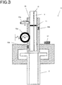
- Fig. 3 is illustrative in schematic of the trocar sensor 5 in the endoscope system 10 according to the second embodiment.
- the endoscope 1 is inserted into the body cavity B through the trocar 2.
- the field-of-view adjustment mechanism 1b is adjusted by operation of the operating input unit 4 to direct the imaging unit 1a to an imaging target Pt.
- the distal end of the imaging unit 1a is provided with a distance sensor 1c that works as a position sensor adapted to measure a distance to the imaging target Pt.
- the field-of-view adjustment mechanism 1b includes at least one electrically operated rotatable joint. More preferably, the electrically operated joint includes a succession of joints because the directionality of the imaging unit 1a is more enhanced. Alternatively, the field-of-view adjustment mechanism 1b may be located outside the body cavity.
- the trocar 2 includes a trocar sensor 5, as depicted in Fig. 3 .
- the trocar sensor 5 includes, and is constructed of, a tilt angle detection sensor 51, an amount-of-advanceable/retractable-movement detection sensor 52 and an amount-of-rotation detection sensor 53.
- the tilt angle detection sensor 51 is provided to detect in which direction the trocar 2 turns with respect to a reference coordinate system.
- the reference coordinate system here is the one that is defined relative to a fixed object such as a patient or the ground; for instance, there is the mention of a coordinate system A with the fulcrum Pb of Fig. 2 as center.
- a variety of sensors such as an acceleration sensor may be used as the tilt angle detection sensor 51.
- the acceleration sensor may detect an acceleration applied thereon to detect in which direction the trocar 2 turns, that is, the tilt angle ⁇ of the trocar 2 with respect to such a coordinate system as shown in Fig. 2 .
- the amount-of-advanceable/retractable-movement detection sensor 52 is provided for detection of the amount of advanceable and retractable movement of a medical instrument such as the endoscope 1 inserted through the trocar 2 in its insertion direction.
- a surgeon such as a physician inserts or ejects a medical instrument through the trocar 2 to operate and move the medical instrument within the patient's body to an unerring position.
- the amount-of-advanceable/retractable-movement detection sensor 52 it is possible to detect the insertion position of the medical instrument relative to the trocar 1 in the form of the amount of advanceable and retractable movement.
- Fig. 2 shows the center axis C of the trocar 1 in the insertion direction by a dashed line.
- the amount-of-advanceable/retractable-movement detection sensor 52 detects the amount of movement parallel with that center axis C in the form of the amount of advanceable and retractable movement.
- the amount-of-advanceable/retractable-movement detection sensor 52 is made up of a combined amount-of-advanceable/retractable-movement detection roller 52a and photosensor 52b.
- the medical instrument such as the endoscope 1 is provided with a advanceable/retractable position detection mark 11 that is capable of being detected by the photosensor 52b.
- the amount-of-rotation detection sensor 53 is provided for detection of the amount of rotation of a medical instrument that rotates in association with operation as by a surgeon. By rotational operation about the center axis C of a medical instrument inserted through the insertion hole 55, it is possible to change the direction of an end effector mounted at the distal end of the medical instrument within the patient's body.
- the amount-of-rotation detection sensor 53 detects this amount of rotation so that in which direction the end effector of the medical instrument turns can be detected.
- the amount-of-rotation detection sensor 53 here is made up of a combined amount-of-rotation detection roller 53a and photosensor 53b.
- the medical instrument such as the endoscope 1 is provided with a advanceable/retractable position detection mark 12 that is capable of being detected by the photosensor 53b.
- trocar sensor 5 located in the trocar 2 has been explained, it is to be understood that sensors having various forms may be used instead.
- a mechanical sensor using a roller is here used for the purpose of detecting the amount of advanceable/retractable movement and rotation, but the amount of advanceable/retractable movement and rotation may also be detected by means of an optical sensor capable of detecting the amount and direction of movement of a surface used for a laser mouse.
- the amounts of advanceable/retractable movement and rotation may be detected by means of a single optical sensor.
- these are easy to detect because various sensors are located within the trocar 2; however, an external sensor located outside the trocar 2 may be used to detect the direction or the direction and position of the medical instrument.
- the tilt angle detection sensor 51 located in the trocar 2 may be located directly on the medical instrument side.
- Fig. 4 is illustrative of one example of the control system for the endoscope system 10 according to the first embodiment.
- the endoscope system 10 is controlled by a control unit (controller) 7.
- a position computation unit 71 is adapted to compute the position of the imaging target Pt shown in Fig. 2 on the basis of information entered from the trocar sensor 5 and distance sensor 1c.
- a position storage unit 72 is adapted to store the position of the imaging target Pt computed by the position computation unit 71.
- a first driving-amount computation unit 73 is adapted to compute the driving amount for a driver unit 8 that drives the field-of-view adjustment mechanism 1b shown in Fig. 2 such that the position of the imaging target Pt computed by the position computation unit 71 lies on the axis of sighting of the endoscope.
- the driver unit 8 may take a form of directly rotating the joint by an electric motor or the like, or a form of rotating the joint indirectly by way of a wire or the like.
- the image storage unit 74 is adapted to store an image taken by the imaging unit 1a.
- the images to be stored may be at least a part of the images taken by the imaging unit 1a.
- a similarity computation unit 75 working as a comparison unit is adapted to compare the previous (before movement) images taken by the imaging unit 1a and stored in the image storage unit 74 with current (after movement) images taken by the imaging unit 1a to compute the degree of similarity.
- the degree of similarity may be computed by a method such as a conventional template matching method.
- a second driving-amount computation unit 76 is adapted to compute the driving amount for the driver unit 8 that drives the field-of-view adjustment mechanism 1b shown in Fig. 2 such that the imaging unit 1a directs from the position where the imaging unit 1a takes the current images to the position where the previously stored images were taken.
- a determination unit 77 is adapted to determine which is used, a sensor-based first driving amount computed by the first driving-amount computation unit 73 or an image-based second driving amount computed by the second driving-amount computation unit 76, from the degree of similarity computed by the similarity computation unit 75.
- a switchover unit 78 is adapted to switch between a normal mode and a tracking mode in response to a signal entered from the operation input unit 4.
- the imaging unit 1a moves, it causes the field of view to move too, and in the tracking mode, the imaging target Pt remains fixed in the field of view even when the imaging unit 1a moves.
- a display unit 6 provided for displaying at least one of the result of determination of the determination unit 77, the mode state switched by the switchover unit 78 and the image.
- Fig. 5 is illustrative of one example of the control flowchart for the endoscope system 10 according to the first embodiment.
- Step 1 it is first determined in Step 1 whether or not the tracking mode of the switchover unit 78 is held on (ST1).
- Step 2 the processing goes to Step 3 in which the image storage unit 74 stores a reference image Pt 0 of the imaging target Pt that is currently being taken by the imaging unit 1a (ST3).
- Fig. 6 is illustrative of a state in which images are stored by the endoscope system 10 according to the first embodiment: Fig. 6(A) is illustrative of the endoscope 1 according to the first embodiment, which directs to the imaging target Pt, Fig. 6(B) is illustrative of the then display unit 6, and Fig. 6(C) is illustrative of the reference image Pt 0 .
- the imaging unit 1a of the endoscope 1 is operated by the surgeon as shown in Fig. 6(A) .
- the image storage unit 74 is instructed by the surgeon to store the images of the imaging target Pt, it allows the reference image Pt 0 of the imaging target Pt to be stored as shown in Fig. 6(C) .
- Step 4 the processing goes to Step 4 in which the positions of the distal end of the endoscope and the imaging target Pt are computed by the position computation unit 71 on the basis of information entered from the trocar sensor 5 and distance sensor 1c and stored by the position storage unit 72 (ST4).
- the sensor-based first driving amount computed by the first driving-amount computation unit 73 or the image-based second driving amount computed by the second driving-amount computation unit 76 is determined by the determination unit 77.
- Step 6 when the degree of similarity P is greater than the given value Pth, the processing goes to Step 7 in which the image-based second driving amount computed by the second driving-amount computation unit 76 is computed (ST7). Then, the processing goes to Step 8 in which the joint is driven according to the second driving amount (ST8).
- Fig. 7 is illustrative of the endoscope 1 after moving to the first position of the endoscope system 10 according to the first embodiment and the then display unit 6:
- Fig. 7(A) is illustrative of the endoscope 1 after moving to the first position of the endoscope system 10 according to the first embodiment
- Fig. 7(B) is illustrative of the then display unit 6
- Fig. 7(C) is illustrative of a target position for the image Pt 1 of the imaging target Pt.
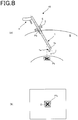
- Fig. 8 is illustrative of the joint that is driven by the endoscope 1 in the endoscope system 10 according to the first embodiment: Fig. 8(A) is illustrative of the joint that is being driven by the endoscope 1 of the endoscope system 10 according to the first embodiment, and Fig. 8(B) is illustrative of the then display unit 6.
- the reference image Pt 0 of the imaging target Pt stored as shown in Fig. 6(B) looks like the current image Pt 1 of the imaging target Pt, as shown in Fig. 7(B) .
- the reference image Pt 0 of the imaging target Pt stored in the image storage unit 74 and the current image Pt 1 of the imaging target Pt are here compared by the similarity computation unit 75 in the control unit 7 for similarity computation.
- the direction and amount of movement in which the current image Pt 1 of the imaging target Pt is moved in such a way as to include at least the center O of the field of view, just like the reference image Pt 0 of the imaging target Pt stored in the image storage unit 74, are here computed by the second driving-amount computation unit 76, as shown in Fig. 7(C) . That is, the second driving amount for driving the field-of-view adjustment mechanism 1b is computed by the second driving-amount computation unit 76.
- the field-of-view adjustment mechanism 1b is driven, as shown in Fig. 8(A) , to vary the orientation of the imaging unit 1a such that the current image Pt 1 of the imaging target Pt is nearly centered in such a way as to include at least the center O of the field of view, as shown in Fig. 8(B) .
- Step 6 when the degree of similarity P is less than the predetermined value Pth, the processing goes to Step 9 in which the sensor-based first driving amount computed by the first driving-amount computation unit 73 is computed (ST9). Then, the joint is driven according to the first driving amount in Step 8.
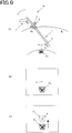
- Fig. 9 is illustrative of the endoscope 1 after moving to the second position of the endoscope system 10 according to the first embodiment and the then display unit 6:
- Fig. 9(A) is illustrative of the endoscope 1 after moving to the second position of the endoscope system 10 according to the first embodiment
- Fig. 9(B) is illustrative of the then display unit 6
- Fig. 9(C) is illustrative of a target position for an image Pt 2 of the imaging target Pt.
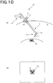
- Fig. 10 is illustrative of the joint that is driven by the endoscope system 10 according to the first embodiment and the then display unit 6:
- Fig. 10(A) is illustrative of the joint that is being driven by the endoscope system 10 according to the first embodiment, and
- Fig. 10(B) is illustrative of the then display unit 6.
- the reference image Pt 0 of the imaging target Pt stored as shown in Fig. 6(B) looks like the current image Pt 2 of the imaging target Pt, as shown in Fig. 9(B) .
- the reference image Pt 0 of the imaging target Pt stored in the image storage unit 74 and the current image Pt 2 of the imaging target Pt are compared by the similarity computation unit 75 in the control unit 7 for similarity computation.
- the direction and angle of the field-of-view adjustment mechanism 1b for nearly centering the current image Pt 2 of the imaging target Pt in such a way as to include at least the center O of the field of view, just like the reference image Pt 0 of the imaging target Pt stored in the image storage unit 74, are here computed by the similarity computation unit 75 in the control unit 7 from measurements obtained through the trocar sensor 5 and distance sensor 1c.
- the second driving amount for driving the field-of-view adjustment mechanism 1b is computed by the second driving-amount computation unit 76.
- the field-of-view adjustment mechanism 1b is driven, as shown in Fig. 10(A) , to vary the orientation of the imaging unit 1a such that the current image Pt 2 of the imaging target Pt is nearly centered in such a way as to include at least the center O of the field of view, as shown in Fig. 10(B) .
- the endoscope system 10 includes an endoscope 1 including an imaging unit 1a that is capable of taking an image of a imaging target Pt, a field-of-view adjustment mechanism 1b for varying an orientation of the imaging unit 1a, an operation input unit 4 for operating the field-of-view adjustment mechanism 1b and a driver unit for driving the field-of-view adjustment mechanism 1b, an endoscopic position sensor (trocar sensor) 5 for detecting a position of the endoscope 1 in the body cavity B, a distance measurement unit (distance sensor) 1c for measuring a distance from a distal end of the endoscope 1 to the imaging target Pt, a position computation unit 71 for computing positions of the distal end of the endoscope and the imaging target Pt on the basis of information from the endoscopic position sensor 5 and distance measurement unit 1c, a position storage unit 72 for storing a position computed by the position computation unit 71, a first driving-amount computation unit 73 for computing a driving amount for the field-of
- the comparison unit 75 includes the image Pt 0 of the imaging target Pt stored in the image storage unit 74, the newly taken image Pt 1 of the imaging target Pt and the similarity computation portion 75, and the determination unit 77 makes the determination depending on the degree of similarity computed by the similarity computation portion 75. It is thus possible to improve on precision.
- the present invention provides a process of controlling the endoscope 1 according to one embodiment, which endoscope 1 includes an imaging unit 1a and a field-of-view adjustment mechanism 1b for varying the orientation of the imaging unit 1a wherein the field-of-view adjustment mechanism 1b is controlled while capturing the desired imaging target, the process including a position computation step of computing the distal end position of the endoscope 1 or the position of the desired imaging target, an image recording step of recording an image taken of the desired imaging target, a position storage step of computing and recording the position of the desired imaging target, an image comparison step of comparing a current image taken by the imaging unit 1a with the previously recorded image of the desired imaging target, a first driving-amount computation step of computing a driving amount for driving the field-of-view adjustment mechanism 1b such that the desired imaging target is positioned on the axis of sighting of the imaging unit 1a, a second driving-amount computation step of computing a driving amount for driving the field-of-view adjustment mechanism 1a in such a way as to include the
- the driving amount is computed, and in the second driving-amount computation step, when both the images compared in the image comparison step are determined as having a high degree of similarity, the driving amount is computed. It is thus possible to improve on precision.
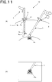
- Fig. 11 shows that there is an obstacle in the endoscope system 10 according to the first embodiment and the then display unit 6:
- Fig. 11(A) shows that there is an obstacle in the endoscope system 10 according to the first embodiment, and Fig. 11(B) is illustrative of the then display unit 6.
- the reference image Pt 0 of the imaging target Pt stored in the image storage unit 74 is compared by the similarity computation unit 75 in the control unit 7 with the current image Pt 1 of the imaging target Pt for similarity computation.
- the direction and angle of the field-of-view adjustment mechanism 1b for centering the current image Pt 1 of the imaging target Pt are here computed by the first driving-amount computation unit 73 from measurements obtained from the trocar sensor 5 and distance sensor 1c, as shown in Fig. 11(B) .
- the first driving amount for driving the field-of-view adjustment mechanism 1b is computed by the first driving-amount computation unit 73, and the field-of-view adjustment mechanism 1b is driven according to the thus computed first driving amount.
- Fig. 12 is representative of one example of the control flowchart for the endoscope system 10 according to the second embodiment.
- Step 6 2 the processing goes to Step 6 2 in which the reference image Pt 0 of the imaging target Pt stored first in the image storage unit 74 is erased and rewritten as the current image Pt 1 of the imaging target Pt that is then again stored (ST6 2 ).
- the field-of-view adjustment mechanism 1b is driven on the re-stored image basis. Note here that when there is an abrupt change due to the appearance of the treatment tool 3 such as forceps shown in Fig. 11 , the field-of-view adjustment mechanism 1b may be driven on the sensor basis.
- the image Pt 0 of the imaging target Pt stored by the image storage unit 74 is erased, rewritten as the newly taken image Pt 1 of the imaging target Pt, and again stored. It is thus possible to improve on precision.
- the endoscope control process includes a first image rewriting step in which when both the images compared in the image comparison step are determined as having a high degree of similarity, the previously stored image is rewritten as the current image taken by the imaging unit 1a. It is thus possible to improve on precision.
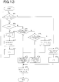
- Fig. 13 is representative of one example of the control flowchart for the endoscope system 10 according to the third embodiment.
- Step 6 1 it is determined whether or not a change with time P ⁇ in the images' degree of similarity is greater than the predetermined value P1 (ST6 1 ).
- Step 6 1 when the change with time P ⁇ in the images' degree of similarity is greater than the given value P1, the processing goes to Step 9 for sensor-based driving.
- Step 6 1 when the change with time P ⁇ in the images' degree of similarity is less than the given value P1, the processing goes to Step 6 2 in which the reference image Pt 0 of the imaging target is erased and rewritten by the image storage unit 74 as the image Pt 1 of the imaging target Pt after the elapse of a given time, and again stored (ST6 2 ), after which the processing goes to Step 7.
- a new image Pt 1 of the imaging target Pt after the elapse of a given time is again stored, and the field-of-view adjustment mechanism 1b is driven according to the image based second driving amount.
- the image Pt 1 of the imaging target after the elapse of a given time after bleeding is again stored as a new reference image.
- the image Pt 0 of the imaging target Pt stored in the image storage unit 74 may be erased, and rewritten and again stored as the new image Pt 1 of the imaging target Pt. It is thus possible to improve on precision.
- the driving amount is computed in the first driving-amount computation step. It is thus possible to improve on precision.
- the endoscope control process described herein further includes the second image rewriting step in which, when the degree of similarity between both the images compared in the image comparison step is determined as being low and the amount of change with time in the degree of similarity is low, the recorded image is rewritten as a current image taken by the imaging unit 1a. It is thus possible to improve on precision.
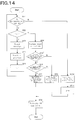
- Fig. 14 is representative of a control flowchart for the endoscope system 10 according to the fourth embodiment.
- Fig. 15 is illustrative of feature points in images taken by the endoscope system 10 according to the fourth embodiment: Fig. 15(A) is illustrative of more feature points in the image, and Fig. 15(B) is illustrative of fewer feature points F in the image.
- the endoscope system 10 according to the fourth embodiment includes a feature point extraction unit for extracting feature points in an image and a feature point computation unit for determining whether or not the amount of extracted feature points is greater than a predetermined amount.
- feature points F in the image are extracted in Step 6' prior to the similarity determination step 6 in the control according to the first embodiment (ST6'). For instance, portions distinguishable from the background, and their points of flexion, etc. may be used as the feature points F in the image, as shown in Fig. 15 .
- Step 6 it is determined whether or not the amount of feature points F in the image is greater than a predetermined amount (ST6").
- ST6 a predetermined amount
- Step 6 when the amount of feature points F in the image is less than the predetermined amount, the processing goes to Step 9 driven on the sensor basis.
- Step 6 when the amount of feature points F in the image is greater than the predetermined amount, the processing goes to Step 6 in which control is implemented as in Embodiment 1.
- the endoscope system described herein includes the feature point extraction unit for extracting feature points in the image Pt 0 of the imaging target Pt stored in the image storage unit 74 or feature points in the new current image Pt 1 of the imaging target Pt, and when the amount of feature points extracted by the feature point extraction unit is less than the predetermined amount, the driver unit 8 is driven according to the first driving amount.
- the endoscope system here is well compatible with even when the amount of feature points is too small for similarity comparison. Note here that the size of an area for which the amount of feature points is determined may be variable.
- the endoscope control process described herein further includes the feature point extraction unit for extracting feature points in the current image taken by the imaging unit 1a, and when the amount of feature points is less than the given amount in the feature point extraction step, the driving amount is computed in the first driving-amount computation step whereas, when the amount of feature points in the feature point extraction unit is more than the given amount, both the images are compared in the image comparison step.
- the endoscope control process here is well compatible with even when the amount of feature points is too small for similarity comparison.
- Fig. 16 is illustrative of one example of the system diagram for the endoscope system 10 according to the fifth embodiment.
- the endoscope system 10 includes a correction unit 91 for correcting input signals from the trocar sensor 5 and distance sensor 1c, and a correction parameter update unit 92 for comparing values computed by the first and second driving-amount computation units 73 and 76 to acquire detection errors for each sensor thereby updating the correction parameter for the correction unit 91.
- the endoscope system 10 described herein may be controlled on the image basis or the sensor basis.
- a sensor may possibly have an initial error on production or an error with time.
- the value computed by the first driving-amount computation unit 73 for computing the driving amount on the sensor basis is compared with the value computed by the second driving-amount computation unit 76 for computing the driving amount on the image basis to find the correction parameter by the correction parameter update unit 92, on the basis of which input signals to the respective sensors are corrected at the correction unit 91.
- the input signals from the trocar sensor 5 and distance sensor 1c are corrected and then entered in the position computation unit 71.
- correction by the correction unit 91 and updating of the correction parameter by the correction parameter update unit 92 may be implemented at any desired point in time.
- the correction parameter may have been updated prior to getting control started, and correction may be carried out by the correction unit 91 at the time of computing the driving amount on the sensor basis or, alternatively, the correction parameter may be updated by the correction parameter update unit 92 at the time of computation of the driving amount on the sensor basis for correction by the correction unit 91.
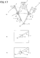
- Fig. 17 is illustrative of a state of storing images in the endoscope system 10 according to the sixth embodiment and the then display unit 6:
- Fig. 17(A) is illustrative of storing images in the endoscope system 10 according to the sixth embodiment
- Fig. 17(B) is illustrative of the then display unit 6
- Fig. 17(C) is representative of the reference image Pt 0 .
- the distal end portion 3a of the treatment tool 3 is used as the imaging target Pt.
- the second trocar 2' through which the treatment tool 3 is inserted is rotatable about a fulcrum Pb', and the second trocar sensor 5' working here as a second position sensor is capable of detecting at least the tilt angle of the second trocar 2' and the amount of insertion of the treatment tool 3 through the second trocar 2' as is the case with the trocar sensor 5.
- the endoscope system 10 according to the sixth embodiment is basically controlled pursuant to a control flowchart similar to that of Fig. 5 .
- the reference image Pt 0 of the imaging target Pt being currently taken by the imaging unit 1a is stored in the image storage unit 74 shown in Fig. 4 .
- the imaging unit 1a of the endoscope 1 is operated by the surgeon such that an image of the distal end portion 3a of the treatment tool 3 that defines the imaging target Pt appears as shown in Fig. 17(B) .
- the reference image Pt 0 of the imaging target Pt it causes the image of the distal end portion 3a of the treatment tool 3 that defines the imaging target Pt to be stored as the reference Pto, as shown in Fig. 17(C) .
- the position of the treatment tool 3 is also stored in addition to the position of the endoscope 1. That is, in Step 4, the positions of the endoscope's distal end and the distal end portion 3a of the treatment tool 3 that defines the imaging target Pt are computed by the position computation unit 71 shown in Fig. 4 on the basis of information entered from the trocar sensor 5 and distance sensor 1c of the endoscope 1 and information entered from the second trocar sensor 5' of the treatment tool 3. Then, those positions are stored in the position storage unit 72.
- the degree of similarity P is computed in Step 6 to determine whether the joint is to be driven on the sensor basis or the image basis.
- Fig. 18 is illustrative of a state where there is a high degree of similarity upon movement of the treatment tool 3 in the endoscope system 10 according to the sixth embodiment and the then display unit 6:
- Fig. 18(A) is illustrative of a state where there is a high degree of similarity upon movement of the treatment tool 3 in the endoscope system 10 according to the sixth embodiment, and
- Fig. 18(B) is illustrative of the then display unit 6.
- Step 7 shown in Fig. 5 in which the image-based second driving amount is computed.
- the field-of-view adjustment mechanism 1b of the endoscope 1 is driven on the basis of the second driving amount to vary the orientation of the imaging unit 1a so that the current image Pt 1 of the imaging target Pt is nearly centered in such a way as to include at least the center O of the display screen, as shown in Fig. 18(B) .
- the endoscope 1 comes to follow the movement of the treatment tool 3.
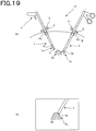
- Fig. 19 is illustrative of a state where there is a low degree of similarity upon movement of the treatment tool 3 in the endoscope system 10 according to the sixth embodiment and the then display unit 6:
- Fig. 19(A) is illustrative of a state where there is a low degree of similarity upon movement of the treatment tool 3 in the endoscope system 10 according to the sixth embodiment, and
- Fig. 19(B) is illustrative of the then display unit 6.
- the processing for the endoscope system 10 goes to Step 9 shown in Fig. 5 in which the sensor-based first driving amount is computed from measurements obtained from the trocar sensor 5 and distance sensor 1c and measurements obtained from the second trocar sensor 5'.
- the endoscope 1 enables the field-of-view adjustment mechanism 1b to be driven to vary the orientation of the imaging unit 1a so that the current image Pt 1 of the imaging target Pt is centered as shown in Fig. 19(B) . In other words, the endoscope 1 comes to follow the movement of the treatment tool 3.
- the distal end portion 3a of the treatment tool 3 is used as the imaging target Pt. It is thus possible to improve on operability because the endoscope 1 is driven following the movement of the treatment tool 3 so that the treatment tool 3 appears always within the display screen.
- Fig. 20 is a schematic view of one example of the endoscope system 10 according to another embodiment.
- the endoscope 1 includes the driver unit 8 that is located outside the body cavity.
- the driver unit 8 includes an actuator by which the endoscope 1 can be driven in a advanceable/retractable movement direction, a tilting direction and a rotating direction about the axis.
- the endoscope system 10 may also be embodied in other possible forms.
- multiple positions may be stored in the position storage unit 72 with a selection unit for selecting the position to be followed out of the stored multiple positions.
- names may be given to the stored multiple positions to display them on the display unit 6.
- the name of a position corresponding to that direction indication mark may be displayed.
- parameters such as positions and driving amounts are figured out by giving input values to a variety of preset mathematical formulae
- desired numerical values may be derived with reference to a preset lookup table (correspondence table) with the input values as key or, alternatively, mathematical formulae may be combined with the table.
Description
- The present invention relates to an endoscope system that is inserted through the body cavity of a patient for surgical operation to view, and apply treatments or the like to, the interior of the patient's body cavity.
- In laparoscopic operation, there are multiple incisions cut open in the abdomen or the like of a patient through which various medical instruments such as cameras, forceps and (electric) scalpel are inserted for viewing and treatments of an affected site while checking up with images taken by a camera. This laparoscopic operation is less invasive of the patient because of limited incision area.
-
Patent Literature 1 discloses the technology of driving an electrically-operated joint of an endoscope such that the tilt angle of a trocar adapted to guide various medical instruments inserted through the patient's abdomen is detected to allow the area of interest to come in the field of view of the endoscope. -
Patent Literature 2 discloses the technology of driving an endoscope such that feature points on a treatment tool are extracted by image processing to allow the treatment tool to come in the field of view. -
- Patent Literature 1:
JP(A) 2007-301378 - Patent Literature 2: Japanese Patent No.
4382894 -
JP 2007 151862 A -
EP 2 158 834 A1 -
WO 2013/054944 A1 discloses how an appropriate stereoscopic image of a subject is readily acquired.
Provided is a stereoscopic endoscope device including two image capture elements spaced apart from each other and disposed at a distal end of an insertion section to be inserted into a subject; an angle changing mechanism that changes a relative angle between optical axes of the image capture elements; a distance sensor that detects the distance from the image capture elements to the subject; and a controller that controls the angle changing mechanism on the basis of the distance detected by the distance sensor. -
WO 2013/067025 A1 discloses devices, systems, and methods for controlling the field of view in imaging systems. For example, in one embodiment an imaging system includes a flexible elongate member sized and shaped for use within an internal structure of a patient, an imaging transducer positioned within the distal portion of the flexible elongate member, an imaging marker positioned to be detectable within a field of view of the imaging transducer, and a controller in communication with the flexible elongate member and configured to adjust a control signal of the flexible elongate member based on the detection of the imaging marker in data received from the flexible elongate member in order to achieve a desired field of view for the imaging transducer. -
EP 1 854 420 A1 - A problem with the technology of
Patent Literature 1 was that there is often an error given rise to upon computation of the distal end position of the endoscope, because the distal end position of the endoscope is computed and driven on the basis of the result measured at a pivot point on the body surface without taking heed of the posture of the endoscope within the body cavity. - A problem with the technology of
Patent Literature 2 was that when feature points on the treatment tool are invisible as by deposition of obstacles or bloods, they cannot be extracted and any image information cannot be obtained, often making it hard to drive the endoscope. - Having been made with the problems in mind, the present invention has for its object to provide an endoscope system for controlling an endoscope such that even when there are changes in environments available in the body cavity, the area of interest remains within the field of view.
- According to one embodiment of the invention, an endoscope system includes
an endoscope including an imaging unit that is capable of taking an image of an imaging target, a field-of-view adjustment mechanism for varying an orientation of the imaging unit and a driver unit for driving the field-of-view adjustment mechanism,
an endoscopic position sensor for detecting a position of the endoscope in the body cavity,
a distance measurement unit for measuring a distance from a distal end of the endoscope to the imaging target,
a position computation unit for computing positions of the distal end of the endoscope and the imaging target on the basis of information from the endoscopic position sensor and the distance measurement unit,
a position storage unit for storing a position of the imaging target computed by the position computation unit,
a first driving-amount computation unit for computing a driving amount for the field-of-view adjustment mechanism using the position stored in the position storage unit and the position of the distal end of the endoscope,
an image storage unit for storing the image of the imaging target taken by the imaging unit,
a comparison unit for comparing the image of the imaging target stored in the image storage unit with a newly taken image of the imaging target,
a second driving-amount computation unit for computing a driving amount for the field-of-view adjustment mechanism depending on a result of comparison by the comparison unit, and
a determination unit for determining which is used, a first driving amount computed by the first driving-amount computation unit or a second driving amount computed by the second driving-amount computation unit, to drive the driver unit. - In the endoscope system according to one embodiment of the invention, the comparison unit includes a similarity computation unit for computing a degree of similarity between the image of the imaging target stored in the image storage unit and the newly taken image of the imaging target, and the determination unit makes a determination depending on the degree of similarity computed by the similarity computation unit.
- In the endoscope system according to one embodiment of the invention, after the degree of similarity computed by the similarity computation unit is determined as being higher than a predetermined value, the image of the imaging target stored in the image storage unit is erased and rewritten as the newly taken image of the imaging target, which is then again stored.
- In the endoscope system according to one embodiment of the invention, when a change with time in the degree of similarity is less than a predetermined value after the degree of similarity computed by the similarity computation unit is determined as being lower than the predetermined value, the image of the imaging target stored in the image storage unit is erased and rewritten as the newly taken image of the imaging target, which is then again stored.
- According to one embodiment of the invention, the endoscope system includes a feature point extraction unit for extracting feature points in the image of the imaging target stored in the image storage unit or the newly taken image of the imaging target, wherein when an amount of feature points extracted by the feature point extraction unit is less than a predetermined amount, the driver unit is driven according to the first driving amount.
- According to one embodiment of the invention, the endoscope system includes an endoscopic trocar through which the endoscope is inserted into the body cavity, wherein the endoscopic position sensor includes an endoscopic trocar sensor attached to the endoscopic trocar for measuring a distal end position of the imaging unit, and a distance sensor attached to the imaging unit for measuring a distance to the imaging target.
- According to one embodiment of the invention, the endoscope system includes a display unit for displaying which is determined by the determination unit, the first driving amount or the second driving amount.
- According to one embodiment of the invention, the endoscope system includes a correction unit for correcting an input signal from the endoscopic position sensor and a correction parameter update unit for comparing values computed by the first driving-amount computation unit and the second driving-amount computation unit to acquire an detection error for the endoscopic position sensor thereby updating a correction parameter of the correction unit.
- According to one embodiment of the invention, the endoscope system includes a treatment tool for applying treatments to an affected site in the body cavity, a treatment tool trocar through which the treatment tool is inserted, and a treatment tool position sensor attached to the treatment tool trocar for measuring a distal end position of the treatment tool, wherein:
the field-of-view adjustment mechanism is driven according to a driving amount computed by the first or the second driving-amount computation unit from measurements of the endoscopic position sensor and the treatment tool position sensor to allow the treatment tool to keep track of the endoscope. - According to one embodiment of the invention, there is an endoscope control process according to
claim 10 provided. - According to one embodiment of the invention, in the first driving-amount computation step of the endoscope control process, the driving amount is computed at a time when the degree of similarity between both images compared in the image comparison step is determined as being low, and in the second driving-amount computation step, the driving amount is computed at a time when the degree of similarity between both images compared in the image comparison step is determined as being high.
- According to one embodiment of the invention, the endoscope control process further includes a first image rewriting step of rewriting the recorded image as a current image being taken by the imaging unit at a time when the degree of similarity between both images compared in the image comparison step is determined as being high.
- According to one embodiment of the invention, in the first driving-amount computation step of the endoscope control process, the driving amount is computed at a time when the degree of similarity between both images compared in the image comparison step is determined as being low and an amount of change-with-time in the degree of similarity is greater than a given value.
- According to one embodiment of the invention, the endoscope control process further includes a second image rewriting step of rewriting the recorded image as a current image being taken by the imaging unit at a time when the degree of similarity between both images compared in the image comparison step is determined as being low and an amount of change-with-time in the degree of similarity is less than a given value.
- According to one embodiment of the invention, the endoscope control process further includes a feature point extraction step of extracting feature points in a current image being taken by the imaging unit, wherein:
- when an amount of feature points in the feature point extraction step is less than a given amount, the driving amount is computed by the first driving-amount computation step, and
- when an amount of feature points in the feature point extraction step is greater than a given amount, both the images are compared in the image comparison step.
- With the endoscope system according to one embodiment of the invention, it is possible to control the endoscope such that even when there are changes in environments available in the body cavity, the area of interest remains within the field of view.
-
-
Fig. 1 is a schematic view of one example of the endoscope system according to one embodiment. -
Fig. 2 is a schematic view of one example of the endoscope system according to the first embodiment. -
Fig. 3 is a schematic view of the trocar sensor in the endoscope system according to the first embodiment. -
Fig. 4 is illustrative of one example of the control system for the endoscope system according to the first embodiment. -
Fig. 5 is illustrative of one example of the control flowchart for the endoscope according to the first embodiment. -
Fig. 6 is illustrative of a state in which the endoscope according to the first embodiment stores an image. -
Fig. 7 is illustrative of the endoscope after moving to a first position of the endoscope system according to the first embodiment. -
Fig. 8 is illustrative of a state in which the joint is driven by theendoscope 1 in the endoscope system according to the first embodiment. -
Fig. 9 is illustrative of the endoscope after moving to a second position of the endoscope system according to the first embodiment. -
Fig. 10 is illustrative of a state in which the joint is driven by the endoscope system according to the first embodiment. -
Fig. 11 is illustrative of the endoscope system according to the first embodiment wherein there is an obstacle. -
Fig. 12 is illustrative of one example of the control flowchart for the endoscope system according to the second embodiment. -
Fig. 13 is illustrative of one example of the control flowchart for the endoscope system according to the third embodiment. -
Fig. 14 is illustrative of one example of the control flowchart for the endoscope system according to the fourth embodiment. -
Fig. 15 is illustrative of feature points in an image taken by the endoscope system according to the fourth embodiment. -
Fig. 16 is illustrative of one example of the system diagram for the endoscope system according to the fifth embodiment. -
Fig. 17 is illustrative of a state in which an image is stored by the endoscope system according to the sixth embodiment. -
Fig. 18 is illustrative of a state having a high degree of similarity upon movement of thetreatment tool 3 in the endoscope system according to the sixth embodiment. -
Fig. 19 is illustrative of a state having a low degree of similarity upon movement of thetreatment tool 3 in the endoscope system according to the sixth embodiment. -
Fig. 20 is a schematic view of one example of theendoscope system 10 according to a further embodiment. - Some embodiments will now be explained.
-
Fig. 1 is illustrative in schematic of one example of theendoscope system 10 according to the embodiment described herein. - In laparoscopic surgery, tubes called trocars (channels) 2a to 2d are inserted through incisions cut open in the body wall of a patient, and various medical instruments are inserted into the patient's body cavity by way of these
trocars 2a to 2d.Fig. 1 shows that theendoscope 1 is being inserted through thetrocar 2b and atreatment tool 3 such as forceps is being inserted through thetrocar 2d. The distal end of theendoscope 1 inserted through the patient's body cavity by way of thetrocar 2b is provided with animaging unit 1a and a field (of view)adjustment mechanism 1b capable of adjusting angles or the like such that an affected site, a treatment tool or the like comes within the field of view. A distal-end portion of thetreatment tool 3 inserted into the patient's body cavity by way of thetrocar 2d is provided with a distal-end portion 3a such as a grip. A surgeon M adjusts the field-of-view adjustment mechanism 1b of theendoscope 1 and operates thetreatment tool 3 while viewing adisplay unit 6 such as a monitor on which an image of the affected site taken by theimaging unit 1a appears, thereby opening or closing the distal-end portion 3a for treatment of the affected site. -
Fig. 2 is illustrative in schematic of one example of theendoscope system 10 according to the first embodiment, andFig. 3 is illustrative in schematic of thetrocar sensor 5 in theendoscope system 10 according to the second embodiment. - The
endoscope 1 is inserted into the body cavity B through thetrocar 2. In theendoscope 1, the field-of-view adjustment mechanism 1b is adjusted by operation of the operatinginput unit 4 to direct theimaging unit 1a to an imaging target Pt. Preferably, the distal end of theimaging unit 1a is provided with adistance sensor 1c that works as a position sensor adapted to measure a distance to the imaging target Pt. - It is here to be noted that the field-of-
view adjustment mechanism 1b includes at least one electrically operated rotatable joint. More preferably, the electrically operated joint includes a succession of joints because the directionality of theimaging unit 1a is more enhanced. Alternatively, the field-of-view adjustment mechanism 1b may be located outside the body cavity. - The
trocar 2 according to the embodiment described herein includes atrocar sensor 5, as depicted inFig. 3 . Thetrocar sensor 5 includes, and is constructed of, a tiltangle detection sensor 51, an amount-of-advanceable/retractable-movement detection sensor 52 and an amount-of-rotation detection sensor 53. - The tilt
angle detection sensor 51 is provided to detect in which direction thetrocar 2 turns with respect to a reference coordinate system. The reference coordinate system here is the one that is defined relative to a fixed object such as a patient or the ground; for instance, there is the mention of a coordinate system A with the fulcrum Pb ofFig. 2 as center. A variety of sensors such as an acceleration sensor may be used as the tiltangle detection sensor 51. The acceleration sensor may detect an acceleration applied thereon to detect in which direction thetrocar 2 turns, that is, the tilt angle θ of thetrocar 2 with respect to such a coordinate system as shown inFig. 2 . - The amount-of-advanceable/retractable-movement detection sensor 52 is provided for detection of the amount of advanceable and retractable movement of a medical instrument such as the
endoscope 1 inserted through thetrocar 2 in its insertion direction. A surgeon such as a physician inserts or ejects a medical instrument through thetrocar 2 to operate and move the medical instrument within the patient's body to an unerring position. With the amount-of-advanceable/retractable-movement detection sensor 52, it is possible to detect the insertion position of the medical instrument relative to thetrocar 1 in the form of the amount of advanceable and retractable movement.Fig. 2 shows the center axis C of thetrocar 1 in the insertion direction by a dashed line. The amount-of-advanceable/retractable-movement detection sensor 52 detects the amount of movement parallel with that center axis C in the form of the amount of advanceable and retractable movement. In the embodiment described herein, the amount-of-advanceable/retractable-movement detection sensor 52 is made up of a combined amount-of-advanceable/retractable-movement detection roller 52a andphotosensor 52b. Preferably in this case, the medical instrument such as theendoscope 1 is provided with a advanceable/retractableposition detection mark 11 that is capable of being detected by thephotosensor 52b. - The amount-of-rotation detection sensor 53 is provided for detection of the amount of rotation of a medical instrument that rotates in association with operation as by a surgeon. By rotational operation about the center axis C of a medical instrument inserted through the
insertion hole 55, it is possible to change the direction of an end effector mounted at the distal end of the medical instrument within the patient's body. The amount-of-rotation detection sensor 53 detects this amount of rotation so that in which direction the end effector of the medical instrument turns can be detected. The amount-of-rotation detection sensor 53 here is made up of a combined amount-of-rotation detection roller 53a andphotosensor 53b. Preferably in this case, the medical instrument such as theendoscope 1 is provided with a advanceable/retractableposition detection mark 12 that is capable of being detected by thephotosensor 53b. - While the
trocar sensor 5 located in thetrocar 2 has been explained, it is to be understood that sensors having various forms may be used instead. For instance, a mechanical sensor using a roller is here used for the purpose of detecting the amount of advanceable/retractable movement and rotation, but the amount of advanceable/retractable movement and rotation may also be detected by means of an optical sensor capable of detecting the amount and direction of movement of a surface used for a laser mouse. In this case, the amounts of advanceable/retractable movement and rotation may be detected by means of a single optical sensor. For medical system according to the embodiment described herein, it is required to know the direction or the direction and position of a medical instrument inserted through the body of a patient. In the embodiment described herein, these are easy to detect because various sensors are located within thetrocar 2; however, an external sensor located outside thetrocar 2 may be used to detect the direction or the direction and position of the medical instrument. For instance, the tiltangle detection sensor 51 located in thetrocar 2 may be located directly on the medical instrument side. -
Fig. 4 is illustrative of one example of the control system for theendoscope system 10 according to the first embodiment. - The
endoscope system 10 is controlled by a control unit (controller) 7. Aposition computation unit 71 is adapted to compute the position of the imaging target Pt shown inFig. 2 on the basis of information entered from thetrocar sensor 5 anddistance sensor 1c. Aposition storage unit 72 is adapted to store the position of the imaging target Pt computed by theposition computation unit 71. A first driving-amount computation unit 73 is adapted to compute the driving amount for adriver unit 8 that drives the field-of-view adjustment mechanism 1b shown inFig. 2 such that the position of the imaging target Pt computed by theposition computation unit 71 lies on the axis of sighting of the endoscope. Thedriver unit 8 may take a form of directly rotating the joint by an electric motor or the like, or a form of rotating the joint indirectly by way of a wire or the like. - The
image storage unit 74 is adapted to store an image taken by theimaging unit 1a. The images to be stored may be at least a part of the images taken by theimaging unit 1a. Asimilarity computation unit 75 working as a comparison unit is adapted to compare the previous (before movement) images taken by theimaging unit 1a and stored in theimage storage unit 74 with current (after movement) images taken by theimaging unit 1a to compute the degree of similarity. The degree of similarity may be computed by a method such as a conventional template matching method. A second driving-amount computation unit 76 is adapted to compute the driving amount for thedriver unit 8 that drives the field-of-view adjustment mechanism 1b shown inFig. 2 such that theimaging unit 1a directs from the position where theimaging unit 1a takes the current images to the position where the previously stored images were taken. - A
determination unit 77 is adapted to determine which is used, a sensor-based first driving amount computed by the first driving-amount computation unit 73 or an image-based second driving amount computed by the second driving-amount computation unit 76, from the degree of similarity computed by thesimilarity computation unit 75. - A
switchover unit 78 is adapted to switch between a normal mode and a tracking mode in response to a signal entered from theoperation input unit 4. In the normal mode, as theimaging unit 1a moves, it causes the field of view to move too, and in the tracking mode, the imaging target Pt remains fixed in the field of view even when theimaging unit 1a moves. - It is here to be appreciated that there may be a
display unit 6 provided for displaying at least one of the result of determination of thedetermination unit 77, the mode state switched by theswitchover unit 78 and the image. -
Fig. 5 is illustrative of one example of the control flowchart for theendoscope system 10 according to the first embodiment. - In the
endoscope system 10 according to the first embodiment, it is first determined inStep 1 whether or not the tracking mode of theswitchover unit 78 is held on (ST1). - When the tracking mode of the
switchover unit 78 is held on inStep 1, the processing goes toStep 2 in which it is determined whether or not the counter is i=0 (ST2). - When the counter is i=0 in
Step 2, the processing goes toStep 3 in which theimage storage unit 74 stores a reference image Pt0 of the imaging target Pt that is currently being taken by theimaging unit 1a (ST3). -
Fig. 6 is illustrative of a state in which images are stored by theendoscope system 10 according to the first embodiment:Fig. 6(A) is illustrative of theendoscope 1 according to the first embodiment, which directs to the imaging target Pt,Fig. 6(B) is illustrative of thethen display unit 6, andFig. 6(C) is illustrative of the reference image Pt0. - In order for the imaging target Pt to appear on the display unit as shown in
Fig. 6(B) , theimaging unit 1a of theendoscope 1 is operated by the surgeon as shown inFig. 6(A) . In this state, as theimage storage unit 74 is instructed by the surgeon to store the images of the imaging target Pt, it allows the reference image Pt0 of the imaging target Pt to be stored as shown inFig. 6(C) . - Then, the processing goes to
Step 4 in which the positions of the distal end of the endoscope and the imaging target Pt are computed by theposition computation unit 71 on the basis of information entered from thetrocar sensor 5 anddistance sensor 1c and stored by the position storage unit 72 (ST4). - Then, the processing goes to
Step 5 in which the counter is set to i=1 (ST5), and returns back toStep 1. - In
Step 2, when the counter is not i=0, the processing goes toStep 6 in which the degree of similarity between the reference image Pt0 of the previously stored imaging target Pt and the current reference image Pt1 of the imaging target Pt is computed by thesimilarity computation unit 75 and whether or not the degree of similarity P is greater than a given value Pth is determined by the determination unit 77 (ST6). In other words, which is used, the sensor-based first driving amount computed by the first driving-amount computation unit 73 or the image-based second driving amount computed by the second driving-amount computation unit 76, is determined by thedetermination unit 77. - In
Step 6, when the degree of similarity P is greater than the given value Pth, the processing goes toStep 7 in which the image-based second driving amount computed by the second driving-amount computation unit 76 is computed (ST7). Then, the processing goes toStep 8 in which the joint is driven according to the second driving amount (ST8). -
Fig. 7 is illustrative of theendoscope 1 after moving to the first position of theendoscope system 10 according to the first embodiment and the then display unit 6:Fig. 7(A) is illustrative of theendoscope 1 after moving to the first position of theendoscope system 10 according to the first embodiment,Fig. 7(B) is illustrative of thethen display unit 6, andFig. 7(C) is illustrative of a target position for the image Pt1 of the imaging target Pt. -
Fig. 8 is illustrative of the joint that is driven by theendoscope 1 in theendoscope system 10 according to the first embodiment:Fig. 8(A) is illustrative of the joint that is being driven by theendoscope 1 of theendoscope system 10 according to the first embodiment, andFig. 8(B) is illustrative of thethen display unit 6. - As the
endoscope 1 is moved by the surgeon from the storage position shown inFig. 6(A) to the first position shown inFig. 7(A) , the reference image Pt0 of the imaging target Pt stored as shown inFig. 6(B) looks like the current image Pt1 of the imaging target Pt, as shown inFig. 7(B) . The reference image Pt0 of the imaging target Pt stored in theimage storage unit 74 and the current image Pt1 of the imaging target Pt are here compared by thesimilarity computation unit 75 in thecontrol unit 7 for similarity computation. - When the degree of similarity P is greater than the predetermined value Pth, the direction and amount of movement in which the current image Pt1 of the imaging target Pt is moved in such a way as to include at least the center O of the field of view, just like the reference image Pt0 of the imaging target Pt stored in the
image storage unit 74, are here computed by the second driving-amount computation unit 76, as shown inFig. 7(C) . That is, the second driving amount for driving the field-of-view adjustment mechanism 1b is computed by the second driving-amount computation unit 76. - After that, the field-of-
view adjustment mechanism 1b is driven, as shown inFig. 8(A) , to vary the orientation of theimaging unit 1a such that the current image Pt1 of the imaging target Pt is nearly centered in such a way as to include at least the center O of the field of view, as shown inFig. 8(B) . - In
Step 6, when the degree of similarity P is less than the predetermined value Pth, the processing goes to Step 9 in which the sensor-based first driving amount computed by the first driving-amount computation unit 73 is computed (ST9). Then, the joint is driven according to the first driving amount inStep 8. -
Fig. 9 is illustrative of theendoscope 1 after moving to the second position of theendoscope system 10 according to the first embodiment and the then display unit 6:Fig. 9(A) is illustrative of theendoscope 1 after moving to the second position of theendoscope system 10 according to the first embodiment,Fig. 9(B) is illustrative of thethen display unit 6, andFig. 9(C) is illustrative of a target position for an image Pt2 of the imaging target Pt. -
Fig. 10 is illustrative of the joint that is driven by theendoscope system 10 according to the first embodiment and the then display unit 6:Fig. 10(A) is illustrative of the joint that is being driven by theendoscope system 10 according to the first embodiment, andFig. 10(B) is illustrative of thethen display unit 6. - As the
endoscope 1 is moved by the surgeon from the storage position shown inFig. 6(A) to the second position shown inFig. 9(A) , the reference image Pt0 of the imaging target Pt stored as shown inFig. 6(B) looks like the current image Pt2 of the imaging target Pt, as shown inFig. 9(B) . The reference image Pt0 of the imaging target Pt stored in theimage storage unit 74 and the current image Pt2 of the imaging target Pt are compared by thesimilarity computation unit 75 in thecontrol unit 7 for similarity computation. - When the degree of similarity P is less than the predetermined value Pth, the direction and angle of the field-of-
view adjustment mechanism 1b for nearly centering the current image Pt2 of the imaging target Pt in such a way as to include at least the center O of the field of view, just like the reference image Pt0 of the imaging target Pt stored in theimage storage unit 74, are here computed by thesimilarity computation unit 75 in thecontrol unit 7 from measurements obtained through thetrocar sensor 5 anddistance sensor 1c. In other words, the second driving amount for driving the field-of-view adjustment mechanism 1b is computed by the second driving-amount computation unit 76. - After that, the field-of-
view adjustment mechanism 1b is driven, as shown inFig. 10(A) , to vary the orientation of theimaging unit 1a such that the current image Pt2 of the imaging target Pt is nearly centered in such a way as to include at least the center O of the field of view, as shown inFig. 10(B) . - It is here to be appreciated that in
Step 1, when the tracking mode of theswitchover unit 78 is held off, the processing goes to Step 10 in which the driving amount is computed from a user interface (ST10). Then, the processing goes to Step 11 in which the counter is set to i=0 (ST11). After that, the joint is driven inStep 8 according to the first driving amount. - As described above, the endoscope system 10 according to one embodiment includes an endoscope 1 including an imaging unit 1a that is capable of taking an image of a imaging target Pt, a field-of-view adjustment mechanism 1b for varying an orientation of the imaging unit 1a, an operation input unit 4 for operating the field-of-view adjustment mechanism 1b and a driver unit for driving the field-of-view adjustment mechanism 1b, an endoscopic position sensor (trocar sensor) 5 for detecting a position of the endoscope 1 in the body cavity B, a distance measurement unit (distance sensor) 1c for measuring a distance from a distal end of the endoscope 1 to the imaging target Pt, a position computation unit 71 for computing positions of the distal end of the endoscope and the imaging target Pt on the basis of information from the endoscopic position sensor 5 and distance measurement unit 1c, a position storage unit 72 for storing a position computed by the position computation unit 71, a first driving-amount computation unit 73 for computing a driving amount for the field-of-view adjustment mechanism 1b depending on position information from the position storage unit 72, an image storage unit 74 for storing an image Pt0 of the imaging target Pt taken by the imaging unit 1a, a comparison unit 75 for comparing the image Pt0 of the imaging target Pt stored in the image storage unit 74 with a newly taken image Pt1 of the imaging target Pt, a second driving-amount computation unit 76 for computing a driving amount for the field-of-view adjustment mechanism 1b depending on a result of comparison by the comparison unit 75, and a determination unit 77 for determining which is used, a first driving amount computed by the first driving-amount computation unit 73 or a second driving amount computed by the second driving-amount computation unit 76, to drive the driver unit 8. It is thus possible to control the
endoscope 1 such that the area of interest Pt remains within the field of view even when there are changes in an environment in the body cavity B. - The
comparison unit 75 includes the image Pt0 of the imaging target Pt stored in theimage storage unit 74, the newly taken image Pt1 of the imaging target Pt and thesimilarity computation portion 75, and thedetermination unit 77 makes the determination depending on the degree of similarity computed by thesimilarity computation portion 75. It is thus possible to improve on precision. - Further, the present invention provides a process of controlling the endoscope 1 according to one embodiment, which endoscope 1 includes an imaging unit 1a and a field-of-view adjustment mechanism 1b for varying the orientation of the imaging unit 1a wherein the field-of-view adjustment mechanism 1b is controlled while capturing the desired imaging target, the process including a position computation step of computing the distal end position of the endoscope 1 or the position of the desired imaging target, an image recording step of recording an image taken of the desired imaging target, a position storage step of computing and recording the position of the desired imaging target, an image comparison step of comparing a current image taken by the imaging unit 1a with the previously recorded image of the desired imaging target, a first driving-amount computation step of computing a driving amount for driving the field-of-view adjustment mechanism 1b such that the desired imaging target is positioned on the axis of sighting of the imaging unit 1a, a second driving-amount computation step of computing a driving amount for driving the field-of-view adjustment mechanism 1a in such a way as to include the center of the image of the desired imaging target, and a driving step of driving the field-of-view adjustment mechanism 1b from the driving amount computed in either one of the first and second driving-amount computation steps. It is thus possible to control the
endoscope 1 such that the area of interest Pt remains within the field of view, even when there are changes in environments within the body cavity B. - In the first driving-amount computation step in the endoscope control process, when both the images compared in the image comparison step are determined as having a low degree of similarity, the driving amount is computed, and in the second driving-amount computation step, when both the images compared in the image comparison step are determined as having a high degree of similarity, the driving amount is computed. It is thus possible to improve on precision.
- Reference is then made to a certain case where the degree of similarity is determined as being low for the reason of the presence of an obstacle.
-
Fig. 11 shows that there is an obstacle in theendoscope system 10 according to the first embodiment and the then display unit 6:Fig. 11(A) shows that there is an obstacle in theendoscope system 10 according to the first embodiment, andFig. 11(B) is illustrative of thethen display unit 6. - When a
treatment tool 3 such as forceps is used by the surgeon together with theendoscope 1, there is sometimes anobstacle 3 such as forceps present in front of the imaging target Pt, as depicted inFig. 11(A) . The reference image Pt0 of the imaging target Pt stored in theimage storage unit 74 is compared by thesimilarity computation unit 75 in thecontrol unit 7 with the current image Pt1 of the imaging target Pt for similarity computation. - When the degree of similarity P is less than the given value Pth, the direction and angle of the field-of-
view adjustment mechanism 1b for centering the current image Pt1 of the imaging target Pt are here computed by the first driving-amount computation unit 73 from measurements obtained from thetrocar sensor 5 anddistance sensor 1c, as shown inFig. 11(B) . In other words, the first driving amount for driving the field-of-view adjustment mechanism 1b is computed by the first driving-amount computation unit 73, and the field-of-view adjustment mechanism 1b is driven according to the thus computed first driving amount. -
Fig. 12 is representative of one example of the control flowchart for theendoscope system 10 according to the second embodiment. - Referring to control of the
endoscope system 10 according to the second embodiment, after the degree of similarity P between the reference image Pt0 of the imaging target Pt stored first at the counter i=0 and the current image Pt1 of the imaging target Pt then at the counter i=1 is determined as being higher than the given value Pth in thesimilarity determination Step 6 in the control process according to the first embodiment, the processing goes toStep 62 in which the reference image Pt0 of the imaging target Pt stored first in theimage storage unit 74 is erased and rewritten as the current image Pt1 of the imaging target Pt that is then again stored (ST62). - For instance, presume now that the
endoscope system 10 is placed in an initial state as shown inFig. 6(A) with the counter set to the initial turn i=0 and the reference image Pt0 of the imaging target ofFig. 6(C) is stored. At the next counter turn i=1, there is a new state appearing as shown inFig. 8 , and when the degree of similarity between it and the reference image Pt0 of the imaging target ofFig. 6(C) is determined as being high, the current image Pt1 of the imaging target Pt ofFig. 8(B) is overwritten and stored instead of the reference image Pt0 of the imaging target Pt ofFig. 6(C) . - At the next turn, there is a state appearing as shown in
Fig. 10 , and when the degree of similarity between the current image Pt2 of the imaging target Pt ofFig. 10(B) and the previous image Pt1 of the imaging target Pt ofFig. 8(B) is determined as being high, the current image Pt2 of the imaging target Pt shown inFig. 10(B) is overwritten and stored instead of the previous image Pt1 of the imaging target Pt shown inFig. 8(B) . - That is, unless there is any abrupt change in the imaging target Pt, the field-of-
view adjustment mechanism 1b is driven on the re-stored image basis. Note here that when there is an abrupt change due to the appearance of thetreatment tool 3 such as forceps shown inFig. 11 , the field-of-view adjustment mechanism 1b may be driven on the sensor basis. - Thus, after the degree of similarity computed by the
similarity computation unit 75 is determined as being higher than the predetermined value, the image Pt0 of the imaging target Pt stored by theimage storage unit 74 is erased, rewritten as the newly taken image Pt1 of the imaging target Pt, and again stored. It is thus possible to improve on precision. - The endoscope control process includes a first image rewriting step in which when both the images compared in the image comparison step are determined as having a high degree of similarity, the previously stored image is rewritten as the current image taken by the
imaging unit 1a. It is thus possible to improve on precision. -
Fig. 13 is representative of one example of the control flowchart for theendoscope system 10 according to the third embodiment. - Referring to another control of the
endoscope system 10 according to the third embodiment, after the degree of similarity P between the reference image Pt0 of the imaging target Pt stored first at the counter i=0 and the current image Pt1 of the imaging target Pt at the counter i=1 is determined as being lower than the given value Pth in thesimilarity determination Step 6 in the control process according to the first embodiment, the processing goes toStep 61 in which it is determined whether or not a change with time Pδ in the images' degree of similarity is greater than the predetermined value P1 (ST61). - In
Step 61, when the change with time Pδ in the images' degree of similarity is greater than the given value P1, the processing goes to Step 9 for sensor-based driving. - In
Step 61, when the change with time Pδ in the images' degree of similarity is less than the given value P1, the processing goes toStep 62 in which the reference image Pt0 of the imaging target is erased and rewritten by theimage storage unit 74 as the image Pt1 of the imaging target Pt after the elapse of a given time, and again stored (ST62), after which the processing goes toStep 7. - That is, when there is less change with time even upon abrupt changes in the imaging target Pt, a new image Pt1 of the imaging target Pt after the elapse of a given time is again stored, and the field-of-
view adjustment mechanism 1b is driven according to the image based second driving amount. For instance, when, even with a part of the affected site bleeding, the change in the image Pt1 of the imaging target Pt remains less and stable after the elapse of a given time after bleeding, it is preferable that the image Pt1 of the imaging target after the elapse of a given time after bleeding is again stored as a new reference image. - When the change with time of the degree of similarity is lower than the predetermined value after the degree of similarity computed by the
similarity computation unit 75 is determined as being lower than the predetermined value, the image Pt0 of the imaging target Pt stored in theimage storage unit 74 may be erased, and rewritten and again stored as the new image Pt1 of the imaging target Pt. It is thus possible to improve on precision. - Referring to the endoscope control process, when the degree of similarity between both the images is determined as being low in the image comparison step and the amount of change with time in the degree of similarity is greater than the given value, the driving amount is computed in the first driving-amount computation step. It is thus possible to improve on precision.
- The endoscope control process described herein further includes the second image rewriting step in which, when the degree of similarity between both the images compared in the image comparison step is determined as being low and the amount of change with time in the degree of similarity is low, the recorded image is rewritten as a current image taken by the
imaging unit 1a. It is thus possible to improve on precision. -
Fig. 14 is representative of a control flowchart for theendoscope system 10 according to the fourth embodiment.Fig. 15 is illustrative of feature points in images taken by theendoscope system 10 according to the fourth embodiment:Fig. 15(A) is illustrative of more feature points in the image, andFig. 15(B) is illustrative of fewer feature points F in the image. - The
endoscope system 10 according to the fourth embodiment includes a feature point extraction unit for extracting feature points in an image and a feature point computation unit for determining whether or not the amount of extracted feature points is greater than a predetermined amount. In control of theendoscope system 10 according to the fourth embodiment, feature points F in the image are extracted in Step 6' prior to thesimilarity determination step 6 in the control according to the first embodiment (ST6'). For instance, portions distinguishable from the background, and their points of flexion, etc. may be used as the feature points F in the image, as shown inFig. 15 . - Then, the processing goes to
Step 6" in which it is determined whether or not the amount of feature points F in the image is greater than a predetermined amount (ST6"). In an area including a fewer feature points F such as a nearly central area shown typically inFig. 15(B) , any unerring degree of similarity cannot be obtained through comparison. - For this reason, in
Step 6", when the amount of feature points F in the image is less than the predetermined amount, the processing goes to Step 9 driven on the sensor basis. - In
Step 6", when the amount of feature points F in the image is greater than the predetermined amount, the processing goes toStep 6 in which control is implemented as inEmbodiment 1. - It is here to be noted that the extraction of feature points F and the determination of the amount of feature points F implemented in
Steps 6' and 6" may be carried out at any desired point in time prior to the determination of the degree of similarity inStep 6. - Thus, the endoscope system described herein includes the feature point extraction unit for extracting feature points in the image Pt0 of the imaging target Pt stored in the
image storage unit 74 or feature points in the new current image Pt1 of the imaging target Pt, and when the amount of feature points extracted by the feature point extraction unit is less than the predetermined amount, thedriver unit 8 is driven according to the first driving amount. Thus, the endoscope system here is well compatible with even when the amount of feature points is too small for similarity comparison. Note here that the size of an area for which the amount of feature points is determined may be variable. - The endoscope control process described herein further includes the feature point extraction unit for extracting feature points in the current image taken by the
imaging unit 1a, and when the amount of feature points is less than the given amount in the feature point extraction step, the driving amount is computed in the first driving-amount computation step whereas, when the amount of feature points in the feature point extraction unit is more than the given amount, both the images are compared in the image comparison step. Thus, the endoscope control process here is well compatible with even when the amount of feature points is too small for similarity comparison. -
Fig. 16 is illustrative of one example of the system diagram for theendoscope system 10 according to the fifth embodiment. - The
endoscope system 10 according to the fifth embodiment includes acorrection unit 91 for correcting input signals from thetrocar sensor 5 anddistance sensor 1c, and a correctionparameter update unit 92 for comparing values computed by the first and second driving-amount computation units correction unit 91. - The
endoscope system 10 described herein may be controlled on the image basis or the sensor basis. A sensor may possibly have an initial error on production or an error with time. In theendoscope system 10 according to the fifth embodiment, therefore, the value computed by the first driving-amount computation unit 73 for computing the driving amount on the sensor basis is compared with the value computed by the second driving-amount computation unit 76 for computing the driving amount on the image basis to find the correction parameter by the correctionparameter update unit 92, on the basis of which input signals to the respective sensors are corrected at thecorrection unit 91. Thus, the input signals from thetrocar sensor 5 anddistance sensor 1c are corrected and then entered in theposition computation unit 71. - By correcting the input signals to the
respective sensor correction unit 91, it is thus possible to improve the precision of computation of the driving amount on the sensor basis. Note here that correction by thecorrection unit 91 and updating of the correction parameter by the correctionparameter update unit 92 may be implemented at any desired point in time. For instance, the correction parameter may have been updated prior to getting control started, and correction may be carried out by thecorrection unit 91 at the time of computing the driving amount on the sensor basis or, alternatively, the correction parameter may be updated by the correctionparameter update unit 92 at the time of computation of the driving amount on the sensor basis for correction by thecorrection unit 91. -
Fig. 17 is illustrative of a state of storing images in theendoscope system 10 according to the sixth embodiment and the then display unit 6:Fig. 17(A) is illustrative of storing images in theendoscope system 10 according to the sixth embodiment,Fig. 17(B) is illustrative of thethen display unit 6, andFig. 17(C) is representative of the reference image Pt0. - In the
endoscope system 10 according to the sixth embodiment, thedistal end portion 3a of thetreatment tool 3 is used as the imaging target Pt. - As depicted in
Fig. 17(A) , the second trocar 2' through which thetreatment tool 3 is inserted is rotatable about a fulcrum Pb', and the second trocar sensor 5' working here as a second position sensor is capable of detecting at least the tilt angle of the second trocar 2' and the amount of insertion of thetreatment tool 3 through the second trocar 2' as is the case with thetrocar sensor 5. - The
endoscope system 10 according to the sixth embodiment is basically controlled pursuant to a control flowchart similar to that ofFig. 5 . - Referring to the image storage step defined by
Step 3 shown inFig. 5 , the reference image Pt0 of the imaging target Pt being currently taken by theimaging unit 1a is stored in theimage storage unit 74 shown inFig. 4 . Specifically, theimaging unit 1a of theendoscope 1 is operated by the surgeon such that an image of thedistal end portion 3a of thetreatment tool 3 that defines the imaging target Pt appears as shown inFig. 17(B) . In this state, as there is an instruction given by the surgeon to store the reference image Pt0 of the imaging target Pt, it causes the image of thedistal end portion 3a of thetreatment tool 3 that defines the imaging target Pt to be stored as the reference Pto, as shown inFig. 17(C) . - Referring to the position storage of
Step 4, the position of thetreatment tool 3 is also stored in addition to the position of theendoscope 1. That is, inStep 4, the positions of the endoscope's distal end and thedistal end portion 3a of thetreatment tool 3 that defines the imaging target Pt are computed by theposition computation unit 71 shown inFig. 4 on the basis of information entered from thetrocar sensor 5 anddistance sensor 1c of theendoscope 1 and information entered from the second trocar sensor 5' of thetreatment tool 3. Then, those positions are stored in theposition storage unit 72. - After that, the degree of similarity P is computed in
Step 6 to determine whether the joint is to be driven on the sensor basis or the image basis. -
Fig. 18 is illustrative of a state where there is a high degree of similarity upon movement of thetreatment tool 3 in theendoscope system 10 according to the sixth embodiment and the then display unit 6:Fig. 18(A) is illustrative of a state where there is a high degree of similarity upon movement of thetreatment tool 3 in theendoscope system 10 according to the sixth embodiment, andFig. 18(B) is illustrative of thethen display unit 6. - When the degree of similarity P is greater than the given value Pth upon movement of the
treatment tool 3 by the surgeon from the storage position shown inFig. 17(A) to the first position shown inFig. 18(A) , the processing for theendoscope system 10 goes toStep 7 shown inFig. 5 in which the image-based second driving amount is computed. Then, the field-of-view adjustment mechanism 1b of theendoscope 1 is driven on the basis of the second driving amount to vary the orientation of theimaging unit 1a so that the current image Pt1 of the imaging target Pt is nearly centered in such a way as to include at least the center O of the display screen, as shown inFig. 18(B) . In other words, theendoscope 1 comes to follow the movement of thetreatment tool 3. -
Fig. 19 is illustrative of a state where there is a low degree of similarity upon movement of thetreatment tool 3 in theendoscope system 10 according to the sixth embodiment and the then display unit 6:Fig. 19(A) is illustrative of a state where there is a low degree of similarity upon movement of thetreatment tool 3 in theendoscope system 10 according to the sixth embodiment, andFig. 19(B) is illustrative of thethen display unit 6. - When the
treatment tool 3 is moved by the surgeon from the storage position shown inFig. 17(A) to the second position shown inFig. 19(A) , the degree of similarity P is less than the given value Pth if there is an obstacle Ob such as body tissue present between theimaging unit 1a and the imaging target Pt. In this case, the processing for theendoscope system 10 goes to Step 9 shown inFig. 5 in which the sensor-based first driving amount is computed from measurements obtained from thetrocar sensor 5 anddistance sensor 1c and measurements obtained from the second trocar sensor 5'. Then, theendoscope 1 enables the field-of-view adjustment mechanism 1b to be driven to vary the orientation of theimaging unit 1a so that the current image Pt1 of the imaging target Pt is centered as shown inFig. 19(B) . In other words, theendoscope 1 comes to follow the movement of thetreatment tool 3. - In the
endoscope system 10 according to the sixth embodiment described herein, thedistal end portion 3a of thetreatment tool 3 is used as the imaging target Pt. It is thus possible to improve on operability because theendoscope 1 is driven following the movement of thetreatment tool 3 so that thetreatment tool 3 appears always within the display screen. -
Fig. 20 is a schematic view of one example of theendoscope system 10 according to another embodiment. - In the example shown in
Fig. 20 , theendoscope 1 includes thedriver unit 8 that is located outside the body cavity. Thedriver unit 8 includes an actuator by which theendoscope 1 can be driven in a advanceable/retractable movement direction, a tilting direction and a rotating direction about the axis. - The
endoscope system 10 according to the embodiments described herein may also be embodied in other possible forms. - For instance, multiple positions may be stored in the
position storage unit 72 with a selection unit for selecting the position to be followed out of the stored multiple positions. In this case, names may be given to the stored multiple positions to display them on thedisplay unit 6. Alternatively, in the vicinity of the direction indication mark, the name of a position corresponding to that direction indication mark may be displayed. While thehard endoscope 1 has been taken as an example in the present disclosure, it is to be understood that a flexible or soft endoscope may also be used. - In the embodiments described herein, while parameters such as positions and driving amounts are figured out by giving input values to a variety of preset mathematical formulae, it is to be appreciated that the desired numerical values may be derived with reference to a preset lookup table (correspondence table) with the input values as key or, alternatively, mathematical formulae may be combined with the table.
- It is here to be appreciated that the invention is in no sense limited to such embodiments as described above. While the explanation of some embodiments embraces numerous specific details for illustration, it would be obvious to those skilled in the art that diverse variations or modifications made thereto are included within the scope. In other words, illustrative embodiments are described without excluding generality from the claimed inventions and imposing any limitation thereon.
-
- 1:
- Endoscope
- 1a:
- Imaging unit
- 1b:
- Field-of-view adjustment mechanism
- 1c:
- Distance sensor (distance measurement unit)
- 2:
- Trocar
- 3:
- Treatment tool
- 4:
- Operation input unit
- 5:
- Trocar sensor (endoscopic position sensor)
- 7:
- Control unit (controller)
- 71:
- Position computation unit
- 72:
- Position storage unit
- 73:
- First driving-amount computation unit
- 74:
- Image storage unit
- 75:
- Similarity computation unit (comparison unit)
- 76:
- Second driving-amount computation unit
- 77:
- Determination unit
- 78:
- Switchover unit
- 8:
- Driver unit
- 91:
- Correction unit
- 92:
- Correction parameter update unit
- 10:
- Endoscope system
Claims (14)
- An endoscope system (10), comprising:an endoscope (1) including an imaging unit (1a) that is capable of taking an image of an imaging target, a field-of-view adjustment mechanism (1b) for varying an orientation of the imaging unit (1a) and a driver unit (8) for driving the field-of-view adjustment mechanism (1b);a distance measurement unit (1c) for measuring a distance from a distal end of the endoscope (1) to the imaging target;an endoscopic position sensor (5) for detecting a position of the endoscope (1) in the body cavity; a position computation unit (71) for computing positions of the distal end of the endoscope (1) and the imaging target on the basis of information from the endoscopic position sensor (5) and the distance measurement unit (1c);a position storage unit (72) for storing a position of the imaging target computed by the position computation unit (71);a first driving-amount computation unit (73) for computing a driving amount for the field-of-view adjustment mechanism (1b) using the position stored in the position storage unit (72) and the position of the distal end of the endoscope (1);an image storage unit (74) for storing the image of the imaging target taken by the imaging unit (1a);a comparison unit (75) for comparing the image of the imaging target stored in the image storage unit (74) with a newly taken image of the imaging target;a second driving-amount computation unit (76) for computing a driving amount for the field-of-view adjustment mechanism (1b) depending on a result of comparison by the comparison unit (75); anda determination unit (77) for determining a first driving amount computed by the first driving-amount computation unit (73) or a second driving amount computed by the second driving-amount computation unit (76), which is used to drive the driver unit (8).
- The endoscope system (10) according to claim 1,
wherein the comparison unit (75) includes a similarity computation unit for computing a degree of similarity between the image of the imaging target stored in the image storage unit (74) and the newly taken image of the imaging target, and
the determination unit (77) makes a determination depending on the degree of similarity computed by the similarity computation unit. - The endoscope system (10) according to claim 2,
wherein after the degree of similarity computed by the similarity computation unit is determined as being higher than a predetermined value, the image of the imaging target stored in the image storage unit (74) is erased and rewritten as the newly taken image of the imaging target, which is then again stored. - The endoscope system (10) according to claim 2,
wherein when a change with time in the degree of similarity is less than a predetermined value after the degree of similarity computed by the similarity computation unit is determined as being lower than the predetermined value, the image of the imaging target stored in the image storage unit (74) is erased and rewritten as the newly taken image of the imaging target, which is then again stored. - The endoscope system (10) according to any one of claims 1 to 4, further comprising
a feature point extraction unit for extracting feature points in the image of the imaging target stored in the image storage unit (74) or the newly taken image of the imaging target,
wherein when an amount of feature points extracted by the feature point extraction unit is less than a predetermined amount, the driver unit (8) is driven according to the first driving amount. - The endoscope system (10) according to any one of claims 1 to 5, further comprising
an endoscopic trocar through which the endoscope (1) is inserted into the body cavity,
wherein the endoscopic position sensor (5) includes an endoscopic trocar sensor attached to the endoscopic trocar for measuring a distal end position of the imaging unit (1a), and a distance sensor attached to the imaging unit (1a) for measuring a distance to the imaging target. - The endoscopic system (10) according to any one of claims 1 to 6, further comprising
a display unit (6) for displaying which is determined by the determination unit (77), the first driving amount or the second driving amount. - The endoscopic system (10) according to any one of claims 1 to 7, further comprising:a correction unit (91) for correcting an input signal from the endoscopic position sensor (5), anda correction parameter update unit (92) for comparing values computed by the first driving-amount computation unit (73) and the second driving-amount computation unit (76) to acquire an detection error for the endoscopic position sensor (5) thereby updating a correction parameter of the correction unit (91).
- The endoscope system (10) according to any one of claims 1 to 8, further comprising:a treatment tool (3) for applying treatments to the body cavity;a treatment tool trocar (2d) through which the treatment tool (3) is inserted; anda treatment tool position sensor attached to the treatment tool trocar (2d) for measuring a distal end position of the treatment tool (3), whereinthe field-of-view adjustment mechanism (1b) is driven according to a driving amount computed by the first or the second driving-amount computation unit (73, 76) from measurements of the endoscopic position sensor (5) and the treatment tool position sensor to allow the treatment tool (3) to track the endoscope (1).
- An endoscope control method for controlling an endoscope (1) including an imaging unit (1a) that is capable of taking an image of an imaging target, a field-of-view adjustment mechanism (1b) for varying an orientation of the imaging unit (1a); a driver unit (8) for driving the field-of-view adjustment mechanism (1b); and a distance measurement unit (1c) for measuring a distance from a distal end of the endoscope (1) to the imaging target,
the method comprising the steps of: detecting, by an endoscopic position sensor (5), a position of the endoscope (1) in the body cavity; computing, by a position computation unit (71), positions of the distal end of the endoscope (1) and the imaging target on the basis of information from the endoscopic position sensor (5) and the distance measurement unit (1c);
storing, by a position storage unit (72), a position of the imaging target computed by the position computation unit (71);
computing, by a first driving-amount computation unit (73), a driving amount for the field-of-view adjustment mechanism (1b) using the position stored in the position storage unit (72) and the position of the distal end of the endoscope (1);
storing, by an image storage unit (74), the image of the imaging target taken by the imaging unit (1a);
comparing, by a comparison unit (75), the image of the imaging target stored in the image storage unit (74) with a newly taken image of the imaging target;
computing, by a second driving-amount computation unit (76), a driving amount for the field-of-view adjustment mechanism (1b) depending on a result of comparison by the comparison unit (75); and
determining, by a determination unit (77), a first driving amount computed by the first driving-amount computation unit (73) or a second driving amount computed by the second driving-amount computation unit (76), which is used to drive the driver unit (8). - The endoscope control method according to claim 10, further comprising a first image rewriting step of rewriting the recorded image as a current image being taken by the imaging unit (1a) at a time when the degree of similarity between both images compared in the comparing step is determined as being high.
- The endoscope control method according to claim 10, wherein in the computation of the first driving-amount computation unit (73), the driving amount is computed at a time when the degree of similarity between both images compared in the comparison step is determined as being low and an amount of change-with-time in the degree of similarity is greater than a given value.
- The endoscope control method according to claim 12, further comprising a second image rewriting step of rewriting the recorded image as a current image being taken by the imaging unit (1a) at a time when the degree of similarity between both images compared in the comparing step is determined as being low and an amount of change-with-time in the degree of similarity is less than a given value.
- The endoscope control method according to any one of claims 10 to 13, further comprising
a feature point extraction step of extracting feature points in a current image being taken by the imaging unit (1a), wherein
when an amount of feature points in the feature point extraction step is less than a given amount, the driving amount is computed by the first driving-amount computation unit (73), and
when an amount of feature points in the feature point extraction step is greater than a given amount, both images are compared in the comparison step.
Applications Claiming Priority (2)
| Application Number | Priority Date | Filing Date | Title |
|---|---|---|---|
| JP2014030256A JP6218634B2 (en) | 2014-02-20 | 2014-02-20 | ENDOSCOPE SYSTEM AND ENDOSCOPE OPERATING METHOD |
| PCT/JP2015/052799 WO2015125592A1 (en) | 2014-02-20 | 2015-02-02 | Endoscope system |
Publications (3)
| Publication Number | Publication Date |
|---|---|
| EP3108795A1 EP3108795A1 (en) | 2016-12-28 |
| EP3108795A4 EP3108795A4 (en) | 2017-11-15 |
| EP3108795B1 true EP3108795B1 (en) | 2019-01-09 |
Family
ID=53878103
Family Applications (1)
| Application Number | Title | Priority Date | Filing Date |
|---|---|---|---|
| EP15751956.2A Active EP3108795B1 (en) | 2014-02-20 | 2015-02-02 | Endoscope system and endoscope control process |
Country Status (5)
| Country | Link |
|---|---|
| US (1) | US10413155B2 (en) |
| EP (1) | EP3108795B1 (en) |
| JP (1) | JP6218634B2 (en) |
| CN (1) | CN106028904B (en) |
| WO (1) | WO2015125592A1 (en) |
Families Citing this family (257)
| Publication number | Priority date | Publication date | Assignee | Title |
|---|---|---|---|---|
| US20070084897A1 (en) | 2003-05-20 | 2007-04-19 | Shelton Frederick E Iv | Articulating surgical stapling instrument incorporating a two-piece e-beam firing mechanism |
| US9060770B2 (en) | 2003-05-20 | 2015-06-23 | Ethicon Endo-Surgery, Inc. | Robotically-driven surgical instrument with E-beam driver |
| US11896225B2 (en) | 2004-07-28 | 2024-02-13 | Cilag Gmbh International | Staple cartridge comprising a pan |
| US7934630B2 (en) | 2005-08-31 | 2011-05-03 | Ethicon Endo-Surgery, Inc. | Staple cartridges for forming staples having differing formed staple heights |
| US10159482B2 (en) | 2005-08-31 | 2018-12-25 | Ethicon Llc | Fastener cartridge assembly comprising a fixed anvil and different staple heights |
| US11246590B2 (en) | 2005-08-31 | 2022-02-15 | Cilag Gmbh International | Staple cartridge including staple drivers having different unfired heights |
| US7669746B2 (en) | 2005-08-31 | 2010-03-02 | Ethicon Endo-Surgery, Inc. | Staple cartridges for forming staples having differing formed staple heights |
| US11484312B2 (en) | 2005-08-31 | 2022-11-01 | Cilag Gmbh International | Staple cartridge comprising a staple driver arrangement |
| US20070106317A1 (en) | 2005-11-09 | 2007-05-10 | Shelton Frederick E Iv | Hydraulically and electrically actuated articulation joints for surgical instruments |
| US7845537B2 (en) | 2006-01-31 | 2010-12-07 | Ethicon Endo-Surgery, Inc. | Surgical instrument having recording capabilities |
| US20110290856A1 (en) | 2006-01-31 | 2011-12-01 | Ethicon Endo-Surgery, Inc. | Robotically-controlled surgical instrument with force-feedback capabilities |
| US8186555B2 (en) | 2006-01-31 | 2012-05-29 | Ethicon Endo-Surgery, Inc. | Motor-driven surgical cutting and fastening instrument with mechanical closure system |
| US8708213B2 (en) | 2006-01-31 | 2014-04-29 | Ethicon Endo-Surgery, Inc. | Surgical instrument having a feedback system |
| US20120292367A1 (en) | 2006-01-31 | 2012-11-22 | Ethicon Endo-Surgery, Inc. | Robotically-controlled end effector |
| US7753904B2 (en) | 2006-01-31 | 2010-07-13 | Ethicon Endo-Surgery, Inc. | Endoscopic surgical instrument with a handle that can articulate with respect to the shaft |
| US11793518B2 (en) | 2006-01-31 | 2023-10-24 | Cilag Gmbh International | Powered surgical instruments with firing system lockout arrangements |
| US11278279B2 (en) | 2006-01-31 | 2022-03-22 | Cilag Gmbh International | Surgical instrument assembly |
| US8820603B2 (en) | 2006-01-31 | 2014-09-02 | Ethicon Endo-Surgery, Inc. | Accessing data stored in a memory of a surgical instrument |
| US8992422B2 (en) | 2006-03-23 | 2015-03-31 | Ethicon Endo-Surgery, Inc. | Robotically-controlled endoscopic accessory channel |
| US10568652B2 (en) | 2006-09-29 | 2020-02-25 | Ethicon Llc | Surgical staples having attached drivers of different heights and stapling instruments for deploying the same |
| US11291441B2 (en) | 2007-01-10 | 2022-04-05 | Cilag Gmbh International | Surgical instrument with wireless communication between control unit and remote sensor |
| US8652120B2 (en) | 2007-01-10 | 2014-02-18 | Ethicon Endo-Surgery, Inc. | Surgical instrument with wireless communication between control unit and sensor transponders |
| US8684253B2 (en) | 2007-01-10 | 2014-04-01 | Ethicon Endo-Surgery, Inc. | Surgical instrument with wireless communication between a control unit of a robotic system and remote sensor |
| US20080169332A1 (en) | 2007-01-11 | 2008-07-17 | Shelton Frederick E | Surgical stapling device with a curved cutting member |
| US8727197B2 (en) | 2007-03-15 | 2014-05-20 | Ethicon Endo-Surgery, Inc. | Staple cartridge cavity configuration with cooperative surgical staple |
| US8931682B2 (en) | 2007-06-04 | 2015-01-13 | Ethicon Endo-Surgery, Inc. | Robotically-controlled shaft based rotary drive systems for surgical instruments |
| US11672531B2 (en) | 2007-06-04 | 2023-06-13 | Cilag Gmbh International | Rotary drive systems for surgical instruments |
| US11849941B2 (en) | 2007-06-29 | 2023-12-26 | Cilag Gmbh International | Staple cartridge having staple cavities extending at a transverse angle relative to a longitudinal cartridge axis |
| US7819298B2 (en) | 2008-02-14 | 2010-10-26 | Ethicon Endo-Surgery, Inc. | Surgical stapling apparatus with control features operable with one hand |
| US7866527B2 (en) | 2008-02-14 | 2011-01-11 | Ethicon Endo-Surgery, Inc. | Surgical stapling apparatus with interlockable firing system |
| US8636736B2 (en) | 2008-02-14 | 2014-01-28 | Ethicon Endo-Surgery, Inc. | Motorized surgical cutting and fastening instrument |
| US9179912B2 (en) | 2008-02-14 | 2015-11-10 | Ethicon Endo-Surgery, Inc. | Robotically-controlled motorized surgical cutting and fastening instrument |
| BRPI0901282A2 (en) | 2008-02-14 | 2009-11-17 | Ethicon Endo Surgery Inc | surgical cutting and fixation instrument with rf electrodes |
| US8210411B2 (en) | 2008-09-23 | 2012-07-03 | Ethicon Endo-Surgery, Inc. | Motor-driven surgical cutting instrument |
| US9005230B2 (en) | 2008-09-23 | 2015-04-14 | Ethicon Endo-Surgery, Inc. | Motorized surgical instrument |
| US9386983B2 (en) | 2008-09-23 | 2016-07-12 | Ethicon Endo-Surgery, Llc | Robotically-controlled motorized surgical instrument |
| US11648005B2 (en) | 2008-09-23 | 2023-05-16 | Cilag Gmbh International | Robotically-controlled motorized surgical instrument with an end effector |
| US8608045B2 (en) | 2008-10-10 | 2013-12-17 | Ethicon Endo-Sugery, Inc. | Powered surgical cutting and stapling apparatus with manually retractable firing system |
| US9272406B2 (en) | 2010-09-30 | 2016-03-01 | Ethicon Endo-Surgery, Llc | Fastener cartridge comprising a cutting member for releasing a tissue thickness compensator |
| US11298125B2 (en) | 2010-09-30 | 2022-04-12 | Cilag Gmbh International | Tissue stapler having a thickness compensator |
| US10945731B2 (en) | 2010-09-30 | 2021-03-16 | Ethicon Llc | Tissue thickness compensator comprising controlled release and expansion |
| US8657176B2 (en) | 2010-09-30 | 2014-02-25 | Ethicon Endo-Surgery, Inc. | Tissue thickness compensator for a surgical stapler |
| US11849952B2 (en) | 2010-09-30 | 2023-12-26 | Cilag Gmbh International | Staple cartridge comprising staples positioned within a compressible portion thereof |
| US11812965B2 (en) | 2010-09-30 | 2023-11-14 | Cilag Gmbh International | Layer of material for a surgical end effector |
| US9211120B2 (en) | 2011-04-29 | 2015-12-15 | Ethicon Endo-Surgery, Inc. | Tissue thickness compensator comprising a plurality of medicaments |
| US9320523B2 (en) | 2012-03-28 | 2016-04-26 | Ethicon Endo-Surgery, Llc | Tissue thickness compensator comprising tissue ingrowth features |
| US9629814B2 (en) | 2010-09-30 | 2017-04-25 | Ethicon Endo-Surgery, Llc | Tissue thickness compensator configured to redistribute compressive forces |
| US8695866B2 (en) | 2010-10-01 | 2014-04-15 | Ethicon Endo-Surgery, Inc. | Surgical instrument having a power control circuit |
| CA2834649C (en) | 2011-04-29 | 2021-02-16 | Ethicon Endo-Surgery, Inc. | Staple cartridge comprising staples positioned within a compressible portion thereof |
| US9072535B2 (en) | 2011-05-27 | 2015-07-07 | Ethicon Endo-Surgery, Inc. | Surgical stapling instruments with rotatable staple deployment arrangements |
| MX350846B (en) | 2012-03-28 | 2017-09-22 | Ethicon Endo Surgery Inc | Tissue thickness compensator comprising capsules defining a low pressure environment. |
| BR112014024102B1 (en) | 2012-03-28 | 2022-03-03 | Ethicon Endo-Surgery, Inc | CLAMP CARTRIDGE ASSEMBLY FOR A SURGICAL INSTRUMENT AND END ACTUATOR ASSEMBLY FOR A SURGICAL INSTRUMENT |
| US9101358B2 (en) | 2012-06-15 | 2015-08-11 | Ethicon Endo-Surgery, Inc. | Articulatable surgical instrument comprising a firing drive |
| BR112014032776B1 (en) | 2012-06-28 | 2021-09-08 | Ethicon Endo-Surgery, Inc | SURGICAL INSTRUMENT SYSTEM AND SURGICAL KIT FOR USE WITH A SURGICAL INSTRUMENT SYSTEM |
| US9226751B2 (en) | 2012-06-28 | 2016-01-05 | Ethicon Endo-Surgery, Inc. | Surgical instrument system including replaceable end effectors |
| US20140001231A1 (en) | 2012-06-28 | 2014-01-02 | Ethicon Endo-Surgery, Inc. | Firing system lockout arrangements for surgical instruments |
| US9649111B2 (en) | 2012-06-28 | 2017-05-16 | Ethicon Endo-Surgery, Llc | Replaceable clip cartridge for a clip applier |
| US9289256B2 (en) | 2012-06-28 | 2016-03-22 | Ethicon Endo-Surgery, Llc | Surgical end effectors having angled tissue-contacting surfaces |
| BR112015021098B1 (en) | 2013-03-01 | 2022-02-15 | Ethicon Endo-Surgery, Inc | COVERAGE FOR A JOINT JOINT AND SURGICAL INSTRUMENT |
| MX364729B (en) | 2013-03-01 | 2019-05-06 | Ethicon Endo Surgery Inc | Surgical instrument with a soft stop. |
| US9629629B2 (en) | 2013-03-14 | 2017-04-25 | Ethicon Endo-Surgey, LLC | Control systems for surgical instruments |
| BR112015026109B1 (en) | 2013-04-16 | 2022-02-22 | Ethicon Endo-Surgery, Inc | surgical instrument |
| US10405857B2 (en) | 2013-04-16 | 2019-09-10 | Ethicon Llc | Powered linear surgical stapler |
| US9510828B2 (en) | 2013-08-23 | 2016-12-06 | Ethicon Endo-Surgery, Llc | Conductor arrangements for electrically powered surgical instruments with rotatable end effectors |
| CN106028966B (en) | 2013-08-23 | 2018-06-22 | 伊西康内外科有限责任公司 | For the firing member restoring device of powered surgical instrument |
| US10013049B2 (en) | 2014-03-26 | 2018-07-03 | Ethicon Llc | Power management through sleep options of segmented circuit and wake up control |
| BR112016023698B1 (en) | 2014-04-16 | 2022-07-26 | Ethicon Endo-Surgery, Llc | FASTENER CARTRIDGE FOR USE WITH A SURGICAL INSTRUMENT |
| US20150297223A1 (en) | 2014-04-16 | 2015-10-22 | Ethicon Endo-Surgery, Inc. | Fastener cartridges including extensions having different configurations |
| JP6532889B2 (en) | 2014-04-16 | 2019-06-19 | エシコン エルエルシーEthicon LLC | Fastener cartridge assembly and staple holder cover arrangement |
| CN106456158B (en) | 2014-04-16 | 2019-02-05 | 伊西康内外科有限责任公司 | Fastener cartridge including non-uniform fastener |
| US11311294B2 (en) | 2014-09-05 | 2022-04-26 | Cilag Gmbh International | Powered medical device including measurement of closure state of jaws |
| US9737301B2 (en) | 2014-09-05 | 2017-08-22 | Ethicon Llc | Monitoring device degradation based on component evaluation |
| BR112017004361B1 (en) | 2014-09-05 | 2023-04-11 | Ethicon Llc | ELECTRONIC SYSTEM FOR A SURGICAL INSTRUMENT |
| US11523821B2 (en) | 2014-09-26 | 2022-12-13 | Cilag Gmbh International | Method for creating a flexible staple line |
| US9924944B2 (en) | 2014-10-16 | 2018-03-27 | Ethicon Llc | Staple cartridge comprising an adjunct material |
| US11141153B2 (en) | 2014-10-29 | 2021-10-12 | Cilag Gmbh International | Staple cartridges comprising driver arrangements |
| US10517594B2 (en) | 2014-10-29 | 2019-12-31 | Ethicon Llc | Cartridge assemblies for surgical staplers |
| US9844376B2 (en) | 2014-11-06 | 2017-12-19 | Ethicon Llc | Staple cartridge comprising a releasable adjunct material |
| US10736636B2 (en) | 2014-12-10 | 2020-08-11 | Ethicon Llc | Articulatable surgical instrument system |
| US9844374B2 (en) | 2014-12-18 | 2017-12-19 | Ethicon Llc | Surgical instrument systems comprising an articulatable end effector and means for adjusting the firing stroke of a firing member |
| US9844375B2 (en) | 2014-12-18 | 2017-12-19 | Ethicon Llc | Drive arrangements for articulatable surgical instruments |
| MX2017008108A (en) | 2014-12-18 | 2018-03-06 | Ethicon Llc | Surgical instrument with an anvil that is selectively movable about a discrete non-movable axis relative to a staple cartridge. |
| US9987000B2 (en) | 2014-12-18 | 2018-06-05 | Ethicon Llc | Surgical instrument assembly comprising a flexible articulation system |
| US10085748B2 (en) | 2014-12-18 | 2018-10-02 | Ethicon Llc | Locking arrangements for detachable shaft assemblies with articulatable surgical end effectors |
| US9943309B2 (en) | 2014-12-18 | 2018-04-17 | Ethicon Llc | Surgical instruments with articulatable end effectors and movable firing beam support arrangements |
| US11154301B2 (en) | 2015-02-27 | 2021-10-26 | Cilag Gmbh International | Modular stapling assembly |
| US9993248B2 (en) | 2015-03-06 | 2018-06-12 | Ethicon Endo-Surgery, Llc | Smart sensors with local signal processing |
| US10052044B2 (en) | 2015-03-06 | 2018-08-21 | Ethicon Llc | Time dependent evaluation of sensor data to determine stability, creep, and viscoelastic elements of measures |
| JP2020121162A (en) | 2015-03-06 | 2020-08-13 | エシコン エルエルシーEthicon LLC | Time dependent evaluation of sensor data to determine stability element, creep element and viscoelastic element of measurement |
| US10441279B2 (en) | 2015-03-06 | 2019-10-15 | Ethicon Llc | Multiple level thresholds to modify operation of powered surgical instruments |
| JP6389136B2 (en) * | 2015-03-30 | 2018-09-12 | 富士フイルム株式会社 | Endoscopy part specifying device, program |
| US10390825B2 (en) | 2015-03-31 | 2019-08-27 | Ethicon Llc | Surgical instrument with progressive rotary drive systems |
| US10238386B2 (en) | 2015-09-23 | 2019-03-26 | Ethicon Llc | Surgical stapler having motor control based on an electrical parameter related to a motor current |
| US10105139B2 (en) | 2015-09-23 | 2018-10-23 | Ethicon Llc | Surgical stapler having downstream current-based motor control |
| US10271849B2 (en) | 2015-09-30 | 2019-04-30 | Ethicon Llc | Woven constructs with interlocked standing fibers |
| US11890015B2 (en) | 2015-09-30 | 2024-02-06 | Cilag Gmbh International | Compressible adjunct with crossing spacer fibers |
| JP6218991B2 (en) * | 2015-11-13 | 2017-10-25 | オリンパス株式会社 | Method of operating endoscope state estimation apparatus and endoscope system |
| US10292704B2 (en) | 2015-12-30 | 2019-05-21 | Ethicon Llc | Mechanisms for compensating for battery pack failure in powered surgical instruments |
| US11213293B2 (en) | 2016-02-09 | 2022-01-04 | Cilag Gmbh International | Articulatable surgical instruments with single articulation link arrangements |
| JP6911054B2 (en) | 2016-02-09 | 2021-07-28 | エシコン エルエルシーEthicon LLC | Surgical instruments with asymmetric joint composition |
| US10448948B2 (en) | 2016-02-12 | 2019-10-22 | Ethicon Llc | Mechanisms for compensating for drivetrain failure in powered surgical instruments |
| US11224426B2 (en) | 2016-02-12 | 2022-01-18 | Cilag Gmbh International | Mechanisms for compensating for drivetrain failure in powered surgical instruments |
| US10492783B2 (en) | 2016-04-15 | 2019-12-03 | Ethicon, Llc | Surgical instrument with improved stop/start control during a firing motion |
| US10828028B2 (en) | 2016-04-15 | 2020-11-10 | Ethicon Llc | Surgical instrument with multiple program responses during a firing motion |
| US10426467B2 (en) | 2016-04-15 | 2019-10-01 | Ethicon Llc | Surgical instrument with detection sensors |
| US11607239B2 (en) | 2016-04-15 | 2023-03-21 | Cilag Gmbh International | Systems and methods for controlling a surgical stapling and cutting instrument |
| US10357247B2 (en) | 2016-04-15 | 2019-07-23 | Ethicon Llc | Surgical instrument with multiple program responses during a firing motion |
| US11317917B2 (en) | 2016-04-18 | 2022-05-03 | Cilag Gmbh International | Surgical stapling system comprising a lockable firing assembly |
| US20170296173A1 (en) | 2016-04-18 | 2017-10-19 | Ethicon Endo-Surgery, Llc | Method for operating a surgical instrument |
| US10433840B2 (en) | 2016-04-18 | 2019-10-08 | Ethicon Llc | Surgical instrument comprising a replaceable cartridge jaw |
| US10588632B2 (en) | 2016-12-21 | 2020-03-17 | Ethicon Llc | Surgical end effectors and firing members thereof |
| JP6983893B2 (en) | 2016-12-21 | 2021-12-17 | エシコン エルエルシーEthicon LLC | Lockout configuration for surgical end effectors and replaceable tool assemblies |
| US10758230B2 (en) | 2016-12-21 | 2020-09-01 | Ethicon Llc | Surgical instrument with primary and safety processors |
| US10736629B2 (en) | 2016-12-21 | 2020-08-11 | Ethicon Llc | Surgical tool assemblies with clutching arrangements for shifting between closure systems with closure stroke reduction features and articulation and firing systems |
| JP7010956B2 (en) | 2016-12-21 | 2022-01-26 | エシコン エルエルシー | How to staple tissue |
| US10492785B2 (en) | 2016-12-21 | 2019-12-03 | Ethicon Llc | Shaft assembly comprising a lockout |
| US20180168615A1 (en) | 2016-12-21 | 2018-06-21 | Ethicon Endo-Surgery, Llc | Method of deforming staples from two different types of staple cartridges with the same surgical stapling instrument |
| US11419606B2 (en) | 2016-12-21 | 2022-08-23 | Cilag Gmbh International | Shaft assembly comprising a clutch configured to adapt the output of a rotary firing member to two different systems |
| US11571210B2 (en) | 2016-12-21 | 2023-02-07 | Cilag Gmbh International | Firing assembly comprising a multiple failed-state fuse |
| US10537325B2 (en) | 2016-12-21 | 2020-01-21 | Ethicon Llc | Staple forming pocket arrangement to accommodate different types of staples |
| CN109996510B (en) * | 2017-03-07 | 2024-03-05 | 直观外科手术操作公司 | Systems and methods for controlling tools having articulatable distal portions |
| JP6824078B2 (en) * | 2017-03-16 | 2021-02-03 | 富士フイルム株式会社 | Endoscope positioning device, method and program |
| EP3381348A1 (en) * | 2017-03-28 | 2018-10-03 | Emmanouilidis, Nikos | Medical device |
| US10881399B2 (en) | 2017-06-20 | 2021-01-05 | Ethicon Llc | Techniques for adaptive control of motor velocity of a surgical stapling and cutting instrument |
| US10779820B2 (en) | 2017-06-20 | 2020-09-22 | Ethicon Llc | Systems and methods for controlling motor speed according to user input for a surgical instrument |
| US11517325B2 (en) | 2017-06-20 | 2022-12-06 | Cilag Gmbh International | Closed loop feedback control of motor velocity of a surgical stapling and cutting instrument based on measured displacement distance traveled over a specified time interval |
| US11653914B2 (en) | 2017-06-20 | 2023-05-23 | Cilag Gmbh International | Systems and methods for controlling motor velocity of a surgical stapling and cutting instrument according to articulation angle of end effector |
| US10307170B2 (en) | 2017-06-20 | 2019-06-04 | Ethicon Llc | Method for closed loop control of motor velocity of a surgical stapling and cutting instrument |
| US11382638B2 (en) | 2017-06-20 | 2022-07-12 | Cilag Gmbh International | Closed loop feedback control of motor velocity of a surgical stapling and cutting instrument based on measured time over a specified displacement distance |
| US11324503B2 (en) | 2017-06-27 | 2022-05-10 | Cilag Gmbh International | Surgical firing member arrangements |
| US10993716B2 (en) | 2017-06-27 | 2021-05-04 | Ethicon Llc | Surgical anvil arrangements |
| US20190000459A1 (en) | 2017-06-28 | 2019-01-03 | Ethicon Llc | Surgical instruments with jaws constrained to pivot about an axis upon contact with a closure member that is parked in close proximity to the pivot axis |
| US10765427B2 (en) | 2017-06-28 | 2020-09-08 | Ethicon Llc | Method for articulating a surgical instrument |
| US11696759B2 (en) | 2017-06-28 | 2023-07-11 | Cilag Gmbh International | Surgical stapling instruments comprising shortened staple cartridge noses |
| US11564686B2 (en) | 2017-06-28 | 2023-01-31 | Cilag Gmbh International | Surgical shaft assemblies with flexible interfaces |
| EP3420947B1 (en) | 2017-06-28 | 2022-05-25 | Cilag GmbH International | Surgical instrument comprising selectively actuatable rotatable couplers |
| USD906355S1 (en) | 2017-06-28 | 2020-12-29 | Ethicon Llc | Display screen or portion thereof with a graphical user interface for a surgical instrument |
| US10932772B2 (en) | 2017-06-29 | 2021-03-02 | Ethicon Llc | Methods for closed loop velocity control for robotic surgical instrument |
| US11304695B2 (en) | 2017-08-03 | 2022-04-19 | Cilag Gmbh International | Surgical system shaft interconnection |
| US11471155B2 (en) | 2017-08-03 | 2022-10-18 | Cilag Gmbh International | Surgical system bailout |
| US11944300B2 (en) | 2017-08-03 | 2024-04-02 | Cilag Gmbh International | Method for operating a surgical system bailout |
| US10842490B2 (en) | 2017-10-31 | 2020-11-24 | Ethicon Llc | Cartridge body design with force reduction based on firing completion |
| US10779826B2 (en) | 2017-12-15 | 2020-09-22 | Ethicon Llc | Methods of operating surgical end effectors |
| US10835330B2 (en) | 2017-12-19 | 2020-11-17 | Ethicon Llc | Method for determining the position of a rotatable jaw of a surgical instrument attachment assembly |
| US11179152B2 (en) | 2017-12-21 | 2021-11-23 | Cilag Gmbh International | Surgical instrument comprising a tissue grasping system |
| US11311290B2 (en) | 2017-12-21 | 2022-04-26 | Cilag Gmbh International | Surgical instrument comprising an end effector dampener |
| US11324501B2 (en) | 2018-08-20 | 2022-05-10 | Cilag Gmbh International | Surgical stapling devices with improved closure members |
| US11696761B2 (en) | 2019-03-25 | 2023-07-11 | Cilag Gmbh International | Firing drive arrangements for surgical systems |
| US11426251B2 (en) | 2019-04-30 | 2022-08-30 | Cilag Gmbh International | Articulation directional lights on a surgical instrument |
| US11471157B2 (en) | 2019-04-30 | 2022-10-18 | Cilag Gmbh International | Articulation control mapping for a surgical instrument |
| US11903581B2 (en) | 2019-04-30 | 2024-02-20 | Cilag Gmbh International | Methods for stapling tissue using a surgical instrument |
| US11452528B2 (en) | 2019-04-30 | 2022-09-27 | Cilag Gmbh International | Articulation actuators for a surgical instrument |
| US11648009B2 (en) | 2019-04-30 | 2023-05-16 | Cilag Gmbh International | Rotatable jaw tip for a surgical instrument |
| US11432816B2 (en) | 2019-04-30 | 2022-09-06 | Cilag Gmbh International | Articulation pin for a surgical instrument |
| US11253254B2 (en) | 2019-04-30 | 2022-02-22 | Cilag Gmbh International | Shaft rotation actuator on a surgical instrument |
| US11147436B2 (en) | 2019-06-20 | 2021-10-19 | Cilag Gmbh International | Image rotation in an endoscopic fluorescence imaging system |
| US11627959B2 (en) | 2019-06-28 | 2023-04-18 | Cilag Gmbh International | Surgical instruments including manual and powered system lockouts |
| US11464601B2 (en) | 2019-06-28 | 2022-10-11 | Cilag Gmbh International | Surgical instrument comprising an RFID system for tracking a movable component |
| US11291451B2 (en) | 2019-06-28 | 2022-04-05 | Cilag Gmbh International | Surgical instrument with battery compatibility verification functionality |
| US11638587B2 (en) | 2019-06-28 | 2023-05-02 | Cilag Gmbh International | RFID identification systems for surgical instruments |
| US11660163B2 (en) | 2019-06-28 | 2023-05-30 | Cilag Gmbh International | Surgical system with RFID tags for updating motor assembly parameters |
| US11853835B2 (en) | 2019-06-28 | 2023-12-26 | Cilag Gmbh International | RFID identification systems for surgical instruments |
| US11426167B2 (en) | 2019-06-28 | 2022-08-30 | Cilag Gmbh International | Mechanisms for proper anvil attachment surgical stapling head assembly |
| US11478241B2 (en) | 2019-06-28 | 2022-10-25 | Cilag Gmbh International | Staple cartridge including projections |
| US11399837B2 (en) | 2019-06-28 | 2022-08-02 | Cilag Gmbh International | Mechanisms for motor control adjustments of a motorized surgical instrument |
| US11350938B2 (en) | 2019-06-28 | 2022-06-07 | Cilag Gmbh International | Surgical instrument comprising an aligned rfid sensor |
| US11771419B2 (en) | 2019-06-28 | 2023-10-03 | Cilag Gmbh International | Packaging for a replaceable component of a surgical stapling system |
| US11553971B2 (en) | 2019-06-28 | 2023-01-17 | Cilag Gmbh International | Surgical RFID assemblies for display and communication |
| US11497492B2 (en) | 2019-06-28 | 2022-11-15 | Cilag Gmbh International | Surgical instrument including an articulation lock |
| US11361176B2 (en) | 2019-06-28 | 2022-06-14 | Cilag Gmbh International | Surgical RFID assemblies for compatibility detection |
| US11376098B2 (en) | 2019-06-28 | 2022-07-05 | Cilag Gmbh International | Surgical instrument system comprising an RFID system |
| US11298127B2 (en) | 2019-06-28 | 2022-04-12 | Cilag GmbH Interational | Surgical stapling system having a lockout mechanism for an incompatible cartridge |
| US11298132B2 (en) | 2019-06-28 | 2022-04-12 | Cilag GmbH Inlernational | Staple cartridge including a honeycomb extension |
| US11523822B2 (en) | 2019-06-28 | 2022-12-13 | Cilag Gmbh International | Battery pack including a circuit interrupter |
| US11684434B2 (en) | 2019-06-28 | 2023-06-27 | Cilag Gmbh International | Surgical RFID assemblies for instrument operational setting control |
| CN110505383B (en) * | 2019-08-29 | 2021-07-23 | 重庆金山医疗技术研究院有限公司 | Image acquisition method, image acquisition device and endoscope system |
| US11070745B2 (en) * | 2019-10-28 | 2021-07-20 | Karl Storz Imaging, Inc. | Automatic image orientation based on use |
| US11464512B2 (en) | 2019-12-19 | 2022-10-11 | Cilag Gmbh International | Staple cartridge comprising a curved deck surface |
| US11529139B2 (en) | 2019-12-19 | 2022-12-20 | Cilag Gmbh International | Motor driven surgical instrument |
| US11291447B2 (en) | 2019-12-19 | 2022-04-05 | Cilag Gmbh International | Stapling instrument comprising independent jaw closing and staple firing systems |
| US11446029B2 (en) | 2019-12-19 | 2022-09-20 | Cilag Gmbh International | Staple cartridge comprising projections extending from a curved deck surface |
| US11304696B2 (en) * | 2019-12-19 | 2022-04-19 | Cilag Gmbh International | Surgical instrument comprising a powered articulation system |
| US11576672B2 (en) | 2019-12-19 | 2023-02-14 | Cilag Gmbh International | Surgical instrument comprising a closure system including a closure member and an opening member driven by a drive screw |
| US11701111B2 (en) | 2019-12-19 | 2023-07-18 | Cilag Gmbh International | Method for operating a surgical stapling instrument |
| US11911032B2 (en) | 2019-12-19 | 2024-02-27 | Cilag Gmbh International | Staple cartridge comprising a seating cam |
| US11529137B2 (en) | 2019-12-19 | 2022-12-20 | Cilag Gmbh International | Staple cartridge comprising driver retention members |
| US11559304B2 (en) | 2019-12-19 | 2023-01-24 | Cilag Gmbh International | Surgical instrument comprising a rapid closure mechanism |
| US11504122B2 (en) | 2019-12-19 | 2022-11-22 | Cilag Gmbh International | Surgical instrument comprising a nested firing member |
| US11844520B2 (en) | 2019-12-19 | 2023-12-19 | Cilag Gmbh International | Staple cartridge comprising driver retention members |
| US11607219B2 (en) | 2019-12-19 | 2023-03-21 | Cilag Gmbh International | Staple cartridge comprising a detachable tissue cutting knife |
| US20210196319A1 (en) * | 2019-12-29 | 2021-07-01 | Biosense Webster (Israel) Ltd | Trocar with internal camera providing tilted view angle |
| US11723517B2 (en) * | 2019-12-31 | 2023-08-15 | Biosense Webster (Israel) Ltd. | Wiring of trocar having movable camera and fixed position sensor |
| USD975851S1 (en) | 2020-06-02 | 2023-01-17 | Cilag Gmbh International | Staple cartridge |
| USD974560S1 (en) | 2020-06-02 | 2023-01-03 | Cilag Gmbh International | Staple cartridge |
| USD975850S1 (en) | 2020-06-02 | 2023-01-17 | Cilag Gmbh International | Staple cartridge |
| USD975278S1 (en) | 2020-06-02 | 2023-01-10 | Cilag Gmbh International | Staple cartridge |
| USD976401S1 (en) | 2020-06-02 | 2023-01-24 | Cilag Gmbh International | Staple cartridge |
| USD967421S1 (en) | 2020-06-02 | 2022-10-18 | Cilag Gmbh International | Staple cartridge |
| USD966512S1 (en) | 2020-06-02 | 2022-10-11 | Cilag Gmbh International | Staple cartridge |
| JP2022014355A (en) * | 2020-07-06 | 2022-01-19 | ソニーグループ株式会社 | Medical observation system, control device, control method, and program |
| US20220031350A1 (en) | 2020-07-28 | 2022-02-03 | Cilag Gmbh International | Surgical instruments with double pivot articulation joint arrangements |
| WO2022080141A1 (en) * | 2020-10-12 | 2022-04-21 | 富士フイルム株式会社 | Endoscopic imaging device, method, and program |
| US11779330B2 (en) | 2020-10-29 | 2023-10-10 | Cilag Gmbh International | Surgical instrument comprising a jaw alignment system |
| US11844518B2 (en) | 2020-10-29 | 2023-12-19 | Cilag Gmbh International | Method for operating a surgical instrument |
| US11452526B2 (en) | 2020-10-29 | 2022-09-27 | Cilag Gmbh International | Surgical instrument comprising a staged voltage regulation start-up system |
| USD1013170S1 (en) | 2020-10-29 | 2024-01-30 | Cilag Gmbh International | Surgical instrument assembly |
| US11617577B2 (en) | 2020-10-29 | 2023-04-04 | Cilag Gmbh International | Surgical instrument comprising a sensor configured to sense whether an articulation drive of the surgical instrument is actuatable |
| US11517390B2 (en) | 2020-10-29 | 2022-12-06 | Cilag Gmbh International | Surgical instrument comprising a limited travel switch |
| USD980425S1 (en) | 2020-10-29 | 2023-03-07 | Cilag Gmbh International | Surgical instrument assembly |
| US11534259B2 (en) | 2020-10-29 | 2022-12-27 | Cilag Gmbh International | Surgical instrument comprising an articulation indicator |
| US11717289B2 (en) | 2020-10-29 | 2023-08-08 | Cilag Gmbh International | Surgical instrument comprising an indicator which indicates that an articulation drive is actuatable |
| US11931025B2 (en) | 2020-10-29 | 2024-03-19 | Cilag Gmbh International | Surgical instrument comprising a releasable closure drive lock |
| US11896217B2 (en) | 2020-10-29 | 2024-02-13 | Cilag Gmbh International | Surgical instrument comprising an articulation lock |
| US11737751B2 (en) | 2020-12-02 | 2023-08-29 | Cilag Gmbh International | Devices and methods of managing energy dissipated within sterile barriers of surgical instrument housings |
| US11744581B2 (en) | 2020-12-02 | 2023-09-05 | Cilag Gmbh International | Powered surgical instruments with multi-phase tissue treatment |
| US11849943B2 (en) | 2020-12-02 | 2023-12-26 | Cilag Gmbh International | Surgical instrument with cartridge release mechanisms |
| US11890010B2 (en) | 2020-12-02 | 2024-02-06 | Cllag GmbH International | Dual-sided reinforced reload for surgical instruments |
| US11653915B2 (en) | 2020-12-02 | 2023-05-23 | Cilag Gmbh International | Surgical instruments with sled location detection and adjustment features |
| US11653920B2 (en) | 2020-12-02 | 2023-05-23 | Cilag Gmbh International | Powered surgical instruments with communication interfaces through sterile barrier |
| US11944296B2 (en) | 2020-12-02 | 2024-04-02 | Cilag Gmbh International | Powered surgical instruments with external connectors |
| US11678882B2 (en) | 2020-12-02 | 2023-06-20 | Cilag Gmbh International | Surgical instruments with interactive features to remedy incidental sled movements |
| US11627960B2 (en) | 2020-12-02 | 2023-04-18 | Cilag Gmbh International | Powered surgical instruments with smart reload with separately attachable exteriorly mounted wiring connections |
| CN116761570A (en) * | 2021-02-22 | 2023-09-15 | 奥林巴斯株式会社 | Surgical system and control method for surgical system |
| US11730473B2 (en) | 2021-02-26 | 2023-08-22 | Cilag Gmbh International | Monitoring of manufacturing life-cycle |
| US11696757B2 (en) | 2021-02-26 | 2023-07-11 | Cilag Gmbh International | Monitoring of internal systems to detect and track cartridge motion status |
| US11812964B2 (en) | 2021-02-26 | 2023-11-14 | Cilag Gmbh International | Staple cartridge comprising a power management circuit |
| US11723657B2 (en) | 2021-02-26 | 2023-08-15 | Cilag Gmbh International | Adjustable communication based on available bandwidth and power capacity |
| US11701113B2 (en) | 2021-02-26 | 2023-07-18 | Cilag Gmbh International | Stapling instrument comprising a separate power antenna and a data transfer antenna |
| US11793514B2 (en) | 2021-02-26 | 2023-10-24 | Cilag Gmbh International | Staple cartridge comprising sensor array which may be embedded in cartridge body |
| US11749877B2 (en) | 2021-02-26 | 2023-09-05 | Cilag Gmbh International | Stapling instrument comprising a signal antenna |
| US11950779B2 (en) | 2021-02-26 | 2024-04-09 | Cilag Gmbh International | Method of powering and communicating with a staple cartridge |
| US11751869B2 (en) | 2021-02-26 | 2023-09-12 | Cilag Gmbh International | Monitoring of multiple sensors over time to detect moving characteristics of tissue |
| US11925349B2 (en) | 2021-02-26 | 2024-03-12 | Cilag Gmbh International | Adjustment to transfer parameters to improve available power |
| US11744583B2 (en) | 2021-02-26 | 2023-09-05 | Cilag Gmbh International | Distal communication array to tune frequency of RF systems |
| US11950777B2 (en) | 2021-02-26 | 2024-04-09 | Cilag Gmbh International | Staple cartridge comprising an information access control system |
| US11806011B2 (en) | 2021-03-22 | 2023-11-07 | Cilag Gmbh International | Stapling instrument comprising tissue compression systems |
| US11737749B2 (en) | 2021-03-22 | 2023-08-29 | Cilag Gmbh International | Surgical stapling instrument comprising a retraction system |
| US11717291B2 (en) | 2021-03-22 | 2023-08-08 | Cilag Gmbh International | Staple cartridge comprising staples configured to apply different tissue compression |
| US11826042B2 (en) | 2021-03-22 | 2023-11-28 | Cilag Gmbh International | Surgical instrument comprising a firing drive including a selectable leverage mechanism |
| US11759202B2 (en) | 2021-03-22 | 2023-09-19 | Cilag Gmbh International | Staple cartridge comprising an implantable layer |
| US11723658B2 (en) | 2021-03-22 | 2023-08-15 | Cilag Gmbh International | Staple cartridge comprising a firing lockout |
| US11826012B2 (en) | 2021-03-22 | 2023-11-28 | Cilag Gmbh International | Stapling instrument comprising a pulsed motor-driven firing rack |
| US11832816B2 (en) | 2021-03-24 | 2023-12-05 | Cilag Gmbh International | Surgical stapling assembly comprising nonplanar staples and planar staples |
| US11744603B2 (en) | 2021-03-24 | 2023-09-05 | Cilag Gmbh International | Multi-axis pivot joints for surgical instruments and methods for manufacturing same |
| US11903582B2 (en) | 2021-03-24 | 2024-02-20 | Cilag Gmbh International | Leveraging surfaces for cartridge installation |
| US11786239B2 (en) | 2021-03-24 | 2023-10-17 | Cilag Gmbh International | Surgical instrument articulation joint arrangements comprising multiple moving linkage features |
| US11793516B2 (en) | 2021-03-24 | 2023-10-24 | Cilag Gmbh International | Surgical staple cartridge comprising longitudinal support beam |
| US11896219B2 (en) | 2021-03-24 | 2024-02-13 | Cilag Gmbh International | Mating features between drivers and underside of a cartridge deck |
| US11857183B2 (en) | 2021-03-24 | 2024-01-02 | Cilag Gmbh International | Stapling assembly components having metal substrates and plastic bodies |
| US11896218B2 (en) | 2021-03-24 | 2024-02-13 | Cilag Gmbh International | Method of using a powered stapling device |
| US11944336B2 (en) | 2021-03-24 | 2024-04-02 | Cilag Gmbh International | Joint arrangements for multi-planar alignment and support of operational drive shafts in articulatable surgical instruments |
| US11849945B2 (en) | 2021-03-24 | 2023-12-26 | Cilag Gmbh International | Rotary-driven surgical stapling assembly comprising eccentrically driven firing member |
| US11786243B2 (en) | 2021-03-24 | 2023-10-17 | Cilag Gmbh International | Firing members having flexible portions for adapting to a load during a surgical firing stroke |
| US11849944B2 (en) | 2021-03-24 | 2023-12-26 | Cilag Gmbh International | Drivers for fastener cartridge assemblies having rotary drive screws |
| US11826047B2 (en) | 2021-05-28 | 2023-11-28 | Cilag Gmbh International | Stapling instrument comprising jaw mounts |
| US11877745B2 (en) | 2021-10-18 | 2024-01-23 | Cilag Gmbh International | Surgical stapling assembly having longitudinally-repeating staple leg clusters |
| US11937816B2 (en) | 2021-10-28 | 2024-03-26 | Cilag Gmbh International | Electrical lead arrangements for surgical instruments |
Family Cites Families (16)
| Publication number | Priority date | Publication date | Assignee | Title |
|---|---|---|---|---|
| JPH0926547A (en) * | 1995-07-10 | 1997-01-28 | Olympus Optical Co Ltd | Endoscopic image processing device |
| JPH10295639A (en) | 1997-02-27 | 1998-11-10 | Toshiba Corp | Image processing system |
| JP4382894B2 (en) | 1998-12-04 | 2009-12-16 | オリンパス株式会社 | Field of view endoscope system |
| AU2002337591A1 (en) * | 2001-09-24 | 2003-04-07 | Given Imaging Ltd. | System and method for controlling a device in vivo |
| JP4812418B2 (en) * | 2005-12-06 | 2011-11-09 | オリンパス株式会社 | Endoscope device |
| US7841980B2 (en) * | 2006-05-11 | 2010-11-30 | Olympus Medical Systems Corp. | Treatment system, trocar, treatment method and calibration method |
| JP4994737B2 (en) * | 2006-07-27 | 2012-08-08 | オリンパスメディカルシステムズ株式会社 | Medical image processing apparatus and medical image processing method |
| JP4961475B2 (en) * | 2007-06-20 | 2012-06-27 | オリンパスメディカルシステムズ株式会社 | Endoscope system |
| JP5191240B2 (en) * | 2008-01-09 | 2013-05-08 | オリンパス株式会社 | Scene change detection apparatus and scene change detection program |
| JP5156427B2 (en) * | 2008-02-13 | 2013-03-06 | 富士フイルム株式会社 | Capsule endoscope system |
| JP2009195489A (en) * | 2008-02-21 | 2009-09-03 | Olympus Medical Systems Corp | Manipulator operation system |
| JP2009225933A (en) * | 2008-03-21 | 2009-10-08 | Fujifilm Corp | Capsule endoscope system, and capsule endoscope motion control method |
| JP5537250B2 (en) * | 2010-05-10 | 2014-07-02 | オリンパス株式会社 | Endoscope system |
| JP5904750B2 (en) * | 2011-10-14 | 2016-04-20 | オリンパス株式会社 | Stereoscopic endoscope device |
| US9125612B2 (en) * | 2011-10-31 | 2015-09-08 | Volcano Corporation | Devices, systems, and methods for controlling field of view in imaging systems |
| JP5931528B2 (en) * | 2012-03-21 | 2016-06-08 | オリンパス株式会社 | Surgical video system and method of operating surgical video system |
-
2014
- 2014-02-20 JP JP2014030256A patent/JP6218634B2/en active Active
-
2015
- 2015-02-02 EP EP15751956.2A patent/EP3108795B1/en active Active
- 2015-02-02 CN CN201580009544.7A patent/CN106028904B/en active Active
- 2015-02-02 WO PCT/JP2015/052799 patent/WO2015125592A1/en active Application Filing
-
2016
- 2016-08-17 US US15/238,913 patent/US10413155B2/en active Active
Non-Patent Citations (1)
| Title |
|---|
| None * |
Also Published As
| Publication number | Publication date |
|---|---|
| US20160353970A1 (en) | 2016-12-08 |
| EP3108795A4 (en) | 2017-11-15 |
| CN106028904B (en) | 2018-02-09 |
| EP3108795A1 (en) | 2016-12-28 |
| US10413155B2 (en) | 2019-09-17 |
| JP6218634B2 (en) | 2017-10-25 |
| JP2015154803A (en) | 2015-08-27 |
| WO2015125592A1 (en) | 2015-08-27 |
| CN106028904A (en) | 2016-10-12 |
Similar Documents
| Publication | Publication Date | Title |
|---|---|---|
| EP3108795B1 (en) | Endoscope system and endoscope control process | |
| US10419680B2 (en) | Endoscope system and method of controlling endoscope system | |
| US10441146B2 (en) | Method of measuring distance by an endoscope, and endoscope system | |
| US10441132B2 (en) | Method of controlling endoscopes, and endoscope system | |
| CN110225720B (en) | Operation support device, recording medium, and operation support system | |
| US10321803B2 (en) | System and method for image-based alignment of an endoscope | |
| EP3025673B1 (en) | Medical system and medical treatment tool control | |
| US11033366B2 (en) | Interactive guidance and manipulation detection arrangements for a surgical robotic system, and associated method | |
| US9895143B2 (en) | Medical system and method of controlling medical instruments | |
| US10638915B2 (en) | System for moving first insertable instrument and second insertable instrument, controller, and computer-readable storage device | |
| US10694928B2 (en) | Endoscope system | |
| KR20200108124A (en) | Surgical robot system for minimal invasive surgery and drive method thereof | |
| WO2022178031A1 (en) | Continuum robot apparatus, method, and medium |
Legal Events
| Date | Code | Title | Description |
|---|---|---|---|
| PUAI | Public reference made under article 153(3) epc to a published international application that has entered the european phase |
Free format text: ORIGINAL CODE: 0009012 |
|
| STAA | Information on the status of an ep patent application or granted ep patent |
Free format text: STATUS: REQUEST FOR EXAMINATION WAS MADE |
|
| 17P | Request for examination filed |
Effective date: 20160822 |
|
| AK | Designated contracting states |
Kind code of ref document: A1 Designated state(s): AL AT BE BG CH CY CZ DE DK EE ES FI FR GB GR HR HU IE IS IT LI LT LU LV MC MK MT NL NO PL PT RO RS SE SI SK SM TR |
|
| AX | Request for extension of the european patent |
Extension state: BA ME |
|
| DAX | Request for extension of the european patent (deleted) | ||
| A4 | Supplementary search report drawn up and despatched |
Effective date: 20171013 |
|
| RIC1 | Information provided on ipc code assigned before grant |
Ipc: A61B 1/04 20060101ALI20171009BHEP Ipc: G02B 23/24 20060101ALI20171009BHEP Ipc: A61B 1/00 20060101AFI20171009BHEP |
|
| GRAP | Despatch of communication of intention to grant a patent |
Free format text: ORIGINAL CODE: EPIDOSNIGR1 |
|
| STAA | Information on the status of an ep patent application or granted ep patent |
Free format text: STATUS: GRANT OF PATENT IS INTENDED |
|
| RIC1 | Information provided on ipc code assigned before grant |
Ipc: A61B 1/313 20060101ALI20180718BHEP Ipc: A61B 1/00 20060101AFI20180718BHEP Ipc: A61B 1/045 20060101ALI20180718BHEP |
|
| INTG | Intention to grant announced |
Effective date: 20180810 |
|
| RIN1 | Information on inventor provided before grant (corrected) |
Inventor name: INOUE, SHINTARO |
|
| GRAS | Grant fee paid |
Free format text: ORIGINAL CODE: EPIDOSNIGR3 |
|
| GRAA | (expected) grant |
Free format text: ORIGINAL CODE: 0009210 |
|
| STAA | Information on the status of an ep patent application or granted ep patent |
Free format text: STATUS: THE PATENT HAS BEEN GRANTED |
|
| AK | Designated contracting states |
Kind code of ref document: B1 Designated state(s): AL AT BE BG CH CY CZ DE DK EE ES FI FR GB GR HR HU IE IS IT LI LT LU LV MC MK MT NL NO PL PT RO RS SE SI SK SM TR |
|
| REG | Reference to a national code |
Ref country code: GB Ref legal event code: FG4D |
|
| REG | Reference to a national code |
Ref country code: CH Ref legal event code: EP Ref country code: AT Ref legal event code: REF Ref document number: 1086297 Country of ref document: AT Kind code of ref document: T Effective date: 20190115 |
|
| REG | Reference to a national code |
Ref country code: DE Ref legal event code: R096 Ref document number: 602015023223 Country of ref document: DE |
|
| REG | Reference to a national code |
Ref country code: IE Ref legal event code: FG4D |
|
| REG | Reference to a national code |
Ref country code: NL Ref legal event code: MP Effective date: 20190109 |
|
| REG | Reference to a national code |
Ref country code: LT Ref legal event code: MG4D |
|
| PG25 | Lapsed in a contracting state [announced via postgrant information from national office to epo] |
Ref country code: NL Free format text: LAPSE BECAUSE OF FAILURE TO SUBMIT A TRANSLATION OF THE DESCRIPTION OR TO PAY THE FEE WITHIN THE PRESCRIBED TIME-LIMIT Effective date: 20190109 |
|
| REG | Reference to a national code |
Ref country code: AT Ref legal event code: MK05 Ref document number: 1086297 Country of ref document: AT Kind code of ref document: T Effective date: 20190109 |
|
| PG25 | Lapsed in a contracting state [announced via postgrant information from national office to epo] |
Ref country code: PT Free format text: LAPSE BECAUSE OF FAILURE TO SUBMIT A TRANSLATION OF THE DESCRIPTION OR TO PAY THE FEE WITHIN THE PRESCRIBED TIME-LIMIT Effective date: 20190509 Ref country code: ES Free format text: LAPSE BECAUSE OF FAILURE TO SUBMIT A TRANSLATION OF THE DESCRIPTION OR TO PAY THE FEE WITHIN THE PRESCRIBED TIME-LIMIT Effective date: 20190109 Ref country code: SE Free format text: LAPSE BECAUSE OF FAILURE TO SUBMIT A TRANSLATION OF THE DESCRIPTION OR TO PAY THE FEE WITHIN THE PRESCRIBED TIME-LIMIT Effective date: 20190109 Ref country code: NO Free format text: LAPSE BECAUSE OF FAILURE TO SUBMIT A TRANSLATION OF THE DESCRIPTION OR TO PAY THE FEE WITHIN THE PRESCRIBED TIME-LIMIT Effective date: 20190409 Ref country code: FI Free format text: LAPSE BECAUSE OF FAILURE TO SUBMIT A TRANSLATION OF THE DESCRIPTION OR TO PAY THE FEE WITHIN THE PRESCRIBED TIME-LIMIT Effective date: 20190109 Ref country code: PL Free format text: LAPSE BECAUSE OF FAILURE TO SUBMIT A TRANSLATION OF THE DESCRIPTION OR TO PAY THE FEE WITHIN THE PRESCRIBED TIME-LIMIT Effective date: 20190109 Ref country code: LT Free format text: LAPSE BECAUSE OF FAILURE TO SUBMIT A TRANSLATION OF THE DESCRIPTION OR TO PAY THE FEE WITHIN THE PRESCRIBED TIME-LIMIT Effective date: 20190109 |
|
| PG25 | Lapsed in a contracting state [announced via postgrant information from national office to epo] |
Ref country code: BG Free format text: LAPSE BECAUSE OF FAILURE TO SUBMIT A TRANSLATION OF THE DESCRIPTION OR TO PAY THE FEE WITHIN THE PRESCRIBED TIME-LIMIT Effective date: 20190409 Ref country code: GR Free format text: LAPSE BECAUSE OF FAILURE TO SUBMIT A TRANSLATION OF THE DESCRIPTION OR TO PAY THE FEE WITHIN THE PRESCRIBED TIME-LIMIT Effective date: 20190410 Ref country code: HR Free format text: LAPSE BECAUSE OF FAILURE TO SUBMIT A TRANSLATION OF THE DESCRIPTION OR TO PAY THE FEE WITHIN THE PRESCRIBED TIME-LIMIT Effective date: 20190109 Ref country code: RS Free format text: LAPSE BECAUSE OF FAILURE TO SUBMIT A TRANSLATION OF THE DESCRIPTION OR TO PAY THE FEE WITHIN THE PRESCRIBED TIME-LIMIT Effective date: 20190109 Ref country code: LV Free format text: LAPSE BECAUSE OF FAILURE TO SUBMIT A TRANSLATION OF THE DESCRIPTION OR TO PAY THE FEE WITHIN THE PRESCRIBED TIME-LIMIT Effective date: 20190109 Ref country code: IS Free format text: LAPSE BECAUSE OF FAILURE TO SUBMIT A TRANSLATION OF THE DESCRIPTION OR TO PAY THE FEE WITHIN THE PRESCRIBED TIME-LIMIT Effective date: 20190509 |
|
| REG | Reference to a national code |
Ref country code: CH Ref legal event code: PL |
|
| REG | Reference to a national code |
Ref country code: DE Ref legal event code: R097 Ref document number: 602015023223 Country of ref document: DE |
|
| PG25 | Lapsed in a contracting state [announced via postgrant information from national office to epo] |
Ref country code: RO Free format text: LAPSE BECAUSE OF FAILURE TO SUBMIT A TRANSLATION OF THE DESCRIPTION OR TO PAY THE FEE WITHIN THE PRESCRIBED TIME-LIMIT Effective date: 20190109 Ref country code: SK Free format text: LAPSE BECAUSE OF FAILURE TO SUBMIT A TRANSLATION OF THE DESCRIPTION OR TO PAY THE FEE WITHIN THE PRESCRIBED TIME-LIMIT Effective date: 20190109 Ref country code: CZ Free format text: LAPSE BECAUSE OF FAILURE TO SUBMIT A TRANSLATION OF THE DESCRIPTION OR TO PAY THE FEE WITHIN THE PRESCRIBED TIME-LIMIT Effective date: 20190109 Ref country code: EE Free format text: LAPSE BECAUSE OF FAILURE TO SUBMIT A TRANSLATION OF THE DESCRIPTION OR TO PAY THE FEE WITHIN THE PRESCRIBED TIME-LIMIT Effective date: 20190109 Ref country code: DK Free format text: LAPSE BECAUSE OF FAILURE TO SUBMIT A TRANSLATION OF THE DESCRIPTION OR TO PAY THE FEE WITHIN THE PRESCRIBED TIME-LIMIT Effective date: 20190109 Ref country code: AT Free format text: LAPSE BECAUSE OF FAILURE TO SUBMIT A TRANSLATION OF THE DESCRIPTION OR TO PAY THE FEE WITHIN THE PRESCRIBED TIME-LIMIT Effective date: 20190109 Ref country code: IT Free format text: LAPSE BECAUSE OF FAILURE TO SUBMIT A TRANSLATION OF THE DESCRIPTION OR TO PAY THE FEE WITHIN THE PRESCRIBED TIME-LIMIT Effective date: 20190109 Ref country code: LU Free format text: LAPSE BECAUSE OF NON-PAYMENT OF DUE FEES Effective date: 20190202 Ref country code: MC Free format text: LAPSE BECAUSE OF FAILURE TO SUBMIT A TRANSLATION OF THE DESCRIPTION OR TO PAY THE FEE WITHIN THE PRESCRIBED TIME-LIMIT Effective date: 20190109 Ref country code: AL Free format text: LAPSE BECAUSE OF FAILURE TO SUBMIT A TRANSLATION OF THE DESCRIPTION OR TO PAY THE FEE WITHIN THE PRESCRIBED TIME-LIMIT Effective date: 20190109 |
|
| PLBE | No opposition filed within time limit |
Free format text: ORIGINAL CODE: 0009261 |
|
| STAA | Information on the status of an ep patent application or granted ep patent |
Free format text: STATUS: NO OPPOSITION FILED WITHIN TIME LIMIT |
|
| REG | Reference to a national code |
Ref country code: BE Ref legal event code: MM Effective date: 20190228 |
|
| REG | Reference to a national code |
Ref country code: IE Ref legal event code: MM4A |
|
| PG25 | Lapsed in a contracting state [announced via postgrant information from national office to epo] |
Ref country code: SM Free format text: LAPSE BECAUSE OF FAILURE TO SUBMIT A TRANSLATION OF THE DESCRIPTION OR TO PAY THE FEE WITHIN THE PRESCRIBED TIME-LIMIT Effective date: 20190109 |
|
| 26N | No opposition filed |
Effective date: 20191010 |
|
| GBPC | Gb: european patent ceased through non-payment of renewal fee |
Effective date: 20190409 |
|
| PG25 | Lapsed in a contracting state [announced via postgrant information from national office to epo] |
Ref country code: LI Free format text: LAPSE BECAUSE OF NON-PAYMENT OF DUE FEES Effective date: 20190228 Ref country code: CH Free format text: LAPSE BECAUSE OF NON-PAYMENT OF DUE FEES Effective date: 20190228 |
|
| PG25 | Lapsed in a contracting state [announced via postgrant information from national office to epo] |
Ref country code: IE Free format text: LAPSE BECAUSE OF NON-PAYMENT OF DUE FEES Effective date: 20190202 Ref country code: GB Free format text: LAPSE BECAUSE OF NON-PAYMENT OF DUE FEES Effective date: 20190409 |
|
| PG25 | Lapsed in a contracting state [announced via postgrant information from national office to epo] |
Ref country code: SI Free format text: LAPSE BECAUSE OF FAILURE TO SUBMIT A TRANSLATION OF THE DESCRIPTION OR TO PAY THE FEE WITHIN THE PRESCRIBED TIME-LIMIT Effective date: 20190109 Ref country code: FR Free format text: LAPSE BECAUSE OF NON-PAYMENT OF DUE FEES Effective date: 20190309 Ref country code: BE Free format text: LAPSE BECAUSE OF NON-PAYMENT OF DUE FEES Effective date: 20190228 |
|
| PG25 | Lapsed in a contracting state [announced via postgrant information from national office to epo] |
Ref country code: TR Free format text: LAPSE BECAUSE OF FAILURE TO SUBMIT A TRANSLATION OF THE DESCRIPTION OR TO PAY THE FEE WITHIN THE PRESCRIBED TIME-LIMIT Effective date: 20190109 |
|
| PG25 | Lapsed in a contracting state [announced via postgrant information from national office to epo] |
Ref country code: MT Free format text: LAPSE BECAUSE OF NON-PAYMENT OF DUE FEES Effective date: 20190202 |
|
| PG25 | Lapsed in a contracting state [announced via postgrant information from national office to epo] |
Ref country code: CY Free format text: LAPSE BECAUSE OF FAILURE TO SUBMIT A TRANSLATION OF THE DESCRIPTION OR TO PAY THE FEE WITHIN THE PRESCRIBED TIME-LIMIT Effective date: 20190109 |
|
| PG25 | Lapsed in a contracting state [announced via postgrant information from national office to epo] |
Ref country code: HU Free format text: LAPSE BECAUSE OF FAILURE TO SUBMIT A TRANSLATION OF THE DESCRIPTION OR TO PAY THE FEE WITHIN THE PRESCRIBED TIME-LIMIT; INVALID AB INITIO Effective date: 20150202 |
|
| PG25 | Lapsed in a contracting state [announced via postgrant information from national office to epo] |
Ref country code: MK Free format text: LAPSE BECAUSE OF FAILURE TO SUBMIT A TRANSLATION OF THE DESCRIPTION OR TO PAY THE FEE WITHIN THE PRESCRIBED TIME-LIMIT Effective date: 20190109 |
|
| PGFP | Annual fee paid to national office [announced via postgrant information from national office to epo] |
Ref country code: DE Payment date: 20230216 Year of fee payment: 9 |
|
| P01 | Opt-out of the competence of the unified patent court (upc) registered |
Effective date: 20230528 |