EP3108778A1 - Beverage dispenser - Google Patents
Beverage dispenser Download PDFInfo
- Publication number
- EP3108778A1 EP3108778A1 EP16176108.5A EP16176108A EP3108778A1 EP 3108778 A1 EP3108778 A1 EP 3108778A1 EP 16176108 A EP16176108 A EP 16176108A EP 3108778 A1 EP3108778 A1 EP 3108778A1
- Authority
- EP
- European Patent Office
- Prior art keywords
- contact member
- beverage dispenser
- substrate
- water volume
- mobile plate
- Prior art date
- Legal status (The legal status is an assumption and is not a legal conclusion. Google has not performed a legal analysis and makes no representation as to the accuracy of the status listed.)
- Granted
Links
Images


Classifications
-
- A—HUMAN NECESSITIES
- A47—FURNITURE; DOMESTIC ARTICLES OR APPLIANCES; COFFEE MILLS; SPICE MILLS; SUCTION CLEANERS IN GENERAL
- A47J—KITCHEN EQUIPMENT; COFFEE MILLS; SPICE MILLS; APPARATUS FOR MAKING BEVERAGES
- A47J31/00—Apparatus for making beverages
- A47J31/44—Parts or details or accessories of beverage-making apparatus
- A47J31/54—Water boiling vessels in beverage making machines
- A47J31/56—Water boiling vessels in beverage making machines having water-level controls; having temperature controls
Definitions
- the present invention relates to a beverage dispenser, and particularly to a water volume detection device of a beverage dispenser, mainly applied to coffee machines, juicers and the like.
- the water tank of the existing beverage dispenser is provided with a water volume detection device, used for reminding users to add water, to prevent continuous heating after water is used up.
- a water volume detection device used for reminding users to add water, to prevent continuous heating after water is used up.
- position information of the float is detected.
- the float position sensor disposed outside the water tank can detect corresponding information, and thus the water level in the water tank can be monitored, so as to control the beverage dispenser and/or send a prompt when the water level in the water tank is lower than or higher than a predetermined value.
- the above parts such as the float and the position sensing device have a higher cost, and magnetic elements in the float are easily affected by environments, thus affecting precision of the beverage dispenser during operation.
- the present invention provides a beverage dispenser, to at least solve the problem in the prior art that the water volume detection device of the beverage dispenser has a high cost and is easily affected by environments.
- a beverage dispenser is provided.
- a beverage dispenser includes a dispenser body, a water tank, a control device used for controlling the beverage dispenser to operate and a water volume detection device, the water volume detection device including: a substrate located on the dispenser body; a mobile plate that supports the water tank; an elastic element disposed between the substrate and the mobile plate; a first contact member disposed below the mobile plate; and a second contact member disposed above the substrate; wherein the mobile plate is disposed above the substrate and moves up and down relative to the substrate with changes of water levels in the water tank, and the first contact member and the second contact member constitute a switch of the control device.
- the mobile plate When the water volume reaches a set value, the mobile plate, under the gravity of the water tank, is pressed to a lower side, and at this point, the first contact member comes into contact with the second contact member, and the control device starts to operate.
- the mobile plate Under the action of the elastic element, is pushed to an upper side, and at this point, the first contact member does not contact the second contact member, and the control device stops operating.
- the weight of the water tank and the coefficient of the elastic element determine displacement of the mobile plate; as the coefficient of the elastic element is definite, when the water volume changes, the displacement of the mobile plate may change correspondingly, and the values can be set through calculation.
- the control device when the first contact member comes into contact with the second contact member, the control device begins to operate; and when the first contact member is detached from the second contact member, the control device stops operating.
- the control device includes a control circuit connected with the first contact member and the second contact member, to form a complete circuit, and when the first contact member comes into contact with or is detached from the second contact member, the corresponding control circuit is turned on or off.
- the first contact member is a conducting strip integrally formed with the mobile plate
- the second contact member is a conductive element extending towards the direction of the mobile plate.
- the first contact member is set as a conducting strip, which can be integrally casted with the mobile plate, thus saving the space.
- the second contact member is set as a conductive element extending towards the direction of the mobile plate, used for communicating with the first contact member when the mobile plate moves down.
- the second contact member is a cylindrical object or bendable sheet metal.
- the second contact member is a conducting strip integrally formed with the substrate, and the first contact member is a conductive element extending towards the direction of the substrate.
- the second contact member is set as a conducting strip, which can be integrally casted with the substrate, thus saving the space.
- the first contact member is set as a conductive element extending towards the direction of the substrate, used for communicating with the second contact member when the mobile plate moves down.
- the first contact member is a cylindrical object or bendable sheet metal.
- the water volume detection device is disposed at the bottom or on a side face of the dispenser body.
- the water volume detection device causes the displacement of the mobile plate to change mainly by detecting the change of the gravity of the water tank, and thus the water volume detection device can achieve a detection function by being disposed at the bottom of the dispenser body or on a side face of the dispenser body.
- the control circuit is not easily affected by steam and is much closer to a control device generally disposed on an upper portion of the dispenser body.
- a side face of the dispenser body is provided thereon with a support device connected with the water tank, wherein the support device is provided thereon with a hole slot matching the water tank and the elastic element.
- the side face of the dispenser body is provided with a support device, used for sharing the gravity of the water tank, to maintain sensitivity of the water volume detection device.
- a hole slot is disposed on the support device to match a hasp on the water tank, used for fixing installation of the water tank, which can ensure that the water volume detection device can be in a position of normal operation; meanwhile, an elastic element is disposed, to enable the water tank to displace with the change of the water volume in a state of being supported, to cooperate with the operation of the water volume detection device.
- the side face of the dispenser body is provided thereon with at least one support device, wherein the water volume detection device is disposed on one support device therein.
- the water volume detection device is disposed on the side face of the dispenser body, it is feasible to dispose it on the support device, which can ensure fixing of the water tank and can also achieve water volume detection. This depends upon the design of the weight of the water tank, and the number of the support device may be two or three, one of which is provided with the water volume measuring device, and the other two are used for fixing and sharing the gravity of the water tank, which can more ensure accuracy of water volume measurement.
- the substrate is provided thereon with a connecting pole penetrating the mobile plate.
- a connecting pole penetrating the mobile plate.
- the elastic element is a spring or an elastic washer.
- the beverage dispenser further includes an alarm prompt device connected with the water volume detection device, which is disposed on the dispenser body and mainly includes a sounding device and a prompt device, used for prompting users a normal water volume state and a state of needing water of the beverage dispenser.
- an alarm prompt device connected with the water volume detection device, which is disposed on the dispenser body and mainly includes a sounding device and a prompt device, used for prompting users a normal water volume state and a state of needing water of the beverage dispenser.
- the problem in the prior art that the water volume detection device of the beverage dispenser has a high cost and is easily affected by environments, which, on the one end, reduces the manufacturing cost of the water volume detection device in the beverage dispenser, and on the other hand, causes water volume detection not to be easily affected by environments and to be more stable and accurate.
- FIG. 1 is a schematic structural diagram of the beverage dispenser
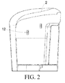
- FIG. 2 is a schematic diagram of an installation surface of the water tank and the dispenser body in FIG. 1
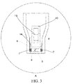
- FIG. 3 is an enlarged schematic diagram of the A region in FIG. 1 , as shown in FIG. 1 , FIG. 2 and FIG. 3 :
- the beverage dispenser includes a dispenser body 1, a water tank 2, a control device 3 used for controlling the beverage dispenser to operate and a water volume detection device 4, the water volume detection device 4 including: a substrate 5 located on the dispenser body; a mobile plate 6 that supports the water tank; an elastic element 7 disposed between the substrate 5 and the mobile plate 6; a first contact member 8 disposed below the mobile plate 6; and a second contact member 9 disposed above the substrate 5; wherein the mobile plate 6 is disposed above the substrate 5 and moves up and down relative to the substrate 5 with changes of water levels in the water tank 2, and the first contact member 8 and the second contact member 9 constitute a switch of the control device.
- the mobile plate 6, under the gravity of the water tank, is pressed to a lower side, and at this point, the first contact member 8 comes into contact with the second contact member 9, and the control device 3 starts to operate.
- the mobile plate 6, under the action of the elastic element 7, is pushed to an upper side, and at this point, the first contact member 8 does not contact the second contact member 8, and the control device 3 stops operating.
- the weight of the water tank and the coefficient of the elastic element determine displacement of the mobile plate; as the coefficient of the elastic element is definite, when the water volume changes, the displacement of the mobile plate may change correspondingly, and the values can be set through calculation.
- control device 3 when the first contact member 8 comes into contact with the second contact member 9, the control device 3 begins to operate; and when the first contact member 8 is detached from the second contact member 9, the control device 3 stops operating.
- the control device 3 includes a control circuit connected with the first contact member 8 and the second contact member 9, to form a complete circuit, and when the first contact member 8 comes into contact with or is detached from the second contact member 9, the corresponding control circuit is turned on or off.
- the first contact member 8 is a conducting strip integrally formed with the mobile plate 6, and the second contact member 9 is a conductive element extending towards the direction of the mobile plate 6.
- the first contact member 8 is set as a conducting strip, which can be integrally casted with the mobile plate 6, thus saving the space.
- the second contact member 9 is set as a conductive element extending towards the direction of the mobile plate 6, used for communicating with the first contact member 8 when the mobile plate 6 moves down.
- FIG. 4 is another schematic structural diagram of the water volume detection device; as shown in FIG. 4 , the second contact member 9 is a cylindrical object.
- the design of the water volume detection device can be flexibly selected according to a specific structure.
- the second contact member 9 is a conducting strip integrally formed with the substrate 5, and the first contact member 8 is a conductive element extending towards the direction of the substrate 5.
- the second contact member 9 is set as a conducting strip, which can be integrally casted with the substrate 5, thus saving the space.
- the first contact member 8 is set as a conductive element extending towards the direction of the substrate 5, used for communicating with the second contact member 9 when the mobile plate 6 moves down.
- the first contact member 9 is a cylindrical object or bendable sheet metal.
- the water volume detection device 4 is disposed at the bottom or on a side face of the dispenser body 1.
- the water volume detection device 4 causes the displacement of the mobile plate to change mainly by detecting the change of the gravity of the water tank, and thus the water volume detection device 4 can achieve a detection function by being disposed at the bottom of the dispenser body or on a side face of the dispenser body.
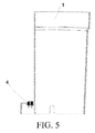
- FIG. 5 is another schematic position diagram of the water volume detection device; as shown in FIG. 5 , the water volume detection device 4 is disposed at the bottom of the dispenser body.
- the circuit system is not easily affected by steam and is much closer to a control device generally disposed on an upper portion of the dispenser body.
- a side face of the dispenser body 1 is provided thereon with a support device 10 connected with the water tank 2, wherein the support device 10 is provided thereon with a hole slot 13 matching the water tank 2 and the elastic element 7.
- the side face of the dispenser body 1 is provided with a support device 10, used for sharing the gravity of the water tank, to maintain sensitivity of the water volume detection device 4.
- a hole slot 13 is disposed on the support device 10 to match a hasp 12 on the water tank 2, used for fixing installation of the water tank 2, which can ensure that the water volume detection device 4 can be in a position of normal operation.
- an elastic element 7 is disposed, to enable the water tank 2 to displace with the change of the water volume in a state of being supported, to cooperate with the operation of the water volume detection device 4.
- the side face of the dispenser body 1 is provided thereon with at least one support device 10, wherein the water volume detection device 4 is disposed on one support device 10 therein.
- the water volume detection device 4 is disposed on the side face of the dispenser body 1, it is feasible to dispose it on the support device 10, which can ensure fixing of the water tank 2 and can also achieve water volume detection.
- the number of the support device 10 may be two or three, one of which is provided with the water volume measuring device 4, and the other two are used for fixing and sharing the gravity of the water tank, which can more ensure accuracy of water volume measurement.
- the first contact member 8 and the second contact member 9 in the water volume measuring device 4 can be removed, to form a support device 10 having an elastic element 7 and a hole slot 13, in this way, during manufacturing and production, generation of new parts is saved.
- the substrate is provided thereon with a connecting pole 14 penetrating the mobile plate.
- the connecting pole 14 By disposing the connecting pole 14, the displacement of the mobile plate relative to movement of the substrate is more stable, to ensure that relative change with the water volume is more accurate.
- the elastic element 7 in the above scheme is a spring or an elastic washer.
- the beverage dispenser further includes an alarm prompt device 15 connected with the water volume detection device 4, which is disposed on the dispenser body 1 and mainly includes a sounding device and a prompt device, used for prompting users a normal water volume state and a state of needing water of the beverage dispenser.
- an alarm prompt device 15 connected with the water volume detection device 4, which is disposed on the dispenser body 1 and mainly includes a sounding device and a prompt device, used for prompting users a normal water volume state and a state of needing water of the beverage dispenser.
- the problem in the prior art that the water volume detection device of the beverage dispenser has a high cost and is easily affected by environments, which, on the one end, reduces the manufacturing cost of the water volume detection device in the beverage dispenser, and on the other hand, causes water volume detection not to be easily affected by environments and to be more stable and accurate.
Landscapes
- Engineering & Computer Science (AREA)
- Food Science & Technology (AREA)
- Devices For Dispensing Beverages (AREA)
- Level Indicators Using A Float (AREA)
Abstract
Description
- The present invention relates to a beverage dispenser, and particularly to a water volume detection device of a beverage dispenser, mainly applied to coffee machines, juicers and the like.
- The water tank of the existing beverage dispenser is provided with a water volume detection device, used for reminding users to add water, to prevent continuous heating after water is used up. Mainly by disposing a float in the water tank and disposing a float position sensor on the dispenser body, position information of the float is detected. Specifically, when the water level in the water tank reaches a predetermined height, the height of the float changes accordingly, the float position sensor disposed outside the water tank can detect corresponding information, and thus the water level in the water tank can be monitored, so as to control the beverage dispenser and/or send a prompt when the water level in the water tank is lower than or higher than a predetermined value.
- However, the above parts such as the float and the position sensing device have a higher cost, and magnetic elements in the float are easily affected by environments, thus affecting precision of the beverage dispenser during operation.
- Therefore, an effective solution has not yet been put forward at present with respect to the problem in the prior art that the water volume detection device of the beverage dispenser has a high cost and is easily affected by environments.
- The present invention provides a beverage dispenser, to at least solve the problem in the prior art that the water volume detection device of the beverage dispenser has a high cost and is easily affected by environments.
- To achieve the objective, in one aspect of the present invention, a beverage dispenser is provided.
- A beverage dispenser according to the present invention includes a dispenser body, a water tank, a control device used for controlling the beverage dispenser to operate and a water volume detection device, the water volume detection device including: a substrate located on the dispenser body; a mobile plate that supports the water tank; an elastic element disposed between the substrate and the mobile plate; a first contact member disposed below the mobile plate; and a second contact member disposed above the substrate; wherein the mobile plate is disposed above the substrate and moves up and down relative to the substrate with changes of water levels in the water tank, and the first contact member and the second contact member constitute a switch of the control device. When the water volume reaches a set value, the mobile plate, under the gravity of the water tank, is pressed to a lower side, and at this point, the first contact member comes into contact with the second contact member, and the control device starts to operate. When the water volume does not reach the set value, the mobile plate, under the action of the elastic element, is pushed to an upper side, and at this point, the first contact member does not contact the second contact member, and the control device stops operating. The weight of the water tank and the coefficient of the elastic element determine displacement of the mobile plate; as the coefficient of the elastic element is definite, when the water volume changes, the displacement of the mobile plate may change correspondingly, and the values can be set through calculation.
- Preferably, when the first contact member comes into contact with the second contact member, the control device begins to operate; and when the first contact member is detached from the second contact member, the control device stops operating. The control device includes a control circuit connected with the first contact member and the second contact member, to form a complete circuit, and when the first contact member comes into contact with or is detached from the second contact member, the corresponding control circuit is turned on or off.
- Preferably, the first contact member is a conducting strip integrally formed with the mobile plate, and the second contact member is a conductive element extending towards the direction of the mobile plate. The first contact member is set as a conducting strip, which can be integrally casted with the mobile plate, thus saving the space. The second contact member is set as a conductive element extending towards the direction of the mobile plate, used for communicating with the first contact member when the mobile plate moves down.
- Preferably, the second contact member is a cylindrical object or bendable sheet metal.
- Preferably, the second contact member is a conducting strip integrally formed with the substrate, and the first contact member is a conductive element extending towards the direction of the substrate. The second contact member is set as a conducting strip, which can be integrally casted with the substrate, thus saving the space. The first contact member is set as a conductive element extending towards the direction of the substrate, used for communicating with the second contact member when the mobile plate moves down.
- Preferably, the first contact member is a cylindrical object or bendable sheet metal.
- Preferably, the water volume detection device is disposed at the bottom or on a side face of the dispenser body. The water volume detection device causes the displacement of the mobile plate to change mainly by detecting the change of the gravity of the water tank, and thus the water volume detection device can achieve a detection function by being disposed at the bottom of the dispenser body or on a side face of the dispenser body. Especially when the water volume detection device is disposed on the side face of the dispenser body, the control circuit is not easily affected by steam and is much closer to a control device generally disposed on an upper portion of the dispenser body.
- Preferably, a side face of the dispenser body is provided thereon with a support device connected with the water tank, wherein the support device is provided thereon with a hole slot matching the water tank and the elastic element. The side face of the dispenser body is provided with a support device, used for sharing the gravity of the water tank, to maintain sensitivity of the water volume detection device. A hole slot is disposed on the support device to match a hasp on the water tank, used for fixing installation of the water tank, which can ensure that the water volume detection device can be in a position of normal operation; meanwhile, an elastic element is disposed, to enable the water tank to displace with the change of the water volume in a state of being supported, to cooperate with the operation of the water volume detection device.
- Preferably, the side face of the dispenser body is provided thereon with at least one support device, wherein the water volume detection device is disposed on one support device therein. When the water volume detection device is disposed on the side face of the dispenser body, it is feasible to dispose it on the support device, which can ensure fixing of the water tank and can also achieve water volume detection. This depends upon the design of the weight of the water tank, and the number of the support device may be two or three, one of which is provided with the water volume measuring device, and the other two are used for fixing and sharing the gravity of the water tank, which can more ensure accuracy of water volume measurement.
- Preferably, the substrate is provided thereon with a connecting pole penetrating the mobile plate. By disposing the connecting pole, the displacement of the mobile plate relative to movement of the substrate is more stable, to ensure that relative change with the water volume is more accurate.
- Preferably, the elastic element is a spring or an elastic washer.
- Preferably, the beverage dispenser further includes an alarm prompt device connected with the water volume detection device, which is disposed on the dispenser body and mainly includes a sounding device and a prompt device, used for prompting users a normal water volume state and a state of needing water of the beverage dispenser.
- Through the present invention, the problem in the prior art that the water volume detection device of the beverage dispenser has a high cost and is easily affected by environments, which, on the one end, reduces the manufacturing cost of the water volume detection device in the beverage dispenser, and on the other hand, causes water volume detection not to be easily affected by environments and to be more stable and accurate.
- The drawings described herein are used to provide a further understanding for the present invention and constitute a part of the present application, schematic embodiments of the present invention and description thereof are used to explain the present invention and do not pose improper limitations to the present invention, and wherein:
- FIG. 1
- is a schematic structural diagram of a beverage dispenser;
- FIG. 2
- is a schematic diagram of an installation surface of the water tank and the dispenser body in
FIG. 1 ; - FIG. 3
- is an enlarged schematic diagram of the A region in
FIG. 1 ; - FIG. 4
- is another schematic structural diagram of the water volume detection device; and
- FIG. 5
- is another schematic position diagram of the water volume detection device.
- The present invention is described hereinafter in detail with reference to the accompanying drawings and in combination with embodiments. It should be noted that, without a conflict, embodiments in the present application and features in the embodiment can be combined with each other.
- In this embodiment, a beverage dispenser is provided;
FIG. 1 is a schematic structural diagram of the beverage dispenser, andFIG. 2 is a schematic diagram of an installation surface of the water tank and the dispenser body inFIG. 1 ;FIG. 3 is an enlarged schematic diagram of the A region inFIG. 1 , as shown inFIG. 1 ,FIG. 2 andFIG. 3 : - the beverage dispenser includes a
dispenser body 1, awater tank 2, acontrol device 3 used for controlling the beverage dispenser to operate and a watervolume detection device 4, the watervolume detection device 4 including: asubstrate 5 located on the dispenser body; amobile plate 6 that supports the water tank; anelastic element 7 disposed between thesubstrate 5 and themobile plate 6; afirst contact member 8 disposed below themobile plate 6; and asecond contact member 9 disposed above thesubstrate 5; wherein themobile plate 6 is disposed above thesubstrate 5 and moves up and down relative to thesubstrate 5 with changes of water levels in thewater tank 2, and thefirst contact member 8 and thesecond contact member 9 constitute a switch of the control device. - When the water volume reaches a set value, the
mobile plate 6, under the gravity of the water tank, is pressed to a lower side, and at this point, thefirst contact member 8 comes into contact with thesecond contact member 9, and thecontrol device 3 starts to operate. When the water volume does not reach the set value, themobile plate 6, under the action of theelastic element 7, is pushed to an upper side, and at this point, thefirst contact member 8 does not contact thesecond contact member 8, and thecontrol device 3 stops operating. The weight of the water tank and the coefficient of the elastic element determine displacement of the mobile plate; as the coefficient of the elastic element is definite, when the water volume changes, the displacement of the mobile plate may change correspondingly, and the values can be set through calculation. - Preferably, when the
first contact member 8 comes into contact with thesecond contact member 9, thecontrol device 3 begins to operate; and when thefirst contact member 8 is detached from thesecond contact member 9, thecontrol device 3 stops operating. Thecontrol device 3 includes a control circuit connected with thefirst contact member 8 and thesecond contact member 9, to form a complete circuit, and when thefirst contact member 8 comes into contact with or is detached from thesecond contact member 9, the corresponding control circuit is turned on or off. - Preferably, as shown in
FIG. 3 , thefirst contact member 8 is a conducting strip integrally formed with themobile plate 6, and thesecond contact member 9 is a conductive element extending towards the direction of themobile plate 6. Thefirst contact member 8 is set as a conducting strip, which can be integrally casted with themobile plate 6, thus saving the space. Thesecond contact member 9 is set as a conductive element extending towards the direction of themobile plate 6, used for communicating with thefirst contact member 8 when themobile plate 6 moves down. - Preferably, as shown in
FIG. 3 , thesecond contact member 9 in the above structure is bendable sheet metal.FIG. 4 is another schematic structural diagram of the water volume detection device; as shown inFIG. 4 , thesecond contact member 9 is a cylindrical object. The design of the water volume detection device can be flexibly selected according to a specific structure. - Preferably, in an embodiment not shown in other figures, the
second contact member 9 is a conducting strip integrally formed with thesubstrate 5, and thefirst contact member 8 is a conductive element extending towards the direction of thesubstrate 5. Thesecond contact member 9 is set as a conducting strip, which can be integrally casted with thesubstrate 5, thus saving the space. Thefirst contact member 8 is set as a conductive element extending towards the direction of thesubstrate 5, used for communicating with thesecond contact member 9 when themobile plate 6 moves down. - Preferably, the
first contact member 9 is a cylindrical object or bendable sheet metal. - Preferably, the water
volume detection device 4 is disposed at the bottom or on a side face of thedispenser body 1. The watervolume detection device 4 causes the displacement of the mobile plate to change mainly by detecting the change of the gravity of the water tank, and thus the watervolume detection device 4 can achieve a detection function by being disposed at the bottom of the dispenser body or on a side face of the dispenser body.FIG. 5 is another schematic position diagram of the water volume detection device; as shown inFIG. 5 , the watervolume detection device 4 is disposed at the bottom of the dispenser body. As shown inFIG. 1 , when the watervolume detection device 4 is disposed on the side face of the dispenser body, the circuit system is not easily affected by steam and is much closer to a control device generally disposed on an upper portion of the dispenser body. - Preferably, as shown in
FIG. 1 ,FIG. 2 andFIG. 3 , a side face of thedispenser body 1 is provided thereon with asupport device 10 connected with thewater tank 2, wherein thesupport device 10 is provided thereon with ahole slot 13 matching thewater tank 2 and theelastic element 7. The side face of thedispenser body 1 is provided with asupport device 10, used for sharing the gravity of the water tank, to maintain sensitivity of the watervolume detection device 4. Ahole slot 13 is disposed on thesupport device 10 to match ahasp 12 on thewater tank 2, used for fixing installation of thewater tank 2, which can ensure that the watervolume detection device 4 can be in a position of normal operation. Meanwhile, anelastic element 7 is disposed, to enable thewater tank 2 to displace with the change of the water volume in a state of being supported, to cooperate with the operation of the watervolume detection device 4. - Preferably, as shown in
FIG. 1 , the side face of thedispenser body 1 is provided thereon with at least onesupport device 10, wherein the watervolume detection device 4 is disposed on onesupport device 10 therein. When the watervolume detection device 4 is disposed on the side face of thedispenser body 1, it is feasible to dispose it on thesupport device 10, which can ensure fixing of thewater tank 2 and can also achieve water volume detection. This depends upon the design of the weight of thewater tank 2, and the number of thesupport device 10 may be two or three, one of which is provided with the watervolume measuring device 4, and the other two are used for fixing and sharing the gravity of the water tank, which can more ensure accuracy of water volume measurement. It is relatively convenient that thefirst contact member 8 and thesecond contact member 9 in the watervolume measuring device 4 can be removed, to form asupport device 10 having anelastic element 7 and ahole slot 13, in this way, during manufacturing and production, generation of new parts is saved. - Preferably, as shown in
FIG. 2 , the substrate is provided thereon with a connectingpole 14 penetrating the mobile plate. By disposing the connectingpole 14, the displacement of the mobile plate relative to movement of the substrate is more stable, to ensure that relative change with the water volume is more accurate. - Preferably, the
elastic element 7 in the above scheme is a spring or an elastic washer. - Preferably, as shown in
FIG. 1 , the beverage dispenser further includes an alarmprompt device 15 connected with the watervolume detection device 4, which is disposed on thedispenser body 1 and mainly includes a sounding device and a prompt device, used for prompting users a normal water volume state and a state of needing water of the beverage dispenser. - Through the present invention, the problem in the prior art that the water volume detection device of the beverage dispenser has a high cost and is easily affected by environments, which, on the one end, reduces the manufacturing cost of the water volume detection device in the beverage dispenser, and on the other hand, causes water volume detection not to be easily affected by environments and to be more stable and accurate.
- Various specific embodiments described hereinabove and shown in the drawings are merely used for describing the present invention, but not all of the present invention. Within the category of the basic technical thought of the present invention, any forms of variations made by those of ordinary skill in the art for the present invention all fall within the protection scope of the present invention.
Claims (12)
- A beverage dispenser, comprising a dispenser body (1), a water tank (2), a control device (3) used for controlling the beverage dispenser to operate and a water volume detection device (4) disposed on the dispenser body, characterized in that, the water volume detection device (4) comprises:a substrate (5) located on the dispenser body;a mobile plate (6) that supports the water tank;an elastic element (7) disposed between the substrate (5) and the mobile plate (6);a first contact member (8) disposed below the mobile plate (6); anda second contact member (9) disposed above the substrate (7); whereinthe mobile plate (6) is disposed above the substrate (5) and moves up and down relative to the substrate (5) with changes of water levels in the water tank (2), and the first contact member (8) and the second contact member (9) constitute a switch of the control device (3).
- The beverage dispenser according to claim 1, characterized in that,
when the first contact member (8) comes into contact with the second contact member (9), the control device (3) begins to operate; and when the first contact member (8) is detached from the second contact member (9), the control device (3) stops operating. - The beverage dispenser according to claim 2, characterized in that,
the first contact member (8) is a conducting strip integrally formed with the mobile plate (6), and the second contact member (9) is a conductive element extending towards the direction of the mobile plate (6). - The beverage dispenser according to claim 3, characterized in that,
the second contact member (9) is a cylindrical object or bendable sheet metal. - The beverage dispenser according to claim 2, characterized in that,
the second contact member (9) is a conducting strip integrally formed with the substrate (5), and the first contact member (8) is a conductive element extending towards the direction of the substrate (5). - The beverage dispenser according to claim 3, characterized in that,
the first contact member (8) is a cylindrical object or bendable sheet metal. - The beverage dispenser according to claim 1, characterized in that,
the water volume detection device (4) is disposed at the bottom or on a side face of the dispenser body (1). - The beverage dispenser according to claim 1, characterized in that,
a side face of the dispenser body (1) is provided thereon with a support device (10) connected with the water tank (2), wherein the support device (10) is provided thereon with a hole slot (13) matching the water tank (2) and the elastic element (7). - The beverage dispenser according to claim 8, characterized in that,
the side face of the dispenser body (1) is provided thereon with at least one support device (10), wherein the water volume detection device (4) is disposed on one support device (10) therein. - The beverage dispenser according to claim 1, characterized in that,
the substrate (5) is provided thereon with a connecting pole (14) penetrating the mobile plate (6). - The beverage dispenser according to claim 1, characterized in that,
the elastic element (7) is a spring or an elastic washer. - The beverage dispenser according to claim 1, characterized by comprising:an alarm prompt device (15) connected with the water volume detection device (4).
Applications Claiming Priority (1)
| Application Number | Priority Date | Filing Date | Title |
|---|---|---|---|
| CN201510362282.4A CN106264155A (en) | 2015-06-26 | 2015-06-26 | Beverage machine |
Publications (2)
| Publication Number | Publication Date |
|---|---|
| EP3108778A1 true EP3108778A1 (en) | 2016-12-28 |
| EP3108778B1 EP3108778B1 (en) | 2021-11-03 |
Family
ID=56235693
Family Applications (1)
| Application Number | Title | Priority Date | Filing Date |
|---|---|---|---|
| EP16176108.5A Active EP3108778B1 (en) | 2015-06-26 | 2016-06-24 | Beverage dispenser |
Country Status (2)
| Country | Link |
|---|---|
| EP (1) | EP3108778B1 (en) |
| CN (1) | CN106264155A (en) |
Cited By (2)
| Publication number | Priority date | Publication date | Assignee | Title |
|---|---|---|---|---|
| CN110801153A (en) * | 2018-08-06 | 2020-02-18 | 宁波三A集团电器有限公司 | Water shortage early warning method and system for brewing machine |
| WO2020159458A3 (en) * | 2019-01-28 | 2020-09-03 | Korkmaz Mutfak Esyalari Sanayi Ve Ticaret Anonim Sirketi | Coffee machine with water tank |
Families Citing this family (1)
| Publication number | Priority date | Publication date | Assignee | Title |
|---|---|---|---|---|
| CN108732111B (en) * | 2017-04-25 | 2022-12-13 | Bsh家用电器有限公司 | Method and quality detection device for determining the quality of at least one beverage |
Citations (2)
| Publication number | Priority date | Publication date | Assignee | Title |
|---|---|---|---|---|
| GB2140286A (en) * | 1983-04-21 | 1984-11-28 | Alfredo Cavalli | Espresso coffee machine for domestic use |
| EP2462850A1 (en) * | 2010-12-13 | 2012-06-13 | Nestec S.A. | A beverage preparation machine |
Family Cites Families (11)
| Publication number | Priority date | Publication date | Assignee | Title |
|---|---|---|---|---|
| CN2368420Y (en) * | 1999-05-13 | 2000-03-15 | 刘柄枝 | Instant water boiler |
| CN2389598Y (en) * | 1999-08-08 | 2000-08-02 | 金方吉 | Multipurpose energy-saving water-boiling heater with glass internal chamber |
| CN2891920Y (en) * | 2006-01-23 | 2007-04-25 | 吴志文 | Low center of gravity drinking water supply device |
| CN200994700Y (en) * | 2006-12-27 | 2007-12-26 | 上海市闵行中学 | Safety water drinker with automatic shutoff function |
| CN201512233U (en) * | 2009-09-27 | 2010-06-23 | 上海烟草(集团)公司 | Smoke tank with load cell |
| CN201811777U (en) * | 2010-09-30 | 2011-04-27 | 山东建设机械股份有限公司 | Admixture weighing device |
| US8977116B2 (en) * | 2011-04-05 | 2015-03-10 | Guy GONEN | Water level measurement device using load cell |
| CN102894818B (en) * | 2011-07-28 | 2014-05-14 | 罗伟林 | Tea set with water volume detecting mechanism for water tank |
| CN103479226B (en) * | 2012-06-15 | 2016-09-21 | 滁州富达机械电子有限公司 | A kind of water amount detection device of water dispenser |
| CN203249669U (en) * | 2013-04-23 | 2013-10-23 | 湖南三一路面机械有限公司 | Material level detecting device and engineering machine |
| CN203290737U (en) * | 2013-05-22 | 2013-11-20 | 杨扬 | Water dispenser equipped with weighing sensors |
-
2015
- 2015-06-26 CN CN201510362282.4A patent/CN106264155A/en active Pending
-
2016
- 2016-06-24 EP EP16176108.5A patent/EP3108778B1/en active Active
Patent Citations (2)
| Publication number | Priority date | Publication date | Assignee | Title |
|---|---|---|---|---|
| GB2140286A (en) * | 1983-04-21 | 1984-11-28 | Alfredo Cavalli | Espresso coffee machine for domestic use |
| EP2462850A1 (en) * | 2010-12-13 | 2012-06-13 | Nestec S.A. | A beverage preparation machine |
Cited By (2)
| Publication number | Priority date | Publication date | Assignee | Title |
|---|---|---|---|---|
| CN110801153A (en) * | 2018-08-06 | 2020-02-18 | 宁波三A集团电器有限公司 | Water shortage early warning method and system for brewing machine |
| WO2020159458A3 (en) * | 2019-01-28 | 2020-09-03 | Korkmaz Mutfak Esyalari Sanayi Ve Ticaret Anonim Sirketi | Coffee machine with water tank |
Also Published As
| Publication number | Publication date |
|---|---|
| EP3108778B1 (en) | 2021-11-03 |
| CN106264155A (en) | 2017-01-04 |
Similar Documents
| Publication | Publication Date | Title |
|---|---|---|
| US8960022B2 (en) | Device for detecting the presence of at least one human finger on surface, and a method of using the device in the user interface of a machine, a device (in particular a portable device), or a system | |
| JP2015529989A (en) | Capacitance sensor that detects the movement of an object | |
| CN105790747A (en) | Touch key triggering detection method and triggering detection device | |
| EP2104838B1 (en) | Discrete fluid level sensor and mount | |
| EP3108778B1 (en) | Beverage dispenser | |
| JP6050046B2 (en) | Formwork system | |
| CN104997409A (en) | Coffee machine | |
| KR20120043350A (en) | Multi liquid level sensing module | |
| EP3865830B1 (en) | Liquid level sensing systems | |
| CN220403931U (en) | Cleaning apparatus | |
| CN201364192Y (en) | Liquid level sensor | |
| CN109596189B (en) | Water tank mounting structure in household appliance and electric steam box with same | |
| CN205607493U (en) | Be provided with liquid monitoring device's movable liquid case | |
| KR101568376B1 (en) | Water level sensor and water level sensing system of apparatus using same | |
| CN105628058B (en) | Capacitance type detector, method and system | |
| CN105222856A (en) | Water level detection device and water purification equipment | |
| US20200279468A1 (en) | Method and Apparatus for Monitoring and Reporting Salt Level in a Water Softener | |
| JP2005158018A (en) | Scale using wireless tag | |
| CN215309197U (en) | Injection device | |
| CN111206393A (en) | Liquid level detection device and method, washing machine | |
| CN204839165U (en) | Coffee machine | |
| CN211212625U (en) | Electric kettle water level sensor and electric kettle | |
| JP2013164415A (en) | Salinity meter equipped with built-in impact switch | |
| CN105088677A (en) | Drum washing machine | |
| CN216645511U (en) | Liquid level monitoring device |
Legal Events
| Date | Code | Title | Description |
|---|---|---|---|
| PUAI | Public reference made under article 153(3) epc to a published international application that has entered the european phase |
Free format text: ORIGINAL CODE: 0009012 |
|
| STAA | Information on the status of an ep patent application or granted ep patent |
Free format text: STATUS: THE APPLICATION HAS BEEN PUBLISHED |
|
| AK | Designated contracting states |
Kind code of ref document: A1 Designated state(s): AL AT BE BG CH CY CZ DE DK EE ES FI FR GB GR HR HU IE IS IT LI LT LU LV MC MK MT NL NO PL PT RO RS SE SI SK SM TR |
|
| AX | Request for extension of the european patent |
Extension state: BA ME |
|
| RIN1 | Information on inventor provided before grant (corrected) |
Inventor name: XIONG, YINGJIE Inventor name: LU, PENG Inventor name: PAN, ZHIWEI |
|
| STAA | Information on the status of an ep patent application or granted ep patent |
Free format text: STATUS: REQUEST FOR EXAMINATION WAS MADE |
|
| 17P | Request for examination filed |
Effective date: 20170628 |
|
| RBV | Designated contracting states (corrected) |
Designated state(s): AL AT BE BG CH CY CZ DE DK EE ES FI FR GB GR HR HU IE IS IT LI LT LU LV MC MK MT NL NO PL PT RO RS SE SI SK SM TR |
|
| STAA | Information on the status of an ep patent application or granted ep patent |
Free format text: STATUS: EXAMINATION IS IN PROGRESS |
|
| 17Q | First examination report despatched |
Effective date: 20201030 |
|
| GRAP | Despatch of communication of intention to grant a patent |
Free format text: ORIGINAL CODE: EPIDOSNIGR1 |
|
| STAA | Information on the status of an ep patent application or granted ep patent |
Free format text: STATUS: GRANT OF PATENT IS INTENDED |
|
| INTG | Intention to grant announced |
Effective date: 20210615 |
|
| GRAS | Grant fee paid |
Free format text: ORIGINAL CODE: EPIDOSNIGR3 |
|
| GRAA | (expected) grant |
Free format text: ORIGINAL CODE: 0009210 |
|
| STAA | Information on the status of an ep patent application or granted ep patent |
Free format text: STATUS: THE PATENT HAS BEEN GRANTED |
|
| AK | Designated contracting states |
Kind code of ref document: B1 Designated state(s): AL AT BE BG CH CY CZ DE DK EE ES FI FR GB GR HR HU IE IS IT LI LT LU LV MC MK MT NL NO PL PT RO RS SE SI SK SM TR |
|
| REG | Reference to a national code |
Ref country code: GB Ref legal event code: FG4D |
|
| REG | Reference to a national code |
Ref country code: AT Ref legal event code: REF Ref document number: 1443207 Country of ref document: AT Kind code of ref document: T Effective date: 20211115 Ref country code: CH Ref legal event code: EP |
|
| REG | Reference to a national code |
Ref country code: DE Ref legal event code: R096 Ref document number: 602016065649 Country of ref document: DE |
|
| REG | Reference to a national code |
Ref country code: IE Ref legal event code: FG4D |
|
| REG | Reference to a national code |
Ref country code: LT Ref legal event code: MG9D |
|
| REG | Reference to a national code |
Ref country code: NL Ref legal event code: MP Effective date: 20211103 |
|
| REG | Reference to a national code |
Ref country code: AT Ref legal event code: MK05 Ref document number: 1443207 Country of ref document: AT Kind code of ref document: T Effective date: 20211103 |
|
| PG25 | Lapsed in a contracting state [announced via postgrant information from national office to epo] |
Ref country code: RS Free format text: LAPSE BECAUSE OF FAILURE TO SUBMIT A TRANSLATION OF THE DESCRIPTION OR TO PAY THE FEE WITHIN THE PRESCRIBED TIME-LIMIT Effective date: 20211103 Ref country code: LT Free format text: LAPSE BECAUSE OF FAILURE TO SUBMIT A TRANSLATION OF THE DESCRIPTION OR TO PAY THE FEE WITHIN THE PRESCRIBED TIME-LIMIT Effective date: 20211103 Ref country code: FI Free format text: LAPSE BECAUSE OF FAILURE TO SUBMIT A TRANSLATION OF THE DESCRIPTION OR TO PAY THE FEE WITHIN THE PRESCRIBED TIME-LIMIT Effective date: 20211103 Ref country code: BG Free format text: LAPSE BECAUSE OF FAILURE TO SUBMIT A TRANSLATION OF THE DESCRIPTION OR TO PAY THE FEE WITHIN THE PRESCRIBED TIME-LIMIT Effective date: 20220203 Ref country code: AT Free format text: LAPSE BECAUSE OF FAILURE TO SUBMIT A TRANSLATION OF THE DESCRIPTION OR TO PAY THE FEE WITHIN THE PRESCRIBED TIME-LIMIT Effective date: 20211103 |
|
| PG25 | Lapsed in a contracting state [announced via postgrant information from national office to epo] |
Ref country code: IS Free format text: LAPSE BECAUSE OF FAILURE TO SUBMIT A TRANSLATION OF THE DESCRIPTION OR TO PAY THE FEE WITHIN THE PRESCRIBED TIME-LIMIT Effective date: 20220303 Ref country code: SE Free format text: LAPSE BECAUSE OF FAILURE TO SUBMIT A TRANSLATION OF THE DESCRIPTION OR TO PAY THE FEE WITHIN THE PRESCRIBED TIME-LIMIT Effective date: 20211103 Ref country code: PT Free format text: LAPSE BECAUSE OF FAILURE TO SUBMIT A TRANSLATION OF THE DESCRIPTION OR TO PAY THE FEE WITHIN THE PRESCRIBED TIME-LIMIT Effective date: 20220303 Ref country code: PL Free format text: LAPSE BECAUSE OF FAILURE TO SUBMIT A TRANSLATION OF THE DESCRIPTION OR TO PAY THE FEE WITHIN THE PRESCRIBED TIME-LIMIT Effective date: 20211103 Ref country code: NO Free format text: LAPSE BECAUSE OF FAILURE TO SUBMIT A TRANSLATION OF THE DESCRIPTION OR TO PAY THE FEE WITHIN THE PRESCRIBED TIME-LIMIT Effective date: 20220203 Ref country code: NL Free format text: LAPSE BECAUSE OF FAILURE TO SUBMIT A TRANSLATION OF THE DESCRIPTION OR TO PAY THE FEE WITHIN THE PRESCRIBED TIME-LIMIT Effective date: 20211103 Ref country code: LV Free format text: LAPSE BECAUSE OF FAILURE TO SUBMIT A TRANSLATION OF THE DESCRIPTION OR TO PAY THE FEE WITHIN THE PRESCRIBED TIME-LIMIT Effective date: 20211103 Ref country code: HR Free format text: LAPSE BECAUSE OF FAILURE TO SUBMIT A TRANSLATION OF THE DESCRIPTION OR TO PAY THE FEE WITHIN THE PRESCRIBED TIME-LIMIT Effective date: 20211103 Ref country code: GR Free format text: LAPSE BECAUSE OF FAILURE TO SUBMIT A TRANSLATION OF THE DESCRIPTION OR TO PAY THE FEE WITHIN THE PRESCRIBED TIME-LIMIT Effective date: 20220204 Ref country code: ES Free format text: LAPSE BECAUSE OF FAILURE TO SUBMIT A TRANSLATION OF THE DESCRIPTION OR TO PAY THE FEE WITHIN THE PRESCRIBED TIME-LIMIT Effective date: 20211103 |
|
| PG25 | Lapsed in a contracting state [announced via postgrant information from national office to epo] |
Ref country code: SM Free format text: LAPSE BECAUSE OF FAILURE TO SUBMIT A TRANSLATION OF THE DESCRIPTION OR TO PAY THE FEE WITHIN THE PRESCRIBED TIME-LIMIT Effective date: 20211103 Ref country code: SK Free format text: LAPSE BECAUSE OF FAILURE TO SUBMIT A TRANSLATION OF THE DESCRIPTION OR TO PAY THE FEE WITHIN THE PRESCRIBED TIME-LIMIT Effective date: 20211103 Ref country code: RO Free format text: LAPSE BECAUSE OF FAILURE TO SUBMIT A TRANSLATION OF THE DESCRIPTION OR TO PAY THE FEE WITHIN THE PRESCRIBED TIME-LIMIT Effective date: 20211103 Ref country code: EE Free format text: LAPSE BECAUSE OF FAILURE TO SUBMIT A TRANSLATION OF THE DESCRIPTION OR TO PAY THE FEE WITHIN THE PRESCRIBED TIME-LIMIT Effective date: 20211103 Ref country code: DK Free format text: LAPSE BECAUSE OF FAILURE TO SUBMIT A TRANSLATION OF THE DESCRIPTION OR TO PAY THE FEE WITHIN THE PRESCRIBED TIME-LIMIT Effective date: 20211103 Ref country code: CZ Free format text: LAPSE BECAUSE OF FAILURE TO SUBMIT A TRANSLATION OF THE DESCRIPTION OR TO PAY THE FEE WITHIN THE PRESCRIBED TIME-LIMIT Effective date: 20211103 |
|
| REG | Reference to a national code |
Ref country code: DE Ref legal event code: R097 Ref document number: 602016065649 Country of ref document: DE |
|
| PLBE | No opposition filed within time limit |
Free format text: ORIGINAL CODE: 0009261 |
|
| STAA | Information on the status of an ep patent application or granted ep patent |
Free format text: STATUS: NO OPPOSITION FILED WITHIN TIME LIMIT |
|
| 26N | No opposition filed |
Effective date: 20220804 |
|
| PG25 | Lapsed in a contracting state [announced via postgrant information from national office to epo] |
Ref country code: AL Free format text: LAPSE BECAUSE OF FAILURE TO SUBMIT A TRANSLATION OF THE DESCRIPTION OR TO PAY THE FEE WITHIN THE PRESCRIBED TIME-LIMIT Effective date: 20211103 |
|
| PG25 | Lapsed in a contracting state [announced via postgrant information from national office to epo] |
Ref country code: SI Free format text: LAPSE BECAUSE OF FAILURE TO SUBMIT A TRANSLATION OF THE DESCRIPTION OR TO PAY THE FEE WITHIN THE PRESCRIBED TIME-LIMIT Effective date: 20211103 |
|
| PG25 | Lapsed in a contracting state [announced via postgrant information from national office to epo] |
Ref country code: MC Free format text: LAPSE BECAUSE OF FAILURE TO SUBMIT A TRANSLATION OF THE DESCRIPTION OR TO PAY THE FEE WITHIN THE PRESCRIBED TIME-LIMIT Effective date: 20211103 |
|
| REG | Reference to a national code |
Ref country code: CH Ref legal event code: PL |
|
| REG | Reference to a national code |
Ref country code: BE Ref legal event code: MM Effective date: 20220630 |
|
| PG25 | Lapsed in a contracting state [announced via postgrant information from national office to epo] |
Ref country code: LU Free format text: LAPSE BECAUSE OF NON-PAYMENT OF DUE FEES Effective date: 20220624 Ref country code: LI Free format text: LAPSE BECAUSE OF NON-PAYMENT OF DUE FEES Effective date: 20220630 Ref country code: IE Free format text: LAPSE BECAUSE OF NON-PAYMENT OF DUE FEES Effective date: 20220624 Ref country code: CH Free format text: LAPSE BECAUSE OF NON-PAYMENT OF DUE FEES Effective date: 20220630 |
|
| PG25 | Lapsed in a contracting state [announced via postgrant information from national office to epo] |
Ref country code: IT Free format text: LAPSE BECAUSE OF FAILURE TO SUBMIT A TRANSLATION OF THE DESCRIPTION OR TO PAY THE FEE WITHIN THE PRESCRIBED TIME-LIMIT Effective date: 20211103 Ref country code: BE Free format text: LAPSE BECAUSE OF NON-PAYMENT OF DUE FEES Effective date: 20220630 |
|
| PG25 | Lapsed in a contracting state [announced via postgrant information from national office to epo] |
Ref country code: HU Free format text: LAPSE BECAUSE OF FAILURE TO SUBMIT A TRANSLATION OF THE DESCRIPTION OR TO PAY THE FEE WITHIN THE PRESCRIBED TIME-LIMIT; INVALID AB INITIO Effective date: 20160624 |
|
| PG25 | Lapsed in a contracting state [announced via postgrant information from national office to epo] |
Ref country code: MK Free format text: LAPSE BECAUSE OF FAILURE TO SUBMIT A TRANSLATION OF THE DESCRIPTION OR TO PAY THE FEE WITHIN THE PRESCRIBED TIME-LIMIT Effective date: 20211103 Ref country code: CY Free format text: LAPSE BECAUSE OF FAILURE TO SUBMIT A TRANSLATION OF THE DESCRIPTION OR TO PAY THE FEE WITHIN THE PRESCRIBED TIME-LIMIT Effective date: 20211103 |
|
| PG25 | Lapsed in a contracting state [announced via postgrant information from national office to epo] |
Ref country code: MT Free format text: LAPSE BECAUSE OF FAILURE TO SUBMIT A TRANSLATION OF THE DESCRIPTION OR TO PAY THE FEE WITHIN THE PRESCRIBED TIME-LIMIT Effective date: 20211103 |
|
| PGFP | Annual fee paid to national office [announced via postgrant information from national office to epo] |
Ref country code: DE Payment date: 20250630 Year of fee payment: 10 |
|
| PGFP | Annual fee paid to national office [announced via postgrant information from national office to epo] |
Ref country code: GB Payment date: 20250620 Year of fee payment: 10 |
|
| PGFP | Annual fee paid to national office [announced via postgrant information from national office to epo] |
Ref country code: FR Payment date: 20250624 Year of fee payment: 10 |
|
| PG25 | Lapsed in a contracting state [announced via postgrant information from national office to epo] |
Ref country code: TR Free format text: LAPSE BECAUSE OF FAILURE TO SUBMIT A TRANSLATION OF THE DESCRIPTION OR TO PAY THE FEE WITHIN THE PRESCRIBED TIME-LIMIT Effective date: 20211103 |