EP3108150B1 - Ausfalldetektion für zug-druck-stangen mit reservelastpfad - Google Patents
Ausfalldetektion für zug-druck-stangen mit reservelastpfad Download PDFInfo
- Publication number
- EP3108150B1 EP3108150B1 EP15716713.1A EP15716713A EP3108150B1 EP 3108150 B1 EP3108150 B1 EP 3108150B1 EP 15716713 A EP15716713 A EP 15716713A EP 3108150 B1 EP3108150 B1 EP 3108150B1
- Authority
- EP
- European Patent Office
- Prior art keywords
- push
- load path
- pull rod
- hole
- tubular body
- Prior art date
- Legal status (The legal status is an assumption and is not a legal conclusion. Google has not performed a legal analysis and makes no representation as to the accuracy of the status listed.)
- Active
Links
Images

Classifications
-
- F—MECHANICAL ENGINEERING; LIGHTING; HEATING; WEAPONS; BLASTING
- F16—ENGINEERING ELEMENTS AND UNITS; GENERAL MEASURES FOR PRODUCING AND MAINTAINING EFFECTIVE FUNCTIONING OF MACHINES OR INSTALLATIONS; THERMAL INSULATION IN GENERAL
- F16C—SHAFTS; FLEXIBLE SHAFTS; ELEMENTS OR CRANKSHAFT MECHANISMS; ROTARY BODIES OTHER THAN GEARING ELEMENTS; BEARINGS
- F16C7/00—Connecting-rods or like links pivoted at both ends; Construction of connecting-rod heads
- F16C7/02—Constructions of connecting-rods with constant length
-
- F—MECHANICAL ENGINEERING; LIGHTING; HEATING; WEAPONS; BLASTING
- F16—ENGINEERING ELEMENTS AND UNITS; GENERAL MEASURES FOR PRODUCING AND MAINTAINING EFFECTIVE FUNCTIONING OF MACHINES OR INSTALLATIONS; THERMAL INSULATION IN GENERAL
- F16C—SHAFTS; FLEXIBLE SHAFTS; ELEMENTS OR CRANKSHAFT MECHANISMS; ROTARY BODIES OTHER THAN GEARING ELEMENTS; BEARINGS
- F16C7/00—Connecting-rods or like links pivoted at both ends; Construction of connecting-rod heads
- F16C7/02—Constructions of connecting-rods with constant length
- F16C7/026—Constructions of connecting-rods with constant length made of fibre reinforced resin
-
- F—MECHANICAL ENGINEERING; LIGHTING; HEATING; WEAPONS; BLASTING
- F16—ENGINEERING ELEMENTS AND UNITS; GENERAL MEASURES FOR PRODUCING AND MAINTAINING EFFECTIVE FUNCTIONING OF MACHINES OR INSTALLATIONS; THERMAL INSULATION IN GENERAL
- F16C—SHAFTS; FLEXIBLE SHAFTS; ELEMENTS OR CRANKSHAFT MECHANISMS; ROTARY BODIES OTHER THAN GEARING ELEMENTS; BEARINGS
- F16C7/00—Connecting-rods or like links pivoted at both ends; Construction of connecting-rod heads
-
- F—MECHANICAL ENGINEERING; LIGHTING; HEATING; WEAPONS; BLASTING
- F16—ENGINEERING ELEMENTS AND UNITS; GENERAL MEASURES FOR PRODUCING AND MAINTAINING EFFECTIVE FUNCTIONING OF MACHINES OR INSTALLATIONS; THERMAL INSULATION IN GENERAL
- F16C—SHAFTS; FLEXIBLE SHAFTS; ELEMENTS OR CRANKSHAFT MECHANISMS; ROTARY BODIES OTHER THAN GEARING ELEMENTS; BEARINGS
- F16C2204/00—Metallic materials; Alloys
- F16C2204/40—Alloys based on refractory metals
- F16C2204/42—Alloys based on titanium
-
- F—MECHANICAL ENGINEERING; LIGHTING; HEATING; WEAPONS; BLASTING
- F16—ENGINEERING ELEMENTS AND UNITS; GENERAL MEASURES FOR PRODUCING AND MAINTAINING EFFECTIVE FUNCTIONING OF MACHINES OR INSTALLATIONS; THERMAL INSULATION IN GENERAL
- F16C—SHAFTS; FLEXIBLE SHAFTS; ELEMENTS OR CRANKSHAFT MECHANISMS; ROTARY BODIES OTHER THAN GEARING ELEMENTS; BEARINGS
- F16C2326/00—Articles relating to transporting
- F16C2326/43—Aeroplanes; Helicopters
Definitions
- Fail-safe in this context means that at least two equivalent systems are present in the component concerned, which can fulfill the specified task of the component, whereby only one of the two systems may act. If the first system fails, its function must be automatically adopted by the second system. It is particularly important that the failure of the first system can be automatically detected and corrected by the component.
- the object of the invention is therefore to provide an on the one hand trouble-free and fail-safe train-pressure rod with initially ineffective reserve system available that automatically recognizes damage or malfunction, independently fixes and on the other hand the failover by the reserve system clearly and easily recognizable so that it can be monitored and replaced as needed during routine routine maintenance with minimal effort and time.
- the train push rod Since, of course, according to the logic of reliability, this can only be achieved if only a defined load path receives the loads, the train push rod must be constructed so that it has two separate working load paths, which are so related to each other, that only one load path receives the power transmission and takes over this task only in case of failure of the first load path of the second load path.
- Under load path in the context of the invention is to be understood as the entirety of the individual parts of the train-pressure rod, which are intended to absorb the forces acting on them. These are the tubular body and the two-sided body-mounted fork ends.
- the aim of the invention namely on the one hand to ensure the reliability by automatic detection of damage and their automatic correction and on the other hand to make the failure of the first system from the outside, is achieved in that tubular body and both forks get a bivalve (two-layer) structure.
- Both shells (layers) can be made of the same common materials as light metal, titanium or carbon fiber reinforced plastic.
- the arrangement of the two shells or layers has to be such that the layer forming the load path 1 is arranged inside in the fork, but outside in the tube body, whereas in the layer forming the load path 2 (component 2) the situation is exactly the opposite,
- the outer layer forming the load path 2 in the fork separates the layer of the load path 1 (component 1) inside the fork from the layer of the load path 1 (component 1) lying in the tube in the transition region between pipe and fork.
- This arrangement is chosen so that the choice of the inside of the fork for the load path 1 is clearly detectable in case of failure. The same applies to the choice of the outside of the tubular body for the load path. 1
- the use of the load path 2 (component 2) is now accomplished by the system as follows. Due to the loss of power by the Load path 1 (component 1) shifts under the force F on the bore 7 of the component 1 relative to the component 2. The shift is completed when the diameter of the bore 7 has reached the diameter of the bore 8 with the result that now only the Component 2, so the load path 2 by the non-positive contact with the bore 8 receives the force.
- control bore 3 is designed as a sleeve with a very small wall thickness. Furthermore, it must be made of a very ductile material (such as titanium grade 1 or austenitic stainless steel) with low strength. This ensures that even under slight force F, a permanent deformation of the control bore 3 that is detectable from the outside by a test device is produced.
- a very ductile material such as titanium grade 1 or austenitic stainless steel
Landscapes
- Engineering & Computer Science (AREA)
- General Engineering & Computer Science (AREA)
- Mechanical Engineering (AREA)
- Force Measurement Appropriate To Specific Purposes (AREA)
- Investigating Strength Of Materials By Application Of Mechanical Stress (AREA)
- Shafts, Cranks, Connecting Bars, And Related Bearings (AREA)
- Vibration Dampers (AREA)
- Investigation Of Foundation Soil And Reinforcement Of Foundation Soil By Compacting Or Drainage (AREA)
- Load-Engaging Elements For Cranes (AREA)
- Forklifts And Lifting Vehicles (AREA)
- Testing Of Devices, Machine Parts, Or Other Structures Thereof (AREA)
Description
- Im Flugzeugbau werden für die verschiedensten Anwendungen in den sicherheitsrelevanten Bereichen, insbesondere in den Flügeln, Bauteile benötigt, die störungsfrei und ausfallsicher bzw. die im Falle von Schäden über Ersatzvorrichtungen verfügen, die den Ausfall des beschädigten Teils des Bauteils selbsterkennend, automatisch und sicher ersetzen, d.h. deren Funktion nach dem "Fail-safe"-Prinzip ausgelegt sein muss. "Fail-safe" bedeutet in diesem Zusammenhang, dass im betreffenden Bauteil mindestens zwei gleichwertige Systeme vorhanden sind, die die vorgegebene Aufgabe des Bauteils erfüllen können, wobei immer nur eines der beiden Systeme wirken darf. Fällt das erste System aus, muss seine Funktion automatisch vom zweiten System gleichwertig übernommen werden. Hierbei ist besonders wichtig, dass der Ausfall des ersten Systems selbsttätig vom Bauteil festgestellt und behoben werden kann.
Diese Anforderungen gelten insbesondere für die im Flugzeugbau umfangreich zum Einsatz kommenden Zug-Druck-Stangen, die aufgrund der starken und häufig wechselnden Belastungen besonders beansprucht werden, sodass Totalausfälle durch Materialermüdung oder Überlast ausgeschlossen werden müssen.
Derzeit wird diesen Anforderungen dadurch begegnet, dass bei häufigen Wartungsintervallen vorsorglich die Zug-Druck-Stangen mit einer bestimmten Einsatzdauer routinemäßig ausgetauscht bzw. ausgebaut, zerlegt, geprüft, erneut zusammengesetzt und wieder eingebaut werden, was aber naturgemäß mit einem erheblichen Zeit- und Kostenaufwand verbunden ist.
Die besonders im Flugzeugbau üblichen Zug-Druck-Stangen sind in verschiedenen Variationen bekannt, so beispielsweise ausDE 202004016321 U . In der Regel besitzen diese rohrförmigen einschalige Körper aus Leichtmetall, Titan oder karbonfaserverstärktem Kunststoff, die an beiden Enden mit je einer einschichtigen Gabel oder Auge aus Leichtmetall versehen ist. Aus derEP 2 607 229 ist auch eine zweischalig aufgebaute Zug-Druck-Stange bekannt. Die Aufgabe der Erfindung ist es daher, eine einerseits störungsfreie und ausfallsichere Zug-Druck-Stange mit zunächst nicht wirksamen Reservesystem zur Verfügung zu stellen, die Beschädigungen bzw. Funktionsausfälle selbsttätig erkennt, eigenständig behebt und andererseits die Funktionsübernahme durch das Reservesystem eindeutig und leicht erkennbar anzeigt, sodass sie bei den routinemäßigen Kontrollwartungen mit geringem Aufwand an Zeit und Kosten auf Ihre Funktion kontrolliert und bei Bedarf ersetzt werden kann. Diese Aufgabe wurde wie folgt gelöst. - Da naturgemäß nach der Logik der Ausfallsicherheit diese nur erreicht werden kann, wenn jeweils nur ein definierter Lastpfad die Lasten aufnimmt, muss die Zug-Druckstange so aufgebaut sein, dass diese zwei voneinander getrennt arbeitende Lastpfade aufweist, die so zu einander in Bezug gesetzt werden, dass jeweils nur ein Lastpfad die Kraftübertragung aufnimmt und nur bei Ausfall des ersten Lastpfades der zweite Lastpfad diese Aufgabe übernimmt. Unter Lastpfad im Sinne der Erfindung ist dabei die Gesamtheit der Einzelteile der Zug-Druck-Stange zu verstehen, die dazu bestimmt sind, die auf diese einwirkenden Kräfte aufzunehmen. Diese sind der rohrförmige Körper und die beidseitigen am Körper angebrachten Gabelenden.
- Das Ziel der Erfindung, nämlich einerseits die Ausfallsicherheit durch selbsttätiges Erkennen der Beschädigung und deren selbsttätige Behebung zu gewährleisten und andererseits den Ausfall des ersten Systems von außen detektierbar zu machen, wird dadurch erreicht, dass Rohrkörper und beide Gabeln einen zweischaligen (zweischichtigen) Aufbau erhalten. Beide Schalen (Schichten) können aus denselben üblichen Werkstoffen wie Leichtmetall, Titan oder karbonfaserverstärktem Kunststoff gefertigt werden. Die Anordnung der beiden Schalen bzw. Schichten hat so zu erfolgen, dass die den Lastpfad 1 bildende Schicht in der Gabel innen, im Rohrkörper aber außen angeordnet wird, während es sich bei der den Lastpfad 2 (Bauteil 2) bildenden Schicht genau umgekehrt verhält, Dabei trennt die in der Gabel außen liegende, den Lastpfad 2 bildende Schicht im Übergangsbereich zwischen Rohr und Gabel die in der Gabel innen liegende Schicht des Lastpfads 1 (Bauteil 1) von der im Rohr außen liegenden Schicht des Lastpfads 1 (Bauteil 1). Diese Anordnung ist so gewählt, da durch die Wahl der Innenseite der Gabel für den Lastpfad 1 dieser bei Versagen eindeutig detektierbar ist. Das gleiche gilt für die Wahl der Außenseite des Rohrkörpers für den Lastpfad 1.
- Um zu gewährleisten, dass immer nur ein Lastpfad zum Einsatz kommt, muss die Anbindung der Kraftübertragung wie folgt ausgeführt werden. In beiden Gabeln und im Rohrkörper der Zug-Druck-Stange sind jeweils auf beiden Seiten diagonal je eine Bohrung D1 (7) und D2 (8) durch die Lastpfade 1 und 2 (Bauteile 1 und 2) angebracht, durch die beidseitig je ein Bolzen 9 führt, der der Kraftübertragung dient und dessen Stärke von der zu erwartenden Belastung abhängig ist. Die Bohrung 7 wird dabei mit geringfügig kleinerem Durchmesser (ca. 0,5-1mm) als die Bohrung 8 ausgeführt, sodass die auftretenden Kräfte zunächst nur über die Bohrung 7 mit dem kleineren Durchmesser durch den kraftschlüssigen Kontakt auf den Lastpfad 1 (Bauteil 1) übertragen werden. Dieser Aufbau ist zwingend erforderlich, da nur so die Erkennung (Detektion) des eventuell später eintretenden Ausfalls des ersten Lastpfades (Bauteil 1) möglich ist und gleichzeitig der (Reserve) Lastpfad 2 (Bauteil 2) zunächst nicht belastet wird.
- Nach der selbsttätigen Detektion des Ausfalls des Lastpfades 1 (Bauteil 1) infolge Beschädigung wird nun der Einsatz des Lastpfades 2 (Bauteil 2) wie folgt vom System von sich aus bewerkstelligt. Durch den Ausfall der Kraftaufnahme durch den Lastpfad 1 (Bauteil 1) verschiebt sich unter der Krafteinwirkung F auf die Bohrung 7 der Bauteil 1 gegenüber dem Bauteil 2. Die Verschiebung ist beendet sobald der Durchmesser der Bohrung 7 den Durchmesser der Bohrung 8 erreicht hat mit dem Ergebnis, dass nunmehr nur noch der Bauteil 2, also der Lastpfad 2 durch den kraftschlüssigen Kontakt mit der Bohrung 8 die Kraft aufnimmt.
- Weiterer wesentlicher Teil der Erfindung ist nun, dass bei den regelmäßig stattfindenden Kontrollwartungen der Ausfall des Bauteils bzw. Lastpfades 1 durch den Wartungstechniker ebenfalls erkannt bzw. detektiert werden kann, damit der dann notwendige Austausch vorgenommen wird. Dies geschieht auf überraschend einfache Weise mittels der Kontrollbohrung 3 mit einem Durchmesser von ca 4-6mm und mit Hilfe des Prüfdorns 4, der zwingend zum Werkzeug des Wartungstechnikers gehört. Durch die Verschiebung des Bauteils 1 gegenüber dem Bauteil 2 wird durch die Krafteinwirkung F die Kontrollbohrung 3 so deformiert, dass der im unbeschädigten Zustand der Kontrollbohrung passgenaue Prüfdorn 4 durch den Wartungstechniker wegen der irreversiblen Verformung nicht mehr in die Kontrollbohrung 3 der Bauteile 1 und 2 eindringen kann.
- Voraussetzung hierfür ist, dass die Kontrollbohrung 3 als Hülse mit sehr geringer Wandstärke ausgeführt ist. Des Weiteren muss diese aus einem sehr duktilen Werkstoff (wie Titan Grad 1 oder austenitischer Edelstahl) mit geringer Festigkeit bestehen. Somit ist sichergestellt, dass schon unter geringer Krafteinwirkung F eine bleibende und damit von außen durch ein Prüfgerät detektierbare Verformung der Kontrollbohrung 3 entsteht.
- So kann der Ausfall des Lastpfades 1 bei der Wartung von außen eindeutig detektiert und der Austausch der Zug-Druck-Stange wegen Ausfall des Lastpfades 1 veranlasst werden.
- Die Erfindung wird nachfolgend anhand eines bevorzugten Ausführungsbeispiels näher erläutert.
-
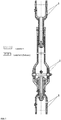
Abbildung 1 zeigt eine komplette Zug-Druck-Stange, bestehend aus dem Rohrkörper 5 und den Gabeln 6, diese wiederum bestehend aus den Bauteilen 1 und 2, die jeweils den Lastpfad 1 bzw. Lastpfad 2 bilden. Zur leichteren Erkennbarkeit sind die Bauteile des Lastpfades 1 in Gabel und Rohrkörper schräg schraffiert, diejenigen des Lastpfades 2 kreuzweise schraffiert. - Die
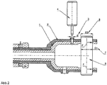
Abbildung 2 zeigt die Gabel 6 mit der Bohrung D1 (7) sowie der Bohrung D2 (8) zusammen mit dem kraftübertragenden Bolzen 9, der mit der Bohrung D1 (7) vorzugsweise über eine Spielpassung kraftschlüssig verbunden ist. Hierbei ist die Bohrung D1 (7) geringfügig kleiner ausgebildet als die Bohrung D2 (8). Ferner zeigt dieAbbildung 2 die Kontrollbohrung 3, die dazu dient, die Beschädigung des Bauteils 1 und damit den Ausfall des Lastpfades 1 anzuzeigen. - Die
Abbildung 3 zeigt den Aufbau des Rohrkörpers 5, zusammen mit der Bohrung D1 (7) die ebenfalls einen geringfügig geringeren Durchmesser aufweist als die Bohrung D2 (8), allerdings mit der Maßgabe, dass nunmehr das Bauteil 1 (Lastpfad 1) außen und das Bauteil 2 (Lastpfad 2) innen liegen. Ferner zeigt dieAbbildung 3 die Kontrollbohrung 3, die dazu dient, die Beschädigung des Bauteils 1 und damit den Ausfall des Lastpfades 1 anzuzeigen. -
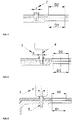
Abbildung 4 zeigt die Kontrollbohrung 3 im Zustand der Beschädigung. Hierbei ist nun durch den Ausfall des Lastpfades 1 die Bohrung D1 auf die Bohrung D2 verschoben worden. Dies bewirkt die bleibende Deformation der Kontrollbohrung 3. -
Abbildung 5 zeigt die Kontrollbohrung 3 im Zustand der Beschädigung zusammen mit dem Prüfdorns 4 während der Kontrolle. Hier ist nun zu sehen, dass der Prüfdorns 4 nicht mehr in die Kontrollbohrung 3 eingeführt werden kann. Somit ist der Ausfall des Lastpfades 1 eindeutig detektiert. -
Abbildung 6 zeigt die Kontrollbohrung 3 im unbeschädigten Zustand. Hier kann der Prüfdorns 4 bis zum Anschlag in die Kontrollbohrung 3 eingeführt werden. Somit ist sichergestellt, dass der Lastpfades 1 keine Beschädigung aufweist. -
- 1. Bauteil 1 (Lastpfad 1)
- 2. Bauteil 2 (Lastpfad 2)
- 3. Kontrollbohrung
- 4. Prüfdorn
- 5. Rohrkörper
- 6. Gabel
- 7. Bohrung D 1
- 8. Bohrung D 2
- 9. Bolzen der Bohrung D 1/D2
Claims (5)
- Zweischalig aufgebaute Zug-Druck-Stange aus Leichtmetall, Titan oder karbonfaserverstärktem Kunststoff, bestehend aus: erster Schicht (1), die den Lastpfad 1 bildet, der in den Gabeln (6) der Zug-Druck-Stange innen und im Rohrkörper (5) außen angeordnet ist und zweiter Schicht (2), die den Lastpfad 2 bildet der in den Gabeln (6) außen und im Rohrkörper (5) innen angeordnet ist, wobei die zweite Schicht (2) im Übergangsbereich zwischen Rohrkörper (5) und Gabeln (6) die in den Gabeln(6) innen liegende erste Schicht (1) von der im Rohrkörper (5) außen liegenden ersten Schicht (1) trennt, wobei die Gabeln (6) und Rohrkörper (5) der Zug-Druck-Stange auf beiden Seiten diagonal je eine Bohrung D1 (7) und D2 (8) durch die erste und die zweite Schichten (1 und 2) der Zug-Druck-Stange enthalten, durch die Bolzen (9) zwecks Kraftübertragung führen,
dadurch gekennzeichnet, dass die Bohrung D 1 (7) einen 0,5 bis 1 mm geringeren Durchmesser als die Bohrung D 2 (8) aufweist und der Bolzen (9) im Ausgangsstadium nur kraftschlüssigen Kontakt mit der Bohrung D1 (7) hat. - Zug-Druck-Stange nach Anspruch 1 dadurch gekennzeichnet, dass zusätzlich neben den Bohrungen D1 (7) und D2 (8) im Rohrkörper (5) und in den Gabeln (6) der Zug-Druck-Stange eine Kontrollbohrung (3) durch die erste (1) und die zweite (2) Schichten als Hülse mit sehr geringer Wandstärke aus sehr duktilem Werkstoff angebracht ist und somit bei schon geringer Krafteinwirkung die Hülse irreversibel so verformt wird, dass ein passgenauer Prüfdorn (4) nicht mehr in die Kontrollbohrung (3) eingeführt werden kann.
- Zug-Druck-Stange nach Anspruch 2, dadurch gekennzeichnet, dass die Kontrollbohrung (3) einen Durchmesser von ca. 4-6 mm hat.
- Zug-Druck-Stange nach Anspruch 2, dadurch gekennzeichnet, dass die Hülse der Kontrollbohrung (3) aus Titan Grad 1 besteht.
- Zug-Druck-Stange nach Anspruch 2, dadurch gekennzeichnet, dass die Hülse der Kontrollbohrung (3) aus austenitischem Edelstahl besteht.
Applications Claiming Priority (2)
| Application Number | Priority Date | Filing Date | Title |
|---|---|---|---|
| DE202014001394.2U DE202014001394U1 (de) | 2014-02-18 | 2014-02-18 | Ausfalldetektion für Zug-Druck-Stangen mit Reservelastpfad |
| PCT/DE2015/000062 WO2015124132A1 (de) | 2014-02-18 | 2015-02-10 | Ausfalldetektion für zug-druck-stangen mit reservelastpfad |
Publications (2)
| Publication Number | Publication Date |
|---|---|
| EP3108150A1 EP3108150A1 (de) | 2016-12-28 |
| EP3108150B1 true EP3108150B1 (de) | 2018-06-06 |
Family
ID=50480145
Family Applications (1)
| Application Number | Title | Priority Date | Filing Date |
|---|---|---|---|
| EP15716713.1A Active EP3108150B1 (de) | 2014-02-18 | 2015-02-10 | Ausfalldetektion für zug-druck-stangen mit reservelastpfad |
Country Status (8)
| Country | Link |
|---|---|
| US (1) | US10267351B2 (de) |
| EP (1) | EP3108150B1 (de) |
| JP (1) | JP6491235B2 (de) |
| BR (1) | BR112016018688B1 (de) |
| CA (1) | CA2938925C (de) |
| DE (1) | DE202014001394U1 (de) |
| RU (1) | RU2649253C2 (de) |
| WO (1) | WO2015124132A1 (de) |
Families Citing this family (2)
| Publication number | Priority date | Publication date | Assignee | Title |
|---|---|---|---|---|
| CN105364752B (zh) * | 2015-11-30 | 2017-05-10 | 高铁检测仪器(东莞)有限公司 | 箱包拉杆耐疲劳测试机夹具 |
| US11892035B2 (en) * | 2021-04-23 | 2024-02-06 | Hamilton Sundstrand Corporation | Composite/metal joints |
Family Cites Families (13)
| Publication number | Priority date | Publication date | Assignee | Title |
|---|---|---|---|---|
| FR91517E (fr) * | 1966-07-20 | 1968-06-28 | Rech S De Mecanique Appliquee | Bielle ou tige de timonerie |
| GB1485078A (en) * | 1974-09-14 | 1977-09-08 | Messerschmitt Boelkow Blohm | Connecting element for transmission of compressive or extensive loads |
| DE3111698A1 (de) * | 1981-03-25 | 1982-10-14 | Messerschmitt-Bölkow-Blohm GmbH, 8000 München | "verfahren und einrichtung zum ueberpruefen von bauteilen im bereich ueberlappender verbindungen" |
| FR2599793B1 (fr) * | 1986-06-09 | 1988-10-21 | Aerospatiale | Systeme de bielle destine a resister a un seuil d'efforts longitudinaux |
| US5203522A (en) * | 1991-07-03 | 1993-04-20 | United Technologies Corporation | Resealable protective boot |
| DE202004016321U1 (de) | 2004-10-20 | 2005-03-10 | Trigum-Engineering Gmbh | Zug-Druck-Stange |
| FR2918134B1 (fr) * | 2007-06-28 | 2009-09-18 | Eads Europ Aeronautic Defence | Bielle structurale en materiau composite et procede de realisation d'une bielle en materiau composite |
| US8161619B2 (en) * | 2007-11-02 | 2012-04-24 | The Boeing Company | Joint for hybrid composite items |
| FR2952150B1 (fr) * | 2009-11-02 | 2012-02-24 | Airbus Operations Sas | Bielle structurale comportant un mode filtrant des vibrations |
| FR2965850B1 (fr) * | 2010-10-11 | 2012-12-14 | Airbus Operations Sas | Dispositif de liaison de securite et aeronef equipe d'un tel dispositif de liaison de securite |
| FR2965867B1 (fr) * | 2010-10-12 | 2013-08-09 | Airbus Operations Sas | Bielle structurale adaptee a filtrer des vibrations longitudinales |
| ES2586211T3 (es) * | 2011-12-22 | 2016-10-13 | Airbus Operations, S.L | Vástago de material compuesto y método de fabricación |
| DE102012018554B3 (de) * | 2012-09-20 | 2014-02-13 | Audi Ag | Lenker für eine Radaufhängung eines Kraftfahrzeugs |
-
2014
- 2014-02-18 DE DE202014001394.2U patent/DE202014001394U1/de not_active Expired - Lifetime
-
2015
- 2015-02-10 BR BR112016018688-5A patent/BR112016018688B1/pt active IP Right Grant
- 2015-02-10 EP EP15716713.1A patent/EP3108150B1/de active Active
- 2015-02-10 RU RU2016134988A patent/RU2649253C2/ru active
- 2015-02-10 WO PCT/DE2015/000062 patent/WO2015124132A1/de not_active Ceased
- 2015-02-10 US US15/119,129 patent/US10267351B2/en active Active
- 2015-02-10 CA CA2938925A patent/CA2938925C/en active Active
- 2015-02-10 JP JP2016569001A patent/JP6491235B2/ja active Active
Non-Patent Citations (1)
| Title |
|---|
| None * |
Also Published As
| Publication number | Publication date |
|---|---|
| EP3108150A1 (de) | 2016-12-28 |
| US20170058941A1 (en) | 2017-03-02 |
| CA2938925C (en) | 2017-11-28 |
| WO2015124132A1 (de) | 2015-08-27 |
| BR112016018688B1 (pt) | 2022-03-08 |
| DE202014001394U1 (de) | 2014-03-24 |
| BR112016018688A2 (de) | 2017-08-08 |
| CA2938925A1 (en) | 2015-08-27 |
| JP6491235B2 (ja) | 2019-03-27 |
| US10267351B2 (en) | 2019-04-23 |
| RU2016134988A3 (de) | 2018-03-22 |
| JP2017512292A (ja) | 2017-05-18 |
| RU2016134988A (ru) | 2018-03-22 |
| RU2649253C2 (ru) | 2018-03-30 |
Similar Documents
| Publication | Publication Date | Title |
|---|---|---|
| WO2016087594A1 (de) | Rotorblatt für windkraftanlagen | |
| DE10031427C2 (de) | Käfig für ein Wälzlager | |
| DE102013214247A1 (de) | Blindnietmutter für die Verbindung zweier Bauteile | |
| EP4149721B1 (de) | Antriebseinheit für eine pressschlinge | |
| WO2020200776A1 (de) | Mehrteiliges verstellelement für eine toleranzausgleichsanordnung | |
| WO2019122023A1 (de) | Windkraftanlage, rotorsystem, verfahren zur verwendung einer windkraftanlage | |
| WO2016050952A1 (de) | Mechatronisches sicherheitssystem für fahrgeschäfte, insbesondere achterbahnen, karussells oder dergleichen | |
| EP2484924A1 (de) | Fügeverbindung sowie Verfahren zur Ausbildung einer Fügeverbindung | |
| EP3110587B1 (de) | Lötspitzenbefestigungssystem | |
| WO2017148747A1 (de) | Windkraftanlage mit verbesserter rotorblattverschraubung | |
| WO2015124132A1 (de) | Ausfalldetektion für zug-druck-stangen mit reservelastpfad | |
| EP1790437A2 (de) | Vorrichtung zum Einpressen eines auf einer Radnabe sitzenden Radlagers | |
| DE102016213811B4 (de) | Werkzeug und Verfahren zum Ein- und Ausziehen von Bauteilen | |
| DE102019108628B4 (de) | Steckverbindergehäuse | |
| EP2833007B1 (de) | Drehbare Verbindung | |
| DE3521223A1 (de) | Vorrichtung zum blockieren mit widerstand gegen eventuelle axiale belastungen von lagern oder koerpern mit rotierenden elementen an achsen oder wellen | |
| EP3926206B1 (de) | Lasche einer bolzen-, buchsen- oder rollenkette | |
| DE102016224014B4 (de) | Spannvorrichtung und Verfahren zum Einbringen einer Vorspannung in ein rohrförmiges Hohlprofil | |
| DE102018107320B4 (de) | Kraftmesseinrichtung | |
| DE102006020554A1 (de) | Verbindungsstrebe zur Anordnung zwischen benachbarten Landeklappen eines Flugzeuges | |
| DE102012001057A1 (de) | Bauteil | |
| WO2003014473A1 (de) | Fahrweg für ein spurgebundenes fahrzeug | |
| AT516493B1 (de) | Abkantpresse | |
| DE102022121315B4 (de) | Lagerbaueinheit | |
| EP2841795B1 (de) | Kraftübertragungseinheit |
Legal Events
| Date | Code | Title | Description |
|---|---|---|---|
| PUAI | Public reference made under article 153(3) epc to a published international application that has entered the european phase |
Free format text: ORIGINAL CODE: 0009012 |
|
| STAA | Information on the status of an ep patent application or granted ep patent |
Free format text: STATUS: REQUEST FOR EXAMINATION WAS MADE |
|
| 17P | Request for examination filed |
Effective date: 20160919 |
|
| AK | Designated contracting states |
Kind code of ref document: A1 Designated state(s): AL AT BE BG CH CY CZ DE DK EE ES FI FR GB GR HR HU IE IS IT LI LT LU LV MC MK MT NL NO PL PT RO RS SE SI SK SM TR |
|
| AX | Request for extension of the european patent |
Extension state: BA ME |
|
| DAX | Request for extension of the european patent (deleted) | ||
| REG | Reference to a national code |
Ref country code: DE Ref legal event code: R079 Ref document number: 502015004530 Country of ref document: DE Free format text: PREVIOUS MAIN CLASS: F16C0007000000 Ipc: F16C0007020000 |
|
| RIC1 | Information provided on ipc code assigned before grant |
Ipc: F16C 7/02 20060101AFI20171129BHEP Ipc: F16C 7/00 20060101ALI20171129BHEP |
|
| GRAP | Despatch of communication of intention to grant a patent |
Free format text: ORIGINAL CODE: EPIDOSNIGR1 |
|
| STAA | Information on the status of an ep patent application or granted ep patent |
Free format text: STATUS: GRANT OF PATENT IS INTENDED |
|
| INTG | Intention to grant announced |
Effective date: 20180109 |
|
| GRAS | Grant fee paid |
Free format text: ORIGINAL CODE: EPIDOSNIGR3 |
|
| GRAA | (expected) grant |
Free format text: ORIGINAL CODE: 0009210 |
|
| STAA | Information on the status of an ep patent application or granted ep patent |
Free format text: STATUS: THE PATENT HAS BEEN GRANTED |
|
| AK | Designated contracting states |
Kind code of ref document: B1 Designated state(s): AL AT BE BG CH CY CZ DE DK EE ES FI FR GB GR HR HU IE IS IT LI LT LU LV MC MK MT NL NO PL PT RO RS SE SI SK SM TR |
|
| REG | Reference to a national code |
Ref country code: GB Ref legal event code: FG4D Free format text: NOT ENGLISH |
|
| REG | Reference to a national code |
Ref country code: CH Ref legal event code: EP Ref country code: AT Ref legal event code: REF Ref document number: 1006419 Country of ref document: AT Kind code of ref document: T Effective date: 20180615 |
|
| REG | Reference to a national code |
Ref country code: IE Ref legal event code: FG4D Free format text: LANGUAGE OF EP DOCUMENT: GERMAN |
|
| REG | Reference to a national code |
Ref country code: DE Ref legal event code: R096 Ref document number: 502015004530 Country of ref document: DE |
|
| REG | Reference to a national code |
Ref country code: NL Ref legal event code: MP Effective date: 20180606 |
|
| REG | Reference to a national code |
Ref country code: LT Ref legal event code: MG4D |
|
| PG25 | Lapsed in a contracting state [announced via postgrant information from national office to epo] |
Ref country code: LT Free format text: LAPSE BECAUSE OF FAILURE TO SUBMIT A TRANSLATION OF THE DESCRIPTION OR TO PAY THE FEE WITHIN THE PRESCRIBED TIME-LIMIT Effective date: 20180606 Ref country code: CY Free format text: LAPSE BECAUSE OF FAILURE TO SUBMIT A TRANSLATION OF THE DESCRIPTION OR TO PAY THE FEE WITHIN THE PRESCRIBED TIME-LIMIT Effective date: 20180606 Ref country code: NO Free format text: LAPSE BECAUSE OF FAILURE TO SUBMIT A TRANSLATION OF THE DESCRIPTION OR TO PAY THE FEE WITHIN THE PRESCRIBED TIME-LIMIT Effective date: 20180906 Ref country code: SE Free format text: LAPSE BECAUSE OF FAILURE TO SUBMIT A TRANSLATION OF THE DESCRIPTION OR TO PAY THE FEE WITHIN THE PRESCRIBED TIME-LIMIT Effective date: 20180606 Ref country code: ES Free format text: LAPSE BECAUSE OF FAILURE TO SUBMIT A TRANSLATION OF THE DESCRIPTION OR TO PAY THE FEE WITHIN THE PRESCRIBED TIME-LIMIT Effective date: 20180606 Ref country code: BG Free format text: LAPSE BECAUSE OF FAILURE TO SUBMIT A TRANSLATION OF THE DESCRIPTION OR TO PAY THE FEE WITHIN THE PRESCRIBED TIME-LIMIT Effective date: 20180906 Ref country code: FI Free format text: LAPSE BECAUSE OF FAILURE TO SUBMIT A TRANSLATION OF THE DESCRIPTION OR TO PAY THE FEE WITHIN THE PRESCRIBED TIME-LIMIT Effective date: 20180606 |
|
| PG25 | Lapsed in a contracting state [announced via postgrant information from national office to epo] |
Ref country code: RS Free format text: LAPSE BECAUSE OF FAILURE TO SUBMIT A TRANSLATION OF THE DESCRIPTION OR TO PAY THE FEE WITHIN THE PRESCRIBED TIME-LIMIT Effective date: 20180606 Ref country code: GR Free format text: LAPSE BECAUSE OF FAILURE TO SUBMIT A TRANSLATION OF THE DESCRIPTION OR TO PAY THE FEE WITHIN THE PRESCRIBED TIME-LIMIT Effective date: 20180907 Ref country code: LV Free format text: LAPSE BECAUSE OF FAILURE TO SUBMIT A TRANSLATION OF THE DESCRIPTION OR TO PAY THE FEE WITHIN THE PRESCRIBED TIME-LIMIT Effective date: 20180606 Ref country code: HR Free format text: LAPSE BECAUSE OF FAILURE TO SUBMIT A TRANSLATION OF THE DESCRIPTION OR TO PAY THE FEE WITHIN THE PRESCRIBED TIME-LIMIT Effective date: 20180606 |
|
| PG25 | Lapsed in a contracting state [announced via postgrant information from national office to epo] |
Ref country code: NL Free format text: LAPSE BECAUSE OF FAILURE TO SUBMIT A TRANSLATION OF THE DESCRIPTION OR TO PAY THE FEE WITHIN THE PRESCRIBED TIME-LIMIT Effective date: 20180606 |
|
| PG25 | Lapsed in a contracting state [announced via postgrant information from national office to epo] |
Ref country code: PL Free format text: LAPSE BECAUSE OF FAILURE TO SUBMIT A TRANSLATION OF THE DESCRIPTION OR TO PAY THE FEE WITHIN THE PRESCRIBED TIME-LIMIT Effective date: 20180606 Ref country code: IS Free format text: LAPSE BECAUSE OF FAILURE TO SUBMIT A TRANSLATION OF THE DESCRIPTION OR TO PAY THE FEE WITHIN THE PRESCRIBED TIME-LIMIT Effective date: 20181006 Ref country code: SK Free format text: LAPSE BECAUSE OF FAILURE TO SUBMIT A TRANSLATION OF THE DESCRIPTION OR TO PAY THE FEE WITHIN THE PRESCRIBED TIME-LIMIT Effective date: 20180606 Ref country code: EE Free format text: LAPSE BECAUSE OF FAILURE TO SUBMIT A TRANSLATION OF THE DESCRIPTION OR TO PAY THE FEE WITHIN THE PRESCRIBED TIME-LIMIT Effective date: 20180606 Ref country code: RO Free format text: LAPSE BECAUSE OF FAILURE TO SUBMIT A TRANSLATION OF THE DESCRIPTION OR TO PAY THE FEE WITHIN THE PRESCRIBED TIME-LIMIT Effective date: 20180606 Ref country code: CZ Free format text: LAPSE BECAUSE OF FAILURE TO SUBMIT A TRANSLATION OF THE DESCRIPTION OR TO PAY THE FEE WITHIN THE PRESCRIBED TIME-LIMIT Effective date: 20180606 |
|
| PG25 | Lapsed in a contracting state [announced via postgrant information from national office to epo] |
Ref country code: IT Free format text: LAPSE BECAUSE OF FAILURE TO SUBMIT A TRANSLATION OF THE DESCRIPTION OR TO PAY THE FEE WITHIN THE PRESCRIBED TIME-LIMIT Effective date: 20180606 Ref country code: SM Free format text: LAPSE BECAUSE OF FAILURE TO SUBMIT A TRANSLATION OF THE DESCRIPTION OR TO PAY THE FEE WITHIN THE PRESCRIBED TIME-LIMIT Effective date: 20180606 |
|
| REG | Reference to a national code |
Ref country code: DE Ref legal event code: R097 Ref document number: 502015004530 Country of ref document: DE |
|
| PLBE | No opposition filed within time limit |
Free format text: ORIGINAL CODE: 0009261 |
|
| STAA | Information on the status of an ep patent application or granted ep patent |
Free format text: STATUS: NO OPPOSITION FILED WITHIN TIME LIMIT |
|
| 26N | No opposition filed |
Effective date: 20190307 |
|
| PG25 | Lapsed in a contracting state [announced via postgrant information from national office to epo] |
Ref country code: DK Free format text: LAPSE BECAUSE OF FAILURE TO SUBMIT A TRANSLATION OF THE DESCRIPTION OR TO PAY THE FEE WITHIN THE PRESCRIBED TIME-LIMIT Effective date: 20180606 Ref country code: SI Free format text: LAPSE BECAUSE OF FAILURE TO SUBMIT A TRANSLATION OF THE DESCRIPTION OR TO PAY THE FEE WITHIN THE PRESCRIBED TIME-LIMIT Effective date: 20180606 |
|
| REG | Reference to a national code |
Ref country code: CH Ref legal event code: PL |
|
| PG25 | Lapsed in a contracting state [announced via postgrant information from national office to epo] |
Ref country code: LU Free format text: LAPSE BECAUSE OF NON-PAYMENT OF DUE FEES Effective date: 20190210 Ref country code: MC Free format text: LAPSE BECAUSE OF FAILURE TO SUBMIT A TRANSLATION OF THE DESCRIPTION OR TO PAY THE FEE WITHIN THE PRESCRIBED TIME-LIMIT Effective date: 20180606 |
|
| REG | Reference to a national code |
Ref country code: BE Ref legal event code: MM Effective date: 20190228 |
|
| REG | Reference to a national code |
Ref country code: IE Ref legal event code: MM4A |
|
| PG25 | Lapsed in a contracting state [announced via postgrant information from national office to epo] |
Ref country code: AL Free format text: LAPSE BECAUSE OF FAILURE TO SUBMIT A TRANSLATION OF THE DESCRIPTION OR TO PAY THE FEE WITHIN THE PRESCRIBED TIME-LIMIT Effective date: 20180606 |
|
| PG25 | Lapsed in a contracting state [announced via postgrant information from national office to epo] |
Ref country code: LI Free format text: LAPSE BECAUSE OF NON-PAYMENT OF DUE FEES Effective date: 20190228 Ref country code: CH Free format text: LAPSE BECAUSE OF NON-PAYMENT OF DUE FEES Effective date: 20190228 |
|
| PG25 | Lapsed in a contracting state [announced via postgrant information from national office to epo] |
Ref country code: IE Free format text: LAPSE BECAUSE OF NON-PAYMENT OF DUE FEES Effective date: 20190210 |
|
| PG25 | Lapsed in a contracting state [announced via postgrant information from national office to epo] |
Ref country code: BE Free format text: LAPSE BECAUSE OF NON-PAYMENT OF DUE FEES Effective date: 20190228 |
|
| PG25 | Lapsed in a contracting state [announced via postgrant information from national office to epo] |
Ref country code: TR Free format text: LAPSE BECAUSE OF FAILURE TO SUBMIT A TRANSLATION OF THE DESCRIPTION OR TO PAY THE FEE WITHIN THE PRESCRIBED TIME-LIMIT Effective date: 20180606 |
|
| PG25 | Lapsed in a contracting state [announced via postgrant information from national office to epo] |
Ref country code: PT Free format text: LAPSE BECAUSE OF FAILURE TO SUBMIT A TRANSLATION OF THE DESCRIPTION OR TO PAY THE FEE WITHIN THE PRESCRIBED TIME-LIMIT Effective date: 20181008 Ref country code: MT Free format text: LAPSE BECAUSE OF FAILURE TO SUBMIT A TRANSLATION OF THE DESCRIPTION OR TO PAY THE FEE WITHIN THE PRESCRIBED TIME-LIMIT Effective date: 20180606 |
|
| REG | Reference to a national code |
Ref country code: AT Ref legal event code: MM01 Ref document number: 1006419 Country of ref document: AT Kind code of ref document: T Effective date: 20200210 |
|
| PG25 | Lapsed in a contracting state [announced via postgrant information from national office to epo] |
Ref country code: AT Free format text: LAPSE BECAUSE OF NON-PAYMENT OF DUE FEES Effective date: 20200210 |
|
| PG25 | Lapsed in a contracting state [announced via postgrant information from national office to epo] |
Ref country code: HU Free format text: LAPSE BECAUSE OF FAILURE TO SUBMIT A TRANSLATION OF THE DESCRIPTION OR TO PAY THE FEE WITHIN THE PRESCRIBED TIME-LIMIT; INVALID AB INITIO Effective date: 20150210 |
|
| PG25 | Lapsed in a contracting state [announced via postgrant information from national office to epo] |
Ref country code: MK Free format text: LAPSE BECAUSE OF FAILURE TO SUBMIT A TRANSLATION OF THE DESCRIPTION OR TO PAY THE FEE WITHIN THE PRESCRIBED TIME-LIMIT Effective date: 20180606 |
|
| REG | Reference to a national code |
Ref country code: DE Ref legal event code: R081 Ref document number: 502015004530 Country of ref document: DE Owner name: TRIMAS AEROSPACE GERMANY GMBH, DE Free format text: FORMER OWNER: GMT GUMMI-METALL-TECHNIK GMBH, 77815 BUEHL, DE Ref country code: DE Ref legal event code: R082 Ref document number: 502015004530 Country of ref document: DE Representative=s name: MAUCHER JENKINS PATENTANWAELTE & RECHTSANWAELT, DE |
|
| REG | Reference to a national code |
Ref country code: GB Ref legal event code: 732E Free format text: REGISTERED BETWEEN 20260305 AND 20260311 |
|
| PGFP | Annual fee paid to national office [announced via postgrant information from national office to epo] |
Ref country code: GB Payment date: 20260227 Year of fee payment: 12 |
|
| PGFP | Annual fee paid to national office [announced via postgrant information from national office to epo] |
Ref country code: DE Payment date: 20260227 Year of fee payment: 12 |
|
| PGFP | Annual fee paid to national office [announced via postgrant information from national office to epo] |
Ref country code: FR Payment date: 20260225 Year of fee payment: 12 |