EP3108101B1 - Gas turbine engine airfoil - Google Patents
Gas turbine engine airfoil Download PDFInfo
- Publication number
- EP3108101B1 EP3108101B1 EP14883036.7A EP14883036A EP3108101B1 EP 3108101 B1 EP3108101 B1 EP 3108101B1 EP 14883036 A EP14883036 A EP 14883036A EP 3108101 B1 EP3108101 B1 EP 3108101B1
- Authority
- EP
- European Patent Office
- Prior art keywords
- span position
- airfoil
- fan
- section
- tangential
- Prior art date
- Legal status (The legal status is an assumption and is not a legal conclusion. Google has not performed a legal analysis and makes no representation as to the accuracy of the status listed.)
- Active
Links
- 230000005484 gravity Effects 0.000 claims description 4
- 230000008878 coupling Effects 0.000 claims description 2
- 238000010168 coupling process Methods 0.000 claims description 2
- 238000005859 coupling reaction Methods 0.000 claims description 2
- 239000000446 fuel Substances 0.000 description 5
- 230000003068 static effect Effects 0.000 description 3
- 230000008859 change Effects 0.000 description 2
- 238000013461 design Methods 0.000 description 2
- 230000007246 mechanism Effects 0.000 description 2
- 230000001141 propulsive effect Effects 0.000 description 2
- 230000009467 reduction Effects 0.000 description 2
- 229910000838 Al alloy Inorganic materials 0.000 description 1
- 229910001069 Ti alloy Inorganic materials 0.000 description 1
- 238000005299 abrasion Methods 0.000 description 1
- 230000008901 benefit Effects 0.000 description 1
- 238000000576 coating method Methods 0.000 description 1
- 238000004891 communication Methods 0.000 description 1
- 239000002131 composite material Substances 0.000 description 1
- 230000006835 compression Effects 0.000 description 1
- 238000007906 compression Methods 0.000 description 1
- 238000012937 correction Methods 0.000 description 1
- 230000002427 irreversible effect Effects 0.000 description 1
- 239000000463 material Substances 0.000 description 1
- 238000012986 modification Methods 0.000 description 1
- 230000004048 modification Effects 0.000 description 1
- 230000010399 physical interaction Effects 0.000 description 1
- 239000011253 protective coating Substances 0.000 description 1
- 230000004044 response Effects 0.000 description 1
- 230000035939 shock Effects 0.000 description 1
- 238000012546 transfer Methods 0.000 description 1
Images


Classifications
-
- F—MECHANICAL ENGINEERING; LIGHTING; HEATING; WEAPONS; BLASTING
- F04—POSITIVE - DISPLACEMENT MACHINES FOR LIQUIDS; PUMPS FOR LIQUIDS OR ELASTIC FLUIDS
- F04D—NON-POSITIVE-DISPLACEMENT PUMPS
- F04D29/00—Details, component parts, or accessories
- F04D29/26—Rotors specially for elastic fluids
- F04D29/32—Rotors specially for elastic fluids for axial flow pumps
- F04D29/38—Blades
- F04D29/384—Blades characterised by form
-
- F—MECHANICAL ENGINEERING; LIGHTING; HEATING; WEAPONS; BLASTING
- F04—POSITIVE - DISPLACEMENT MACHINES FOR LIQUIDS; PUMPS FOR LIQUIDS OR ELASTIC FLUIDS
- F04D—NON-POSITIVE-DISPLACEMENT PUMPS
- F04D29/00—Details, component parts, or accessories
- F04D29/26—Rotors specially for elastic fluids
- F04D29/32—Rotors specially for elastic fluids for axial flow pumps
- F04D29/321—Rotors specially for elastic fluids for axial flow pumps for axial flow compressors
- F04D29/324—Blades
-
- F—MECHANICAL ENGINEERING; LIGHTING; HEATING; WEAPONS; BLASTING
- F01—MACHINES OR ENGINES IN GENERAL; ENGINE PLANTS IN GENERAL; STEAM ENGINES
- F01D—NON-POSITIVE DISPLACEMENT MACHINES OR ENGINES, e.g. STEAM TURBINES
- F01D5/00—Blades; Blade-carrying members; Heating, heat-insulating, cooling or antivibration means on the blades or the members
- F01D5/12—Blades
- F01D5/14—Form or construction
- F01D5/141—Shape, i.e. outer, aerodynamic form
-
- F—MECHANICAL ENGINEERING; LIGHTING; HEATING; WEAPONS; BLASTING
- F02—COMBUSTION ENGINES; HOT-GAS OR COMBUSTION-PRODUCT ENGINE PLANTS
- F02C—GAS-TURBINE PLANTS; AIR INTAKES FOR JET-PROPULSION PLANTS; CONTROLLING FUEL SUPPLY IN AIR-BREATHING JET-PROPULSION PLANTS
- F02C3/00—Gas-turbine plants characterised by the use of combustion products as the working fluid
- F02C3/04—Gas-turbine plants characterised by the use of combustion products as the working fluid having a turbine driving a compressor
-
- F—MECHANICAL ENGINEERING; LIGHTING; HEATING; WEAPONS; BLASTING
- F02—COMBUSTION ENGINES; HOT-GAS OR COMBUSTION-PRODUCT ENGINE PLANTS
- F02C—GAS-TURBINE PLANTS; AIR INTAKES FOR JET-PROPULSION PLANTS; CONTROLLING FUEL SUPPLY IN AIR-BREATHING JET-PROPULSION PLANTS
- F02C7/00—Features, components parts, details or accessories, not provided for in, or of interest apart form groups F02C1/00 - F02C6/00; Air intakes for jet-propulsion plants
- F02C7/36—Power transmission arrangements between the different shafts of the gas turbine plant, or between the gas-turbine plant and the power user
-
- F—MECHANICAL ENGINEERING; LIGHTING; HEATING; WEAPONS; BLASTING
- F02—COMBUSTION ENGINES; HOT-GAS OR COMBUSTION-PRODUCT ENGINE PLANTS
- F02K—JET-PROPULSION PLANTS
- F02K3/00—Plants including a gas turbine driving a compressor or a ducted fan
- F02K3/02—Plants including a gas turbine driving a compressor or a ducted fan in which part of the working fluid by-passes the turbine and combustion chamber
- F02K3/04—Plants including a gas turbine driving a compressor or a ducted fan in which part of the working fluid by-passes the turbine and combustion chamber the plant including ducted fans, i.e. fans with high volume, low pressure outputs, for augmenting the jet thrust, e.g. of double-flow type
- F02K3/06—Plants including a gas turbine driving a compressor or a ducted fan in which part of the working fluid by-passes the turbine and combustion chamber the plant including ducted fans, i.e. fans with high volume, low pressure outputs, for augmenting the jet thrust, e.g. of double-flow type with front fan
-
- F—MECHANICAL ENGINEERING; LIGHTING; HEATING; WEAPONS; BLASTING
- F04—POSITIVE - DISPLACEMENT MACHINES FOR LIQUIDS; PUMPS FOR LIQUIDS OR ELASTIC FLUIDS
- F04D—NON-POSITIVE-DISPLACEMENT PUMPS
- F04D29/00—Details, component parts, or accessories
- F04D29/26—Rotors specially for elastic fluids
- F04D29/32—Rotors specially for elastic fluids for axial flow pumps
- F04D29/325—Rotors specially for elastic fluids for axial flow pumps for axial flow fans
-
- F—MECHANICAL ENGINEERING; LIGHTING; HEATING; WEAPONS; BLASTING
- F04—POSITIVE - DISPLACEMENT MACHINES FOR LIQUIDS; PUMPS FOR LIQUIDS OR ELASTIC FLUIDS
- F04D—NON-POSITIVE-DISPLACEMENT PUMPS
- F04D29/00—Details, component parts, or accessories
- F04D29/26—Rotors specially for elastic fluids
- F04D29/32—Rotors specially for elastic fluids for axial flow pumps
- F04D29/38—Blades
- F04D29/384—Blades characterised by form
- F04D29/386—Skewed blades
-
- F—MECHANICAL ENGINEERING; LIGHTING; HEATING; WEAPONS; BLASTING
- F05—INDEXING SCHEMES RELATING TO ENGINES OR PUMPS IN VARIOUS SUBCLASSES OF CLASSES F01-F04
- F05D—INDEXING SCHEME FOR ASPECTS RELATING TO NON-POSITIVE-DISPLACEMENT MACHINES OR ENGINES, GAS-TURBINES OR JET-PROPULSION PLANTS
- F05D2220/00—Application
- F05D2220/30—Application in turbines
- F05D2220/32—Application in turbines in gas turbines
-
- F—MECHANICAL ENGINEERING; LIGHTING; HEATING; WEAPONS; BLASTING
- F05—INDEXING SCHEMES RELATING TO ENGINES OR PUMPS IN VARIOUS SUBCLASSES OF CLASSES F01-F04
- F05D—INDEXING SCHEME FOR ASPECTS RELATING TO NON-POSITIVE-DISPLACEMENT MACHINES OR ENGINES, GAS-TURBINES OR JET-PROPULSION PLANTS
- F05D2220/00—Application
- F05D2220/30—Application in turbines
- F05D2220/36—Application in turbines specially adapted for the fan of turbofan engines
-
- F—MECHANICAL ENGINEERING; LIGHTING; HEATING; WEAPONS; BLASTING
- F05—INDEXING SCHEMES RELATING TO ENGINES OR PUMPS IN VARIOUS SUBCLASSES OF CLASSES F01-F04
- F05D—INDEXING SCHEME FOR ASPECTS RELATING TO NON-POSITIVE-DISPLACEMENT MACHINES OR ENGINES, GAS-TURBINES OR JET-PROPULSION PLANTS
- F05D2250/00—Geometry
- F05D2250/30—Arrangement of components
- F05D2250/31—Arrangement of components according to the direction of their main axis or their axis of rotation
- F05D2250/314—Arrangement of components according to the direction of their main axis or their axis of rotation the axes being inclined in relation to each other
-
- F—MECHANICAL ENGINEERING; LIGHTING; HEATING; WEAPONS; BLASTING
- F05—INDEXING SCHEMES RELATING TO ENGINES OR PUMPS IN VARIOUS SUBCLASSES OF CLASSES F01-F04
- F05D—INDEXING SCHEME FOR ASPECTS RELATING TO NON-POSITIVE-DISPLACEMENT MACHINES OR ENGINES, GAS-TURBINES OR JET-PROPULSION PLANTS
- F05D2250/00—Geometry
- F05D2250/70—Shape
-
- Y—GENERAL TAGGING OF NEW TECHNOLOGICAL DEVELOPMENTS; GENERAL TAGGING OF CROSS-SECTIONAL TECHNOLOGIES SPANNING OVER SEVERAL SECTIONS OF THE IPC; TECHNICAL SUBJECTS COVERED BY FORMER USPC CROSS-REFERENCE ART COLLECTIONS [XRACs] AND DIGESTS
- Y02—TECHNOLOGIES OR APPLICATIONS FOR MITIGATION OR ADAPTATION AGAINST CLIMATE CHANGE
- Y02T—CLIMATE CHANGE MITIGATION TECHNOLOGIES RELATED TO TRANSPORTATION
- Y02T50/00—Aeronautics or air transport
- Y02T50/60—Efficient propulsion technologies, e.g. for aircraft
Definitions
- This disclosure relates generally to an airfoil for gas turbine engines, and more particularly to a fan or compressor blade and the relationship between tangential projection relative to span.
- a turbine engine such as a gas turbine engine typically includes a fan section, a compressor section, a combustor section and a turbine section. Air entering the compressor section is compressed and delivered into the combustor section where it is mixed with fuel and ignited to generate a high-speed exhaust gas flow. The high-speed exhaust gas flow expands through the turbine section to drive the compressor and the fan section.
- the compressor section typically includes low and high pressure compressors, and the turbine section includes low and high pressure turbines.
- the propulsive efficiency of a gas turbine engine depends on many different factors, such as the design of the engine and the resulting performance debits on the fan that propels the engine.
- the fan may rotate at a high rate of speed such that air passes over the fan airfoils at transonic or supersonic speeds.
- the fast-moving air creates flow discontinuities or shocks that result in irreversible propulsive losses.
- physical interaction between the fan and the air causes downstream turbulence and further losses.
- US 6,071,077 discloses an airfoil for a turbine engine as set forth in the preamble of claim 1.
- the invention provides an airfoil for a turbine engine as recited in claim 1.
- (Y LE -Y d )/(Y d -Y TE ) at 100% span position is about 1.1 and (Y LE -Y d )/(Y d -Y TE ) at 90% span position is about 1.3.
- (Y LE -Y d )/(Y d -Y TE ) at 60% span position is about 1.8 and (Y LE -Y d )/(Y d -Y TE ) at 50% span position is about 0.75.
- (Y LE -Y d )/(Y d -Y TE ) at 100% span position is about 1 and (Y LE -Y d )/(Y d -Y TE ) at 90% span position is about 1.2.
- (Y LE -Y d )/(Y d -Y TE ) at 60% span position is about 1.3 and (Y LE -Y d )/(Y d -Y TE ) at 50% span position is about 1.4.
- (Y LE -Y d )/(Y d -Y TE ) at 100% span position is about 1.1 and (Y LE -Y d )/(Y d -Y TE ) at 90% span position is about 1.
- (Y LE -Y d )/(Y d -Y TE ) at 60% span position is about 1.4 and (Y LE -Y d )/(Y d -Y TE ) at 50% span position is about 1.2.
- the airfoil is a fan blade for a gas turbine engine.
- (Y LE -Y d )/(Y d -Y TE ) has a tolerance of +/- 0.05.
- a gas turbine engine in one exemplary embodiment, includes a combustor section arranged between a compressor section and a turbine section.
- a fan section has an array of twenty-six or fewer fan blades.
- the fan section has a fan pressure ratio of less than 1.55.
- a geared architecture couples the fan section to the turbine section or the compressor section.
- the fan blades include any of the above airfoils.
- FIG. 1 schematically illustrates a gas turbine engine 20.
- the gas turbine engine 20 is disclosed herein as a two-spool turbofan that generally incorporates a fan section 22, a compressor section 24, a combustor section 26 and a turbine section 28.
- Alternative engines might include an augmenter section (not shown) among other systems or features.
- the fan section 22 drives air along a bypass flow path B in a bypass duct defined within a nacelle 15, while the compressor section 24 drives air along a core flow path C for compression and communication into the combustor section 26 then expansion through the turbine section 28.
- the concepts described herein are not limited to use with two-spool turbofans as the teachings may be applied to other types of turbine engines including three-spool architectures. That is, the disclosed airfoils may be used for engine configurations such as, for example, direct fan drives, or two-or three-spool engines with a speed change mechanism coupling the fan with a compressor or a turbine sections.
- the exemplary engine 20 generally includes a low speed spool 30 and a high speed spool 32 mounted for rotation about an engine central longitudinal axis X relative to an engine static structure 36 via several bearing systems 38. It should be understood that various bearing systems 38 at various locations may alternatively or additionally be provided, and the location of bearing systems 38 may be varied as appropriate to the application.
- the low speed spool 30 generally includes an inner shaft 40 that interconnects a fan 42, a first (or low) pressure compressor 44 and a first (or low) pressure turbine 46.
- the inner shaft 40 is connected to the fan 42 through a speed change mechanism, which in exemplary gas turbine engine 20 is illustrated as a geared architecture 48 to drive the fan 42 at a lower speed than the low speed spool 30.
- the high speed spool 32 includes an outer shaft 50 that interconnects a second (or high) pressure compressor 52 and a second (or high) pressure turbine 54.
- a combustor 56 is arranged in exemplary gas turbine 20 between the high pressure compressor 52 and the high pressure turbine 54.
- a mid-turbine frame 57 of the engine static structure 36 is arranged generally between the high pressure turbine 54 and the low pressure turbine 46.
- the mid-turbine frame 57 further supports bearing systems 38 in the turbine section 28.
- the inner shaft 40 and the outer shaft 50 are concentric and rotate via bearing systems 38 about the engine central longitudinal axis X which is collinear with their longitudinal axes.
- the core airflow is compressed by the low pressure compressor 44 then the high pressure compressor 52, mixed and burned with fuel in the combustor 56, then expanded over the high pressure turbine 54 and low pressure turbine 46.
- the mid-turbine frame 57 includes airfoils 59 which are in the core airflow path C.
- the turbines 46, 54 rotationally drive the respective low speed spool 30 and high speed spool 32 in response to the expansion.
- gear system 48 may be located aft of combustor section 26 or even aft of turbine section 28, and fan section 22 may be positioned forward or aft of the location of gear system 48.
- the engine 20 in one example is a high-bypass geared aircraft engine.
- the engine 20 bypass ratio is greater than about six (6), with an example embodiment being greater than about ten (10)
- the geared architecture 48 is an epicyclic gear train, such as a planetary gear system or other gear system, with a gear reduction ratio of greater than about 2.3 and the low pressure turbine 46 has a pressure ratio that is greater than about five.
- the engine 20 bypass ratio is greater than about ten (10:1)
- the fan diameter is significantly larger than that of the low pressure compressor 44
- the low pressure turbine 46 has a pressure ratio that is greater than about five (5:1).
- Low pressure turbine 46 pressure ratio is pressure measured prior to inlet of low pressure turbine 46 as related to the pressure at the outlet of the low pressure turbine 46 prior to an exhaust nozzle.
- the geared architecture 48 may be an epicyclic gear train, such as a planetary gear system or other gear system, with a gear reduction ratio of greater than about 2.3:1. It should be understood, however, that the above parameters are only exemplary of one embodiment of a geared architecture engine and that the present invention is applicable to other gas turbine engines including direct drive turbofans.
- the example gas turbine engine includes the fan 42 that comprises in one non-limiting embodiment less than about twenty-six (26) fan blades. In another non-limiting embodiment, the fan section 22 includes less than about twenty (20) fan blades. Moreover, in one disclosed embodiment the low pressure turbine 46 includes no more than about six (6) turbine rotors schematically indicated at 34. In another non-limiting example embodiment the low pressure turbine 46 includes about three (3) turbine rotors. A ratio between the number of fan blades 42 and the number of low pressure turbine rotors is between about 3.3 and about 8.6. The example low pressure turbine 46 provides the driving power to rotate the fan section 22 and therefore the relationship between the number of turbine rotors 34 in the low pressure turbine 46 and the number of blades 42 in the fan section 22 disclose an example gas turbine engine 20 with increased power transfer efficiency.
- the fan section 22 of the engine 20 is designed for a particular flight condition -- typically cruise at about 0.8 Mach and about 35,000 feet (10,668 metres).
- the flight condition of 0.8 Mach and 35,000 ft (10,668 m), with the engine at its best fuel consumption - also known as "bucket cruise Thrust Specific Fuel Consumption ('TSFC')" - is the industry standard parameter of lbm of fuel being burned divided by lbf of thrust the engine produces at that minimum point.
- "Low fan pressure ratio” is the pressure ratio across the fan blade alone, without a Fan Exit Guide Vane (“FEGV”) system.
- the low fan pressure ratio as disclosed herein according to one non-limiting embodiment is less than about 1.55.
- the low fan pressure ratio is less than about 1.45. In another non-limiting embodiment the low fan pressure ratio is from 1.1 to 1.45.
- the "Low corrected fan tip speed" as disclosed herein according to one non-limiting embodiment is less than about 1200 ft / second (365.8 m/s).
- the fan blade 42 is supported by a fan hub 60 that is rotatable about the axis X.
- Each fan blade 42 includes an airfoil 64 extending in a radial span direction R from a root 62 to a tip 66.
- a 0% span position corresponds to a section of the airfoil 64 at the inner flow path (e.g., a platform), and a 100% span position corresponds to a section of the airfoil 64 at the tip 66.
- the root 62 is received in a correspondingly shaped slot in the fan hub 60.
- the airfoil 64 extends radially outward of the platform, which provides the inner flow path.
- the platform may be integral with the fan blade or separately secured to the fan hub, for example.
- a spinner 66 is supported relative to the fan hub 60 to provide an aerodynamic inner flow path into the fan section 22.
- the airfoil 64 has an exterior surface 76 providing a contour that extends from a leading edge 68 aftward in a chord-wise direction H to a trailing edge 70, as shown in Figure 2C .
- Pressure and suction sides 72, 74 join one another at the leading and trailing edges 68, 70 and are spaced apart from one another in an airfoil thickness direction T.
- An array of the fan blades 42 are positioned about the axis X in a circumferential or tangential direction Y. Any suitable number of fan blades may be used in a given application.
- the exterior surface 76 of the airfoil 64 generates lift based upon its geometry and directs flow along the core flow path C.
- the fan blade 42 may be constructed from a composite material, or an aluminum alloy or titanium alloy, or a combination of one or more of these. Abrasion-resistant coatings or other protective coatings may be applied to the fan blade 42.
- fan blade performance relates to the fan blade's tangential stacking offset and leading and trailing edge positions (Y direction) relative to a particular span position (R direction).
- span positions a schematically illustrated from 0% to 100% in 10% increments. Each section at a given span position is provided by a conical cut that corresponds to the shape of the core flow path, as shown by the large dashed lines.
- the 0% span position corresponds to the radially innermost location where the airfoil meets the fillet joining the airfoil to the platform.
- the 0% span position corresponds to the radially innermost location where the discrete platform meets the exterior surface of the airfoil.
- tangential projection varies between a hot, running condition and a cold, static ("on the bench") condition.
- the Y CG corresponds to the location of the center of gravity for a particular section at a given span location relative to a reference point 80 in the Y direction, as shown in Figure 3B .
- the center of gravity assumes a homogeneous material.
- the reference point 80 is the tangential center of the root, and Y d corresponds to the circumferential distance from the reference point 80 to the center of gravity.
- a positive Y value corresponds to the opposite rotational direction as the hub's rotation, or toward the suction side of the airfoil.
- a negative Y value corresponds to the same rotational direction as the hub's rotation, or toward the pressure side of the airfoil.
- the tangential leading edge location is arranged at the leading edge 68 for a particular section at a given span location relative to the reference point 80 in the Y direction, as shown in Figure 3B .
- Y LE corresponds to the circumferential distance from the reference point 80 to the tangential leading edge location at a given span location.
- the tangential trailing edge location is arranged at the trailing edge 70 for a particular section at a given span location relative to the reference point 80 in the Y direction.
- Y TE corresponds to the circumferential distance from the reference point 80 to the tangential trailing edge location at a given span location.
- the changes in fan blade tangential projection at various span positions can be expressed using the differences Y LE -Y d and Y d -Y TE , which are tangential distances between the locations. These differences can be used to provide non-dimensional ratios indicative of desired airfoil characteristics.
- (Y LE -Y d )/(Y d -Y TE ) at 100% span position is about 0.94 and (Y LE -Y d )/(Y d -Y TE ) at 90% span position is about 1; (Y LE -Y d )/(Y d -Y TE ) at 60% span position is about 1.16 and (Y LE -Y d )/(Y d -Y TE ) at 50% span position is about 1.56; and (Y LE -Y d )/(Y d -Y TE ) at 40% span position is about 1.5 and (Y LE -Y d )/(Y d -Y TE ) at 20% span position is about 1.75.
- Example relationships between the tangential projection relative to the span position are shown in Figures 4A-4C for several example fan blades, each represented by a curve. Only one curve in each graph is discussed for simplicity.
- the tangential trailing edge curve crosses the tangential stacking offset in the range of 4-10% span position.
- "About" used in relation to the (Y LE -Y d )/(Y d -Y TE ) ratios means +/- 0.10 in one example, and +/- 0.05 in another example.
- (Y LE -Y d )/(Y d -Y TE ) at 100% span position is about 1.1 and (Y LE -Y d )/(Y d -Y TE ) at 90% span position is about 1.3; (Y LE -Y d )/(Y d -Y TE ) at 60% span position is about 1.8 and (Y LE -Y d )/(Y d -Y TE ) at 50% span position is about 0.75; and (Y LE -Y d )/(Y d -Y TE ) at 40% span position is about 1.5 and (Y LE -Y d )/(Y d -Y TE ) at 20% span position is about 2.
- (Y LE -Y d )/(Y d -Y TE ) at 100% span position is about 1 and (Y LE -Y d )/(Y d -Y TE ) at 90% span position is about 1.2; (Y LE -Y d )/(Y d -Y TE ) at 60% span position is about 1.3 and (Y LE -Y d )/(Y d -Y TE ) at 50% span position is about 1.4; and (Y LE -Y d )/(Y d -Y TE ) at 40% span position is about 1.5 and (Y LE -Y d )/(Y d -Y TE ) at 20% span position is about 2.
- (Y LE -Y d )/(Y d -Y TE ) at 100% span position is about 1.1 and (Y LE -Y d )/(Y d -Y TE ) at 90% span position is about 1; (Y LE -Y d )/(Y d -Y TE ) at 60% span position is about 1.4 and (Y LE -Y d )/(Y d -Y TE ) at 50% span position is about 1.2; and Y d )/(Y d -Y TE ) at 40% span position is about 1.5 and (Y LE -Y d )/(Y d -Y TE ) at 20% span position is about 2.
- the tangential leading and trailing edge positions and tangential stacking offsets in a hot, running condition along the span of the airfoils 64 relate to the contour of the airfoil and provide necessary fan operation in cruise at the lower, preferential speeds enabled by the geared architecture 48 in order to enhance aerodynamic functionality and thermal efficiency.
- the hot, running condition is the condition during cruise of the gas turbine engine 20.
- the tangential leading and trailing edge positions and tangential stacking offsets in the hot, running condition can be determined in a known manner using numerical analysis, such as finite element analysis.
Landscapes
- Engineering & Computer Science (AREA)
- Mechanical Engineering (AREA)
- General Engineering & Computer Science (AREA)
- Chemical & Material Sciences (AREA)
- Combustion & Propulsion (AREA)
- Physics & Mathematics (AREA)
- Fluid Mechanics (AREA)
- Structures Of Non-Positive Displacement Pumps (AREA)
Description
- This disclosure relates generally to an airfoil for gas turbine engines, and more particularly to a fan or compressor blade and the relationship between tangential projection relative to span.
- A turbine engine such as a gas turbine engine typically includes a fan section, a compressor section, a combustor section and a turbine section. Air entering the compressor section is compressed and delivered into the combustor section where it is mixed with fuel and ignited to generate a high-speed exhaust gas flow. The high-speed exhaust gas flow expands through the turbine section to drive the compressor and the fan section. The compressor section typically includes low and high pressure compressors, and the turbine section includes low and high pressure turbines.
- The propulsive efficiency of a gas turbine engine depends on many different factors, such as the design of the engine and the resulting performance debits on the fan that propels the engine. As an example, the fan may rotate at a high rate of speed such that air passes over the fan airfoils at transonic or supersonic speeds. The fast-moving air creates flow discontinuities or shocks that result in irreversible propulsive losses. Additionally, physical interaction between the fan and the air causes downstream turbulence and further losses. Although some basic principles behind such losses are understood, identifying and changing appropriate design factors to reduce such losses for a given engine architecture has proven to be a complex and elusive task.
-
US 6,071,077 discloses an airfoil for a turbine engine as set forth in the preamble of claim 1. - From a first aspect, the invention provides an airfoil for a turbine engine as recited in claim 1.
- In a further embodiment of the above airfoil, (YLE-Yd)/(Yd-YTE) at 100% span position is about 1.1 and (YLE-Yd)/(Yd-YTE) at 90% span position is about 1.3.
- In a further embodiment of any of the above airfoils, (YLE-Yd)/(Yd-YTE) at 60% span position is about 1.8 and (YLE-Yd)/(Yd-YTE) at 50% span position is about 0.75.
- In a further embodiment of any of the above airfoils, (YLE-Yd)/(Yd-YTE) at 100% span position is about 1 and (YLE-Yd)/(Yd-YTE) at 90% span position is about 1.2.
- In a further embodiment of any of the above airfoils, (YLE-Yd)/(Yd-YTE) at 60% span position is about 1.3 and (YLE-Yd)/(Yd-YTE) at 50% span position is about 1.4.
- In a further embodiment of any of the above airfoils, (YLE-Yd)/(Yd-YTE) at 100% span position is about 1.1 and (YLE-Yd)/(Yd-YTE) at 90% span position is about 1.
- In a further embodiment of any of the above airfoils, (YLE-Yd)/(Yd-YTE) at 60% span position is about 1.4 and (YLE-Yd)/(Yd-YTE) at 50% span position is about 1.2.
- In a further embodiment of any of the above airfoils, the airfoil is a fan blade for a gas turbine engine.
- In a further embodiment of any of the above airfoils, (YLE-Yd)/(Yd-YTE) has a tolerance of +/- 0.05.
- In one exemplary embodiment, a gas turbine engine includes a combustor section arranged between a compressor section and a turbine section. A fan section has an array of twenty-six or fewer fan blades. The fan section has a fan pressure ratio of less than 1.55. A geared architecture couples the fan section to the turbine section or the compressor section. The fan blades include any of the above airfoils.
- The disclosure can be further understood by reference to the following detailed description when considered in connection with the accompanying drawings wherein:
-
Figure 1 schematically illustrates a gas turbine engine embodiment. -
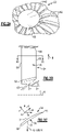
Figure 2A is a perspective view of a portion of a fan section. -
Figure 2B is a schematic cross-sectional view of the fan section. -
Figure 2C is a cross-sectional view a fan blade taken alongline 2C-2C inFigure 2B . -
Figure 3A is a schematic view of fan blade span positions. -
Figure 3B is a schematic view of a cross-section of a fan blade section at a particular span position and its tangential twist and chord parameters. -
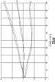
Figure 4A illustrates a relationship between tangential leading edge position, tangential stacking offset position and tangential trailing edge position relative to span position for a set of first example airfoils representing the invention. -
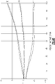
Figure 4B illustrates a relationship between tangential leading edge position, tangential stacking offset position and tangential trailing edge position relative to span position for a set of second example airfoils representing the invention. -
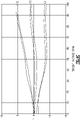
Figure 4C illustrates a relationship between tangential leading edge position, tangential stacking offset position and tangential trailing edge position relative to span position for a set of third example airfoils representing the invention. - Features described in connection with one embodiment are applicable to all embodiments, unless such features are incompatible.
-
Figure 1 schematically illustrates agas turbine engine 20. Thegas turbine engine 20 is disclosed herein as a two-spool turbofan that generally incorporates afan section 22, acompressor section 24, acombustor section 26 and aturbine section 28. Alternative engines might include an augmenter section (not shown) among other systems or features. Thefan section 22 drives air along a bypass flow path B in a bypass duct defined within anacelle 15, while thecompressor section 24 drives air along a core flow path C for compression and communication into thecombustor section 26 then expansion through theturbine section 28. Although depicted as a two-spool turbofan gas turbine engine in the disclosed non-limiting embodiment, it should be understood that the concepts described herein are not limited to use with two-spool turbofans as the teachings may be applied to other types of turbine engines including three-spool architectures. That is, the disclosed airfoils may be used for engine configurations such as, for example, direct fan drives, or two-or three-spool engines with a speed change mechanism coupling the fan with a compressor or a turbine sections. - The
exemplary engine 20 generally includes alow speed spool 30 and ahigh speed spool 32 mounted for rotation about an engine central longitudinal axis X relative to an enginestatic structure 36 viaseveral bearing systems 38. It should be understood thatvarious bearing systems 38 at various locations may alternatively or additionally be provided, and the location ofbearing systems 38 may be varied as appropriate to the application. - The
low speed spool 30 generally includes aninner shaft 40 that interconnects afan 42, a first (or low) pressure compressor 44 and a first (or low)pressure turbine 46. Theinner shaft 40 is connected to thefan 42 through a speed change mechanism, which in exemplarygas turbine engine 20 is illustrated as a gearedarchitecture 48 to drive thefan 42 at a lower speed than thelow speed spool 30. Thehigh speed spool 32 includes anouter shaft 50 that interconnects a second (or high)pressure compressor 52 and a second (or high)pressure turbine 54. Acombustor 56 is arranged inexemplary gas turbine 20 between thehigh pressure compressor 52 and thehigh pressure turbine 54. Amid-turbine frame 57 of the enginestatic structure 36 is arranged generally between thehigh pressure turbine 54 and thelow pressure turbine 46. Themid-turbine frame 57 further supports bearingsystems 38 in theturbine section 28. Theinner shaft 40 and theouter shaft 50 are concentric and rotate viabearing systems 38 about the engine central longitudinal axis X which is collinear with their longitudinal axes. - The core airflow is compressed by the low pressure compressor 44 then the
high pressure compressor 52, mixed and burned with fuel in thecombustor 56, then expanded over thehigh pressure turbine 54 andlow pressure turbine 46. Themid-turbine frame 57 includesairfoils 59 which are in the core airflow path C. Theturbines low speed spool 30 andhigh speed spool 32 in response to the expansion. It will be appreciated that each of the positions of thefan section 22,compressor section 24,combustor section 26,turbine section 28, and fandrive gear system 48 may be varied. For example,gear system 48 may be located aft ofcombustor section 26 or even aft ofturbine section 28, andfan section 22 may be positioned forward or aft of the location ofgear system 48. - The
engine 20 in one example is a high-bypass geared aircraft engine. In a further example, theengine 20 bypass ratio is greater than about six (6), with an example embodiment being greater than about ten (10), the gearedarchitecture 48 is an epicyclic gear train, such as a planetary gear system or other gear system, with a gear reduction ratio of greater than about 2.3 and thelow pressure turbine 46 has a pressure ratio that is greater than about five. In one disclosed embodiment, theengine 20 bypass ratio is greater than about ten (10:1), the fan diameter is significantly larger than that of the low pressure compressor 44, and thelow pressure turbine 46 has a pressure ratio that is greater than about five (5:1).Low pressure turbine 46 pressure ratio is pressure measured prior to inlet oflow pressure turbine 46 as related to the pressure at the outlet of thelow pressure turbine 46 prior to an exhaust nozzle. The gearedarchitecture 48 may be an epicyclic gear train, such as a planetary gear system or other gear system, with a gear reduction ratio of greater than about 2.3:1. It should be understood, however, that the above parameters are only exemplary of one embodiment of a geared architecture engine and that the present invention is applicable to other gas turbine engines including direct drive turbofans. - The example gas turbine engine includes the
fan 42 that comprises in one non-limiting embodiment less than about twenty-six (26) fan blades. In another non-limiting embodiment, thefan section 22 includes less than about twenty (20) fan blades. Moreover, in one disclosed embodiment thelow pressure turbine 46 includes no more than about six (6) turbine rotors schematically indicated at 34. In another non-limiting example embodiment thelow pressure turbine 46 includes about three (3) turbine rotors. A ratio between the number offan blades 42 and the number of low pressure turbine rotors is between about 3.3 and about 8.6. The examplelow pressure turbine 46 provides the driving power to rotate thefan section 22 and therefore the relationship between the number of turbine rotors 34 in thelow pressure turbine 46 and the number ofblades 42 in thefan section 22 disclose an examplegas turbine engine 20 with increased power transfer efficiency. - A significant amount of thrust is provided by the bypass flow B due to the high bypass ratio. The
fan section 22 of theengine 20 is designed for a particular flight condition -- typically cruise at about 0.8 Mach and about 35,000 feet (10,668 metres). The flight condition of 0.8 Mach and 35,000 ft (10,668 m), with the engine at its best fuel consumption - also known as "bucket cruise Thrust Specific Fuel Consumption ('TSFC')" - is the industry standard parameter of lbm of fuel being burned divided by lbf of thrust the engine produces at that minimum point. "Low fan pressure ratio" is the pressure ratio across the fan blade alone, without a Fan Exit Guide Vane ("FEGV") system. The low fan pressure ratio as disclosed herein according to one non-limiting embodiment is less than about 1.55. In another non-limiting embodiment the low fan pressure ratio is less than about 1.45. In another non-limiting embodiment the low fan pressure ratio is from 1.1 to 1.45. "Low corrected fan tip speed" is the actual fan tip speed in ft/sec divided by an industry standard temperature correction of [(Tram °R) / (518.7 °R)]0.5(where °R = K x 9/5). The "Low corrected fan tip speed" as disclosed herein according to one non-limiting embodiment is less than about 1200 ft / second (365.8 m/s). - Referring to
Figure 2A-2C , thefan blade 42 is supported by afan hub 60 that is rotatable about the axis X. Eachfan blade 42 includes anairfoil 64 extending in a radial span direction R from aroot 62 to atip 66. A 0% span position corresponds to a section of theairfoil 64 at the inner flow path (e.g., a platform), and a 100% span position corresponds to a section of theairfoil 64 at thetip 66. - The
root 62 is received in a correspondingly shaped slot in thefan hub 60. Theairfoil 64 extends radially outward of the platform, which provides the inner flow path. The platform may be integral with the fan blade or separately secured to the fan hub, for example. Aspinner 66 is supported relative to thefan hub 60 to provide an aerodynamic inner flow path into thefan section 22. - The
airfoil 64 has anexterior surface 76 providing a contour that extends from a leadingedge 68 aftward in a chord-wise direction H to a trailingedge 70, as shown inFigure 2C . Pressure andsuction sides edges fan blades 42 are positioned about the axis X in a circumferential or tangential direction Y. Any suitable number of fan blades may be used in a given application. - The
exterior surface 76 of theairfoil 64 generates lift based upon its geometry and directs flow along the core flow path C. Thefan blade 42 may be constructed from a composite material, or an aluminum alloy or titanium alloy, or a combination of one or more of these. Abrasion-resistant coatings or other protective coatings may be applied to thefan blade 42. - One characteristic of fan blade performance relates to the fan blade's tangential stacking offset and leading and trailing edge positions (Y direction) relative to a particular span position (R direction). Referring to
Figure 3A , span positions a schematically illustrated from 0% to 100% in 10% increments. Each section at a given span position is provided by a conical cut that corresponds to the shape of the core flow path, as shown by the large dashed lines. In the case of a fan blade with an integral platform, the 0% span position corresponds to the radially innermost location where the airfoil meets the fillet joining the airfoil to the platform. In the case of a fan blade without an integral platform, the 0% span position corresponds to the radially innermost location where the discrete platform meets the exterior surface of the airfoil. In addition to varying with span, tangential projection varies between a hot, running condition and a cold, static ("on the bench") condition. - The YCG corresponds to the location of the center of gravity for a particular section at a given span location relative to a
reference point 80 in the Y direction, as shown inFigure 3B . The center of gravity assumes a homogeneous material. Thereference point 80 is the tangential center of the root, and Yd corresponds to the circumferential distance from thereference point 80 to the center of gravity. - A positive Y value corresponds to the opposite rotational direction as the hub's rotation, or toward the suction side of the airfoil. A negative Y value corresponds to the same rotational direction as the hub's rotation, or toward the pressure side of the airfoil.
- The tangential leading edge location is arranged at the
leading edge 68 for a particular section at a given span location relative to thereference point 80 in the Y direction, as shown inFigure 3B . YLE corresponds to the circumferential distance from thereference point 80 to the tangential leading edge location at a given span location. - The tangential trailing edge location is arranged at the trailing
edge 70 for a particular section at a given span location relative to thereference point 80 in the Y direction. YTE corresponds to the circumferential distance from thereference point 80 to the tangential trailing edge location at a given span location. - The changes in fan blade tangential projection at various span positions can be expressed using the differences YLE-Yd and Yd-YTE, which are tangential distances between the locations. These differences can be used to provide non-dimensional ratios indicative of desired airfoil characteristics.
- In one prior art airfoil, (YLE-Yd)/(Yd-YTE) at 100% span position is about 0.94 and (YLE-Yd)/(Yd-YTE) at 90% span position is about 1; (YLE-Yd)/(Yd-YTE) at 60% span position is about 1.16 and (YLE-Yd)/(Yd-YTE) at 50% span position is about 1.56; and (YLE-Yd)/(Yd-YTE) at 40% span position is about 1.5 and (YLE-Yd)/(Yd-YTE) at 20% span position is about 1.75.
- Example relationships between the tangential projection relative to the span position are shown in
Figures 4A-4C for several example fan blades, each represented by a curve. Only one curve in each graph is discussed for simplicity. The tangential trailing edge curve crosses the tangential stacking offset in the range of 4-10% span position. "About" used in relation to the (YLE-Yd)/(Yd-YTE) ratios means +/- 0.10 in one example, and +/- 0.05 in another example. - Referring to
Figure 4A , (YLE-Yd)/(Yd-YTE) at 100% span position is about 1.1 and (YLE-Yd)/(Yd-YTE) at 90% span position is about 1.3; (YLE-Yd)/(Yd-YTE) at 60% span position is about 1.8 and (YLE-Yd)/(Yd-YTE) at 50% span position is about 0.75; and (YLE-Yd)/(Yd-YTE) at 40% span position is about 1.5 and (YLE-Yd)/(Yd-YTE) at 20% span position is about 2. - Referring to
Figure 4B , (YLE-Yd)/(Yd-YTE) at 100% span position is about 1 and (YLE-Yd)/(Yd-YTE) at 90% span position is about 1.2; (YLE-Yd)/(Yd-YTE) at 60% span position is about 1.3 and (YLE-Yd)/(Yd-YTE) at 50% span position is about 1.4; and (YLE-Yd)/(Yd-YTE) at 40% span position is about 1.5 and (YLE-Yd)/(Yd-YTE) at 20% span position is about 2. - Referring to
Figure 4C , (YLE-Yd)/(Yd-YTE) at 100% span position is about 1.1 and (YLE-Yd)/(Yd-YTE) at 90% span position is about 1; (YLE-Yd)/(Yd-YTE) at 60% span position is about 1.4 and (YLE-Yd)/(Yd-YTE) at 50% span position is about 1.2; and Yd)/(Yd-YTE) at 40% span position is about 1.5 and (YLE-Yd)/(Yd-YTE) at 20% span position is about 2. - The tangential leading and trailing edge positions and tangential stacking offsets in a hot, running condition along the span of the
airfoils 64 relate to the contour of the airfoil and provide necessary fan operation in cruise at the lower, preferential speeds enabled by the gearedarchitecture 48 in order to enhance aerodynamic functionality and thermal efficiency. As used herein, the hot, running condition is the condition during cruise of thegas turbine engine 20. For example, the tangential leading and trailing edge positions and tangential stacking offsets in the hot, running condition can be determined in a known manner using numerical analysis, such as finite element analysis. - It should also be understood that although a particular component arrangement is disclosed in the illustrated embodiment, other arrangements will benefit herefrom.
- Although the different examples have specific components shown in the illustrations, embodiments of this invention are not limited to those particular combinations. It is possible to use some of the components or features from one of the examples in combination with features or components from another one of the examples.
- Although an example embodiment has been disclosed, a worker of ordinary skill in this art would recognize that certain modifications would come within the scope of the claims. For that reason, the following claims should be studied to determine their true scope and content.
Claims (10)
- An airfoil (64) for a turbine engine (20) comprising pressure and suction sides (72, 74) extending in a radial direction from a 0% span position at an inner flow path location to a 100% span position at an airfoil tip (66), wherein the airfoil geometry corresponds to tangential leading and trailing edge curves and a tangential stacking offset curve, wherein the airfoil (64) extends from a root (62), and a zero tangential reference point (80) corresponds to tangential center of the root (62), YLE corresponds to a tangential distance from a leading edge (68) to the reference point (80) at a given span position, YTE corresponds to a tangential distance from a trailing edge (70) to the reference point (80) at a given span position, Yd corresponds to a tangential stacking offset corresponding to a circumferential distance from the reference point (80) to a centre of gravity for a particular section at a given span position, characterised in that (YLE-Yd)/(Yd-YTE) at 40% span position is about 1.5 and (YLE-Yd)/(Yd-YTE) at 20% span position is about 2.
- The airfoil (64) according to claim 1, wherein (YLE-Yd)/(Yd-YTE) at 100% span position is about 1.1 and (YLE-Yd)/(Yd-YTE) at 90% span position is about 1.3.
- The airfoil (64) according to claim 2, wherein (YLE-Yd)/(Yd-YTE) at 60% span position is about 1.8 and (YLE-Yd)/(Yd-YTE) at 50% span position is about 0.75.
- The airfoil (64) according to claim 1, wherein (YLE-Yd)/(Yd-YTE) at 100% span position is about 1 and (YLE-Yd)/(Yd-YTE) at 90% span position is about 1.2.
- The airfoil (64) according to claim 4, wherein (YLE-Yd)/(Yd-YTE) at 60% span position is about 1.3 and (YLE-Yd)/(Yd-YTE) at 50% span position is about 1.4.
- The airfoil (64) according to claim 1, wherein (YLE-Yd)/(Yd-YTE) at 100% span position is about 1.1 and (YLE-Yd)/(Yd-YTE) at 90% span position is about 1.
- The airfoil (64) according to claim 6, wherein (YLE-Yd)/(Yd-YTE) at 60% span position is about 1.4 and (YLE-Yd)/(Yd-YTE) at 50% span position is about 1.2.
- The airfoil (64) according to any preceding claim, wherein the airfoil (64) is a fan blade (42) for a gas turbine engine (20).
- The airfoil (64) according to any preceding claim, wherein (YLE-Yd)/(Yd-YTE) has a tolerance of +/- 0.05.
- A gas turbine engine (20) comprising:a combustor section (26) arranged between a compressor section (24) and a turbine section (28);a fan section (22) having an array of twenty-six or fewer fan blades (42), wherein the fan section (22) has a fan pressure ratio of less than 1.55; anda geared architecture (48) coupling the fan section (22) to the turbine section (28) or the compressor section (24), wherein the fan blades (42) include an airfoil (64) as claimed in any preceding claim.
Applications Claiming Priority (2)
| Application Number | Priority Date | Filing Date | Title |
|---|---|---|---|
| US201461941752P | 2014-02-19 | 2014-02-19 | |
| PCT/US2014/052434 WO2015126452A1 (en) | 2014-02-19 | 2014-08-25 | Gas turbine engine airfoil |
Publications (3)
| Publication Number | Publication Date |
|---|---|
| EP3108101A1 EP3108101A1 (en) | 2016-12-28 |
| EP3108101A4 EP3108101A4 (en) | 2017-03-15 |
| EP3108101B1 true EP3108101B1 (en) | 2022-04-20 |
Family
ID=53878765
Family Applications (1)
| Application Number | Title | Priority Date | Filing Date |
|---|---|---|---|
| EP14883036.7A Active EP3108101B1 (en) | 2014-02-19 | 2014-08-25 | Gas turbine engine airfoil |
Country Status (3)
| Country | Link |
|---|---|
| US (1) | US10385866B2 (en) |
| EP (1) | EP3108101B1 (en) |
| WO (1) | WO2015126452A1 (en) |
Cited By (1)
| Publication number | Priority date | Publication date | Assignee | Title |
|---|---|---|---|---|
| US20230235673A1 (en) * | 2022-01-27 | 2023-07-27 | Raytheon Technologies Corporation | Tangentially bowed airfoil |
Families Citing this family (2)
| Publication number | Priority date | Publication date | Assignee | Title |
|---|---|---|---|---|
| US11248622B2 (en) | 2016-09-02 | 2022-02-15 | Raytheon Technologies Corporation | Repeating airfoil tip strong pressure profile |
| US11187083B2 (en) * | 2019-05-07 | 2021-11-30 | Carrier Corporation | HVAC fan |
Family Cites Families (162)
| Publication number | Priority date | Publication date | Assignee | Title |
|---|---|---|---|---|
| US2746672A (en) | 1950-07-27 | 1956-05-22 | United Aircraft Corp | Compressor blading |
| US2714499A (en) | 1952-10-02 | 1955-08-02 | Gen Electric | Blading for turbomachines |
| US2934259A (en) | 1956-06-18 | 1960-04-26 | United Aircraft Corp | Compressor blading |
| US3287906A (en) | 1965-07-20 | 1966-11-29 | Gen Motors Corp | Cooled gas turbine vanes |
| DE1903642A1 (en) | 1969-01-20 | 1970-08-06 | Bbc Sulzer Turbomaschinen | Blading for rotors of axial compressors |
| GB1350431A (en) | 1971-01-08 | 1974-04-18 | Secr Defence | Gearing |
| US3892358A (en) | 1971-03-17 | 1975-07-01 | Gen Electric | Nozzle seal |
| US3867062A (en) | 1971-09-24 | 1975-02-18 | Theodor H Troller | High energy axial flow transfer stage |
| US3747343A (en) | 1972-02-10 | 1973-07-24 | United Aircraft Corp | Low noise prop-fan |
| US3905191A (en) | 1974-04-10 | 1975-09-16 | Avco Corp | Gas turbine engine with efficient annular bleed manifold |
| US4012172A (en) | 1975-09-10 | 1977-03-15 | Avco Corporation | Low noise blades for axial flow compressors |
| US4130872A (en) | 1975-10-10 | 1978-12-19 | The United States Of America As Represented By The Secretary Of The Air Force | Method and system of controlling a jet engine for avoiding engine surge |
| PL111037B1 (en) | 1975-11-03 | 1980-08-30 | Working blade,especially long one,for steam and gas turbines and axial compressors | |
| GB1516041A (en) | 1977-02-14 | 1978-06-28 | Secr Defence | Multistage axial flow compressor stators |
| GB2041090A (en) | 1979-01-31 | 1980-09-03 | Rolls Royce | By-pass gas turbine engines |
| US4431376A (en) | 1980-10-27 | 1984-02-14 | United Technologies Corporation | Airfoil shape for arrays of airfoils |
| US4605452A (en) | 1981-12-14 | 1986-08-12 | United Technologies Corporation | Single crystal articles having controlled secondary crystallographic orientation |
| US4682935A (en) | 1983-12-12 | 1987-07-28 | General Electric Company | Bowed turbine blade |
| CA1270802A (en) | 1985-02-07 | 1990-06-26 | Edward A. Rothman | Prop-fan with improved stability |
| US4741667A (en) | 1986-05-28 | 1988-05-03 | United Technologies Corporation | Stator vane |
| US4826400A (en) | 1986-12-29 | 1989-05-02 | General Electric Company | Curvilinear turbine airfoil |
| US4900230A (en) | 1989-04-27 | 1990-02-13 | Westinghouse Electric Corp. | Low pressure end blade for a low pressure steam turbine |
| US5088892A (en) | 1990-02-07 | 1992-02-18 | United Technologies Corporation | Bowed airfoil for the compression section of a rotary machine |
| US5211703A (en) | 1990-10-24 | 1993-05-18 | Westinghouse Electric Corp. | Stationary blade design for L-OC row |
| US5221181A (en) | 1990-10-24 | 1993-06-22 | Westinghouse Electric Corp. | Stationary turbine blade having diaphragm construction |
| US5192190A (en) | 1990-12-06 | 1993-03-09 | Westinghouse Electric Corp. | Envelope forged stationary blade for L-2C row |
| US5141400A (en) | 1991-01-25 | 1992-08-25 | General Electric Company | Wide chord fan blade |
| US5167489A (en) | 1991-04-15 | 1992-12-01 | General Electric Company | Forward swept rotor blade |
| US5277549A (en) | 1992-03-16 | 1994-01-11 | Westinghouse Electric Corp. | Controlled reaction L-2R steam turbine blade |
| US5447411A (en) | 1993-06-10 | 1995-09-05 | Martin Marietta Corporation | Light weight fan blade containment system |
| US5524847A (en) | 1993-09-07 | 1996-06-11 | United Technologies Corporation | Nacelle and mounting arrangement for an aircraft engine |
| DE4344189C1 (en) | 1993-12-23 | 1995-08-03 | Mtu Muenchen Gmbh | Axial vane grille with swept front edges |
| US5443367A (en) | 1994-02-22 | 1995-08-22 | United Technologies Corporation | Hollow fan blade dovetail |
| US5433674A (en) | 1994-04-12 | 1995-07-18 | United Technologies Corporation | Coupling system for a planetary gear train |
| US5524341A (en) | 1994-09-26 | 1996-06-11 | Westinghouse Electric Corporation | Method of making a row of mix-tuned turbomachine blades |
| GB2293631B (en) | 1994-09-30 | 1998-09-09 | Gen Electric | Composite fan blade trailing edge reinforcement |
| US5778659A (en) | 1994-10-20 | 1998-07-14 | United Technologies Corporation | Variable area fan exhaust nozzle having mechanically separate sleeve and thrust reverser actuation systems |
| US5525038A (en) | 1994-11-04 | 1996-06-11 | United Technologies Corporation | Rotor airfoils to control tip leakage flows |
| US5624234A (en) | 1994-11-18 | 1997-04-29 | Itt Automotive Electrical Systems, Inc. | Fan blade with curved planform and high-lift airfoil having bulbous leading edge |
| JP3528285B2 (en) | 1994-12-14 | 2004-05-17 | 株式会社日立製作所 | Axial blower |
| US5915917A (en) | 1994-12-14 | 1999-06-29 | United Technologies Corporation | Compressor stall and surge control using airflow asymmetry measurement |
| US6375419B1 (en) | 1995-06-02 | 2002-04-23 | United Technologies Corporation | Flow directing element for a turbine engine |
| US5642985A (en) | 1995-11-17 | 1997-07-01 | United Technologies Corporation | Swept turbomachinery blade |
| GB9607316D0 (en) | 1996-04-09 | 1996-06-12 | Rolls Royce Plc | Swept fan blade |
| US6071077A (en) * | 1996-04-09 | 2000-06-06 | Rolls-Royce Plc | Swept fan blade |
| US5857836A (en) | 1996-09-10 | 1999-01-12 | Aerodyne Research, Inc. | Evaporatively cooled rotor for a gas turbine engine |
| JPH10103002A (en) | 1996-09-30 | 1998-04-21 | Toshiba Corp | Blade for axial flow fluid machine |
| US5725354A (en) | 1996-11-22 | 1998-03-10 | General Electric Company | Forward swept fan blade |
| US5975841A (en) | 1997-10-03 | 1999-11-02 | Thermal Corp. | Heat pipe cooling for turbine stators |
| US6059532A (en) | 1997-10-24 | 2000-05-09 | Alliedsignal Inc. | Axial flow turbo-machine fan blade having shifted tip center of gravity axis |
| US6565334B1 (en) | 1998-07-20 | 2003-05-20 | Phillip James Bradbury | Axial flow fan having counter-rotating dual impeller blade arrangement |
| US6195983B1 (en) | 1999-02-12 | 2001-03-06 | General Electric Company | Leaned and swept fan outlet guide vanes |
| US6290465B1 (en) | 1999-07-30 | 2001-09-18 | General Electric Company | Rotor blade |
| US6312219B1 (en) | 1999-11-05 | 2001-11-06 | General Electric Company | Narrow waist vane |
| US6299412B1 (en) | 1999-12-06 | 2001-10-09 | General Electric Company | Bowed compressor airfoil |
| US6331100B1 (en) | 1999-12-06 | 2001-12-18 | General Electric Company | Doubled bowed compressor airfoil |
| US6341942B1 (en) | 1999-12-18 | 2002-01-29 | General Electric Company | Rotator member and method |
| US6328533B1 (en) | 1999-12-21 | 2001-12-11 | General Electric Company | Swept barrel airfoil |
| US6223616B1 (en) | 1999-12-22 | 2001-05-01 | United Technologies Corporation | Star gear system with lubrication circuit and lubrication method therefor |
| US6318070B1 (en) | 2000-03-03 | 2001-11-20 | United Technologies Corporation | Variable area nozzle for gas turbine engines driven by shape memory alloy actuators |
| US6508630B2 (en) | 2001-03-30 | 2003-01-21 | General Electric Company | Twisted stator vane |
| US6709239B2 (en) | 2001-06-27 | 2004-03-23 | Bharat Heavy Electricals Ltd. | Three dimensional blade |
| US6732502B2 (en) | 2002-03-01 | 2004-05-11 | General Electric Company | Counter rotating aircraft gas turbine engine with high overall pressure ratio compressor |
| US6755612B2 (en) | 2002-09-03 | 2004-06-29 | Rolls-Royce Plc | Guide vane for a gas turbine engine |
| US6814541B2 (en) | 2002-10-07 | 2004-11-09 | General Electric Company | Jet aircraft fan case containment design |
| US7021042B2 (en) | 2002-12-13 | 2006-04-04 | United Technologies Corporation | Geartrain coupling for a turbofan engine |
| FR2853022B1 (en) | 2003-03-27 | 2006-07-28 | Snecma Moteurs | DOUBLE CURVED RECTIFIER DRAW |
| US6899526B2 (en) | 2003-08-05 | 2005-05-31 | General Electric Company | Counterstagger compressor airfoil |
| EP1508669B1 (en) | 2003-08-19 | 2007-03-21 | Siemens Aktiengesellschaft | Stator vanes ring for a compressor and a turbine |
| GB2407136B (en) | 2003-10-15 | 2007-10-03 | Alstom | Turbine rotor blade for gas turbine engine |
| US6994524B2 (en) | 2004-01-26 | 2006-02-07 | United Technologies Corporation | Hollow fan blade for gas turbine engine |
| US7396205B2 (en) | 2004-01-31 | 2008-07-08 | United Technologies Corporation | Rotor blade for a rotary machine |
| EP1582695A1 (en) | 2004-03-26 | 2005-10-05 | Siemens Aktiengesellschaft | Turbomachine blade |
| US7204676B2 (en) | 2004-05-14 | 2007-04-17 | Pratt & Whitney Canada Corp. | Fan blade curvature distribution for high core pressure ratio fan |
| US7114911B2 (en) | 2004-08-25 | 2006-10-03 | General Electric Company | Variable camber and stagger airfoil and method |
| US7547186B2 (en) | 2004-09-28 | 2009-06-16 | Honeywell International Inc. | Nonlinearly stacked low noise turbofan stator |
| DE102004054752A1 (en) | 2004-11-12 | 2006-05-18 | Rolls-Royce Deutschland Ltd & Co Kg | Blade of a flow machine with extended edge profile depth |
| US8087885B2 (en) | 2004-12-01 | 2012-01-03 | United Technologies Corporation | Stacked annular components for turbine engines |
| US7374403B2 (en) | 2005-04-07 | 2008-05-20 | General Electric Company | Low solidity turbofan |
| US7476086B2 (en) | 2005-04-07 | 2009-01-13 | General Electric Company | Tip cambered swept blade |
| US7497664B2 (en) | 2005-08-16 | 2009-03-03 | General Electric Company | Methods and apparatus for reducing vibrations induced to airfoils |
| US8772398B2 (en) | 2005-09-28 | 2014-07-08 | Entrotech Composites, Llc | Linerless prepregs, composite articles therefrom, and related methods |
| US7686567B2 (en) | 2005-12-16 | 2010-03-30 | United Technologies Corporation | Airfoil embodying mixed loading conventions |
| CA2633334C (en) * | 2005-12-29 | 2014-11-25 | Rolls-Royce Power Engineering Plc | Airfoil for a first stage nozzle guide vane |
| US20070160478A1 (en) | 2005-12-29 | 2007-07-12 | Minebea Co., Ltd. | Fan blade with non-varying stagger and camber angels |
| ITMI20060340A1 (en) | 2006-02-27 | 2007-08-28 | Nuovo Pignone Spa | SHOVEL OF A ROTOR OF A SECOND STAGE OF A COMPRESSOR |
| WO2007098595A1 (en) | 2006-03-01 | 2007-09-07 | Magna Powertrain Inc. | Reduced rotor assembly diameter vane pump |
| US7591754B2 (en) | 2006-03-22 | 2009-09-22 | United Technologies Corporation | Epicyclic gear train integral sun gear coupling design |
| DE112007000717A5 (en) | 2006-03-31 | 2009-02-19 | Alstom Technology Ltd. | Guide vane for a turbomachine, in particular for a steam turbine |
| FR2900194A1 (en) | 2006-04-20 | 2007-10-26 | Snecma Sa | AERODYNAMIC PROFILE FOR A TURBINE BLADE |
| JP4863162B2 (en) | 2006-05-26 | 2012-01-25 | 株式会社Ihi | Fan blade of turbofan engine |
| JP4911344B2 (en) | 2006-07-04 | 2012-04-04 | 株式会社Ihi | Turbofan engine |
| US7926260B2 (en) | 2006-07-05 | 2011-04-19 | United Technologies Corporation | Flexible shaft for gas turbine engine |
| GB0620769D0 (en) | 2006-10-19 | 2006-11-29 | Rolls Royce Plc | A fan blade |
| US7497663B2 (en) | 2006-10-26 | 2009-03-03 | General Electric Company | Rotor blade profile optimization |
| FR2908152B1 (en) | 2006-11-08 | 2009-02-06 | Snecma Sa | TURBOMACHINE TURBINE BOW |
| DE102006055869A1 (en) | 2006-11-23 | 2008-05-29 | Rolls-Royce Deutschland Ltd & Co Kg | Rotor and guide blades designing method for turbo-machine i.e. gas turbine engine, involves running skeleton curve in profile section in sectional line angle distribution area lying between upper and lower limit curves |
| US7882693B2 (en) | 2006-11-29 | 2011-02-08 | General Electric Company | Turbofan engine assembly and method of assembling same |
| US7967571B2 (en) | 2006-11-30 | 2011-06-28 | General Electric Company | Advanced booster rotor blade |
| US8292574B2 (en) | 2006-11-30 | 2012-10-23 | General Electric Company | Advanced booster system |
| US8087884B2 (en) | 2006-11-30 | 2012-01-03 | General Electric Company | Advanced booster stator vane |
| US7758306B2 (en) | 2006-12-22 | 2010-07-20 | General Electric Company | Turbine assembly for a gas turbine engine and method of manufacturing the same |
| US7806653B2 (en) | 2006-12-22 | 2010-10-05 | General Electric Company | Gas turbine engines including multi-curve stator vanes and methods of assembling the same |
| GB0701866D0 (en) | 2007-01-31 | 2007-03-14 | Rolls Royce Plc | Tone noise reduction in turbomachines |
| WO2008109036A1 (en) | 2007-03-05 | 2008-09-12 | Xcelaero Corporation | High efficiency cooling fan |
| US8017188B2 (en) | 2007-04-17 | 2011-09-13 | General Electric Company | Methods of making articles having toughened and untoughened regions |
| US10151248B2 (en) * | 2007-10-03 | 2018-12-11 | United Technologies Corporation | Dual fan gas turbine engine and gear train |
| US8205432B2 (en) | 2007-10-03 | 2012-06-26 | United Technologies Corporation | Epicyclic gear train for turbo fan engine |
| DE102008055824B4 (en) | 2007-11-09 | 2016-08-11 | Alstom Technology Ltd. | steam turbine |
| ITMI20072441A1 (en) | 2007-12-28 | 2009-06-29 | Ansaldo Energia Spa | LATEST PRESSURE SECTION STATE STADIUM STAGE OF A STEAM TURBINE |
| ITFO20080002A1 (en) | 2008-02-19 | 2008-05-20 | Paolo Pietricola | ROTORIC AND STATHIC POLES WITH SINUSOIDAL LEAN |
| DE102008011645A1 (en) | 2008-02-28 | 2009-09-03 | Rolls-Royce Deutschland Ltd & Co Kg | Turbomachine with rotors with low rotor outlet angles |
| US8061996B2 (en) | 2008-05-30 | 2011-11-22 | General Electric Company | Wind turbine blade planforms with twisted and tapered tips |
| EP2133573B1 (en) | 2008-06-13 | 2011-08-17 | Siemens Aktiengesellschaft | Vane or blade for an axial flow compressor |
| US8147207B2 (en) * | 2008-09-04 | 2012-04-03 | Siemens Energy, Inc. | Compressor blade having a ratio of leading edge sweep to leading edge dihedral in a range of 1:1 to 3:1 along the radially outer portion |
| DE102008060847B4 (en) | 2008-12-06 | 2020-03-19 | MTU Aero Engines AG | Fluid machine |
| US8167567B2 (en) | 2008-12-17 | 2012-05-01 | United Technologies Corporation | Gas turbine engine airfoil |
| JP4923073B2 (en) | 2009-02-25 | 2012-04-25 | 株式会社日立製作所 | Transonic wing |
| US8105037B2 (en) | 2009-04-06 | 2012-01-31 | United Technologies Corporation | Endwall with leading-edge hump |
| US8172716B2 (en) | 2009-06-25 | 2012-05-08 | United Technologies Corporation | Epicyclic gear system with superfinished journal bearing |
| US8573945B2 (en) | 2009-11-13 | 2013-11-05 | Alstom Technology Ltd. | Compressor stator vane |
| US8360731B2 (en) | 2009-12-04 | 2013-01-29 | United Technologies Corporation | Tip vortex control |
| US9291059B2 (en) | 2009-12-23 | 2016-03-22 | Alstom Technology Ltd. | Airfoil for a compressor blade |
| GB201003084D0 (en) | 2010-02-24 | 2010-04-14 | Rolls Royce Plc | An aerofoil |
| US10294795B2 (en) | 2010-04-28 | 2019-05-21 | United Technologies Corporation | High pitch-to-chord turbine airfoils |
| US8708660B2 (en) | 2010-05-21 | 2014-04-29 | Alstom Technology Ltd | Airfoil for a compressor blade |
| US8747072B2 (en) | 2010-05-21 | 2014-06-10 | Alstom Technology Ltd. | Airfoil for a compressor blade |
| GB2483059A (en) | 2010-08-23 | 2012-02-29 | Rolls Royce Plc | An aerofoil blade with a set-back portion |
| US8393870B2 (en) | 2010-09-08 | 2013-03-12 | United Technologies Corporation | Turbine blade airfoil |
| US8602740B2 (en) | 2010-09-08 | 2013-12-10 | United Technologies Corporation | Turbine vane airfoil |
| US9279329B2 (en) | 2010-10-18 | 2016-03-08 | Mitsubishi Hitachi Power Systems, Ltd. | Transonic blade |
| FR2969230B1 (en) | 2010-12-15 | 2014-11-21 | Snecma | COMPRESSOR BLADE WITH IMPROVED STACKING LAW |
| FR2969120B1 (en) | 2010-12-15 | 2013-08-30 | Eurocopter France | IMPROVED BLADE FOR ANTI-TORQUE HELICOPTER DEVICE |
| FR2971539B1 (en) | 2011-02-10 | 2013-03-08 | Snecma | PLATFORM BLADE ASSEMBLY FOR SUBSONIC FLOW |
| US9074483B2 (en) | 2011-03-25 | 2015-07-07 | General Electric Company | High camber stator vane |
| US8702398B2 (en) | 2011-03-25 | 2014-04-22 | General Electric Company | High camber compressor rotor blade |
| US8684698B2 (en) | 2011-03-25 | 2014-04-01 | General Electric Company | Compressor airfoil with tip dihedral |
| EP2535527A3 (en) | 2011-06-17 | 2014-02-26 | United Technologies Corporation | Turbofan engine comprising a fan rotor support |
| US9790797B2 (en) | 2011-07-05 | 2017-10-17 | United Technologies Corporation | Subsonic swept fan blade |
| US20130022473A1 (en) | 2011-07-22 | 2013-01-24 | Ken Tran | Blades with decreasing exit flow angle |
| US8864457B2 (en) | 2011-10-06 | 2014-10-21 | Siemens Energy, Inc. | Gas turbine with optimized airfoil element angles |
| FR2981118B1 (en) | 2011-10-07 | 2016-01-29 | Snecma | MONOBLOC AUBING DISC WITH AUBES WITH ADAPTED FOOT PROFILE |
| FR2983234B1 (en) | 2011-11-29 | 2014-01-17 | Snecma | AUBE FOR TURBOMACHINE MONOBLOC AUBING DISK |
| US9249666B2 (en) | 2011-12-22 | 2016-02-02 | General Electric Company | Airfoils for wake desensitization and method for fabricating same |
| US9017037B2 (en) | 2012-01-24 | 2015-04-28 | United Technologies Corporation | Rotor with flattened exit pressure profile |
| FR2986285B1 (en) | 2012-01-30 | 2014-02-14 | Snecma | DAWN FOR TURBOREACTOR BLOWER |
| US20130340406A1 (en) * | 2012-01-31 | 2013-12-26 | Edward J. Gallagher | Fan stagger angle for geared gas turbine engine |
| US8402741B1 (en) | 2012-01-31 | 2013-03-26 | United Technologies Corporation | Gas turbine engine shaft bearing configuration |
| US8246292B1 (en) | 2012-01-31 | 2012-08-21 | United Technologies Corporation | Low noise turbine for geared turbofan engine |
| US20130192266A1 (en) | 2012-01-31 | 2013-08-01 | United Technologies Corporation | Geared turbofan gas turbine engine architecture |
| US9140137B2 (en) | 2012-01-31 | 2015-09-22 | United Technologies Corporation | Gas turbine engine mid turbine frame bearing support |
| US20130219922A1 (en) | 2012-02-29 | 2013-08-29 | Jonathan Gilson | Geared gas turbine engine with reduced fan noise |
| US9017036B2 (en) * | 2012-02-29 | 2015-04-28 | United Technologies Corporation | High order shaped curve region for an airfoil |
| US20130219859A1 (en) | 2012-02-29 | 2013-08-29 | Gabriel L. Suciu | Counter rotating low pressure compressor and turbine each having a gear system |
| FR2989107B1 (en) | 2012-04-04 | 2017-03-31 | Snecma | TURBOMACHINE ROTOR BLADE |
| JP5946707B2 (en) | 2012-07-06 | 2016-07-06 | 三菱日立パワーシステムズ株式会社 | Axial turbine blade |
| US9228535B2 (en) | 2012-07-24 | 2016-01-05 | United Technologies Corporation | Geared fan with inner counter rotating compressor |
| WO2014066508A2 (en) | 2012-10-23 | 2014-05-01 | General Electric Company | Unducted thrust producing system architecture |
| FR3009588B1 (en) | 2013-08-07 | 2018-01-26 | Safran Aircraft Engines | MOBILE AUB OF TURBOMACHINE |
| EP3108106B1 (en) | 2014-02-19 | 2022-05-04 | Raytheon Technologies Corporation | Gas turbine engine airfoil |
| US10570915B2 (en) | 2014-02-19 | 2020-02-25 | United Technologies Corporation | Gas turbine engine airfoil |
| US10060263B2 (en) | 2014-09-15 | 2018-08-28 | United Technologies Corporation | Incidence-tolerant, high-turning fan exit stator |
-
2014
- 2014-08-25 EP EP14883036.7A patent/EP3108101B1/en active Active
- 2014-08-25 US US15/113,470 patent/US10385866B2/en active Active
- 2014-08-25 WO PCT/US2014/052434 patent/WO2015126452A1/en active Application Filing
Cited By (2)
| Publication number | Priority date | Publication date | Assignee | Title |
|---|---|---|---|---|
| US20230235673A1 (en) * | 2022-01-27 | 2023-07-27 | Raytheon Technologies Corporation | Tangentially bowed airfoil |
| US11713679B1 (en) * | 2022-01-27 | 2023-08-01 | Raytheon Technologies Corporation | Tangentially bowed airfoil |
Also Published As
| Publication number | Publication date |
|---|---|
| US20170023004A1 (en) | 2017-01-26 |
| US10385866B2 (en) | 2019-08-20 |
| EP3108101A4 (en) | 2017-03-15 |
| EP3108101A1 (en) | 2016-12-28 |
| WO2015126452A1 (en) | 2015-08-27 |
Similar Documents
| Publication | Publication Date | Title |
|---|---|---|
| EP3108106B1 (en) | Gas turbine engine airfoil | |
| EP3108118B1 (en) | Gas turbine engine airfoil | |
| EP3108110B1 (en) | Gas turbine engine airfoil | |
| US10184483B2 (en) | Gas turbine engine airfoil | |
| EP3575551B1 (en) | Gas turbine engine airfoil | |
| US10358925B2 (en) | Gas turbine engine airfoil | |
| EP3108101B1 (en) | Gas turbine engine airfoil | |
| EP3108103B1 (en) | Fan blade for a gas turbine engine | |
| EP3108105B1 (en) | Gas turbine engine airfoil |
Legal Events
| Date | Code | Title | Description |
|---|---|---|---|
| PUAI | Public reference made under article 153(3) epc to a published international application that has entered the european phase |
Free format text: ORIGINAL CODE: 0009012 |
|
| STAA | Information on the status of an ep patent application or granted ep patent |
Free format text: STATUS: REQUEST FOR EXAMINATION WAS MADE |
|
| 17P | Request for examination filed |
Effective date: 20160909 |
|
| AK | Designated contracting states |
Kind code of ref document: A1 Designated state(s): AL AT BE BG CH CY CZ DE DK EE ES FI FR GB GR HR HU IE IS IT LI LT LU LV MC MK MT NL NO PL PT RO RS SE SI SK SM TR |
|
| AX | Request for extension of the european patent |
Extension state: BA ME |
|
| RIN1 | Information on inventor provided before grant (corrected) |
Inventor name: FORD, BARRY M. Inventor name: GALLAGHER, EDWARD J. Inventor name: LIU, LING Inventor name: MONZON, BYRON R. Inventor name: LI, LINDA S. Inventor name: WHITLOW, DARRYL |
|
| A4 | Supplementary search report drawn up and despatched |
Effective date: 20170213 |
|
| RIC1 | Information provided on ipc code assigned before grant |
Ipc: F01D 5/14 20060101AFI20170207BHEP Ipc: F02C 7/00 20060101ALI20170207BHEP Ipc: F04D 29/32 20060101ALI20170207BHEP Ipc: F04D 29/38 20060101ALI20170207BHEP |
|
| DAX | Request for extension of the european patent (deleted) | ||
| STAA | Information on the status of an ep patent application or granted ep patent |
Free format text: STATUS: EXAMINATION IS IN PROGRESS |
|
| 17Q | First examination report despatched |
Effective date: 20190305 |
|
| STAA | Information on the status of an ep patent application or granted ep patent |
Free format text: STATUS: EXAMINATION IS IN PROGRESS |
|
| RAP1 | Party data changed (applicant data changed or rights of an application transferred) |
Owner name: RAYTHEON TECHNOLOGIES CORPORATION |
|
| GRAP | Despatch of communication of intention to grant a patent |
Free format text: ORIGINAL CODE: EPIDOSNIGR1 |
|
| STAA | Information on the status of an ep patent application or granted ep patent |
Free format text: STATUS: GRANT OF PATENT IS INTENDED |
|
| INTG | Intention to grant announced |
Effective date: 20211110 |
|
| GRAS | Grant fee paid |
Free format text: ORIGINAL CODE: EPIDOSNIGR3 |
|
| GRAA | (expected) grant |
Free format text: ORIGINAL CODE: 0009210 |
|
| STAA | Information on the status of an ep patent application or granted ep patent |
Free format text: STATUS: THE PATENT HAS BEEN GRANTED |
|
| AK | Designated contracting states |
Kind code of ref document: B1 Designated state(s): AL AT BE BG CH CY CZ DE DK EE ES FI FR GB GR HR HU IE IS IT LI LT LU LV MC MK MT NL NO PL PT RO RS SE SI SK SM TR |
|
| REG | Reference to a national code |
Ref country code: GB Ref legal event code: FG4D |
|
| REG | Reference to a national code |
Ref country code: CH Ref legal event code: EP |
|
| REG | Reference to a national code |
Ref country code: IE Ref legal event code: FG4D |
|
| REG | Reference to a national code |
Ref country code: DE Ref legal event code: R096 Ref document number: 602014083374 Country of ref document: DE |
|
| REG | Reference to a national code |
Ref country code: AT Ref legal event code: REF Ref document number: 1485292 Country of ref document: AT Kind code of ref document: T Effective date: 20220515 |
|
| REG | Reference to a national code |
Ref country code: LT Ref legal event code: MG9D |
|
| REG | Reference to a national code |
Ref country code: NL Ref legal event code: MP Effective date: 20220420 |
|
| REG | Reference to a national code |
Ref country code: AT Ref legal event code: MK05 Ref document number: 1485292 Country of ref document: AT Kind code of ref document: T Effective date: 20220420 |
|
| PG25 | Lapsed in a contracting state [announced via postgrant information from national office to epo] |
Ref country code: NL Free format text: LAPSE BECAUSE OF FAILURE TO SUBMIT A TRANSLATION OF THE DESCRIPTION OR TO PAY THE FEE WITHIN THE PRESCRIBED TIME-LIMIT Effective date: 20220420 |
|
| PG25 | Lapsed in a contracting state [announced via postgrant information from national office to epo] |
Ref country code: SE Free format text: LAPSE BECAUSE OF FAILURE TO SUBMIT A TRANSLATION OF THE DESCRIPTION OR TO PAY THE FEE WITHIN THE PRESCRIBED TIME-LIMIT Effective date: 20220420 Ref country code: PT Free format text: LAPSE BECAUSE OF FAILURE TO SUBMIT A TRANSLATION OF THE DESCRIPTION OR TO PAY THE FEE WITHIN THE PRESCRIBED TIME-LIMIT Effective date: 20220822 Ref country code: NO Free format text: LAPSE BECAUSE OF FAILURE TO SUBMIT A TRANSLATION OF THE DESCRIPTION OR TO PAY THE FEE WITHIN THE PRESCRIBED TIME-LIMIT Effective date: 20220720 Ref country code: LT Free format text: LAPSE BECAUSE OF FAILURE TO SUBMIT A TRANSLATION OF THE DESCRIPTION OR TO PAY THE FEE WITHIN THE PRESCRIBED TIME-LIMIT Effective date: 20220420 Ref country code: HR Free format text: LAPSE BECAUSE OF FAILURE TO SUBMIT A TRANSLATION OF THE DESCRIPTION OR TO PAY THE FEE WITHIN THE PRESCRIBED TIME-LIMIT Effective date: 20220420 Ref country code: GR Free format text: LAPSE BECAUSE OF FAILURE TO SUBMIT A TRANSLATION OF THE DESCRIPTION OR TO PAY THE FEE WITHIN THE PRESCRIBED TIME-LIMIT Effective date: 20220721 Ref country code: FI Free format text: LAPSE BECAUSE OF FAILURE TO SUBMIT A TRANSLATION OF THE DESCRIPTION OR TO PAY THE FEE WITHIN THE PRESCRIBED TIME-LIMIT Effective date: 20220420 Ref country code: ES Free format text: LAPSE BECAUSE OF FAILURE TO SUBMIT A TRANSLATION OF THE DESCRIPTION OR TO PAY THE FEE WITHIN THE PRESCRIBED TIME-LIMIT Effective date: 20220420 Ref country code: BG Free format text: LAPSE BECAUSE OF FAILURE TO SUBMIT A TRANSLATION OF THE DESCRIPTION OR TO PAY THE FEE WITHIN THE PRESCRIBED TIME-LIMIT Effective date: 20220720 Ref country code: AT Free format text: LAPSE BECAUSE OF FAILURE TO SUBMIT A TRANSLATION OF THE DESCRIPTION OR TO PAY THE FEE WITHIN THE PRESCRIBED TIME-LIMIT Effective date: 20220420 |
|
| PG25 | Lapsed in a contracting state [announced via postgrant information from national office to epo] |
Ref country code: RS Free format text: LAPSE BECAUSE OF FAILURE TO SUBMIT A TRANSLATION OF THE DESCRIPTION OR TO PAY THE FEE WITHIN THE PRESCRIBED TIME-LIMIT Effective date: 20220420 Ref country code: PL Free format text: LAPSE BECAUSE OF FAILURE TO SUBMIT A TRANSLATION OF THE DESCRIPTION OR TO PAY THE FEE WITHIN THE PRESCRIBED TIME-LIMIT Effective date: 20220420 Ref country code: LV Free format text: LAPSE BECAUSE OF FAILURE TO SUBMIT A TRANSLATION OF THE DESCRIPTION OR TO PAY THE FEE WITHIN THE PRESCRIBED TIME-LIMIT Effective date: 20220420 Ref country code: IS Free format text: LAPSE BECAUSE OF FAILURE TO SUBMIT A TRANSLATION OF THE DESCRIPTION OR TO PAY THE FEE WITHIN THE PRESCRIBED TIME-LIMIT Effective date: 20220820 |
|
| REG | Reference to a national code |
Ref country code: DE Ref legal event code: R097 Ref document number: 602014083374 Country of ref document: DE |
|
| PG25 | Lapsed in a contracting state [announced via postgrant information from national office to epo] |
Ref country code: SM Free format text: LAPSE BECAUSE OF FAILURE TO SUBMIT A TRANSLATION OF THE DESCRIPTION OR TO PAY THE FEE WITHIN THE PRESCRIBED TIME-LIMIT Effective date: 20220420 Ref country code: SK Free format text: LAPSE BECAUSE OF FAILURE TO SUBMIT A TRANSLATION OF THE DESCRIPTION OR TO PAY THE FEE WITHIN THE PRESCRIBED TIME-LIMIT Effective date: 20220420 Ref country code: RO Free format text: LAPSE BECAUSE OF FAILURE TO SUBMIT A TRANSLATION OF THE DESCRIPTION OR TO PAY THE FEE WITHIN THE PRESCRIBED TIME-LIMIT Effective date: 20220420 Ref country code: EE Free format text: LAPSE BECAUSE OF FAILURE TO SUBMIT A TRANSLATION OF THE DESCRIPTION OR TO PAY THE FEE WITHIN THE PRESCRIBED TIME-LIMIT Effective date: 20220420 Ref country code: DK Free format text: LAPSE BECAUSE OF FAILURE TO SUBMIT A TRANSLATION OF THE DESCRIPTION OR TO PAY THE FEE WITHIN THE PRESCRIBED TIME-LIMIT Effective date: 20220420 Ref country code: CZ Free format text: LAPSE BECAUSE OF FAILURE TO SUBMIT A TRANSLATION OF THE DESCRIPTION OR TO PAY THE FEE WITHIN THE PRESCRIBED TIME-LIMIT Effective date: 20220420 |
|
| PLBE | No opposition filed within time limit |
Free format text: ORIGINAL CODE: 0009261 |
|
| STAA | Information on the status of an ep patent application or granted ep patent |
Free format text: STATUS: NO OPPOSITION FILED WITHIN TIME LIMIT |
|
| 26N | No opposition filed |
Effective date: 20230123 |
|
| PG25 | Lapsed in a contracting state [announced via postgrant information from national office to epo] |
Ref country code: MC Free format text: LAPSE BECAUSE OF FAILURE TO SUBMIT A TRANSLATION OF THE DESCRIPTION OR TO PAY THE FEE WITHIN THE PRESCRIBED TIME-LIMIT Effective date: 20220420 Ref country code: AL Free format text: LAPSE BECAUSE OF FAILURE TO SUBMIT A TRANSLATION OF THE DESCRIPTION OR TO PAY THE FEE WITHIN THE PRESCRIBED TIME-LIMIT Effective date: 20220420 |
|
| REG | Reference to a national code |
Ref country code: CH Ref legal event code: PL |
|
| PG25 | Lapsed in a contracting state [announced via postgrant information from national office to epo] |
Ref country code: LU Free format text: LAPSE BECAUSE OF NON-PAYMENT OF DUE FEES Effective date: 20220825 Ref country code: LI Free format text: LAPSE BECAUSE OF NON-PAYMENT OF DUE FEES Effective date: 20220831 Ref country code: CH Free format text: LAPSE BECAUSE OF NON-PAYMENT OF DUE FEES Effective date: 20220831 |
|
| REG | Reference to a national code |
Ref country code: BE Ref legal event code: MM Effective date: 20220831 |
|
| PG25 | Lapsed in a contracting state [announced via postgrant information from national office to epo] |
Ref country code: SI Free format text: LAPSE BECAUSE OF FAILURE TO SUBMIT A TRANSLATION OF THE DESCRIPTION OR TO PAY THE FEE WITHIN THE PRESCRIBED TIME-LIMIT Effective date: 20220420 |
|
| P01 | Opt-out of the competence of the unified patent court (upc) registered |
Effective date: 20230520 |
|
| PG25 | Lapsed in a contracting state [announced via postgrant information from national office to epo] |
Ref country code: IE Free format text: LAPSE BECAUSE OF NON-PAYMENT OF DUE FEES Effective date: 20220825 |
|
| PG25 | Lapsed in a contracting state [announced via postgrant information from national office to epo] |
Ref country code: BE Free format text: LAPSE BECAUSE OF NON-PAYMENT OF DUE FEES Effective date: 20220831 |
|
| PG25 | Lapsed in a contracting state [announced via postgrant information from national office to epo] |
Ref country code: IT Free format text: LAPSE BECAUSE OF FAILURE TO SUBMIT A TRANSLATION OF THE DESCRIPTION OR TO PAY THE FEE WITHIN THE PRESCRIBED TIME-LIMIT Effective date: 20220420 |
|
| PG25 | Lapsed in a contracting state [announced via postgrant information from national office to epo] |
Ref country code: HU Free format text: LAPSE BECAUSE OF FAILURE TO SUBMIT A TRANSLATION OF THE DESCRIPTION OR TO PAY THE FEE WITHIN THE PRESCRIBED TIME-LIMIT; INVALID AB INITIO Effective date: 20140825 |
|
| PG25 | Lapsed in a contracting state [announced via postgrant information from national office to epo] |
Ref country code: CY Free format text: LAPSE BECAUSE OF FAILURE TO SUBMIT A TRANSLATION OF THE DESCRIPTION OR TO PAY THE FEE WITHIN THE PRESCRIBED TIME-LIMIT Effective date: 20220420 |
|
| PG25 | Lapsed in a contracting state [announced via postgrant information from national office to epo] |
Ref country code: MK Free format text: LAPSE BECAUSE OF FAILURE TO SUBMIT A TRANSLATION OF THE DESCRIPTION OR TO PAY THE FEE WITHIN THE PRESCRIBED TIME-LIMIT Effective date: 20220420 |
|
| PG25 | Lapsed in a contracting state [announced via postgrant information from national office to epo] |
Ref country code: MT Free format text: LAPSE BECAUSE OF FAILURE TO SUBMIT A TRANSLATION OF THE DESCRIPTION OR TO PAY THE FEE WITHIN THE PRESCRIBED TIME-LIMIT Effective date: 20220420 |
|
| PGFP | Annual fee paid to national office [announced via postgrant information from national office to epo] |
Ref country code: DE Payment date: 20240723 Year of fee payment: 11 |
|
| PGFP | Annual fee paid to national office [announced via postgrant information from national office to epo] |
Ref country code: GB Payment date: 20240723 Year of fee payment: 11 |
|
| PGFP | Annual fee paid to national office [announced via postgrant information from national office to epo] |
Ref country code: FR Payment date: 20240723 Year of fee payment: 11 |