EP3107462B1 - Delivery tool for devices in the pericardial space - Google Patents
Delivery tool for devices in the pericardial space Download PDFInfo
- Publication number
- EP3107462B1 EP3107462B1 EP15749268.7A EP15749268A EP3107462B1 EP 3107462 B1 EP3107462 B1 EP 3107462B1 EP 15749268 A EP15749268 A EP 15749268A EP 3107462 B1 EP3107462 B1 EP 3107462B1
- Authority
- EP
- European Patent Office
- Prior art keywords
- catheter
- delivery tool
- cameras
- camera
- core
- Prior art date
- Legal status (The legal status is an assumption and is not a legal conclusion. Google has not performed a legal analysis and makes no representation as to the accuracy of the status listed.)
- Active
Links
Images





Classifications
-
- A—HUMAN NECESSITIES
- A61—MEDICAL OR VETERINARY SCIENCE; HYGIENE
- A61B—DIAGNOSIS; SURGERY; IDENTIFICATION
- A61B1/00—Instruments for performing medical examinations of the interior of cavities or tubes of the body by visual or photographical inspection, e.g. endoscopes; Illuminating arrangements therefor
- A61B1/04—Instruments for performing medical examinations of the interior of cavities or tubes of the body by visual or photographical inspection, e.g. endoscopes; Illuminating arrangements therefor combined with photographic or television appliances
- A61B1/05—Instruments for performing medical examinations of the interior of cavities or tubes of the body by visual or photographical inspection, e.g. endoscopes; Illuminating arrangements therefor combined with photographic or television appliances characterised by the image sensor, e.g. camera, being in the distal end portion
-
- A—HUMAN NECESSITIES
- A61—MEDICAL OR VETERINARY SCIENCE; HYGIENE
- A61B—DIAGNOSIS; SURGERY; IDENTIFICATION
- A61B1/00—Instruments for performing medical examinations of the interior of cavities or tubes of the body by visual or photographical inspection, e.g. endoscopes; Illuminating arrangements therefor
- A61B1/00147—Holding or positioning arrangements
- A61B1/00154—Holding or positioning arrangements using guiding arrangements for insertion
-
- A—HUMAN NECESSITIES
- A61—MEDICAL OR VETERINARY SCIENCE; HYGIENE
- A61B—DIAGNOSIS; SURGERY; IDENTIFICATION
- A61B1/00—Instruments for performing medical examinations of the interior of cavities or tubes of the body by visual or photographical inspection, e.g. endoscopes; Illuminating arrangements therefor
- A61B1/012—Instruments for performing medical examinations of the interior of cavities or tubes of the body by visual or photographical inspection, e.g. endoscopes; Illuminating arrangements therefor characterised by internal passages or accessories therefor
- A61B1/018—Instruments for performing medical examinations of the interior of cavities or tubes of the body by visual or photographical inspection, e.g. endoscopes; Illuminating arrangements therefor characterised by internal passages or accessories therefor for receiving instruments
-
- A—HUMAN NECESSITIES
- A61—MEDICAL OR VETERINARY SCIENCE; HYGIENE
- A61B—DIAGNOSIS; SURGERY; IDENTIFICATION
- A61B1/00—Instruments for performing medical examinations of the interior of cavities or tubes of the body by visual or photographical inspection, e.g. endoscopes; Illuminating arrangements therefor
- A61B1/313—Instruments for performing medical examinations of the interior of cavities or tubes of the body by visual or photographical inspection, e.g. endoscopes; Illuminating arrangements therefor for introducing through surgical openings, e.g. laparoscopes
- A61B1/3132—Instruments for performing medical examinations of the interior of cavities or tubes of the body by visual or photographical inspection, e.g. endoscopes; Illuminating arrangements therefor for introducing through surgical openings, e.g. laparoscopes for laparoscopy
-
- A—HUMAN NECESSITIES
- A61—MEDICAL OR VETERINARY SCIENCE; HYGIENE
- A61B—DIAGNOSIS; SURGERY; IDENTIFICATION
- A61B5/00—Measuring for diagnostic purposes; Identification of persons
- A61B5/0059—Measuring for diagnostic purposes; Identification of persons using light, e.g. diagnosis by transillumination, diascopy, fluorescence
- A61B5/0082—Measuring for diagnostic purposes; Identification of persons using light, e.g. diagnosis by transillumination, diascopy, fluorescence adapted for particular medical purposes
- A61B5/0084—Measuring for diagnostic purposes; Identification of persons using light, e.g. diagnosis by transillumination, diascopy, fluorescence adapted for particular medical purposes for introduction into the body, e.g. by catheters
-
- A—HUMAN NECESSITIES
- A61—MEDICAL OR VETERINARY SCIENCE; HYGIENE
- A61N—ELECTROTHERAPY; MAGNETOTHERAPY; RADIATION THERAPY; ULTRASOUND THERAPY
- A61N1/00—Electrotherapy; Circuits therefor
- A61N1/02—Details
- A61N1/04—Electrodes
- A61N1/05—Electrodes for implantation or insertion into the body, e.g. heart electrode
- A61N1/0587—Epicardial electrode systems; Endocardial electrodes piercing the pericardium
- A61N1/0592—Introducing the lead through the pericardium with a needle
Definitions
- the present disclosure is related to the field of cardiac rhythm therapy, and a device capable of delivering medical devices for cardiac pacing to the pericardial space under direct visualization and control via percutaneous approach.
- Cardiac pacing is utilized to stimulate the heart, and currently can be performed via two distinct approaches: transvenously to access the endocardium and direct surgical access to the epicardial surfaces.
- Cardiac pacemaker implantation in small children and patients with congenital heart defects presents unique challenges to the cardiologist and surgeon. These patients are often too small for insertion of pacemaker leads through a standard transvenous approach. Congenital anomalies of the heart or venous system may also prevent transvenous lead placement.
- transvenous pacing In addition to small body habitus and limited venous capacitance, other contraindications to transvenous pacing include intracardiac shunts, venous obstruction, and complex venous anatomy with inability to access the right heart endocardium, mechanical tricuspid valve, as well as endocarditis. Patients with congenital heart disease and device-dependent primary electrical diagnoses are likely to require multiple invasive procedures over the course of a lifetime, with attendant cumulative risk of venous occlusion.
- Cardiac resynchronization therapy (CRT) for left ventricular failure and dyssynchrony can be performed via transvenous approach in adults and older children with structurally normal hearts, but may necessitate utilization of a sternotomy or thoracotomy for epicardial placement in smaller patients and/or those with particular forms of congenital heart disease.
- CRT Cardiac resynchronization therapy
- epicardial pacing Although many teenage patients are well served by transvenous pacemakers, epicardial pacing currently remains the conventional technique for infants and those with complex congenital heart disease. Epicardial pacing currently requires either a median sternotomy or thoracotomy to access the epicardial surfaces. The post-operative recovery typically entails multiple days in the intensive care unit with the commensurate costs and risks. Patients undergoing sternotomy are also at increased risk of intrathoracic adhesions with heightened subsequent operative risk of reentry injury should the need for reoperation/exploration arise. Re-operation can be difficult, as the fibrotic tissue must be fully dissected in order to reach viable cardiac tissue for acceptable pacing thresholds.
- transvenous approach Most of the approved technology used to implant devices for managing cardiac rhythm disease, are delivered by a transvenous approach that relies on patient vasculature for navigation under intermediate exposure to fluoroscopy.
- a transvenous approach is not suitable due to restriction in anatomy used for navigation.
- patients are subjected to either thoracotomy or equivalent procedure to expose the heart, allowing direct access to the pericardium.
- U.S. Patent No. 4,991,578 entitled “Method and System for Implanting Self-anchoring epicardial Defibrillation Electrode” introduces a catheter based delivery tool capable of penetrating the pericardium via percutaneous approach, along with a defibrillation lead that can be selectively anchored in the pericardial space.
- U.S. Patent No. 4,270,549 entitled “Method for Implanting Cardiac Electrodes” introduces a delivery tool and method to create a planar tunnel originating from the upper abdomen and terminating at the heart by use of a mandrel attached to a patch electrode, which is secured to the external surface of the heart.
- U.S. Patent Application No. 10/174,454 entitled “Releasable Guide and Method for Cardiac Lead Placement” proposes a similar endoscopic delivery tool capable of direct visualization of the pericardium, equipped with a working channel capable of delivering pericardial injections and leads. A subxiphoid delivery to minimize patient trauma is also detailed.
- US 7 398 781 B1 concerns a method for subxiphoid endoscopic access.
- US 2006/0184048 A1 concerns a tissue visualization and manipulation system.
- US 2008/0183080 A1 relates to an image guided catheter having deployable balloons and a pericardial access procedure.
- US 2005/0271631 A1 relates to material compositions as well as related systems and methods for treating cardiac conditions.
- US 2012/0232339 A1 concerns a surgical device and accessories.
- US 2004/0087831 A1 relates to anatomical access tools and methods.
- US 8 075 532 B2 relates to devices, systems, and methods for pericardial access.
- the present disclosure differs from U.S. Patent Nos. 4,991,578 and 4,270,549 , at least, in that navigation and visualization is achieved with the use of a camera embedded in the delivery tool as opposed to intermittent fluoroscopic images gathered throughout the procedure. As a result, pericardial access is achieved under direct visualization of the tissue, reducing the risk of myocardial puncture, and excess radiologic exposure.
- the present disclosure differs from the proposed technology in U.S. Patent Application No. 10/174,454 , at least, in three ways.
- the delivery tool only offers visualization parallel to the working channel, reducing the capability of a surgeon to accurately gauge depth during pericardial puncture.
- the delivery tool does not offer control of epicardial leads once inside in the pericardial space, limiting implantation to the ventricular surface.
- two cannula are necessary to fixate a lead so only visualization outside of the pericardial space can be achieved.
- the present disclosure differs from U.S. Patent Application Nos. 13/324,781 and 11/549,574 , at least, in that these applications rely on vasculature and fluoroscopy for navigation and visualization of the tool, and do not feature the dexterity at the distal tip necessary for epicardial implantation.
- pericardial pacing or defibrillator lead placement There are currently no approved leads or delivery tools on the market for percutaneous pericardial pacing or defibrillator lead placement. Given the safety and efficacy of available transvenous and epicardial pacing leads, a novel pericardial lead and delivery system would need to demonstrate at least safety, feasibility, and non-inferiority.
- the proposed technology fulfills this unmet need by providing a tool and technique capable of direct, in-line, visualization while positioning medical leads and leadless pacemakers through a percutaneous approach to the pericardial space.
- the technology could also be adapted to improve the delivery of alternative medical devices for procedures such as pericardiocentesis and cardiac ablation from the epicardial surface.
- a novel implantation tool and technique is described to allow minimally-invasive pericardial approach to the epicardial surfaces of the heart under direct in-line visualization.
- a permanent pacing lead or leadless pacemaker can be positioned on the epicardium of the atrium and/or ventricle via a percutaneous access to the pericardium with direct visualization of critical cardiac structures.
- Access is achieved by a subxiphoid approach where a trochar is introduced into the left thorax under direct visualization. The lung is then collapsed through the introduction of carbon dioxide (CO 2 ) insufflation. A camera with a working channel is introduced into the left thorax [pleural cavity?] providing visualization of the surface of the heart. With direct visualization of the camera, graspers, needles, and/or dilators can be used within the working channel to gain access to the pericardial space. After access is achieved, steerable catheters can be positioned within the working channel to selectively navigate and orient medical devices inside the pericardial space.
- CO 2 carbon dioxide
- a single cannula allows the camera to be positioned within the pericardial space itself, providing direct visualization for navigation and anchoring of the medical device.
- a lead can be selectively placed on the right or left atrial epicardium for atrial pacing, or the right and/or left ventricular epicardium for ventricular pacing, cardiac resynchronization therapy, and/or defibrillation. Clear visualization of the pericardium, the beating heart, and critical structures such as coronary arteries is critical to position cardiac devices securely and safely while avoiding cardiac and coronary injury in the pericardial space.
- Subxiphoid pericardial pacing and defibrillator lead delivery would be beneficial to several important groups of patients, who may not be able to receive standard transvenous pacing systems.
- the following is a list of groups that may benefit from this approach; however, the list is not exhaustive.
- a first group may be infants and small children, whose size precludes transvenous pacing and only currently have the option of an open-chest approach to the epicardium. If they require multisite pacing such as for cardiac resynchronization therapy, the open-chest access would need to be even larger or multiple in order to reach the atrium and both ventricles.
- a second group may be patients with congenital heart disease. These patients may have contraindication to transvenous pacing due to intracardiac shunts or may have inaccessible endocardial surfaces due to abnormalities in venous or cardiac anatomy. Therefore, they also would not be amenable to transvenous pacing and would require open-chest access to place epicardial pacing leads. For defibrillation, there is not a suitable FDA-approved alternative, and they often undergo off-label indication use of current leads placed using an open-chest access to the pericardial space.
- a third group may be any patient, regardless of size and anatomy that may benefit from a subxiphoid pericardial approach versus standard epicardial approach due to less invasive procedure reducing surgical morbidity, and potentially shortening recovery time and total expense of procedure.
- a fourth group may be any patient, regardless of size and anatomy, which may benefit from a subxiphoid pericardial approach versus standard transvenous approach as it does not require venous access or fluoroscopy. This is particularly pertinent for those patients requiring left ventricular pacing leads through the coronary sinus system, where x-ray exposure can be substantial.
- a fifth group may be any patient, regardless of size and anatomy, that may benefit from a subxiphoid pericardial approach if it is necessary to patch electrodes to the epicardial or pericardial surfaces of the heart, due to a less invasive technique, shorter recovery time, and total expense of procedure.
- the patient may not have a virgin pericardial sac to be accessed. Previous cardiac surgeries may result in the obliteration of the pericardial space all together.
- a subxiphoid delivery tool may be beneficial to deliver multimodal imaging technology to the pericardial and epicardial surfaces of the heart.
- the multimodal imaging may include direct visualization, ultrasound transducers, multispectral light guide and camera, or any combination thereof. Use of multimodal imaging may help in the detection and identification of anatomical structures for safe and accurate placement of cardiac medical devices such as the coronary artery.
- a subxiphoid approach may also be beneficial for the delivery of biological agents and therapeutic drugs to the pericardial space.
- the delivery of stem cells to the epicardium, pericardium, or pericardial space can be performed with a minimally invasive technique for selective placement under direct visualization.
- Pharmaceuticals can also be delivered directly to the epicardium, pericardium, or pericardial space with a minimally invasive technique for controlled, selective placement under direct visualization.
- procedures that require the access to the coronary arteries such as the placement of stents to remove obstructions will be possible with direct visualization in a subxiphoid approach. This approach will benefit patient groups such as infants and small children that are more susceptible to x-ray and have smaller vasculature, as well as the elderly who cannot tolerate an invasive open approach.
- the invention is defined in claim 1. Preferred embodiments are defined in the dependent claims.
- the present disclosure generally involves an apparatus and methods for delivering medical devices within the pericardial space. While several embodiments are disclosed, it is understood that the present disclosure is exemplary and can be embodied in many different forms. Therefore, the specific features and functionality of the tool disclosed are not to be interpreted as limiting, but to serve a basis for the claims, and to educate one skilled in the art as to the functionality of the tool with respect to the method of device delivery. For the purposes of teaching, the embodiments are direct towards the selective placement and implantation of cardiac leads and leadless pacemakers in the pericardial space, and should not be considered limiting.
- Figure 1 illustrates one embodiment of the proposed delivery tool 100 configured or designed to selectively deliver a cardiac device 101 into the pericardial space and epicardial surface.
- the core 102 of the delivery tool includes of a working channel 103 large enough to accommodate the medical device to be implanted including but not limited to cardiac pacing, defibrillation and resynchronization leads, pacemakers, leadless pacemakers, stem cells, needles, ablation catheters, biopsy punch, or other similar therapeutic devices.
- a second channel 104 includes a camera to provide direct visualization of the distal tip 105 when puncturing and anchoring the pacing lead within the pericardial space.
- the camera channel may contain a rigid camera that may have a fixed or adjustable viewing angle from 0-90°.
- Rotation and/or flexion of an angled or flexible camera may provide a wider field of view and enable a better direct visualization of the surgical site.
- the camera may also contain one or more working channels 111 through which surgical tools can be placed for the procedure.
- the core 102 is surrounded by a rigid shell that is used to hermetically seal the camera within the tool, and provide a rigid body that can be subcutaneously tunneled from a proximal incision to the heart.
- the tool 100 can be placed through a trochar that extends from the subxiphoid incision to the pleural space.
- the tool may be held by handle 106.
- the medical device to be implanted is a pacemaker lead, implantable cardioverter-defibrillator (ICD) lead, pacemaker, leadless pacemaker, stem cells, needle, ablation catheter, biopsy punch or other similar therapeutic device.
- ICD implantable cardioverter-defibrillator
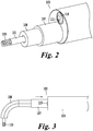
- Figure 2 illustrates a magnified view of the distal tip 105 to highlight a guide sheath 107 and a pre-shaped catheter 108 within the working channel 103 of the delivery tool 100.
- the guide sheath 107 can extend beyond the distal tip 105 and can slide proximal with respect to the pre-shaped catheter 108 to provide an additional two degrees of freedom (DOF), rotating a cardiac pacing lead 109 up to 90° with respect to the camera channel 104 as illustrated in Figure 3 .
- DOF degrees of freedom
- the pre-shaped catheter 108 is composed of a memory shaped alloy.
- the catheter may be one solid piece, or a combination of smaller coaxial segments that are selectively coupled.
- the memory shaped alloy can be pre shaped to any configuration, and may be shaped based on patient anatomy observed with a preoperative scan.
- the memory alloy catheter forms to the working channel 103 of the delivery tool 100.
- the catheter 108 returns to its pre-bent state.
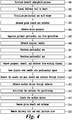
- Figure 4 illustrates a workflow for the method of implanting a medical device using the epicardial delivery tool 100 under percutaneous technique.
- the procedure begins by identifying and making an incision beneath the subxiphoid process (200). Tissue is dissected from the subxiphoid incision to the apex of the heart.
- the delivery tool is passed through a trocar spanning from the subxiphoid incision into the left hemi-thorax, where the apex of the heart and pericardial sac (201) can be observed under direct visualization (202) from a camera 110.
- the guide sheath 107 and pre-shaped catheter 108 are advanced through the working channel 103 of the delivery tool until observed by the camera 110 at the distal tip 105 of the delivery tool (203).
- Micro-graspers 301 are advanced (204) through the pre-shaped catheter 108 until they extend beyond the distal tip 105 of the delivery tool 100.
- the micro-graspers 301 are used to separate (205) the pericardial sac 304 from the epicardial surface 305.
- a surgical needle 302 is advanced (206) through the working channel 103 of the delivery tool 100 until it is observed at the distal tip 105. While still grasping the pericardial sac, the surgeon injects saline through the surgical needle 302 while simultaneously puncturing (207) the pericardial sac 304.
- the micro-graspers 301, the pre-shaped catheter 108 and guide sheath 107 are removed (208) from the working channel 103 of the delivery tool 100.
- a dilator is passed (209) over the surgical needle 302, enlarging the puncture in the pericardial sac 304.
- the guide sheath 107 and pre-shaped catheter 108 are passed though the lumen of the dilator (210) into the pericardial space 307.
- the dilator is removed from the working channel 103 of the delivery tool 100.
- a cardiac pacing lead 109 is advanced through (211) the pre-shaped catheter 108 and into the pericardial space 307.
- the guide sheath 107 slides proximally with respect to the pre-shaped catheter 108, articulating (212) the cardiac lead 109 up to 90°.
- the pacing lead 109 is advanced through the pre-shaped catheter 108 and anchored (213) to the epicardial surface 305 through manual rotation of the cardiac lead 109.
- the pre-shaped catheter 108 and guide sheath 107 are removed (214) from the working channel 103 of the delivery tool 100.
- the epicardial delivery tool 100 is removed from the subxiphoid incision (215).
- the pacing lead 109 is connected to an implanted pacemaker.
- the subxiphoid incision is closed.
- a first working channel 302 facilitates the delivery of the cardiac device 308, while the second working channel 303 is dedicated to guide surgical tools such as micro-graspers 301 to the surgical site. These surgical tools can be used to grab and separate the pericardial sac 304 from the epicardial surface 305, providing a safe region 306 where a puncture can take place as shown in Figure 6 . Electrocautery hooks or ablation tools can also be inserted to selectively burn an opening in the pericardial space 307. After accessing the pericardial space 307, delivery of the cardiac device 308 may be completed as described in Figure 4 .
- the first working channel 303 can also be used to deliver surgical tools to manage the surgical site.
- One such example would be providing an irrigation tube to clear the visual field with saline or suction.
- a second example includes the use of a biopsy punch to sample tissue during a subxiphoid approach.
- the second working channel 303 can also be used to simultaneously deliver a second cardiac device to the pericardial space 307. Deflectable, pre-shaped, and malleable catheters can be used in this working channel to selectively position the surgical tools or cardiac devices.
- the additional working channels may be used to deliver imaging technology to the pericardial space for multimodal diagnostic imaging.
- the imager could be an ultrasound transducer capable of scanning the pericardial surface of the heart. If placed in the pericardial space, the ultrasound transducer may be used to image the epicardial surface of the heart.
- a multispectral light guide or camera may be placed in the working channel to illuminate or image the pericardial sac, pericardial space, or epicardial tissue of the heart.
- At least one additional wavelength may be emitted from the multispectral imaging system. Different illumination wavelengths may increase the visibility of different anatomical structures. Any combination of one or more imaging technologies may be used to detect structures not readily visible under direct visualization such as the coronary artery with an obliterated pericardial space.
- FIG. 7 Another exemplary embodiment of the delivery tool 400 includes detachable surgical tools 401 at the distal end of the delivery tool 400, as illustrated in Figure 7 .
- the surgical tools 401 can be used to selectively target and cut pericardial tissue so that delivery of a device such as the cardiac device 101 can be performed through working channel 402 under direct visualization of camera 403.
- An electrocautery hook 404 is shown in Figure 8 to illustrate how the pericardial sac 405 can be cut 406 and accessed using a detachable surgical tool 401.
- the cutting action is performed by the surgeon manipulating the delivery tool 400 so that the pericardial sac 405 is caught on the surgical hook 404.
- the surgeon can electrify the hook 404 and selectively cut the tissue 407.
- the cardiac device can be delivered to the pericardial space through the working channel 402 as described in Figure 4 .
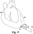
- FIG. 9 illustrates a surgeon using the force sensing needle 501 and micro-graspers 301 to safely puncture the pericardial sac 503.
- One strategy includes using force feedback to indicate a safe region of force that punctures the pericardial sac 503, but does not puncture the epicardial surface 504.
- Force sensing can be achieved by incorporating miniaturized sensors 505 such as a strain gauge, a pressure sensor, or an optical sensor within the needle body, or along the needle length.
- the cardiac device can be implanted using the approach described in Figure 4 .
- FIG. 10 illustrates a steerable catheter 601 placed in the working channel 602 of the delivery tool 600.
- Rotation of an articulation knob 603 provides 0-90° bending of the catheter's distal tip 604, while a second degree of freedom can be implemented by rotating the entire catheter 601.
- the deflectable catheter 601 can be positioned inside the pericardial space 605, and articulated to provide selective placement of the cardiac device 606.
- the additional degrees of freedom allow the cardiac device 606 to be positioned both tangentially 607 and normal 608 to the epicardial surface 609 for proper fixation as shown in Figure 11 .
- the steerable catheter 601 may include a locking knob 610 capable of restricting articulation of the tool to a desired angle.
- the steerable catheter is composed of a memory shaped alloy.
- the catheter may be one solid piece, or a combination of smaller coaxial segments that are selectively coupled.
- the memory shaped alloy can be pre-shaped to any configuration, and may be shaped based on patient anatomy observed with a preoperative scan. When located within the device, the memory-alloy-catheter forms to the working channel of the delivery tool. When extended beyond the working channel of the tool, the catheter conforms to its pre-bent state.
- the delivery tool 700 utilizes a locking member 701 of the catheter 702 to detachably engage a feature 703 on the cardiac device 704.
- the locking member 701 of the catheter 702 can be a cut or groove-sized to catch a raised element (feature 703) of the cardiac device such a tangential pacing barb on a cardiac pacing lead.
- the locking member 701 of the catheter 702 can be a raised feature to selectively engage a groove on the cardiac device 704.
- Both the locking member 701 of the catheter and specialized element (feature 703) comprise a method to selectively couple the catheter 702 to the cardiac device 704. Both features may be used to couple each component at more than one location.
- FIG 14 illustrates another exemplary embodiment of the delivery tool 800 that incorporates a deflectable camera 801 to be used with a rigid working channel 802. After the delivery tool 800 has been tunneled subxiphoid to the surgical site, the deflectable camera 801 can be advanced past the distal tip 803 of the tool 800. Rotation of an articulation knob 804 provides 0-90° bending of the distal tip 803 of the camera 801.
- the additional degree of freedom at the distal tip 803 provides both a tangential and normal view of the heart 804, which can be used to properly visualize the pericardial sac 805 for a safe puncture 806. Additionally, the articulation can be used to visualize anatomy not readily visible behind the heart with the subxiphoid approach such as the great cardiac vein 807.
- the deflectable camera may also contain one or more working channels 812 through which surgical tools can be placed to assist with the procedure.
- Figure 15 illustrates the additional view 808 in which the deflectable camera 801 can provide to selectively fixate the cardiac device under direct visualization.
- the deflectable camera 801 can be extended into the pericardial sac 805 to provide direct visualization of the pericardial space. Visualization of the pericardial space allows the surgeon to identify elements not readily visible with a direct line of sight. Visualization of the pericardial space allows the surgeon to observe fixation of the cardiac device.
- the deflectable camera 801 is passed through a deflectable working channel 809 and exits the side wall of the delivery tool 800 as illustrated in Figure 16 .
- the deflectable camera 801 is housed in a working channel that is formed in the outer surface of the core toward the center of the core.
- the deflectable working channel 809 can be made from a super elastic material such as nitinol, pre-shaped tube, or deflectable catheter.
- the deflectable working channel 809 allows the deflectable camera 801 to be positioned further from the surgical site to provide a wider field of view.
- the deflectable working channel 809 can be selectively bent such that the exit angle of the deflectable camera 801 is between 0-45°.
- Selective flexion of the deflectable working channel 809 is achieved by sliding an outer sheath 810 along the body of the delivery tool 800.
- the outer sheath 810 restrains the deflectable working channel 809 to a view in line with the tool 800.
- the deflectable working channel 809 is allowed to return to its pre-bent shape as illustrated in Figure 16 .
- the outer sheath 810 can be slid along the delivery tool 800 manually, or may be connected to a linear screw mechanism 811. Rotation of a handle connected to the linear screw 811 engages the outer sheath 810 sliding the outer sheath over the delivery tool 800.
- a micro camera 901 may be attached or detachably attached to the cardiac medical device 902 to be implanted.
- Figure 17 illustrates positioning of the micro camera 901 down the lumen of a cardiac pacing lead 902 to provide a coaxial view of the surgical field.
- the cardiac device 902 can be selectively positioned in the pericardial space 903 using either a steerable catheter, or pre-shaped catheter and guide sheath. Direct visualization of the distal tip 904 of the cardiac device 902 is maintained throughout the surgical procedure to ensure the device 902 is secured in the correct anatomy.
- Figure 18 illustrates the two views available to a surgeon when using the camera of the delivery tool 900, as well as the micro camera 901 detachably attached to the cardiac device 902. The two views allow the surgeon to maintain visualization of both the entry of the cardiac device into the pericardial space 905, as well as the distal tip 904 of the cardiac device 902.
- a selectively breakable delivery tool 1000 is presented for the subxiphoid approach.
- the ability to break the delivery tool 1000 in two parts allows the delivery tool 1000 to be miniaturized such that the limiting factor is a feature of the cardiac device to be implanted.
- the delivery tool 1000 breaks into two equal halves. In this instance, the working channel 1001 of the delivery tool 1000 can be minimized to accommodate just the body of the pacing lead.
- the delivery tool 1000 can be separated along part line 1002 by applying a force normal to separation groves 1003 on tool body 1004. Once separated, the delivery tool 1000 can be separated from the cardiac device.
- Figure 19 illustrates the delivery tool 1000 after the delivery tool has been split in half.
- Locking keys 1005 and holes 1006 are used to selectively couple the halves of the tool 1000 together. Proper alignment of the halves may be guaranteed by unique key shape, placement, or any combination thereof.
- the epicardial delivery tool 1100 is designed to accommodate a leadless pacemaker 1101 for fixation in the pericardial space.
- the leadless pacemaker 1101 may be selectively coupled and decoupled from either an unshaped, pre-shaped, or deflectable catheter 1102 that is passed through the working channel 1103 of the delivery tool 1100. Visualization of the surgical field is provided by camera 1104 of the delivery tool 1100.
- the leadless pacemaker 1101 may be press fit into the catheter 1102, and maintain orientation within the tool 1100 via friction between the pacemaker 1101 and the catheter 1102. After gaining access to the pericardial space, the catheter may be manipulated within the working channel 1103 of the delivery tool 1100 to properly position the leadless pacemaker 1101 against the epicardial surface.
- Rotation of the catheter 1102 provides direct torque to the leadless pacemaker 1101, facilitating fixation to the epicardial surface.
- the leadless pacemaker 1101 disengages from the delivery tool 1100.
- the force required to press fit the leadless pacemaker 1101 inside the catheter 1102 is large enough to allow rotation of the catheter 1102 to fixate the device 1101, but small enough to allow the leadless pacemaker 1101 to separate from the catheter 1102 when the catheter is removed from the working channel 1103.
- Figure 20 illustrates a leadless pacemaker 1101 coupled 1104 and selectively decoupled 1105 from the catheter 1102 within working channel 1103 of the delivery tool 1100.
- a locking member 701 of the guide sheath or catheter 702 may detachably engage a feature 1201 on the leadless pacemaker 1202.
- the locking member 701 of the guide sheath 702 can be a cut or groove-sized to catch a raised element (feature 1201) of the leadless pacemaker 1202 such as a tangential pacing barb or fixation hook 1201 as shown in Figure 21 .
- the locking member of the sheath can be a raised feature to selectively engage a groove on the leadless pacemaker 1202.
- Both the locking member 701 and specialized element (feature 1201) comprise a method to selectively couple and decouple the delivery tool 700 to the leadless pacemaker 1202.
- Both features may be used to couple each component at more than one location.
- rotation of the guide sheath handle 705 provides one-to-one rotation 706 of the leadless pacemaker 1202. This rotation may be used to orient or fixate the leadless pacemaker 1202 in the pericardial space.
- the guide sheath may have a secondary feature to ensure that back rotation of the guide sheath 702 does not decouple the leadless pacemaker 1202 from the guide sheath 702.
- the guide sheath 702 may be rotated and orientated in a way as to selectively decouple the locking groove 701 from the raised feature 1201.
- the leadless pacemaker 1301 is free to slide within an unshaped, pre-shaped, or deflectable catheter 1302.
- Manipulation of the catheter 1302 in the working channel 1303 of the delivery tool 1300 allows the leadless pacemaker 1301 to be selectively positioned against the epicardial surface in the pericardial space.
- Figure 22 illustrates the delivery tool 1300 of this design, with accompanying leadless pacemaker 1301 and torque tool 1304 shown in Figure 23 .
- the leadless pacemaker 1301 has pocket 1305 capable selectively engaging or disengaging torque tool 1304. Selective engagement may be provided by magnetism or another force of the like.
- the torque tool 1304 is inserted into pocket 1305 and used to stabilize the leadless pacemaker 1301 within the catheter 1302.
- the leadless pacemaker 1301 may be advanced through the catheter 1302 by manipulation of the torque tool 1304. Rotation of the torque tool 1304 transmits one-to-one force directly to the lead less pacemaker 1301, allowing the surgeon to fixate the pacemaker in the pericardial space. Once the leadless pacemaker 1301 has been fixated, the torque tool 1304 is disengaged from the leadless pacemaker 1301 by removing it from the catheter 1302. The force required to couple the leadless pacemaker 1301 to the torque tool 1304 is large enough to allow rotation of the catheter 1302 to fixate the device 1301, but small enough to allow the leadless pacemaker 1301 to separate from the torque tool 1304 when an axial force is applied.
- a delivery tool 1400 is used to deliver a micro pacemaker 1401 within the epicardial tissue as shown in Figure 24 .
- a needle 1402 is positioned within the working channel 1403 of the delivery tool 1400.
- the needle 1402 has a micro pacemaker 1401 press fit within the lumen.
- Applications for a micro pacemaker may include fetal pacing.
- the needle 1402 is advanced into the pericardial sac. Intraluminal pressure may release the micro pacemaker from the needle 1402, injecting the micro-pacemaker 1401 into the pericardial space.
- the delivery tool 1400 may be used to deliver therapeutic agents to the epicardium, pericardium, or pericardial space under direct visualization.
- the therapeutic agents may be stem cells for regenerative therapy.
- the therapeutic agents may be pharmaceuticals for drug induced therapy.
- the therapeutics may be delivered with the use of a needle 1402 that has been passed through the working channel of the delivery tool 1400.
- a delivery tool 1500 can be used to delivery therapy devices to the coronary arteries 1501.
- the coronary arteries 1501 can be accessed and visualized under direct visualization of the deflectable camera 1502 as shown in Figure 25 .
- a sheath 1503 may be passed through the working channel 1504 of the delivery tool 1500 to the coronary artery 1501.
- a stent 1505 can be placed on a balloon catheter and advanced to the obstruction in the coronary artery 1501.
- the balloon can be inflated, relieving the obstruction in the coronary artery 1501 and a closure device is deployed.
- the coronary artery 1501 can be observed under direct visualization of the camera for any bleeding.
Landscapes
- Health & Medical Sciences (AREA)
- Life Sciences & Earth Sciences (AREA)
- Surgery (AREA)
- Heart & Thoracic Surgery (AREA)
- General Health & Medical Sciences (AREA)
- Veterinary Medicine (AREA)
- Public Health (AREA)
- Animal Behavior & Ethology (AREA)
- Biomedical Technology (AREA)
- Engineering & Computer Science (AREA)
- Nuclear Medicine, Radiotherapy & Molecular Imaging (AREA)
- Radiology & Medical Imaging (AREA)
- Biophysics (AREA)
- Medical Informatics (AREA)
- Molecular Biology (AREA)
- Physics & Mathematics (AREA)
- Pathology (AREA)
- Optics & Photonics (AREA)
- Cardiology (AREA)
- Electrotherapy Devices (AREA)
- Endoscopes (AREA)
Description
- The present disclosure is related to the field of cardiac rhythm therapy, and a device capable of delivering medical devices for cardiac pacing to the pericardial space under direct visualization and control via percutaneous approach.
- Cardiac pacing is utilized to stimulate the heart, and currently can be performed via two distinct approaches: transvenously to access the endocardium and direct surgical access to the epicardial surfaces. Cardiac pacemaker implantation in small children and patients with congenital heart defects presents unique challenges to the cardiologist and surgeon. These patients are often too small for insertion of pacemaker leads through a standard transvenous approach. Congenital anomalies of the heart or venous system may also prevent transvenous lead placement. In addition to small body habitus and limited venous capacitance, other contraindications to transvenous pacing include intracardiac shunts, venous obstruction, and complex venous anatomy with inability to access the right heart endocardium, mechanical tricuspid valve, as well as endocarditis. Patients with congenital heart disease and device-dependent primary electrical diagnoses are likely to require multiple invasive procedures over the course of a lifetime, with attendant cumulative risk of venous occlusion. Cardiac resynchronization therapy (CRT) for left ventricular failure and dyssynchrony can be performed via transvenous approach in adults and older children with structurally normal hearts, but may necessitate utilization of a sternotomy or thoracotomy for epicardial placement in smaller patients and/or those with particular forms of congenital heart disease.
- Although many teenage patients are well served by transvenous pacemakers, epicardial pacing currently remains the conventional technique for infants and those with complex congenital heart disease. Epicardial pacing currently requires either a median sternotomy or thoracotomy to access the epicardial surfaces. The post-operative recovery typically entails multiple days in the intensive care unit with the commensurate costs and risks. Patients undergoing sternotomy are also at increased risk of intrathoracic adhesions with heightened subsequent operative risk of reentry injury should the need for reoperation/exploration arise. Re-operation can be difficult, as the fibrotic tissue must be fully dissected in order to reach viable cardiac tissue for acceptable pacing thresholds.
- Most of the approved technology used to implant devices for managing cardiac rhythm disease, are delivered by a transvenous approach that relies on patient vasculature for navigation under intermediate exposure to fluoroscopy. For pediatric, single ventricle, and abnormal vasculature patients, a transvenous approach is not suitable due to restriction in anatomy used for navigation. As a result, patients are subjected to either thoracotomy or equivalent procedure to expose the heart, allowing direct access to the pericardium.
- There are several existing patents that address exposure of the pericardium for the placement of epicardial devices and that propose the use of a minimally invasive approach to reduce patient trauma.
U.S. Patent No. 4,991,578 entitled "Method and System for Implanting Self-anchoring epicardial Defibrillation Electrode" introduces a catheter based delivery tool capable of penetrating the pericardium via percutaneous approach, along with a defibrillation lead that can be selectively anchored in the pericardial space. -
U.S. Patent No. 4,270,549 entitled "Method for Implanting Cardiac Electrodes" introduces a delivery tool and method to create a planar tunnel originating from the upper abdomen and terminating at the heart by use of a mandrel attached to a patch electrode, which is secured to the external surface of the heart.U.S. Patent Application No. 10/174,454 entitled "Releasable Guide and Method for Cardiac Lead Placement" proposes a similar endoscopic delivery tool capable of direct visualization of the pericardium, equipped with a working channel capable of delivering pericardial injections and leads. A subxiphoid delivery to minimize patient trauma is also detailed. In the future, leadless pacemakers will replace many of the permanent pacing, defibrillation, and cardiac resynchronization leads for both Endocardial and epicardial procedures. These medical devices will require specialized delivery tools to selectively place them throughout the heart for cardiac rhythm therapy.U.S. Patent Application No. 13/324,781 titled "Delivery Catheter Systems and Methods" details a catheter based delivery tool and feature based leadless pacemaker that can be selectively coupled for implantation. Likewise,U.S. Patent Application No. 11/549,574 "Delivery System for Implantable Biostimulator" details a second concept of selectively coupling a leadless pacemaker to a catheter based delivery tool, for implantation in the endocardium. -
US 7 398 781 B1 concerns a method for subxiphoid endoscopic access. -
US 2006/0184048 A1 concerns a tissue visualization and manipulation system. -
US 2008/0183080 A1 relates to an image guided catheter having deployable balloons and a pericardial access procedure. -
US 2005/0271631 A1 relates to material compositions as well as related systems and methods for treating cardiac conditions. -
US 2012/0232339 A1 concerns a surgical device and accessories. -
US 2004/0087831 A1 relates to anatomical access tools and methods. -
US 2006/0149129 A1 describes a catheter with multiple visual elements. -
US 8 075 532 B2 relates to devices, systems, and methods for pericardial access. - The present disclosure differs from
U.S. Patent Nos. 4,991,578 and4,270,549 , at least, in that navigation and visualization is achieved with the use of a camera embedded in the delivery tool as opposed to intermittent fluoroscopic images gathered throughout the procedure. As a result, pericardial access is achieved under direct visualization of the tissue, reducing the risk of myocardial puncture, and excess radiologic exposure. - The present disclosure differs from the proposed technology in
U.S. Patent Application No. 10/174,454 , at least, in three ways. First, the delivery tool only offers visualization parallel to the working channel, reducing the capability of a surgeon to accurately gauge depth during pericardial puncture. Second, the delivery tool does not offer control of epicardial leads once inside in the pericardial space, limiting implantation to the ventricular surface. Third, two cannula are necessary to fixate a lead so only visualization outside of the pericardial space can be achieved. - The present disclosure differs from
U.S. Patent Application Nos. 13/324,781 and11/549,574 - There are currently no approved leads or delivery tools on the market for percutaneous pericardial pacing or defibrillator lead placement. Given the safety and efficacy of available transvenous and epicardial pacing leads, a novel pericardial lead and delivery system would need to demonstrate at least safety, feasibility, and non-inferiority. The proposed technology fulfills this unmet need by providing a tool and technique capable of direct, in-line, visualization while positioning medical leads and leadless pacemakers through a percutaneous approach to the pericardial space. The technology could also be adapted to improve the delivery of alternative medical devices for procedures such as pericardiocentesis and cardiac ablation from the epicardial surface.
- Given the significant limitations of the current approaches for cardiac pacing, defibrillation, and resynchronization, a novel implantation tool and technique is described to allow minimally-invasive pericardial approach to the epicardial surfaces of the heart under direct in-line visualization. Using this tool and technique, a permanent pacing lead or leadless pacemaker can be positioned on the epicardium of the atrium and/or ventricle via a percutaneous access to the pericardium with direct visualization of critical cardiac structures.
- Access is achieved by a subxiphoid approach where a trochar is introduced into the left thorax under direct visualization. The lung is then collapsed through the introduction of carbon dioxide (CO2) insufflation. A camera with a working channel is introduced into the left thorax [pleural cavity?] providing visualization of the surface of the heart. With direct visualization of the camera, graspers, needles, and/or dilators can be used within the working channel to gain access to the pericardial space. After access is achieved, steerable catheters can be positioned within the working channel to selectively navigate and orient medical devices inside the pericardial space.
- A single cannula allows the camera to be positioned within the pericardial space itself, providing direct visualization for navigation and anchoring of the medical device. With this approach, a lead can be selectively placed on the right or left atrial epicardium for atrial pacing, or the right and/or left ventricular epicardium for ventricular pacing, cardiac resynchronization therapy, and/or defibrillation. Clear visualization of the pericardium, the beating heart, and critical structures such as coronary arteries is critical to position cardiac devices securely and safely while avoiding cardiac and coronary injury in the pericardial space.
- Subxiphoid pericardial pacing and defibrillator lead delivery would be beneficial to several important groups of patients, who may not be able to receive standard transvenous pacing systems. The following is a list of groups that may benefit from this approach; however, the list is not exhaustive.
- A first group may be infants and small children, whose size precludes transvenous pacing and only currently have the option of an open-chest approach to the epicardium. If they require multisite pacing such as for cardiac resynchronization therapy, the open-chest access would need to be even larger or multiple in order to reach the atrium and both ventricles.
- A second group may be patients with congenital heart disease. These patients may have contraindication to transvenous pacing due to intracardiac shunts or may have inaccessible endocardial surfaces due to abnormalities in venous or cardiac anatomy. Therefore, they also would not be amenable to transvenous pacing and would require open-chest access to place epicardial pacing leads. For defibrillation, there is not a suitable FDA-approved alternative, and they often undergo off-label indication use of current leads placed using an open-chest access to the pericardial space.
- A third group may be any patient, regardless of size and anatomy that may benefit from a subxiphoid pericardial approach versus standard epicardial approach due to less invasive procedure reducing surgical morbidity, and potentially shortening recovery time and total expense of procedure.
- A fourth group may be any patient, regardless of size and anatomy, which may benefit from a subxiphoid pericardial approach versus standard transvenous approach as it does not require venous access or fluoroscopy. This is particularly pertinent for those patients requiring left ventricular pacing leads through the coronary sinus system, where x-ray exposure can be substantial.
- A fifth group may be any patient, regardless of size and anatomy, that may benefit from a subxiphoid pericardial approach if it is necessary to patch electrodes to the epicardial or pericardial surfaces of the heart, due to a less invasive technique, shorter recovery time, and total expense of procedure.
- In some cases, the patient may not have a virgin pericardial sac to be accessed. Previous cardiac surgeries may result in the obliteration of the pericardial space all together. In this instance, a subxiphoid delivery tool may be beneficial to deliver multimodal imaging technology to the pericardial and epicardial surfaces of the heart. The multimodal imaging may include direct visualization, ultrasound transducers, multispectral light guide and camera, or any combination thereof. Use of multimodal imaging may help in the detection and identification of anatomical structures for safe and accurate placement of cardiac medical devices such as the coronary artery.
- A subxiphoid approach may also be beneficial for the delivery of biological agents and therapeutic drugs to the pericardial space. In one application, the delivery of stem cells to the epicardium, pericardium, or pericardial space can be performed with a minimally invasive technique for selective placement under direct visualization. Pharmaceuticals can also be delivered directly to the epicardium, pericardium, or pericardial space with a minimally invasive technique for controlled, selective placement under direct visualization. In addition, procedures that require the access to the coronary arteries such as the placement of stents to remove obstructions will be possible with direct visualization in a subxiphoid approach. This approach will benefit patient groups such as infants and small children that are more susceptible to x-ray and have smaller vasculature, as well as the elderly who cannot tolerate an invasive open approach. The invention is defined in
claim 1. Preferred embodiments are defined in the dependent claims. - A more complete appreciation of the invention and many of the attendant advantages thereof will be readily obtained as the same becomes better understood by reference to the following detailed description when considered in connection with the accompanying drawings, wherein:
-
Figure 1 illustrates an exemplary embodiment of a delivery tool configured or designed to deliver cardiac pacing leads; -
Figure 2 illustrates a magnified view of a distal tip of the delivery tool to highlight delivery tool features; -
Figure 3 illustrates a top down view of the distal tip illustrating articulation of a pre-shaped catheter; -
Figure 4 illustrates a clinical workflow for using the delivery tool to place a cardiac device; -
Figure 5 illustrates an exemplary embodiment of the delivery tool including multiple working channels for surgical tools; -
Figure 6 illustrates grasping pericardium with micrograspers for safe needle puncture of the pericardial sac; -
Figure 7 illustrates an exemplary embodiment of the delivery tool shown with an electrocautery hook as a detachable surgical tool; -
Figure 8 illustrates cutting a hole in the pericardial sac using an electrocautery hook as a detachable surgical tool on the delivery tool; -
Figure 9 illustrates an exemplary embodiment using a force sensing needle to safely puncture the pericardium; -
Figure 10 illustrates an exemplary embodiment using a deflectable catheter to selectively position a medical device; -
Figure 11 illustrates articulating the deflectable catheter for selective placement of the medical device tangential or normal to the epicardial surface; -
Figure 12 illustrates an exemplary embodiment using a locking feature to engage and rotate a cardiac device for placement and fixation; -
Figure 13 illustrates rotation of a sheath that provides one to one rotation of the medical device at the tip; -
Figure 14 illustrates an exemplary embodiment using a deflectable camera to provide additional viewing angles for the delivery tool; -
Figure 15 illustrates an additional viewing angle provided by the deflectable camera showing the needle moving tangentially to the pericardial sac, instead of normal to the pericardial sac; -
Figure 16 illustrates an exemplary embodiment incorporating a deflectable working channel for the deflectable scope so that a larger surgical field of view can be obtained; -
Figure 17 illustrates an exemplary embodiment incorporating a micro camera within the medical device; -
Figure 18 illustrates two views that can be seen with the delivery tool camera, and the micro camera attached to the cardiac device; -
Figure 19 illustrates an exemplary embodiment of a breakable delivery tool featuring locking keys and grooves; -
Figure 20 illustrates an exemplary embodiment where the cardiac device is a leadless pacemaker that can be selectively coupled and decoupled from the catheter using a press fit; -
Figure 21 illustrates an exemplary embodiment of a leadless pacemaker that includes a raised feature for selective coupling with the delivery tool; -
Figure 22 illustrates an exemplary embodiment of the tool where the leadless pacemaker is free to move within the tool and catheter; -
Figure 23 illustrates a leadless pacemaker and torque tool highlighting the interlocking interface to control positioning and fixation of the pacemaker; -
Figure 24 illustrates an exemplary embodiment where the delivery tool is used to deliver a micro pacemaker for fetal pacing; and -
Figure 25 illustrates an exemplary embodiment where the delivery tool is used to deliver therapy devices such as stents to the coronary arteries under direct visualization of the deflectable camera. - The present disclosure generally involves an apparatus and methods for delivering medical devices within the pericardial space. While several embodiments are disclosed, it is understood that the present disclosure is exemplary and can be embodied in many different forms. Therefore, the specific features and functionality of the tool disclosed are not to be interpreted as limiting, but to serve a basis for the claims, and to educate one skilled in the art as to the functionality of the tool with respect to the method of device delivery. For the purposes of teaching, the embodiments are direct towards the selective placement and implantation of cardiac leads and leadless pacemakers in the pericardial space, and should not be considered limiting.
-
Figure 1 illustrates one embodiment of the proposeddelivery tool 100 configured or designed to selectively deliver acardiac device 101 into the pericardial space and epicardial surface. Thecore 102 of the delivery tool includes of a workingchannel 103 large enough to accommodate the medical device to be implanted including but not limited to cardiac pacing, defibrillation and resynchronization leads, pacemakers, leadless pacemakers, stem cells, needles, ablation catheters, biopsy punch, or other similar therapeutic devices. Asecond channel 104 includes a camera to provide direct visualization of thedistal tip 105 when puncturing and anchoring the pacing lead within the pericardial space. The camera channel may contain a rigid camera that may have a fixed or adjustable viewing angle from 0-90°. Rotation and/or flexion of an angled or flexible camera may provide a wider field of view and enable a better direct visualization of the surgical site. The camera may also contain one or more workingchannels 111 through which surgical tools can be placed for the procedure. Thecore 102 is surrounded by a rigid shell that is used to hermetically seal the camera within the tool, and provide a rigid body that can be subcutaneously tunneled from a proximal incision to the heart. Alternatively, thetool 100 can be placed through a trochar that extends from the subxiphoid incision to the pleural space. The tool may be held byhandle 106. - The medical device to be implanted is a pacemaker lead, implantable cardioverter-defibrillator (ICD) lead, pacemaker, leadless pacemaker, stem cells, needle, ablation catheter, biopsy punch or other similar therapeutic device.
- It is intended that access of the pericardial space and implantation of a medical device be performed through the working
channel 103 of the delivery tool.Figure 2 illustrates a magnified view of thedistal tip 105 to highlight aguide sheath 107 and apre-shaped catheter 108 within the workingchannel 103 of thedelivery tool 100. Theguide sheath 107 can extend beyond thedistal tip 105 and can slide proximal with respect to thepre-shaped catheter 108 to provide an additional two degrees of freedom (DOF), rotating acardiac pacing lead 109 up to 90° with respect to thecamera channel 104 as illustrated inFigure 3 . - In another embodiment of the device, the
pre-shaped catheter 108 is composed of a memory shaped alloy. The catheter may be one solid piece, or a combination of smaller coaxial segments that are selectively coupled. The memory shaped alloy can be pre shaped to any configuration, and may be shaped based on patient anatomy observed with a preoperative scan. When located within the device, the memory alloy catheter forms to the workingchannel 103 of thedelivery tool 100. When extended beyond the workingchannel 103 of thecore 102, thecatheter 108 returns to its pre-bent state. -
Figure 4 illustrates a workflow for the method of implanting a medical device using theepicardial delivery tool 100 under percutaneous technique. The procedure begins by identifying and making an incision beneath the subxiphoid process (200). Tissue is dissected from the subxiphoid incision to the apex of the heart. The delivery tool is passed through a trocar spanning from the subxiphoid incision into the left hemi-thorax, where the apex of the heart and pericardial sac (201) can be observed under direct visualization (202) from acamera 110. Theguide sheath 107 andpre-shaped catheter 108 are advanced through the workingchannel 103 of the delivery tool until observed by thecamera 110 at thedistal tip 105 of the delivery tool (203).Micro-graspers 301 are advanced (204) through thepre-shaped catheter 108 until they extend beyond thedistal tip 105 of thedelivery tool 100. The micro-graspers 301 are used to separate (205) thepericardial sac 304 from theepicardial surface 305. Asurgical needle 302 is advanced (206) through the workingchannel 103 of thedelivery tool 100 until it is observed at thedistal tip 105. While still grasping the pericardial sac, the surgeon injects saline through thesurgical needle 302 while simultaneously puncturing (207) thepericardial sac 304. - Once the
pericardial sac 304 is punctured, themicro-graspers 301, thepre-shaped catheter 108 and guidesheath 107 are removed (208) from the workingchannel 103 of thedelivery tool 100. A dilator is passed (209) over thesurgical needle 302, enlarging the puncture in thepericardial sac 304. Theguide sheath 107 andpre-shaped catheter 108 are passed though the lumen of the dilator (210) into thepericardial space 307. The dilator is removed from the workingchannel 103 of thedelivery tool 100. Acardiac pacing lead 109 is advanced through (211) thepre-shaped catheter 108 and into thepericardial space 307. Theguide sheath 107 slides proximally with respect to thepre-shaped catheter 108, articulating (212) thecardiac lead 109 up to 90°. Thepacing lead 109 is advanced through thepre-shaped catheter 108 and anchored (213) to theepicardial surface 305 through manual rotation of thecardiac lead 109. Thepre-shaped catheter 108 and guidesheath 107 are removed (214) from the workingchannel 103 of thedelivery tool 100. Theepicardial delivery tool 100 is removed from the subxiphoid incision (215). Thepacing lead 109 is connected to an implanted pacemaker. The subxiphoid incision is closed. - In another exemplary embodiment of the
delivery tool 300 illustrated inFigure 5 , there is described multiple working channels which may be used interchangeably to deliver cardiac devices to the epicardial space with a subxiphoid approach. This configuration can provide better control over access to the pericardial space. A first workingchannel 302 facilitates the delivery of thecardiac device 308, while the second workingchannel 303 is dedicated to guide surgical tools such asmicro-graspers 301 to the surgical site. These surgical tools can be used to grab and separate thepericardial sac 304 from theepicardial surface 305, providing asafe region 306 where a puncture can take place as shown inFigure 6 . Electrocautery hooks or ablation tools can also be inserted to selectively burn an opening in thepericardial space 307. After accessing thepericardial space 307, delivery of thecardiac device 308 may be completed as described inFigure 4 . - The
first working channel 303 can also be used to deliver surgical tools to manage the surgical site. One such example would be providing an irrigation tube to clear the visual field with saline or suction. A second example includes the use of a biopsy punch to sample tissue during a subxiphoid approach. Thesecond working channel 303 can also be used to simultaneously deliver a second cardiac device to thepericardial space 307. Deflectable, pre-shaped, and malleable catheters can be used in this working channel to selectively position the surgical tools or cardiac devices. - Alternatively, the additional working channels may be used to deliver imaging technology to the pericardial space for multimodal diagnostic imaging. In one embodiment, the imager could be an ultrasound transducer capable of scanning the pericardial surface of the heart. If placed in the pericardial space, the ultrasound transducer may be used to image the epicardial surface of the heart. Alternatively, a multispectral light guide or camera may be placed in the working channel to illuminate or image the pericardial sac, pericardial space, or epicardial tissue of the heart. At least one additional wavelength may be emitted from the multispectral imaging system. Different illumination wavelengths may increase the visibility of different anatomical structures. Any combination of one or more imaging technologies may be used to detect structures not readily visible under direct visualization such as the coronary artery with an obliterated pericardial space.
- Another exemplary embodiment of the
delivery tool 400 includes detachablesurgical tools 401 at the distal end of thedelivery tool 400, as illustrated inFigure 7 . Thesurgical tools 401 can be used to selectively target and cut pericardial tissue so that delivery of a device such as thecardiac device 101 can be performed through workingchannel 402 under direct visualization ofcamera 403. Anelectrocautery hook 404 is shown inFigure 8 to illustrate how thepericardial sac 405 can be cut 406 and accessed using a detachablesurgical tool 401. In this embodiment, the cutting action is performed by the surgeon manipulating thedelivery tool 400 so that thepericardial sac 405 is caught on thesurgical hook 404. By depressing a switch, the surgeon can electrify thehook 404 and selectively cut thetissue 407. Once the pericardial space is opened, the cardiac device can be delivered to the pericardial space through the workingchannel 402 as described inFigure 4 . - Another exemplary embodiment of the
delivery tool 500 includes aforce sensing needle 501 capable of providing feedback to the surgeon, such that thepericardial space 502 can be safely accessed.Figure 9 illustrates a surgeon using theforce sensing needle 501 andmicro-graspers 301 to safely puncture thepericardial sac 503. One strategy includes using force feedback to indicate a safe region of force that punctures thepericardial sac 503, but does not puncture theepicardial surface 504. Force sensing can be achieved by incorporatingminiaturized sensors 505 such as a strain gauge, a pressure sensor, or an optical sensor within the needle body, or along the needle length. In this embodiment once thepericardial space 502 has been accessed, the cardiac device can be implanted using the approach described inFigure 4 . - In another exemplary embodiment of a
delivery tool 600, selective placement of the cardiac device in thepericardial space 307 may be accomplished with a deflectable orsteerable catheter 601 in place of theguide sheath 107 andpre-shaped catheter 108.Figure 10 illustrates asteerable catheter 601 placed in the workingchannel 602 of thedelivery tool 600. Rotation of anarticulation knob 603 provides 0-90° bending of the catheter'sdistal tip 604, while a second degree of freedom can be implemented by rotating theentire catheter 601. Once thepericardial space 605 has been dilated and accessed, thedeflectable catheter 601 can be positioned inside thepericardial space 605, and articulated to provide selective placement of thecardiac device 606. The additional degrees of freedom allow thecardiac device 606 to be positioned both tangentially 607 and normal 608 to theepicardial surface 609 for proper fixation as shown inFigure 11 . - Additionally, the
steerable catheter 601 may include a lockingknob 610 capable of restricting articulation of the tool to a desired angle. In another embodiment of the device, the steerable catheter is composed of a memory shaped alloy. The catheter may be one solid piece, or a combination of smaller coaxial segments that are selectively coupled. The memory shaped alloy can be pre-shaped to any configuration, and may be shaped based on patient anatomy observed with a preoperative scan. When located within the device, the memory-alloy-catheter forms to the working channel of the delivery tool. When extended beyond the working channel of the tool, the catheter conforms to its pre-bent state. - Another exemplary embodiment of the delivery tool 700 utilizes a locking
member 701 of thecatheter 702 to detachably engage afeature 703 on thecardiac device 704. As illustrated inFigure 12 , the lockingmember 701 of thecatheter 702 can be a cut or groove-sized to catch a raised element (feature 703) of the cardiac device such a tangential pacing barb on a cardiac pacing lead. Alternatively the lockingmember 701 of thecatheter 702 can be a raised feature to selectively engage a groove on thecardiac device 704. Both the lockingmember 701 of the catheter and specialized element (feature 703) comprise a method to selectively couple thecatheter 702 to thecardiac device 704. Both features may be used to couple each component at more than one location. Once thecatheter 702 is selectively coupled to thecardiac device 704, rotation of ahandle 705 connected tocatheter 702 provides one-to-one rotation 706 of thecardiac device 704 as illustrated inFigure 13 . This rotation may be used to orient or fixate thecardiac device 704 in thepericardial space 605. - For an inline, subxiphoid approach, it is desired to have direct visualization of the surgical field including but not limited to the distal end of the delivery tool and distal tip of a device such as the
cardiac device 101.Figure 14 illustrates another exemplary embodiment of thedelivery tool 800 that incorporates adeflectable camera 801 to be used with arigid working channel 802. After thedelivery tool 800 has been tunneled subxiphoid to the surgical site, thedeflectable camera 801 can be advanced past thedistal tip 803 of thetool 800. Rotation of anarticulation knob 804 provides 0-90° bending of thedistal tip 803 of thecamera 801. The additional degree of freedom at thedistal tip 803 provides both a tangential and normal view of theheart 804, which can be used to properly visualize thepericardial sac 805 for asafe puncture 806. Additionally, the articulation can be used to visualize anatomy not readily visible behind the heart with the subxiphoid approach such as the greatcardiac vein 807. The deflectable camera may also contain one or more workingchannels 812 through which surgical tools can be placed to assist with the procedure.Figure 15 illustrates theadditional view 808 in which thedeflectable camera 801 can provide to selectively fixate the cardiac device under direct visualization. In another embodiment, thedeflectable camera 801 can be extended into thepericardial sac 805 to provide direct visualization of the pericardial space. Visualization of the pericardial space allows the surgeon to identify elements not readily visible with a direct line of sight. Visualization of the pericardial space allows the surgeon to observe fixation of the cardiac device. - In another exemplary embodiment, the
deflectable camera 801 is passed through adeflectable working channel 809 and exits the side wall of thedelivery tool 800 as illustrated inFigure 16 . Thedeflectable camera 801 is housed in a working channel that is formed in the outer surface of the core toward the center of the core. Thedeflectable working channel 809 can be made from a super elastic material such as nitinol, pre-shaped tube, or deflectable catheter. Thedeflectable working channel 809 allows thedeflectable camera 801 to be positioned further from the surgical site to provide a wider field of view. Thedeflectable working channel 809 can be selectively bent such that the exit angle of thedeflectable camera 801 is between 0-45°. Selective flexion of thedeflectable working channel 809 is achieved by sliding anouter sheath 810 along the body of thedelivery tool 800. When theouter sheath 810 has been fully extended, the outer sheath restrains thedeflectable working channel 809 to a view in line with thetool 800. As theouter sheath 810 is retracted, thedeflectable working channel 809 is allowed to return to its pre-bent shape as illustrated inFigure 16 . Theouter sheath 810 can be slid along thedelivery tool 800 manually, or may be connected to alinear screw mechanism 811. Rotation of a handle connected to thelinear screw 811 engages theouter sheath 810 sliding the outer sheath over thedelivery tool 800. - In another exemplary embodiment of a
delivery tool 900, amicro camera 901 may be attached or detachably attached to the cardiacmedical device 902 to be implanted.Figure 17 illustrates positioning of themicro camera 901 down the lumen of acardiac pacing lead 902 to provide a coaxial view of the surgical field. After gaining access to thepericardial space 903, thecardiac device 902 can be selectively positioned in thepericardial space 903 using either a steerable catheter, or pre-shaped catheter and guide sheath. Direct visualization of thedistal tip 904 of thecardiac device 902 is maintained throughout the surgical procedure to ensure thedevice 902 is secured in the correct anatomy. After thecardiac device 902 is fixated in thepericardial space 903, themicro camera 901 can be detachably released and removed.Figure 18 illustrates the two views available to a surgeon when using the camera of thedelivery tool 900, as well as themicro camera 901 detachably attached to thecardiac device 902. The two views allow the surgeon to maintain visualization of both the entry of the cardiac device into thepericardial space 905, as well as thedistal tip 904 of thecardiac device 902. - In another exemplary embodiment, a selectively
breakable delivery tool 1000 is presented for the subxiphoid approach. The ability to break thedelivery tool 1000 in two parts allows thedelivery tool 1000 to be miniaturized such that the limiting factor is a feature of the cardiac device to be implanted. In an exemplary embodiment, thedelivery tool 1000 breaks into two equal halves. In this instance, the workingchannel 1001 of thedelivery tool 1000 can be minimized to accommodate just the body of the pacing lead. After the lead has been positioned with the aid of a pre-shaped or deflectable catheter, thedelivery tool 1000 can be separated alongpart line 1002 by applying a force normal to separation groves 1003 ontool body 1004. Once separated, thedelivery tool 1000 can be separated from the cardiac device.Figure 19 illustrates thedelivery tool 1000 after the delivery tool has been split in half. Locking keys 1005 andholes 1006 are used to selectively couple the halves of thetool 1000 together. Proper alignment of the halves may be guaranteed by unique key shape, placement, or any combination thereof. In once embodiment, there may exist three cylindrical pins embedded in one half of the body of the delivery tool. In the mirrored half of the delivery tool, there may exist three holes that accept the cylindrical pins. When brought together, the pins align with the holes, and the two halves of the tool body interlock. - In another exemplary embodiment, the
epicardial delivery tool 1100 is designed to accommodate aleadless pacemaker 1101 for fixation in the pericardial space. Theleadless pacemaker 1101 may be selectively coupled and decoupled from either an unshaped, pre-shaped, ordeflectable catheter 1102 that is passed through the workingchannel 1103 of thedelivery tool 1100. Visualization of the surgical field is provided bycamera 1104 of thedelivery tool 1100. Theleadless pacemaker 1101 may be press fit into thecatheter 1102, and maintain orientation within thetool 1100 via friction between thepacemaker 1101 and thecatheter 1102. After gaining access to the pericardial space, the catheter may be manipulated within the workingchannel 1103 of thedelivery tool 1100 to properly position theleadless pacemaker 1101 against the epicardial surface. Rotation of thecatheter 1102 provides direct torque to theleadless pacemaker 1101, facilitating fixation to the epicardial surface. When thecatheter 1102 is removed from thedelivery tool 1100, theleadless pacemaker 1101 disengages from thedelivery tool 1100. The force required to press fit theleadless pacemaker 1101 inside thecatheter 1102 is large enough to allow rotation of thecatheter 1102 to fixate thedevice 1101, but small enough to allow theleadless pacemaker 1101 to separate from thecatheter 1102 when the catheter is removed from the workingchannel 1103.Figure 20 illustrates aleadless pacemaker 1101 coupled 1104 and selectively decoupled 1105 from thecatheter 1102 within workingchannel 1103 of thedelivery tool 1100. - In another exemplary embodiment of a delivery tool 700, a locking
member 701 of the guide sheath orcatheter 702 may detachably engage afeature 1201 on theleadless pacemaker 1202. As illustrated inFigure 12 , the lockingmember 701 of theguide sheath 702 can be a cut or groove-sized to catch a raised element (feature 1201) of theleadless pacemaker 1202 such as a tangential pacing barb orfixation hook 1201 as shown inFigure 21 . Alternatively the locking member of the sheath can be a raised feature to selectively engage a groove on theleadless pacemaker 1202. Both the lockingmember 701 and specialized element (feature 1201) comprise a method to selectively couple and decouple the delivery tool 700 to theleadless pacemaker 1202. Both features may be used to couple each component at more than one location. Once thecatheter 702 is selectively coupled to theleadless pacemaker 1202, rotation of the guide sheath handle 705 provides one-to-one rotation 706 of theleadless pacemaker 1202. This rotation may be used to orient or fixate theleadless pacemaker 1202 in the pericardial space. The guide sheath may have a secondary feature to ensure that back rotation of theguide sheath 702 does not decouple theleadless pacemaker 1202 from theguide sheath 702. After theleadless pacemaker 1202 has been fixated to the epicardial surface, theguide sheath 702 may be rotated and orientated in a way as to selectively decouple the lockinggroove 701 from the raisedfeature 1201. - In another exemplary embodiment of a
delivery tool 1300, theleadless pacemaker 1301 is free to slide within an unshaped, pre-shaped, ordeflectable catheter 1302. Manipulation of thecatheter 1302 in the workingchannel 1303 of thedelivery tool 1300 allows theleadless pacemaker 1301 to be selectively positioned against the epicardial surface in the pericardial space.Figure 22 illustrates thedelivery tool 1300 of this design, with accompanyingleadless pacemaker 1301 andtorque tool 1304 shown inFigure 23 . Theleadless pacemaker 1301 haspocket 1305 capable selectively engaging or disengagingtorque tool 1304. Selective engagement may be provided by magnetism or another force of the like. Thetorque tool 1304 is inserted intopocket 1305 and used to stabilize theleadless pacemaker 1301 within thecatheter 1302. Once thecatheter 1302 has selectively positioned within the epicardial space, theleadless pacemaker 1301 may be advanced through thecatheter 1302 by manipulation of thetorque tool 1304. Rotation of thetorque tool 1304 transmits one-to-one force directly to the leadless pacemaker 1301, allowing the surgeon to fixate the pacemaker in the pericardial space. Once theleadless pacemaker 1301 has been fixated, thetorque tool 1304 is disengaged from theleadless pacemaker 1301 by removing it from thecatheter 1302. The force required to couple theleadless pacemaker 1301 to thetorque tool 1304 is large enough to allow rotation of thecatheter 1302 to fixate thedevice 1301, but small enough to allow theleadless pacemaker 1301 to separate from thetorque tool 1304 when an axial force is applied. - In another exemplary embodiment, a
delivery tool 1400 is used to deliver amicro pacemaker 1401 within the epicardial tissue as shown inFigure 24 . For this application, aneedle 1402 is positioned within the workingchannel 1403 of thedelivery tool 1400. Theneedle 1402 has amicro pacemaker 1401 press fit within the lumen. Applications for a micro pacemaker may include fetal pacing. When the pericardial sac has been isolated under visualization of thecamera 1404 in thedelivery tool 1400, theneedle 1402 is advanced into the pericardial sac. Intraluminal pressure may release the micro pacemaker from theneedle 1402, injecting the micro-pacemaker 1401 into the pericardial space. Fixation of themicro pacemaker 1401 is accomplished by friction between the pericardial sac and the epicardial surface. Theneedle 1402 can be removed from the pericardial space, and withdrawn from workingchannel 1403. In another embodiment of the device, thedelivery tool 1400 may be used to deliver therapeutic agents to the epicardium, pericardium, or pericardial space under direct visualization. The therapeutic agents may be stem cells for regenerative therapy. The therapeutic agents may be pharmaceuticals for drug induced therapy. The therapeutics may be delivered with the use of aneedle 1402 that has been passed through the working channel of thedelivery tool 1400. - In another exemplary embodiment, a
delivery tool 1500 can be used to delivery therapy devices to thecoronary arteries 1501. Using the same approach outlined inFigure 4 , thecoronary arteries 1501 can be accessed and visualized under direct visualization of thedeflectable camera 1502 as shown inFigure 25 . Once thecoronary arteries 1501 are visualized, a sheath 1503 may be passed through the workingchannel 1504 of thedelivery tool 1500 to thecoronary artery 1501. Astent 1505 can be placed on a balloon catheter and advanced to the obstruction in thecoronary artery 1501. The balloon can be inflated, relieving the obstruction in thecoronary artery 1501 and a closure device is deployed. After the procedure, thecoronary artery 1501 can be observed under direct visualization of the camera for any bleeding. - The specific embodiments described above have been shown by way of example in a surgical case and it should be understood that these embodiments may be susceptible to various modifications and alternative forms. It should be further understood that the claims are not intended to be limited to the particular forms disclosed, but rather to cover all modifications, equivalents, and alternatives falling within the scope of this disclosure.
Claims (15)
- A device (100, 300, 400, 500, 600, 700, 800, 900) configured to deliver at least one of a medical therapy, a therapeutic device, or a surgical tool into a pericardial space (605) using a subxiphoid approach, the device comprising:a core (102) with a core body;one or more camera channels (104) defined in the core body, the one or more camera channels being configured to house respective one or more cameras (801), and cameras (801), each configured to provide direct visualization of a surgical site; andone or more working channels (809) defined in the core body, the one or more working channels being configured to deliver the at least one of the medical therapy, the therapeutic device or the surgical tool; anda control assembly configured to move, responsive to a user input, at least one of the one or more cameras (801) between a non-deflected position and a maximum deflected position without deflection of the at least one of the medical therapy, the therapeutic device, or the surgical toolwherein the one or more cameras (801) is deflectable from the non-deflected position towards the maximum deflected position under control of the control assembly (804);wherein the one or more cameras is movable from the maximum deflected position to the non-deflected position under control of the control assembly; andwherein the control assembly includes an outer sheath (810) that surrounds the core body and is slideably adjustable along an axial length of the core body to move the one or more cameras (801) between the non-deflected position and the maximum deflected position.
- The device of claim 1, wherein the core (102) houses the one or more camera channels (104) and the one or more working channels (809).
- The device of claim 2, wherein the one or more camera channels (104) and the one or more working channels (809) extend along an axis of the core (102).
- The device of claim 1, wherein the one or more camera channels (104) are selectively coupled to the one or more working channels (809).
- The device of claim 2,
wherein as the outer sheath (810) slides away from a distal end of the core (102), the one or more cameras (801) deflect away from the core (102) to provide a wider field of view. - The device of claim 5, wherein the one or more cameras (801) deflect between 0 and 45 degrees.
- The device of claim 2, wherein the one or more cameras (801) extends past a distal end of the core (102), bends from 0 to 90 degrees, rotates 360 degrees, and contains one or more working channels (809).
- The device of claim 1, wherein a second camera channel houses additional imaging technology to provide multimodal diagnostic imaging.
- The device of claim 2, wherein the one or more working channels (809) accommodate a plurality of surgical tools simultaneously at the surgical site.
- The device of claim 1, wherein the device is configured to be subcutaneously tunneled from an incision beneath the subxiphoid process to a heart of a patient.
- The device of claim 1, wherein the device is configured to be placed through a subxiphoid positioned trochar to a thoracic cavity.
- The device of claim 2, wherein a guide sheath (107) and a catheter (108) are housed in the one or more working channels (809) and are extendable beyond a distal end of the core (102), the guide sheath (107) being axially extendable along the catheter (108).
- The device of claim 12, wherein the catheter (108) is pre-shaped, and when the guide sheath (107) is axially retracted along the catheter (108), the catheter (108) articulates up to 90 degrees.
- The device of claim 13, wherein the catheter (108) is shaped corresponding to an anatomy of a patient observed from a preoperative scan.
- The device of claim 1, wherein the medical therapy, the therapeutic device, or the surgical tool is selectively engaged and disengaged from the device.
Applications Claiming Priority (2)
| Application Number | Priority Date | Filing Date | Title |
|---|---|---|---|
| US201461940551P | 2014-02-17 | 2014-02-17 | |
| PCT/US2015/016360 WO2015123700A1 (en) | 2014-02-17 | 2015-02-18 | Delivery tool and method for devices in the pericardial space |
Publications (3)
| Publication Number | Publication Date |
|---|---|
| EP3107462A1 EP3107462A1 (en) | 2016-12-28 |
| EP3107462A4 EP3107462A4 (en) | 2017-11-08 |
| EP3107462B1 true EP3107462B1 (en) | 2021-11-03 |
Family
ID=53796987
Family Applications (1)
| Application Number | Title | Priority Date | Filing Date |
|---|---|---|---|
| EP15749268.7A Active EP3107462B1 (en) | 2014-02-17 | 2015-02-18 | Delivery tool for devices in the pericardial space |
Country Status (5)
| Country | Link |
|---|---|
| US (1) | US10925474B2 (en) |
| EP (1) | EP3107462B1 (en) |
| AU (1) | AU2015218223B2 (en) |
| CA (1) | CA2940086C (en) |
| WO (1) | WO2015123700A1 (en) |
Families Citing this family (75)
| Publication number | Priority date | Publication date | Assignee | Title |
|---|---|---|---|---|
| WO2014025394A1 (en) | 2012-08-09 | 2014-02-13 | University Of Iowa Research Foundation | Catheters, catheter systems, and methods for puncturing through a tissue structure |
| EP3091921B1 (en) | 2014-01-06 | 2019-06-19 | Farapulse, Inc. | Apparatus for renal denervation ablation |
| EP3495018B1 (en) | 2014-05-07 | 2023-09-06 | Farapulse, Inc. | Apparatus for selective tissue ablation |
| EP3142584A1 (en) | 2014-05-16 | 2017-03-22 | Iowa Approach Inc. | Methods and apparatus for multi-catheter tissue ablation |
| EP4559428A3 (en) | 2014-06-12 | 2025-08-20 | Boston Scientific Scimed, Inc. | Method and apparatus for rapid and selective tissue ablation with cooling |
| WO2015192027A1 (en) | 2014-06-12 | 2015-12-17 | Iowa Approach Inc. | Method and apparatus for rapid and selective transurethral tissue ablation |
| EP3206613B1 (en) | 2014-10-14 | 2019-07-03 | Farapulse, Inc. | Apparatus for rapid and safe pulmonary vein cardiac ablation |
| US10433870B2 (en) | 2015-10-08 | 2019-10-08 | Medtronic, Inc. | Interventional medical systems and methods for delivering a medical electrical lead to an epicardial implant site |
| EP3374761B1 (en) * | 2015-11-10 | 2023-09-06 | Metrotech Corporation | Camera skid |
| US10172673B2 (en) | 2016-01-05 | 2019-01-08 | Farapulse, Inc. | Systems devices, and methods for delivery of pulsed electric field ablative energy to endocardial tissue |
| US20170189097A1 (en) | 2016-01-05 | 2017-07-06 | Iowa Approach Inc. | Systems, apparatuses and methods for delivery of ablative energy to tissue |
| US12144541B2 (en) | 2016-01-05 | 2024-11-19 | Boston Scientific Scimed, Inc. | Systems, apparatuses and methods for delivery of ablative energy to tissue |
| US10660702B2 (en) | 2016-01-05 | 2020-05-26 | Farapulse, Inc. | Systems, devices, and methods for focal ablation |
| US10130423B1 (en) | 2017-07-06 | 2018-11-20 | Farapulse, Inc. | Systems, devices, and methods for focal ablation |
| US10668294B2 (en) | 2016-05-10 | 2020-06-02 | Cardiac Pacemakers, Inc. | Leadless cardiac pacemaker configured for over the wire delivery |
| AU2016411649A1 (en) * | 2016-06-16 | 2019-01-24 | Subhajit DATTA | Dual vacuum device for medical fixture placement including thoracoscopic left ventricular lead placement |
| WO2017218734A1 (en) | 2016-06-16 | 2017-12-21 | Iowa Approach, Inc. | Systems, apparatuses, and methods for guide wire delivery |
| US11207527B2 (en) | 2016-07-06 | 2021-12-28 | Cardiac Pacemakers, Inc. | Method and system for determining an atrial contraction timing fiducial in a leadless cardiac pacemaker system |
| EP3487579B1 (en) | 2016-07-20 | 2020-11-25 | Cardiac Pacemakers, Inc. | System for utilizing an atrial contraction timing fiducial in a leadless cardiac pacemaker system |
| EP3500342B1 (en) | 2016-08-19 | 2020-05-13 | Cardiac Pacemakers, Inc. | Trans-septal implantable medical device |
| WO2018057626A1 (en) | 2016-09-21 | 2018-03-29 | Cardiac Pacemakers, Inc. | Implantable cardiac monitor |
| WO2018057318A1 (en) | 2016-09-21 | 2018-03-29 | Cardiac Pacemakers, Inc. | Leadless stimulation device with a housing that houses internal components of the leadless stimulation device and functions as the battery case and a terminal of an internal battery |
| US10758737B2 (en) | 2016-09-21 | 2020-09-01 | Cardiac Pacemakers, Inc. | Using sensor data from an intracardially implanted medical device to influence operation of an extracardially implantable cardioverter |
| EP3532160B1 (en) | 2016-10-27 | 2023-01-25 | Cardiac Pacemakers, Inc. | Separate device in managing the pace pulse energy of a cardiac pacemaker |
| US10561330B2 (en) | 2016-10-27 | 2020-02-18 | Cardiac Pacemakers, Inc. | Implantable medical device having a sense channel with performance adjustment |
| US10413733B2 (en) | 2016-10-27 | 2019-09-17 | Cardiac Pacemakers, Inc. | Implantable medical device with gyroscope |
| EP3532159B1 (en) | 2016-10-27 | 2021-12-22 | Cardiac Pacemakers, Inc. | Implantable medical device delivery system with integrated sensor |
| EP3532161B1 (en) | 2016-10-27 | 2023-08-30 | Cardiac Pacemakers, Inc. | Implantable medical device with pressure sensor |
| WO2018081721A1 (en) | 2016-10-31 | 2018-05-03 | Cardiac Pacemakers, Inc | Systems for activity level pacing |
| US10617874B2 (en) | 2016-10-31 | 2020-04-14 | Cardiac Pacemakers, Inc. | Systems and methods for activity level pacing |
| US10583301B2 (en) | 2016-11-08 | 2020-03-10 | Cardiac Pacemakers, Inc. | Implantable medical device for atrial deployment |
| EP3538213B1 (en) | 2016-11-09 | 2023-04-12 | Cardiac Pacemakers, Inc. | Systems and devices for setting cardiac pacing pulse parameters for a cardiac pacing device |
| US10918445B2 (en) * | 2016-12-19 | 2021-02-16 | Ethicon Llc | Surgical system with augmented reality display |
| WO2018140797A1 (en) | 2017-01-26 | 2018-08-02 | Cardiac Pacemakers, Inc. | Leadless implantable device with detachable fixation |
| US10835753B2 (en) | 2017-01-26 | 2020-11-17 | Cardiac Pacemakers, Inc. | Intra-body device communication with redundant message transmission |
| US10905872B2 (en) | 2017-04-03 | 2021-02-02 | Cardiac Pacemakers, Inc. | Implantable medical device with a movable electrode biased toward an extended position |
| AU2018248361B2 (en) | 2017-04-03 | 2020-08-27 | Cardiac Pacemakers, Inc. | Cardiac pacemaker with pacing pulse energy adjustment based on sensed heart rate |
| US9987081B1 (en) | 2017-04-27 | 2018-06-05 | Iowa Approach, Inc. | Systems, devices, and methods for signal generation |
| US10617867B2 (en) | 2017-04-28 | 2020-04-14 | Farapulse, Inc. | Systems, devices, and methods for delivery of pulsed electric field ablative energy to esophageal tissue |
| CN108937874A (en) * | 2017-05-24 | 2018-12-07 | 杭州普惠医疗器械有限公司 | A kind of multi-functional cranium brain monitor system |
| WO2018235072A1 (en) * | 2017-06-18 | 2018-12-27 | Yissum Research Development Company Of The Hebrew University Of Jerusalem Ltd. | DEVICE, SYSTEM AND PERICARDIAL ACCESS METHOD |
| WO2019036600A1 (en) | 2017-08-18 | 2019-02-21 | Cardiac Pacemakers, Inc. | Implantable medical device with pressure sensor |
| WO2019036568A1 (en) | 2017-08-18 | 2019-02-21 | Cardiac Pacemakers, Inc. | Implantable medical device with a flux concentrator and a receiving coil disposed about the flux concentrator |
| JP7586706B2 (en) | 2017-09-12 | 2024-11-19 | ボストン サイエンティフィック サイムド,インコーポレイテッド | Systems, devices and methods for focal ventricular ablation - Patents.com |
| JP6938778B2 (en) | 2017-09-20 | 2021-09-22 | カーディアック ペースメイカーズ, インコーポレイテッド | Implantable medical device with multiple modes of operation |
| US11185703B2 (en) | 2017-11-07 | 2021-11-30 | Cardiac Pacemakers, Inc. | Leadless cardiac pacemaker for bundle of his pacing |
| CN111432874A (en) | 2017-12-01 | 2020-07-17 | 心脏起搏器股份公司 | Method and system for detecting atrial contraction timing reference within search window from a ventricular implanted leadless cardiac pacemaker |
| EP3717063B1 (en) | 2017-12-01 | 2023-12-27 | Cardiac Pacemakers, Inc. | Systems for detecting atrial contraction timing fiducials and determining a cardiac interval from a ventricularly implanted leadless cardiac pacemaker |
| US11813463B2 (en) | 2017-12-01 | 2023-11-14 | Cardiac Pacemakers, Inc. | Leadless cardiac pacemaker with reversionary behavior |
| CN111417433B (en) | 2017-12-01 | 2024-04-30 | 心脏起搏器股份公司 | Method and system for detecting atrial contraction timing reference during ventricular filling from a ventricularly implanted leadless cardiac pacemaker |
| CN111556773A (en) | 2018-01-04 | 2020-08-18 | 心脏起搏器股份公司 | Dual chamber pacing without beat-to-beat communication |
| US11529523B2 (en) | 2018-01-04 | 2022-12-20 | Cardiac Pacemakers, Inc. | Handheld bridge device for providing a communication bridge between an implanted medical device and a smartphone |
| WO2019157359A1 (en) | 2018-02-08 | 2019-08-15 | Farapulse, Inc. | Method and apparatus for controlled delivery of pulsed electric field ablative energy to tissue |
| US20190328420A1 (en) | 2018-04-30 | 2019-10-31 | Sebastian Khairkhahan | Pericardial space access device and method |
| US20190336198A1 (en) | 2018-05-03 | 2019-11-07 | Farapulse, Inc. | Systems, devices, and methods for ablation using surgical clamps |
| CN115836908A (en) | 2018-05-07 | 2023-03-24 | 波士顿科学医学有限公司 | Systems, devices, and methods for delivering ablation energy to tissue |
| CN116327352A (en) | 2018-05-07 | 2023-06-27 | 波士顿科学医学有限公司 | epicardial ablation catheter |
| WO2019217317A1 (en) | 2018-05-07 | 2019-11-14 | Farapulse, Inc. | Systems, apparatuses, and methods for filtering high voltage noise induced by pulsed electric field ablation |
| WO2020028286A1 (en) * | 2018-08-02 | 2020-02-06 | Boston Scientific Scimed, Inc. | Devices and methods for treatment of body lumens |
| JP7619937B2 (en) | 2018-09-20 | 2025-01-22 | ボストン サイエンティフィック サイムド,インコーポレイテッド | Systems, devices and methods for delivery of pulsed electric field ablation energy to endocardial tissue - Patents.com |
| IL266653B (en) | 2019-05-15 | 2020-08-31 | Cardiovia Ltd | Non-penetrating tissue separator |
| KR102207685B1 (en) * | 2019-05-31 | 2021-01-26 | (주) 타우피엔유메디칼 | His sensing catheter with snare |
| US10625080B1 (en) | 2019-09-17 | 2020-04-21 | Farapulse, Inc. | Systems, apparatuses, and methods for detecting ectopic electrocardiogram signals during pulsed electric field ablation |
| US11065047B2 (en) | 2019-11-20 | 2021-07-20 | Farapulse, Inc. | Systems, apparatuses, and methods for protecting electronic components from high power noise induced by high voltage pulses |
| US11497541B2 (en) | 2019-11-20 | 2022-11-15 | Boston Scientific Scimed, Inc. | Systems, apparatuses, and methods for protecting electronic components from high power noise induced by high voltage pulses |
| US10842572B1 (en) | 2019-11-25 | 2020-11-24 | Farapulse, Inc. | Methods, systems, and apparatuses for tracking ablation devices and generating lesion lines |
| US20230106361A1 (en) * | 2020-03-24 | 2023-04-06 | Mayo Foundation For Medical Education And Research | Mediastinum access devices and methods |
| US11986199B2 (en) * | 2020-07-16 | 2024-05-21 | EndoGear, LLC | Grasping device for independent tissue manipulation during gastrointestinal endoscopic procedures and methods of use |
| US12310652B2 (en) | 2020-07-24 | 2025-05-27 | Boston Scientific Scimed, Inc. | Hybrid electroporation ablation catheter |
| JP7536995B2 (en) | 2020-07-24 | 2024-08-20 | ボストン サイエンティフィック サイムド,インコーポレイテッド | Electric field application for single-shot cardiac ablation by irreversible electroporation |
| CN116157085A (en) | 2020-09-08 | 2023-05-23 | 波士顿科学医学有限公司 | Corrugated electrode for pulsed electric field ablation, system, device and method thereof |
| JP7564353B2 (en) | 2020-09-30 | 2024-10-08 | ボストン サイエンティフィック サイムド,インコーポレイテッド | Pretreatment waveforms for irreversible electroporation |
| CN116744870A (en) | 2021-01-27 | 2023-09-12 | 波士顿科学医学有限公司 | Voltage-controlled pulse sequences for irreversible electroporation ablation |
| US12409329B2 (en) * | 2021-09-30 | 2025-09-09 | Medtronic, Inc. | Method and apparatus for implanting a medical device in a coronary sinus |
| CN114271906B (en) * | 2021-12-07 | 2025-03-04 | 杭州德柯医疗科技有限公司 | Action assembly, action device, pericardial lifting device and operation method |
Family Cites Families (27)
| Publication number | Priority date | Publication date | Assignee | Title |
|---|---|---|---|---|
| US4270549A (en) | 1979-04-30 | 1981-06-02 | Mieczyslaw Mirowski | Method for implanting cardiac electrodes |
| US4991578A (en) | 1989-04-04 | 1991-02-12 | Siemens-Pacesetter, Inc. | Method and system for implanting self-anchoring epicardial defibrillation electrodes |
| US5707389A (en) * | 1995-06-07 | 1998-01-13 | Baxter International Inc. | Side branch occlusion catheter device having integrated endoscope for performing endoscopically visualized occlusion of the side branches of an anatomical passageway |
| JP2001502191A (en) * | 1996-02-27 | 2001-02-20 | インジェクタイムド・インコーポレーテッド | Hypodermic needle tip guard |
| US20030187461A1 (en) | 1999-08-10 | 2003-10-02 | Chin Albert K. | Releasable guide and method for endoscopic cardiac lead placement |
| US7398781B1 (en) | 1999-08-10 | 2008-07-15 | Maquet Cardiovascular, Llc | Method for subxiphoid endoscopic access |
| US6582390B1 (en) | 2000-11-08 | 2003-06-24 | Endovascular Technologies, Inc. | Dual lumen peel-away sheath introducer |
| US6890295B2 (en) | 2002-10-31 | 2005-05-10 | Medtronic, Inc. | Anatomical space access tools and methods |
| US20040106896A1 (en) | 2002-11-29 | 2004-06-03 | The Regents Of The University Of California | System and method for forming a non-ablative cardiac conduction block |
| JP4323517B2 (en) * | 2003-07-24 | 2009-09-02 | オリンパス株式会社 | Treatment instrument protective cover sheath, surgical treatment instrument, and surgical treatment instrument system |
| US8992420B2 (en) * | 2004-04-14 | 2015-03-31 | Usgi Medical, Inc. | Methods and apparatus for off-axis visualization |
| US11653816B2 (en) * | 2004-10-11 | 2023-05-23 | Nitesh Ratnakar | Next generation endoscope |
| US20060149129A1 (en) * | 2005-01-05 | 2006-07-06 | Watts H D | Catheter with multiple visual elements |
| US7860555B2 (en) | 2005-02-02 | 2010-12-28 | Voyage Medical, Inc. | Tissue visualization and manipulation system |
| US20060235457A1 (en) | 2005-04-15 | 2006-10-19 | Amir Belson | Instruments having a rigidizable external working channel |
| EP2471450A1 (en) | 2005-10-14 | 2012-07-04 | Nanostim, Inc. | Leadless cardiac pacemaker and system |
| CA2647432C (en) * | 2006-03-31 | 2016-08-30 | Traxtal Inc. | System, methods, and instrumentation for image guided prostate treatment |
| US20070232849A1 (en) * | 2006-04-04 | 2007-10-04 | Michael Gertner | Pericardial inserts |
| US20070265494A1 (en) * | 2006-05-10 | 2007-11-15 | Boston Scientific Scimed Inc. | Flexible and retractable endoscope elevator |
| US8147413B2 (en) | 2006-10-12 | 2012-04-03 | Innoscion, Llc | Image guided catheter having deployable balloons and pericardial access procedure |
| JP5174891B2 (en) * | 2007-04-27 | 2013-04-03 | シーヴィ デヴァイシズ,エルエルシー | Devices, systems, and methods for accessing the epicardial surface of the heart |
| US8657805B2 (en) * | 2007-05-08 | 2014-02-25 | Intuitive Surgical Operations, Inc. | Complex shape steerable tissue visualization and manipulation catheter |
| JP5147316B2 (en) * | 2007-07-10 | 2013-02-20 | キヤノン株式会社 | Image forming apparatus |
| HU229773B1 (en) | 2009-09-02 | 2014-06-30 | A tool for surgical intervention | |
| US8346373B2 (en) * | 2010-08-03 | 2013-01-01 | Medtronic, Inc. | Method and apparatus for delivering a lead to a heart |
| US20120088968A1 (en) | 2010-10-11 | 2012-04-12 | Epic Medical Inc. | Methods and devices for visualization and access |
| EP2651494B1 (en) | 2010-12-13 | 2017-02-15 | Pacesetter, Inc. | Delivery catheter |
-
2015
- 2015-02-18 CA CA2940086A patent/CA2940086C/en active Active
- 2015-02-18 EP EP15749268.7A patent/EP3107462B1/en active Active
- 2015-02-18 US US14/625,350 patent/US10925474B2/en active Active
- 2015-02-18 WO PCT/US2015/016360 patent/WO2015123700A1/en not_active Ceased
- 2015-02-18 AU AU2015218223A patent/AU2015218223B2/en active Active
Also Published As
| Publication number | Publication date |
|---|---|
| EP3107462A1 (en) | 2016-12-28 |
| AU2015218223A1 (en) | 2016-09-22 |
| US20150230699A1 (en) | 2015-08-20 |
| EP3107462A4 (en) | 2017-11-08 |
| WO2015123700A1 (en) | 2015-08-20 |
| CA2940086C (en) | 2022-07-26 |
| AU2015218223B2 (en) | 2019-05-16 |
| US10925474B2 (en) | 2021-02-23 |
| CA2940086A1 (en) | 2015-08-20 |
Similar Documents
| Publication | Publication Date | Title |
|---|---|---|
| US10925474B2 (en) | Delivery tool and method for devices in the pericardial space | |
| US12168122B2 (en) | Substernal placement of a pacing and/or defibrillating electrode | |
| US9597514B2 (en) | Epicardial heart rhythm management devices, systems and methods | |
| US8460181B2 (en) | Epicardial access and treatment systems | |
| JP6023720B2 (en) | Pacemaker takeout system and takeout method | |
| EP2378947B1 (en) | Device for endoscopic access to the heart | |
| US11337726B2 (en) | Apparatus for accessing the pericardial space | |
| EP2291212B1 (en) | Delivery catheter including side port and electrodes | |
| US20100331854A1 (en) | Device and method for performing treatment in a pericardial space | |
| US20150342627A1 (en) | Over-the-wire delivery of a substernal lead | |
| US20070208389A1 (en) | Coronary Sinus Locater Method and Apparatus for Biventricular Pacing | |
| US8012143B1 (en) | Intrapericardial delivery tools and methods | |
| EP4233977B1 (en) | Access visualization systems | |
| US20240148404A1 (en) | Apparatus and method for septal punch and delivery and maneuvering of therapeutic device | |
| US10111768B1 (en) | System, method and apparatus for placing therapeutic devices in a heart | |
| Loddo et al. | Robotic left ventricular epicardial lead positioning | |
| CN108283513B (en) | Implant device of implant | |
| Ergül et al. | Successful transvenous lead extraction using the Evolution System in a 17-kg child | |
| EP3471607B1 (en) | Dual vacuum device for medical fixture placement including thoracoscopic left ventricular lead placement | |
| Bailey et al. | Alternative techniques for left ventricular lead placement |
Legal Events
| Date | Code | Title | Description |
|---|---|---|---|
| STAA | Information on the status of an ep patent application or granted ep patent |
Free format text: STATUS: THE INTERNATIONAL PUBLICATION HAS BEEN MADE |
|
| PUAI | Public reference made under article 153(3) epc to a published international application that has entered the european phase |
Free format text: ORIGINAL CODE: 0009012 |
|
| STAA | Information on the status of an ep patent application or granted ep patent |
Free format text: STATUS: REQUEST FOR EXAMINATION WAS MADE |
|
| 17P | Request for examination filed |
Effective date: 20160907 |
|
| AK | Designated contracting states |
Kind code of ref document: A1 Designated state(s): AL AT BE BG CH CY CZ DE DK EE ES FI FR GB GR HR HU IE IS IT LI LT LU LV MC MK MT NL NO PL PT RO RS SE SI SK SM TR |
|
| AX | Request for extension of the european patent |
Extension state: BA ME |
|
| DAX | Request for extension of the european patent (deleted) | ||
| A4 | Supplementary search report drawn up and despatched |
Effective date: 20171009 |
|
| RIC1 | Information provided on ipc code assigned before grant |
Ipc: A61B 1/05 20060101ALI20171002BHEP Ipc: A61B 5/00 20060101ALI20171002BHEP Ipc: A61B 1/313 20060101ALI20171002BHEP Ipc: A61B 1/018 20060101ALI20171002BHEP Ipc: A61B 1/00 20060101ALI20171002BHEP Ipc: A61B 17/00 20060101AFI20171002BHEP Ipc: A61N 1/05 20060101ALI20171002BHEP |
|
| GRAP | Despatch of communication of intention to grant a patent |
Free format text: ORIGINAL CODE: EPIDOSNIGR1 |
|
| STAA | Information on the status of an ep patent application or granted ep patent |
Free format text: STATUS: GRANT OF PATENT IS INTENDED |
|
| INTG | Intention to grant announced |
Effective date: 20210629 |
|
| GRAS | Grant fee paid |
Free format text: ORIGINAL CODE: EPIDOSNIGR3 |
|
| GRAA | (expected) grant |
Free format text: ORIGINAL CODE: 0009210 |
|
| STAA | Information on the status of an ep patent application or granted ep patent |
Free format text: STATUS: THE PATENT HAS BEEN GRANTED |
|
| AK | Designated contracting states |
Kind code of ref document: B1 Designated state(s): AL AT BE BG CH CY CZ DE DK EE ES FI FR GB GR HR HU IE IS IT LI LT LU LV MC MK MT NL NO PL PT RO RS SE SI SK SM TR |
|
| REG | Reference to a national code |
Ref country code: GB Ref legal event code: FG4D |
|
| REG | Reference to a national code |
Ref country code: AT Ref legal event code: REF Ref document number: 1443268 Country of ref document: AT Kind code of ref document: T Effective date: 20211115 Ref country code: CH Ref legal event code: EP |
|
| REG | Reference to a national code |
Ref country code: DE Ref legal event code: R096 Ref document number: 602015074669 Country of ref document: DE |
|
| REG | Reference to a national code |
Ref country code: IE Ref legal event code: FG4D |
|
| REG | Reference to a national code |
Ref country code: LT Ref legal event code: MG9D |
|
| REG | Reference to a national code |
Ref country code: NL Ref legal event code: MP Effective date: 20211103 |
|
| REG | Reference to a national code |
Ref country code: AT Ref legal event code: MK05 Ref document number: 1443268 Country of ref document: AT Kind code of ref document: T Effective date: 20211103 |
|
| PG25 | Lapsed in a contracting state [announced via postgrant information from national office to epo] |
Ref country code: RS Free format text: LAPSE BECAUSE OF FAILURE TO SUBMIT A TRANSLATION OF THE DESCRIPTION OR TO PAY THE FEE WITHIN THE PRESCRIBED TIME-LIMIT Effective date: 20211103 Ref country code: LT Free format text: LAPSE BECAUSE OF FAILURE TO SUBMIT A TRANSLATION OF THE DESCRIPTION OR TO PAY THE FEE WITHIN THE PRESCRIBED TIME-LIMIT Effective date: 20211103 Ref country code: FI Free format text: LAPSE BECAUSE OF FAILURE TO SUBMIT A TRANSLATION OF THE DESCRIPTION OR TO PAY THE FEE WITHIN THE PRESCRIBED TIME-LIMIT Effective date: 20211103 Ref country code: BG Free format text: LAPSE BECAUSE OF FAILURE TO SUBMIT A TRANSLATION OF THE DESCRIPTION OR TO PAY THE FEE WITHIN THE PRESCRIBED TIME-LIMIT Effective date: 20220203 Ref country code: AT Free format text: LAPSE BECAUSE OF FAILURE TO SUBMIT A TRANSLATION OF THE DESCRIPTION OR TO PAY THE FEE WITHIN THE PRESCRIBED TIME-LIMIT Effective date: 20211103 |
|
| PG25 | Lapsed in a contracting state [announced via postgrant information from national office to epo] |
Ref country code: IS Free format text: LAPSE BECAUSE OF FAILURE TO SUBMIT A TRANSLATION OF THE DESCRIPTION OR TO PAY THE FEE WITHIN THE PRESCRIBED TIME-LIMIT Effective date: 20220303 Ref country code: SE Free format text: LAPSE BECAUSE OF FAILURE TO SUBMIT A TRANSLATION OF THE DESCRIPTION OR TO PAY THE FEE WITHIN THE PRESCRIBED TIME-LIMIT Effective date: 20211103 Ref country code: PT Free format text: LAPSE BECAUSE OF FAILURE TO SUBMIT A TRANSLATION OF THE DESCRIPTION OR TO PAY THE FEE WITHIN THE PRESCRIBED TIME-LIMIT Effective date: 20220303 Ref country code: PL Free format text: LAPSE BECAUSE OF FAILURE TO SUBMIT A TRANSLATION OF THE DESCRIPTION OR TO PAY THE FEE WITHIN THE PRESCRIBED TIME-LIMIT Effective date: 20211103 Ref country code: NO Free format text: LAPSE BECAUSE OF FAILURE TO SUBMIT A TRANSLATION OF THE DESCRIPTION OR TO PAY THE FEE WITHIN THE PRESCRIBED TIME-LIMIT Effective date: 20220203 Ref country code: NL Free format text: LAPSE BECAUSE OF FAILURE TO SUBMIT A TRANSLATION OF THE DESCRIPTION OR TO PAY THE FEE WITHIN THE PRESCRIBED TIME-LIMIT Effective date: 20211103 Ref country code: LV Free format text: LAPSE BECAUSE OF FAILURE TO SUBMIT A TRANSLATION OF THE DESCRIPTION OR TO PAY THE FEE WITHIN THE PRESCRIBED TIME-LIMIT Effective date: 20211103 Ref country code: HR Free format text: LAPSE BECAUSE OF FAILURE TO SUBMIT A TRANSLATION OF THE DESCRIPTION OR TO PAY THE FEE WITHIN THE PRESCRIBED TIME-LIMIT Effective date: 20211103 Ref country code: GR Free format text: LAPSE BECAUSE OF FAILURE TO SUBMIT A TRANSLATION OF THE DESCRIPTION OR TO PAY THE FEE WITHIN THE PRESCRIBED TIME-LIMIT Effective date: 20220204 Ref country code: ES Free format text: LAPSE BECAUSE OF FAILURE TO SUBMIT A TRANSLATION OF THE DESCRIPTION OR TO PAY THE FEE WITHIN THE PRESCRIBED TIME-LIMIT Effective date: 20211103 |
|
| PG25 | Lapsed in a contracting state [announced via postgrant information from national office to epo] |
Ref country code: SM Free format text: LAPSE BECAUSE OF FAILURE TO SUBMIT A TRANSLATION OF THE DESCRIPTION OR TO PAY THE FEE WITHIN THE PRESCRIBED TIME-LIMIT Effective date: 20211103 Ref country code: SK Free format text: LAPSE BECAUSE OF FAILURE TO SUBMIT A TRANSLATION OF THE DESCRIPTION OR TO PAY THE FEE WITHIN THE PRESCRIBED TIME-LIMIT Effective date: 20211103 Ref country code: RO Free format text: LAPSE BECAUSE OF FAILURE TO SUBMIT A TRANSLATION OF THE DESCRIPTION OR TO PAY THE FEE WITHIN THE PRESCRIBED TIME-LIMIT Effective date: 20211103 Ref country code: EE Free format text: LAPSE BECAUSE OF FAILURE TO SUBMIT A TRANSLATION OF THE DESCRIPTION OR TO PAY THE FEE WITHIN THE PRESCRIBED TIME-LIMIT Effective date: 20211103 Ref country code: DK Free format text: LAPSE BECAUSE OF FAILURE TO SUBMIT A TRANSLATION OF THE DESCRIPTION OR TO PAY THE FEE WITHIN THE PRESCRIBED TIME-LIMIT Effective date: 20211103 Ref country code: CZ Free format text: LAPSE BECAUSE OF FAILURE TO SUBMIT A TRANSLATION OF THE DESCRIPTION OR TO PAY THE FEE WITHIN THE PRESCRIBED TIME-LIMIT Effective date: 20211103 |
|
| REG | Reference to a national code |
Ref country code: DE Ref legal event code: R097 Ref document number: 602015074669 Country of ref document: DE |
|
| PLBE | No opposition filed within time limit |
Free format text: ORIGINAL CODE: 0009261 |
|
| STAA | Information on the status of an ep patent application or granted ep patent |
Free format text: STATUS: NO OPPOSITION FILED WITHIN TIME LIMIT |
|
| PG25 | Lapsed in a contracting state [announced via postgrant information from national office to epo] |
Ref country code: MC Free format text: LAPSE BECAUSE OF FAILURE TO SUBMIT A TRANSLATION OF THE DESCRIPTION OR TO PAY THE FEE WITHIN THE PRESCRIBED TIME-LIMIT Effective date: 20211103 |
|
| 26N | No opposition filed |
Effective date: 20220804 |
|
| REG | Reference to a national code |
Ref country code: CH Ref legal event code: PL |
|
| REG | Reference to a national code |
Ref country code: BE Ref legal event code: MM Effective date: 20220228 |
|
| PG25 | Lapsed in a contracting state [announced via postgrant information from national office to epo] |
Ref country code: LU Free format text: LAPSE BECAUSE OF NON-PAYMENT OF DUE FEES Effective date: 20220218 Ref country code: AL Free format text: LAPSE BECAUSE OF FAILURE TO SUBMIT A TRANSLATION OF THE DESCRIPTION OR TO PAY THE FEE WITHIN THE PRESCRIBED TIME-LIMIT Effective date: 20211103 |
|
| PG25 | Lapsed in a contracting state [announced via postgrant information from national office to epo] |
Ref country code: SI Free format text: LAPSE BECAUSE OF FAILURE TO SUBMIT A TRANSLATION OF THE DESCRIPTION OR TO PAY THE FEE WITHIN THE PRESCRIBED TIME-LIMIT Effective date: 20211103 |
|
| PG25 | Lapsed in a contracting state [announced via postgrant information from national office to epo] |
Ref country code: LI Free format text: LAPSE BECAUSE OF NON-PAYMENT OF DUE FEES Effective date: 20220228 Ref country code: IE Free format text: LAPSE BECAUSE OF NON-PAYMENT OF DUE FEES Effective date: 20220218 Ref country code: CH Free format text: LAPSE BECAUSE OF NON-PAYMENT OF DUE FEES Effective date: 20220228 |
|
| PG25 | Lapsed in a contracting state [announced via postgrant information from national office to epo] |
Ref country code: BE Free format text: LAPSE BECAUSE OF NON-PAYMENT OF DUE FEES Effective date: 20220228 |
|
| PG25 | Lapsed in a contracting state [announced via postgrant information from national office to epo] |
Ref country code: IT Free format text: LAPSE BECAUSE OF FAILURE TO SUBMIT A TRANSLATION OF THE DESCRIPTION OR TO PAY THE FEE WITHIN THE PRESCRIBED TIME-LIMIT Effective date: 20211103 |
|
| P01 | Opt-out of the competence of the unified patent court (upc) registered |
Effective date: 20230526 |
|
| PG25 | Lapsed in a contracting state [announced via postgrant information from national office to epo] |
Ref country code: HU Free format text: LAPSE BECAUSE OF FAILURE TO SUBMIT A TRANSLATION OF THE DESCRIPTION OR TO PAY THE FEE WITHIN THE PRESCRIBED TIME-LIMIT; INVALID AB INITIO Effective date: 20150218 |
|
| PG25 | Lapsed in a contracting state [announced via postgrant information from national office to epo] |
Ref country code: MK Free format text: LAPSE BECAUSE OF FAILURE TO SUBMIT A TRANSLATION OF THE DESCRIPTION OR TO PAY THE FEE WITHIN THE PRESCRIBED TIME-LIMIT Effective date: 20211103 Ref country code: CY Free format text: LAPSE BECAUSE OF FAILURE TO SUBMIT A TRANSLATION OF THE DESCRIPTION OR TO PAY THE FEE WITHIN THE PRESCRIBED TIME-LIMIT Effective date: 20211103 |
|
| PG25 | Lapsed in a contracting state [announced via postgrant information from national office to epo] |
Ref country code: MT Free format text: LAPSE BECAUSE OF FAILURE TO SUBMIT A TRANSLATION OF THE DESCRIPTION OR TO PAY THE FEE WITHIN THE PRESCRIBED TIME-LIMIT Effective date: 20211103 |
|
| PG25 | Lapsed in a contracting state [announced via postgrant information from national office to epo] |
Ref country code: TR Free format text: LAPSE BECAUSE OF FAILURE TO SUBMIT A TRANSLATION OF THE DESCRIPTION OR TO PAY THE FEE WITHIN THE PRESCRIBED TIME-LIMIT Effective date: 20211103 |
|
| PGFP | Annual fee paid to national office [announced via postgrant information from national office to epo] |
Ref country code: FR Payment date: 20251208 Year of fee payment: 12 |
|
| PGFP | Annual fee paid to national office [announced via postgrant information from national office to epo] |
Ref country code: GB Payment date: 20260106 Year of fee payment: 12 |
|
| PGFP | Annual fee paid to national office [announced via postgrant information from national office to epo] |
Ref country code: DE Payment date: 20251224 Year of fee payment: 12 |