EP3107320B1 - Vorrichtung, programm und verfahren zur durchführung einer direkten kommunikation - Google Patents
Vorrichtung, programm und verfahren zur durchführung einer direkten kommunikation Download PDFInfo
- Publication number
- EP3107320B1 EP3107320B1 EP15748903.0A EP15748903A EP3107320B1 EP 3107320 B1 EP3107320 B1 EP 3107320B1 EP 15748903 A EP15748903 A EP 15748903A EP 3107320 B1 EP3107320 B1 EP 3107320B1
- Authority
- EP
- European Patent Office
- Prior art keywords
- data
- communication
- information
- wireless
- base station
- Prior art date
- Legal status (The legal status is an assumption and is not a legal conclusion. Google has not performed a legal analysis and makes no representation as to the accuracy of the status listed.)
- Active
Links
- 238000004891 communication Methods 0.000 title claims description 274
- 238000000034 method Methods 0.000 title claims description 48
- 238000010295 mobile communication Methods 0.000 claims description 7
- 238000007726 management method Methods 0.000 description 77
- 230000005540 biological transmission Effects 0.000 description 71
- 238000010586 diagram Methods 0.000 description 28
- 230000006870 function Effects 0.000 description 17
- 238000012545 processing Methods 0.000 description 10
- 230000000694 effects Effects 0.000 description 8
- 238000005516 engineering process Methods 0.000 description 5
- 101000741965 Homo sapiens Inactive tyrosine-protein kinase PRAG1 Proteins 0.000 description 4
- 102100038659 Inactive tyrosine-protein kinase PRAG1 Human genes 0.000 description 4
- 238000004364 calculation method Methods 0.000 description 4
- 230000010267 cellular communication Effects 0.000 description 4
- 238000004590 computer program Methods 0.000 description 4
- 230000002238 attenuated effect Effects 0.000 description 2
- 230000001413 cellular effect Effects 0.000 description 2
- 239000004065 semiconductor Substances 0.000 description 2
- 230000005236 sound signal Effects 0.000 description 2
- 230000001133 acceleration Effects 0.000 description 1
- 238000013475 authorization Methods 0.000 description 1
- 230000000295 complement effect Effects 0.000 description 1
- 125000004122 cyclic group Chemical group 0.000 description 1
- 238000001514 detection method Methods 0.000 description 1
- 230000010365 information processing Effects 0.000 description 1
- 239000004973 liquid crystal related substance Substances 0.000 description 1
- 230000007774 longterm Effects 0.000 description 1
- 239000000463 material Substances 0.000 description 1
- 238000005259 measurement Methods 0.000 description 1
- 229910044991 metal oxide Inorganic materials 0.000 description 1
- 150000004706 metal oxides Chemical class 0.000 description 1
Images


Classifications
-
- H—ELECTRICITY
- H04—ELECTRIC COMMUNICATION TECHNIQUE
- H04L—TRANSMISSION OF DIGITAL INFORMATION, e.g. TELEGRAPHIC COMMUNICATION
- H04L63/00—Network architectures or network communication protocols for network security
- H04L63/30—Network architectures or network communication protocols for network security for supporting lawful interception, monitoring or retaining of communications or communication related information
-
- H—ELECTRICITY
- H04—ELECTRIC COMMUNICATION TECHNIQUE
- H04M—TELEPHONIC COMMUNICATION
- H04M15/00—Arrangements for metering, time-control or time indication ; Metering, charging or billing arrangements for voice wireline or wireless communications, e.g. VoIP
- H04M15/43—Billing software details
-
- H—ELECTRICITY
- H04—ELECTRIC COMMUNICATION TECHNIQUE
- H04M—TELEPHONIC COMMUNICATION
- H04M15/00—Arrangements for metering, time-control or time indication ; Metering, charging or billing arrangements for voice wireline or wireless communications, e.g. VoIP
- H04M15/82—Criteria or parameters used for performing billing operations
- H04M15/8214—Data or packet based
-
- H—ELECTRICITY
- H04—ELECTRIC COMMUNICATION TECHNIQUE
- H04M—TELEPHONIC COMMUNICATION
- H04M3/00—Automatic or semi-automatic exchanges
- H04M3/22—Arrangements for supervision, monitoring or testing
- H04M3/2281—Call monitoring, e.g. for law enforcement purposes; Call tracing; Detection or prevention of malicious calls
-
- H—ELECTRICITY
- H04—ELECTRIC COMMUNICATION TECHNIQUE
- H04W—WIRELESS COMMUNICATION NETWORKS
- H04W4/00—Services specially adapted for wireless communication networks; Facilities therefor
- H04W4/24—Accounting or billing
-
- H—ELECTRICITY
- H04—ELECTRIC COMMUNICATION TECHNIQUE
- H04W—WIRELESS COMMUNICATION NETWORKS
- H04W76/00—Connection management
- H04W76/10—Connection setup
- H04W76/14—Direct-mode setup
-
- H—ELECTRICITY
- H04—ELECTRIC COMMUNICATION TECHNIQUE
- H04W—WIRELESS COMMUNICATION NETWORKS
- H04W8/00—Network data management
- H04W8/22—Processing or transfer of terminal data, e.g. status or physical capabilities
- H04W8/24—Transfer of terminal data
-
- H—ELECTRICITY
- H04—ELECTRIC COMMUNICATION TECHNIQUE
- H04W—WIRELESS COMMUNICATION NETWORKS
- H04W24/00—Supervisory, monitoring or testing arrangements
- H04W24/02—Arrangements for optimising operational condition
-
- H—ELECTRICITY
- H04—ELECTRIC COMMUNICATION TECHNIQUE
- H04W—WIRELESS COMMUNICATION NETWORKS
- H04W40/00—Communication routing or communication path finding
- H04W40/02—Communication route or path selection, e.g. power-based or shortest path routing
-
- H—ELECTRICITY
- H04—ELECTRIC COMMUNICATION TECHNIQUE
- H04W—WIRELESS COMMUNICATION NETWORKS
- H04W8/00—Network data management
- H04W8/005—Discovery of network devices, e.g. terminals
-
- H—ELECTRICITY
- H04—ELECTRIC COMMUNICATION TECHNIQUE
- H04W—WIRELESS COMMUNICATION NETWORKS
- H04W88/00—Devices specially adapted for wireless communication networks, e.g. terminals, base stations or access point devices
- H04W88/02—Terminal devices
- H04W88/04—Terminal devices adapted for relaying to or from another terminal or user
Definitions
- the present disclosure relates to a terminal device, a program and a method for a terminal device to perform wireless and direct communication of data with another terminal device without being routed via a base station.
- D2D device-to-device
- 3GPP 3rd Generation Partnership Project
- Patent Literature 1 discloses a technique of allowing a terminal to divide transmission packets into first packets and second packets, transmit the first packets directly to a second terminal, and transmit the second packets to the second terminal via a base station.
- US 2004/203582 A1 discloses a reporting mobile station operating in an ad-hoc wireless network and method therein, which receives, from a infrastructure, designation information identifying a target mobile station, and stores the designation information. The reporting mobile station then detects a communication from the target mobile station, and stores information about the communication. The reporting mobile station then reports the call information to a predetermined lawful intercept entity.
- EP2843925 A1 discloses a billing system, a billing apparatus, and a billing method capable of billing for device-to-device direct communication (D2D communication) performed using a radio access network such as LTE.
- a terminal sends a billing apparatus billing-related information to be used to bill for direct communication.
- the billing apparatus acquires the billing-related information from the radio communication terminal and generates billing information on the direct communication based on the billing-related information acquired.
- US 2013/203380 A1 discloses a network device, a core network, a direct mode communication system and a lawful interception method thereof.
- the direct mode communication system includes the network device and the core network, and connects to a first mobile station and a second mobile station respectively.
- the network device registers to the core network for intercepting a communication between the first mobile station and the second mobile station and retrieves a communication data by intercepting the communication.
- the core network receives the communication data from the network device and stores the communication data.
- US 2010/190469 A1 discloses a method of accounting for wireless communications that provides for secure tracking and reporting of wireless resources utilized by a mobile device.
- Resources utilized in conjunction with network-facilitated or peer-to-peer wireless data exchange can be tracked in secure, tamper-resistant components of the mobile device.
- a report can be compiled from the tracked information and digitally signed with a secret data/material specific to the mobile device.
- the signed report can be submitted to a network server in conjunction with accounting, billing or like functions.
- the network server can trust that information collected and submitted by user devices has not been tampered with or spoofed with an ID of another such device.
- Patent Literature 1 JP 2012-110035A
- management involved with wireless communication without routing via a base station can be performed.
- the above advantageous effect is not strictly limiting, and that any advantageous effect indicated in the present disclosure or another advantageous effect that may be reasoned from the present disclosure may also be exhibited in addition to, or instead of, the above advantageous effect.
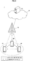
- FIG. 1 is an illustrative diagram illustrating an example of the general configuration of the communication system 1.
- the communication system 1 includes a base station 10, a management node 20, and a communication apparatus 100.
- the base station 10 performs wireless communication with an apparatus located within the communication area (i.e., a cell) of the base station 10. For example, when the communication apparatus 100 is located within the communication area, the base station 10 performs wireless communication with the communication apparatus 100.
- the management node 20 performs management involved with wireless communication.
- the management node 20 is a node in a mobile communication network including the base station 10. More specifically, for example, the management node 20 is a core network node located within a core network 30.
- the communication apparatus 100 performs wireless communication.
- the communication apparatus 100 when located within the communication area (i.e., a cell) of the base station 10, performs wireless communication with the base station 10. Also, for example, the communication apparatus 100 performs wireless communication without routing via the base station 10.
- the communication apparatus 100 generates information related to data which is wirelessly transmitted or received without being routed via the base station 10 (hereinafter referred to as "data-related information"), and transmits the data-related information to a node which is not involved with the transmission or reception of the data.
- the node is the management node 20. Also, the communication apparatus 100 is involved with the transmission or reception of the data.
- the communication apparatus 100 performs D2D communication, and the data wirelessly transmitted or received without being routed via the base station 10 is data which is transmitted or received by D2D communication. This example will now be more specifically described with reference to FIG. 2 .
- FIG. 2 is an illustrative diagram for describing a first specific example of the communication apparatus 100.
- the communication apparatus 100 which is a terminal apparatus, and a terminal apparatus 41 are shown.
- the communication apparatus 100 performs D2D communication with the terminal apparatus 41.
- the communication apparatus 100 also generates data-related information related to data transmitted or received by D2D communication, and transmits the data-related information to the management node 20.
- the communication apparatus 100 may be either a source of data in D2D communication or a destination of data in D2D communication.
- management involved with D2D communication can be performed.
- the communication apparatus 100 performs wireless communication within a localized network (LN), and the data wirelessly transmitted or received without being routed via the base station 10 is data transmitted or received within an LN.
- LN localized network
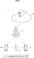
- FIG. 3 is an illustrative diagram for describing a second specific example of the communication apparatus 100.
- the communication apparatus 100, a terminal apparatus 43, and a terminal apparatus 45 which are a terminal apparatus are shown.
- the communication apparatus 100, the terminal apparatus 43, and the terminal apparatus 45 form an LN, and perform wireless communication within the LN.
- the communication apparatus 100 generates data-related information related to data transmitted or received within the LN, and transmits the data-related information to the management node 20.
- the communication apparatus 100 is a master node which performs control of wireless communication within the LN (e.g., scheduling of wireless communication within the LN, etc.).
- the terminal apparatus 43 and the terminal apparatus 45 are a slave node which performs wireless communication under the control of the master node. Note that when two slave nodes (the terminal apparatus 43 and the terminal apparatus 45) transmit and receive data, the communication apparatus 100 acquires information related to data transmitted or received from one of the two slave nodes.
- management involved with wireless communication within an LN can be performed.
- the communication apparatus 100 may be a slave node instead of a master node.
- the communication apparatus 100 may be a slave node which is a source of data, or a slave node which is a destination of data.
- the communication apparatus 100 communicates with another apparatus via a relay node, and the data wirelessly transmitted or received without being routed via the base station 10 is data which is transmitted or received via a relay node. This example will now be more specifically described with reference to FIG. 4 .
- FIG. 4 is an illustrative diagram for describing a third specific example of the communication apparatus 100.
- the communication apparatus 100 which is a terminal apparatus, a relay node 51, and a terminal apparatus 53 are shown.
- the communication apparatus 100 communicates with the terminal apparatus 53 via the relay node 51.
- the communication apparatus 100 generates data-related information related to data transmitted or received via the relay node 51, and transmits the data-related information to the management node 20.
- the communication apparatus 100 may be either a source of data, or a destination of data in D2D communication.
- management involved with wireless communication via a relay node can be performed.
- the communication apparatus 100 is a relay node, and the data wirelessly transmitted or received without being routed via the base station 10 is data which is transmitted or received via a relay node (i.e., the communication apparatus 100).
- a relay node i.e., the communication apparatus 100
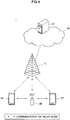
- FIG. 5 is an illustrative diagram for describing a fourth specific example of the communication apparatus 100.
- the communication apparatus 100 which is a relay node, a terminal apparatus 55, and a terminal apparatus 57 are shown.
- the communication apparatus 100 performs relay between the terminal apparatus 55 and the terminal apparatus 57.
- the communication apparatus 100 generates data-related information related to data transmitted or received via the communication apparatus 100, which is a relay node, and transmits the data-related information to the management node 20.
- management involved with wireless communication via a relay node can be performed.
- the data wirelessly transmitted or received without being routed via the base station 10 is transmitted or received according to the same wireless communication scheme as that which is used by the base station 10.
- the wireless communication scheme is a multiple access scheme, such as orthogonal frequency division multiple access (OFDMA), single carrier frequency division multiple access (SC-FDMA), frequency division multiple access (FDMA), or time division multiple access (TDMA).
- the wireless communication scheme may be a multiplexing scheme, such as orthogonal frequency division multiplexing (OFDM), frequency division multiplexing (FDM), or time division multiplexing (TDM).
- two communication apparatuses 100 may generate data-related information, and transmit the data-related information to the management node 20.
- one communication apparatus 100 which is a source of data and another communication apparatus 100 which is a destination of the data, may each generate data-related information related to the data, and transmit the data-related information to the management node 20.
- the reliability of data-related information can be improved.
- data-related information transmitted by one communication apparatus 100 fails to reach the management node 20
- data-related information transmitted by another communication apparatus 100 may reach the management node 20.
- the data-related information transmitted by one communication apparatus 100 is information generated without authorization, the data-related information can be verified using data-related information transmitted by another communication apparatus 100.
- FIG. 6 is a block diagram illustrating an example of a configuration of the communication apparatus 100.
- the communication apparatus 100 includes an antenna unit 110, a radio communication unit 120, a storage unit 130, and a processing unit 140.
- the antenna unit 110 radiates a signal output by the radio communication unit 120, as radio waves, into space.
- the antenna unit 110 also converts radio waves in space into a signal, and outputs the signal to the radio communication unit 120.
- the radio communication unit 120 performs wireless communication. For example, the radio communication unit 120 transmits a signal or receives a signal.
- the radio communication unit 120 performs wireless communication with the base station 10. More specifically, for example, the radio communication unit 120, when located within the communication area (i.e., a cell) of the base station 10, receives a downlink signal transmitted by the base station 10, and transmits an uplink signal to the base station 10.
- the radio communication unit 120 when located within the communication area (i.e., a cell) of the base station 10, receives a downlink signal transmitted by the base station 10, and transmits an uplink signal to the base station 10.
- the radio communication unit 120 performs wireless communication with a second apparatus other than the base station 10. More specifically, for example, the radio communication unit 120 receives a signal from the second apparatus, and transmits a signal to the second apparatus.
- the storage unit 130 temporarily or permanently stores a program and data for operating the communication apparatus 100.
- the processing unit 140 provides various functions of the communication apparatus 100.
- the processing unit 140 includes an information generation unit 141 and a transmission control unit 143.
- the information generation unit 141 generates information related to data (i.e., data-related information) which is wirelessly transmitted or received without being routed via the base station 10.
- the data-related information is information for charging for the transmission or reception of the data.
- the data-related information contains information indicating at least one of the source and destination of the data. More specifically, for example, the data-related information is addresses (e.g., Internet protocol (IP) addresses, media access control (MAC) addresses, etc.) of the source and destination of the data, or other identification information of the source and destination of the data. Such information can, for example, be used to identify an apparatus or user to be charged.
- addresses e.g., Internet protocol (IP) addresses, media access control (MAC) addresses, etc.
- IP Internet protocol
- MAC media access control
- the data-related information contains information indicating the amount of radio resources used for the transmission or reception of data. More specifically, for example, the data-related information contains, as the information indicating the amount of radio resources, the number of resource blocks, the number of slots, the number of sub-frames, and the like. Such information can, for example, be used to charge on the basis of the amount of radio resources used.
- the data-related information may contain information indicating the amount of data instead of or in addition to the information indicating the amount of radio resources. More specifically, for example, the data-related information may contain, as the information indicating the amount data, information indicating a data size, the amount of packets, etc. Such information can, for example, be used to charge on the basis of the amount of data transmitted or received.
- a communication error (e.g., an error on a physical link) may occur during transmission or reception of data. Therefore, there may be a number of techniques of calculating the amount of radio resources or the amount of data.
- the amount of all radio resources used for transmission or reception of data (or the amount of all data transmitted or received) is calculated irrespective of whether a communication error occurs. Thereafter, data-related information containing information indicating the amount of all radio resources (or the amount of all data) is generated.
- the amount of radio resources used when a communication error does not occur is calculated. Thereafter, data-related information containing information indicating the radio resource amount (or the data amount) is generated.
- the second calculation technique for example, a situation where the amount of charge exceeds what is expected by the user, due to the occurrence of a communication error, can be avoided.
- the scheme of retransmission control e.g., hybrid automatic repeat-request (HARQ)
- HARQ hybrid automatic repeat-request
- CRC cyclic redundancy check
- the communication apparatus 100 when being a source of data, calculates the amount of radio resources on the basis of ACK/NACK of HARQ. Specifically, the communication apparatus 100, when receiving ACK, adds the amount of radio resources used in transmission of data corresponding to the ACK, to the calculated amount of radio resources. Meanwhile, the communication apparatus 100, when receiving NACK, does not add the amount of radio resources used in transmission of data corresponding to NACK, to the calculated amount of radio resources. The communication apparatus 100, when receiving neither ACK nor NACK, does not add the amount of radio resources used in transmission of corresponding data, to the calculated amount of radio resources. Although an example of the amount of radio resources has been described, the amount of data is calculated in a similar fashion.
- the communication apparatus 100 when being a destination of data, calculates the amount of radio resources on the basis of the result of error detection by CRC. Specifically, when an error has not been detected by CRC (i.e., CRC is successful), the communication apparatus 100 adds the amount of radio resources used in transmission of data corresponding to the CRC, to the calculated amount of radio resources. Meanwhile, when an error has been detected by CRC, the communication apparatus 100 does not add the amount of radio resources used in transmission of data corresponding to the CRC, to the calculated amount of radio resources.
- data-related information is generated, and transmitted as described below, each time it is found that a communication error has not occurred. For example, each time the communication apparatus 100 receives ACK, the communication apparatus 100, when being a source of data, may calculate the amount of radio resources used in transmission of data corresponding to the ACK (or the amount of the data), and generate and transmit data-related information containing information indicating that amount. Alternatively, each time CRC is successful, the communication apparatus 100, when being a destination of data, calculates the amount of radio resources used in transmission of data corresponding to the CRC (or the amount of the data), and generate and transmit data-related information containing information indicating that amount.
- the data-related information may contain other information.
- the data-related information may contain information related to an application corresponding to the data (e.g., information indicating the type of the application, information indicating the application, etc.).
- the data-related information may contain a communication form (e.g., D2D communication, communication within an LN, relay, etc.).
- the data-related information is information for charging for the transmission or reception of the data.
- Such data-related information can, for example, be used to manage charging for wireless communication which is performed without routing via the base station 10.
- the data-related information is information for lawful interception (LI).
- LI lawful interception
- the data-related information contains information containing at least one of the source and destination of the data. More specifically, for example, the data-related information is addresses (e.g., an IP address, a MAC address, etc.) of the source and destination of the data, or other identification information of the source and destination of the data. Such information can, for example, be used to identify an apparatus or user which transmits or receives data.
- addresses e.g., an IP address, a MAC address, etc.
- the data-related information contains the data (i.e., data transmitted or received without being routed via the base station 10). Such information can, for example, be used to check transmitted or received data itself.
- the data-related information may contain other information.
- the data-related information may contain information related to an application corresponding to the data.
- the data-related information may contain information indicating a communication form.
- the data-related information is information for LI.
- data-related information can, for example, be used to perform lawful interception (LI) for wireless communication which is performed without routing via the base station 10.
- LI lawful interception
- the information generation unit 141 may generate the data-related information in various units. For example, the information generation unit 141 may generate the data-related information on a packet-by-packet basis, or may generate the data-related information about data which is transmitted or received during a predetermined period of time, or may generate the data-related information which is transmitted or received during a period of time between the start and end of a session (or connection).
- the transmission control unit 143 controls transmission of the data-related information to a node which is not involved in the transmission or reception of the data (i.e., data transmitted or received without being routed via the base station 10).
- the node which is not involved in the transmission or reception of the data i.e., a node which is a destination of the data-related information
- the node which is not involved in the transmission or reception of the data is the management node 20.
- the data-related information is information for charging for the transmission or reception of the data.
- the management node 20 is a node which manages charging. More specifically, for example, the management node 20 is a policy and charging rule function (PCRF).
- PCRF policy and charging rule function
- the data-related information is information for lawful interception (LI).
- the management node 20 is a node for performing a process for LI.
- the process includes, for example, storing the information for LI to a storage device.
- the storage device may be a storage device included in the management node 20, or a storage device included in another node.
- the management node 20 is a packet data network (PDN) gateway (P-GW).
- PDN packet data network gateway
- the data-related information is transmitted to the management node 20 via the base station 10.
- the base station 10 A specific example of this will now be described with reference to FIG. 7 .
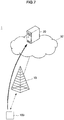
- FIG. 7 is an illustrative diagram for describing a first example of a transmission path for data-related information.
- the base station 10, the management node 20, and the communication apparatus 100 are shown.
- the management node 20 is located in the core network 30, and the communication apparatus 100 transmits the data-related information to the management node 20 via the base station 10 and the core network 30.
- the transmission path is not limited to this example.
- the data-related information may be transmitted to the management node 20 without being routed via the base station 10 instead of being transmitted to the management node 20 via the base station 10.
- a specific example of this will now be described with reference to FIG. 8 .
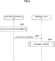
- FIG. 8 is an illustrative diagram for describing a second example of the transmission path for the data-related information.
- the base station 10, the management node 20, and the communication apparatus 100 are shown.
- the management node 20 is located in the core network 30, and the communication apparatus 100 transmits the data-related information to the management node 20 via an external network 60 and the core network 30.
- the external network 60 includes, for example, the Internet.
- the communication apparatus 100 connects to a wired LAN or a wireless LAN, and transmits the data-related information to the management node 20 via the Internet.
- the transmission control unit 143 may generate control information for a mobile communication network containing the data-related information, and cause the radio communication unit 120 to transmit the control information.
- the transmission control unit 143 may trigger transmission of the data-related information. Specifically, the transmission control unit 143 may instruct another component (e.g., another component included in the processing unit 140) of the communication apparatus 100 to transmit the data-related information.
- another component e.g., another component included in the processing unit 140
- the data-related information is thus generated and transmitted.
- management involved with wireless communication without routing via the base station 10 can be performed.
- FIG. 9 is a sequence diagram illustrating a first example of a general flow of the entire process. This process is performed after transmission or reception of data without routing via the base station 10.
- the communication apparatus 100 generates information related to data (i.e., data-related information) which is wirelessly transmitted or received without being routed via the base station 10 (S310).
- the communication apparatus 100 transmits the data-related information to the management node 20, and the management node 20 receives the data-related information (S320).
- the management node 20 executes a management process using the data-related information (S400).
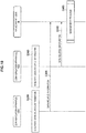
- FIG. 10 is a sequence diagram illustrating a second example of a general flow of the entire process. The process is executed after transmission or reception of data without routing via the base station 10.
- a communication apparatus 100A and a communication apparatus 100B each generate information related to data (i.e., data-related information) which is wirelessly transmitted or received without being routed via the base station 10 (S330, S340).
- data i.e., data-related information
- the communication apparatus 100A and the communication apparatus 100B each transmit the data-related information to the management node 20, and the management node 20 receives the data-related information (S350, S360).
- the management node 20 executes a management process using the data-related information (S400).
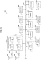
- FIG. 11 is a flowchart illustrating an example of a general flow of a first example of the management process.
- the first example of the management process is a process for charging management.
- the management node 20 acquires data-related information transmitted by the communication apparatus 100 (S401). Thereafter, the management node 20 checks the source and destination of data which is transmitted or received without being routed via the base station 10a, an application corresponding to the data, and the amount of radio resources used in the transmission or reception of the data (S403, S405, S407).
- the management node 20 when determining to update charging information (S409: YES), determines a node for which charging information is to be updated (S411), and updates the charging information of the node (S413).
- the management node 20 when determining to update policy information related to charging (S415: YES), determines a node for which policy information is to be updated (S417), and updates the policy information of the node (S419). Thereafter, the process is ended.
- FIG. 12 is a flowchart illustrating an example of a general flow of a second example of the management process.
- the second example of the management process is a process for LI.
- the management node 20 acquires data-related information transmitted by the communication apparatus 100 (S431).
- the management node 20 checks the source of data which is transmitted or received without being routed via the base station 10 (S433). Thereafter, the management node 20, when determining that the source is to be subjected to LI (S435: YES), executes a process requested for the source to be subjected to LI (S437).
- the process includes storing information for LI (e.g., the data and the source and destination of the data, etc.) to a storage device.
- the management node 20 also checks the destination of the data (S439). Thereafter, the management node 20, when determining that the destination is to be subjected to LI (S441: YES), executes a process requested for the destination to be subjected to LI (S443). The process includes storing information for LI to a storage device. Thereafter, the process is ended.
- a frequency band used in wireless communication which is performed without routing via a base station may be the same as or different from a frequency band used in wireless communication with a base station.
- the frequency band is, for example, a component carrier for a cellular network, a channel for wireless LAN, or the like.
- a frequency band used in wireless communication which is performed without routing via a base station (e.g., D2D communication, communication in an LN, etc.) (hereinafter referred to as a "second frequency band") is different from a frequency band used in wireless communication with a base station (hereinafter referred to as a "first frequency band”)).
- the second frequency band is a band having higher frequencies than those of the first frequency band.
- FIG. 13 is an illustrative diagram for describing an example of the frequency bands.
- a frequency band F1 and a frequency band F2 are shown.
- the frequency band F1 is a frequency band which is used in wireless communication with the base station 10
- the frequency band F2 is a frequency band which is used in wireless communication which is performed without routing via the base station 10.
- the frequency band F1 is a band having lower frequencies than those of the frequency band F2.
- the second frequency band (a band having higher frequencies) is used to wirelessly transmit or receive data without routing via the base station 10
- the first frequency band (a band having lower frequencies) is used to transmit information related to the data (i.e., data-related information) to the node 20.
- radio resources can be more effectively used. More specifically, for example, it is assumed that data-related information is transmitted to a base station which is located in a relatively far place. Therefore, the use of a band having lower frequencies (i.e., the first frequency band), which are less attenuated, may reduce the possibility that a communication error occurs in transmission of the data-related information. In other words, radio resources are more effectively used. For example, it is also assumed that data is transmitted or received between apparatuses located relatively close to each other. Therefore, for example, transmission may be performed by using a band having higher frequencies (i.e., the second frequency band), which are significantly attenuated. Also, in the highfrequency band, radio resources having a wider band width can be provided. In other words, radio resources can be more effectively used.
- Radio resources for transmission of data-related information (hereinafter referred to as “first radio resources") and radio resources for transmission of data (hereinafter referred to as “second radio resources”) are allocated (e.g. by the base station 10).
- the first radio resources and the second radio resources are allocated as a set of radio resources.
- the first radio resources radio resources for transmission of data-related information
- the second radio resources radio resources for transmission of data
- transmission of data-related information is allowed. Note that, in this case, data-related information is generated by the time when allocation of radio resources is requested.
- the first radio resources and the second radio resources are allocated so that there is a predetermined offset in time between the first radio resources and the second radio resources. A specific example of this will now be described with reference to FIG. 14 .
- FIG. 14 is an illustrative diagram for describing an example of the first radio resources and the second radio resources.
- the radio resources of the frequency band F1 and the radio resources of the frequency band F2 are shown.
- the radio resources of time T1 of the frequency band F2 are allocated.
- the radio resources for transmission of corresponding data-related information i.e., the first radio resources
- the radio resources of time T2 of the frequency band F1 are allocated.
- the time T2 is time later than the time T1 by a predetermined offset. For example, thus, there is a predetermined offset (T2 - T1) in time between the first radio resources and the second radio resources.
- the predetermined offset may be represented in units of sub-frames, slots, or the like in a cellular network.
- the predetermined offset may be represented in units of inter-frames (IF) or the like in a wireless LAN.
- the predetermined offset may be represented in units of seconds or the like.
- the length of the predetermined offset may, for example, be previously determined as a fixed value in a communication system, or may be set as appropriate in a communication system.
- the communication apparatus 100 (or other apparatuses) may be notified of the length of the predetermined offset at any timing (e.g., regularly). This notification may be performed by any of broadcast, multicast, and unicast.
- a the communication apparatus 100 may be implemented as a mobile terminal such as a smartphone, a tablet personal computer (PC), a notebook PC, a portable game terminal, a portable/dongle type mobile router, and a digital camera, or an in-vehicle terminal such as a car navigation apparatus.
- the communication apparatus 100 may also be implemented as a terminal (that is also referred to as a machine type communication (MTC) terminal) that performs machine-to-machine (M2M) communication.
- MTC machine type communication
- M2M machine-to-machine
- the communication apparatus 100 may be implemented as a relay node or an apparatus included in a relay node.
- at least a portion of the components of the communication apparatus 100 may be implemented as a module (e.g., an integrated circuit module including a single die) mounted on these terminals or apparatuses.
- FIG. 15 is a block diagram illustrating an example of a general configuration of a smartphone 900 to which the technology of the present disclosure may be applied.
- the smartphone 900 includes a processor 901, a memory 902, a storage 903, an external connection interface 904, a camera 906, a sensor 907, a microphone 908, an input device 909, a display device 910, a speaker 911, a radio communication interface 912, one or more antenna switches 915, one or more antennas 916, a bus 917, a battery 918, and an auxiliary controller 919.
- the processor 901 may be, for example, a CPU or a system on a chip (SoC), and controls functions of an application layer and another layer of the smartphone 900.
- the memory 902 includes RAM and ROM, and stores a program that is executed by the processor 901, and data.
- the storage 903 may include a storage medium such as a semiconductor memory and a hard disk.
- the external connection interface 904 is an interface for connecting an external device such as a memory card and a universal serial bus (USB) device to the smartphone 900.
- USB universal serial bus
- the camera 906 includes an image sensor such as a charge coupled device (CCD) and a complementary metal oxide semiconductor (CMOS), and generates a captured image.
- the sensor 907 may include a group of sensors such as a measurement sensor, a gyro sensor, a geomagnetic sensor, and an acceleration sensor.
- the microphone 908 converts sounds that are input to the smartphone 900 to audio signals.
- the input device 909 includes, for example, a touch sensor configured to detect touch onto a screen of the display device 910, a keypad, a keyboard, a button, or a switch, and receives an operation or an information input from a user.
- the display device 910 includes a screen such as a liquid crystal display (LCD) and an organic light-emitting diode (OLED) display, and displays an output image of the smartphone 900.
- the speaker 911 converts audio signals that are output from the smartphone 900 to sounds.
- the radio communication interface 912 supports any cellular communication scheme such as LTE and LTE-Advanced, and performs radio communication.
- the radio communication interface 912 may typically include, for example, a BB processor 913 and an RF circuit 914.
- the BB processor 913 may perform, for example, encoding/decoding, modulating/demodulating, and multiplexing/demultiplexing, and performs various types of signal processing for radio communication.
- the RF circuit 914 may include, for example, a mixer, a filter, and an amplifier, and transmits and receives radio signals via the antenna 916.
- the radio communication interface 912 may also be a one chip module that has the BB processor 913 and the RF circuit 914 integrated thereon.
- the radio communication interface 912 may include the multiple BB processors 913 and the multiple RF circuits 914, as illustrated in FIG. 15 .
- FIG. 15 illustrates the example in which the radio communication interface 912 includes the multiple BB processors 913 and the multiple RF circuits 914, the radio communication interface 912 may also include a single BB processor 913 or a single RF circuit 914.
- the radio communication interface 912 may support another type of radio communication scheme such as a short-distance wireless communication scheme, a near field communication scheme, and a radio local area network (LAN) scheme.
- the radio communication interface 912 may include the BB processor 913 and the RF circuit 914 for each radio communication scheme.
- Each of the antenna switches 915 switches connection destinations of the antennas 916 among multiple circuits (such as circuits for different radio communication schemes) included in the radio communication interface 912.
- Each of the antennas 916 includes a single or multiple antenna elements (such as multiple antenna elements included in an MIMO antenna), and is used for the radio communication interface 912 to transmit and receive radio signals.
- the smartphone 900 may include the multiple antennas 916, as illustrated in FIG. 15 . Although FIG. 15 illustrates the example in which the smartphone 900 includes the multiple antennas 916, the smartphone 900 may also include a single antenna 916.
- the smartphone 900 may include the antenna 916 for each radio communication scheme.
- the antenna switches 915 may be omitted from the configuration of the smartphone 900.
- the bus 917 connects the processor 901, the memory 902, the storage 903, the external connection interface 904, the camera 906, the sensor 907, the microphone 908, the input device 909, the display device 910, the speaker 911, the radio communication interface 912, and the auxiliary controller 919 to each other.
- the battery 918 supplies power to blocks of the smartphone 900 illustrated in FIG. 15 via feeder lines, which are partially shown as dashed lines in the figure.
- the auxiliary controller 919 operates a minimum necessary function of the smartphone 900, for example, in a sleep mode.
- the information generation unit 141 and the transmission control unit 143 described with reference to FIG. 6 may be implemented in the processor 901 or the auxiliary controller 919. Alternatively, at least a portion of these components may be implemented in the radio communication interface 912. As an example, the smartphone 900 may include a module including the processor 901, the auxiliary controller 919, and/or a portion (e.g., the BB processor 913) or the entirety of the radio communication interface 912. In this module, the information generation unit 141 and the transmission control unit 143 may be implemented.
- the module may store a program for causing the processor to function as the information generation unit 141 and the transmission control unit 143 (in other words, a program for causing the processor to execute operations of the information generation unit 141 and the transmission control unit 143), and execute the program.
- a program for causing the processor to function as the information generation unit 141 and the transmission control unit 143 may be installed in the smartphone 900, and executed by the processor 901, the auxiliary controller 919, and/or the radio communication interface 912 (e.g., the BB processor 913).
- the smartphone 900 or the module may be provided as an apparatus including the information generation unit 141 and the transmission control unit 143, and a program for causing a processor to function as the information generation unit 141 and the transmission control unit 143 may be provided.
- a readable storage medium storing the program may also be provided.
- FIG. 16 is a block diagram illustrating an example of a general configuration of a car navigation apparatus 920 to which the technology of the present disclosure may be applied.
- the car navigation apparatus 920 includes a processor 921, a memory 922, a global positioning system (GPS) module 924, a sensor 925, a data interface 926, a content player 927, a storage medium interface 928, an input device 929, a display device 930, a speaker 931, a radio communication interface 933, one or more antenna switches 936, one or more antennas 937, and a battery 938.
- GPS global positioning system
- the processor 921 may be, for example, a CPU or a SoC, and controls a navigation function and another function of the car navigation apparatus 920.
- the memory 922 includes RAM and ROM, and stores a program that is executed by the processor 921, and data.
- the GPS module 924 uses GPS signals received from a GPS satellite to measure a position (such as latitude, longitude, and altitude) of the car navigation apparatus 920.
- the sensor 925 may include a group of sensors such as a gyro sensor, a geomagnetic sensor, and an air pressure sensor.
- the data interface 926 is connected to, for example, an in-vehicle network 941 via a terminal that is not shown, and acquires data generated by the vehicle, such as vehicle speed data.
- the content player 927 reproduces content stored in a storage medium (such as a CD and a DVD) that is inserted into the storage medium interface 928.
- the input device 929 includes, for example, a touch sensor configured to detect touch onto a screen of the display device 930, a button, or a switch, and receives an operation or an information input from a user.
- the display device 930 includes a screen such as a LCD or an OLED display, and displays an image of the navigation function or content that is reproduced.
- the speaker 931 outputs sounds of the navigation function or the content that is reproduced.
- the radio communication interface 933 supports any cellular communication scheme such as LET and LTE-Advanced, and performs radio communication.
- the radio communication interface 933 may typically include, for example, a BB processor 934 and an RF circuit 935.
- the BB processor 934 may perform, for example, encoding/decoding, modulating/demodulating, and multiplexing/demultiplexing, and performs various types of signal processing for radio communication.
- the RF circuit 935 may include, for example, a mixer, a filter, and an amplifier, and transmits and receives radio signals via the antenna 937.
- the radio communication interface 933 may be a one chip module having the BB processor 934 and the RF circuit 935 integrated thereon.
- the radio communication interface 933 may include the multiple BB processors 934 and the multiple RF circuits 935, as illustrated in FIG. 16 .
- FIG. 16 illustrates the example in which the radio communication interface 933 includes the multiple BB processors 934 and the multiple RF circuits 935, the radio communication interface 933 may also include a single BB processor 934 or a single RF circuit 935.
- the radio communication interface 933 may support another type of radio communication scheme such as a short-distance wireless communication scheme, a near field communication scheme, and a radio LAN scheme.
- the radio communication interface 933 may include the BB processor 934 and the RF circuit 935 for each radio communication scheme.
- Each of the antenna switches 936 switches connection destinations of the antennas 937 among multiple circuits (such as circuits for different radio communication schemes) included in the radio communication interface 933.
- Each of the antennas 937 includes a single or multiple antenna elements (such as multiple antenna elements included in an MIMO antenna), and is used for the radio communication interface 933 to transmit and receive radio signals.
- the car navigation apparatus 920 may include the multiple antennas 937, as illustrated in FIG. 16 . Although FIG. 16 illustrates the example in which the car navigation apparatus 920 includes the multiple antennas 937, the car navigation apparatus 920 may also include a single antenna 937.
- the car navigation apparatus 920 may include the antenna 937 for each radio communication scheme.
- the antenna switches 936 may be omitted from the configuration of the car navigation apparatus 920.
- the battery 938 supplies power to blocks of the car navigation apparatus 920 illustrated in FIG. 16 via feeder lines that are partially shown as dashed lines in the figure.
- the battery 938 accumulates power supplied form the vehicle.
- the information generation unit 141 and the transmission control unit 143 described with reference to FIG. 6 may be implemented in the processor 921. Alternatively, at least a portion of these components may be implemented in the wireless communication interface 933. As an example, the car navigation apparatus 920 may include a module including the processor 921 and/or a portion (e.g., the BB processor 934) or the entirety of the radio communication interface 933. In this module, the information generation unit 141 and the transmission control unit 143 may be implemented.
- the module may store a program for causing the processor to function as the information generation unit 141 and the transmission control unit 143 (in other words, a program for causing the processor to execute operations of the information generation unit 141 and the transmission control unit 143), and execute the program.
- a program for causing the processor to function as the information generation unit 141 and the transmission control unit 143 may be installed in the car navigation apparatus 920, and executed by the processor 921 and/or the radio communication interface 933 (e.g., the BB processor 913).
- the car navigation apparatus 920 or the module may be provided as an apparatus including the information generation unit 141 and the transmission control unit 143, and a program for causing the processor to function as the information generation unit 141 and the transmission control unit 143 may be provided.
- a readable storage medium storing the program may also be provided.
- the technology of the present disclosure may also be implemented as an in-vehicle system (or a vehicle) 940 including one or more blocks of the car navigation apparatus 920, the in-vehicle network 941, and a vehicle module 942.
- the in-vehicle system (or a vehicle) 940 may be provided as an apparatus including the information generation unit 141 and the transmission control unit 143.
- the vehicle module 942 generates vehicle data such as vehicle speed, engine speed, and trouble information, and outputs the generated data to the in-vehicle network 941.
- the communication apparatus 100 includes the information generation unit 141 which generates data-related information related to data which is wirelessly transmitted or received without being routed via the base station 10, and the control unit which controls transmission of the data-related information to a node which is not involved in the transmission or reception of the data.
- the control unit which controls transmission of the data-related information to a node which is not involved in the transmission or reception of the data.
- the data is data which is transmitted or received by D2D communication.
- management involved in D2D communication can be performed.
- the data is data which is transmitted or received in an LN.
- management involved with wireless communication in an LN can be performed.
- the data is data which is transmitted or received via a relay node.
- management involved with wireless communication via a relay node can be performed.
- the data-related information is information for charging for the transmission or reception of the data.
- charging management for wireless communication without routing via the base station 10 can be performed.
- the data-related information is information for lawful interception (LI).
- LI lawful interception
- data which is transmitted or received without routing via a base station is transmitted or received according to the same wireless communication scheme as that which is used by the base station.
- the present disclosure is not limited to this example.
- the data may be transmitted or received according to a wireless communication scheme which is different from that which is used by the base station.
- a management node may be a node which is in a mobile communication network and is not located in a core network (e.g., a base station).
- a management node may be a node which is not a node in a mobile communication network, and is out of a mobile communication network.
- data-related information is information for charging for the transmission or reception of the data
- data-related information is information for lawful interception (LI)
- LI lawful interception
- processing steps in each process in this specification are not strictly limited to being executed in a time series following the sequence described in a flowchart.
- the processing steps in each process may be executed in a sequence that differs from a sequence described herein as a flowchart, and furthermore may be executed in parallel.
- a computer program for causing hardware such as a CPU, ROM, and RAM built into a device (a communication control device or a terminal device) to exhibit functions similar to each structural element of the foregoing devices.
- a storage medium having such a computer program stored therein may also be provided.
- an information processing device e.g., a processing circuit or chip
- memory storing such a computer program (e.g., ROM and RAM) and one or more processors capable of executing such a computer program (such as a CPU or DSP, for example) may also be provided.
Landscapes
- Engineering & Computer Science (AREA)
- Signal Processing (AREA)
- Computer Networks & Wireless Communication (AREA)
- Computer Security & Cryptography (AREA)
- Technology Law (AREA)
- Databases & Information Systems (AREA)
- Computer Hardware Design (AREA)
- Computing Systems (AREA)
- General Engineering & Computer Science (AREA)
- Business, Economics & Management (AREA)
- Accounting & Taxation (AREA)
- Mobile Radio Communication Systems (AREA)
Claims (7)
- Endgerätevorrichtung (100), die Folgendes umfasst:Mittel, ausgelegt zum Durchführen von drahtloser und direkter Kommunikation von Daten mit einer anderen Endgerätevorrichtung (41), ohne über eine Basisstation geroutet zu werden;Mittel, ausgelegt zum Erzeugen von Informationen zur Gebührenberechnung für die drahtlose und direkte Kommunikation mit der anderen Endgerätevorrichtung (41), ohne über die Basisstation (10) geroutet zu werden; wobei die Informationen zur Gebührenberechnung Funkressourceninformationen beinhalten, wobei die Funkressourceninformationen ferner Folgendes beinhalten:Informationen, die die Anzahl von Ressourcenblöcken, die für die drahtlose und direkte Kommunikation verwendet werden, angeben, undInformationen, die die Anzahl von Unterrahmen, die für die drahtlose und direkte Kommunikation verwendet werden, angeben; undMittel, ausgelegt zum Übertragen der Informationen zur Gebührenberechnung an einen Knoten (20), der nicht an der drahtlosen und direkten Kommunikation beteiligt ist.
- Endgerätevorrichtung (100) nach Anspruch 1,
wobei die drahtlose und direkte Kommunikation durch Vorrichtung-zu-Vorrichtung- bzw. D2D-Kommunikation durchgeführt wird. - Endgerätevorrichtung (100) nach einem der vorhergehenden Ansprüche,
wobei der Knoten (20), der nicht an der drahtlosen und direkten Kommunikation der Daten beteiligt ist, ein Knoten (20) zum Durchführen einer an einer drahtlosen Kommunikation beteiligten Verwaltung ist, insbesondere ein Knoten (20) in einem Mobilkommunikationsnetz, das eine Basisstation beinhaltet. - Endgerätevorrichtung (100) nach einem der vorhergehenden Ansprüche,
wobei der Knoten (10), der nicht an der drahtlosen und direkten Kommunikation der Daten beteiligt ist, ein Knoten (20) zum Durchführen einer Gebührenberechnungsverwaltung ist. - Endgerätevorrichtung (100) nach einem der vorhergehenden Ansprüche,
wobei die Informationen zur Gebührenberechnung Informationen beinhalten, die eine Quelle und/oder ein Ziel der Daten angeben. - Programm zum Bewirken, dass ein Prozessor Folgendes ausführt:Durchführen von drahtloser und direkter Kommunikation von Daten mit einer Endgerätevorrichtung (41), ohne über eine Basisstation (10) geroutet zu werden;Erzeugen von Informationen zur Gebührenberechnung für die drahtlose und direkte Kommunikation mit der Endgerätevorrichtung (41), ohne über die Basisstation (10) geroutet zu werden, wobei die Informationen zur Gebührenberechnung Funkressourceninformationen beinhalten, wobei die Funkressourceninformationen ferner Folgendes beinhalten:Informationen, die die Anzahl von Ressourcenblöcken, die für die drahtlose und direkte Kommunikation verwendet werden, angeben, undInformationen, die die Anzahl von Unterrahmen, die für die drahtlose und direkte Kommunikation verwendet werden, angeben; undÜbertragen der Informationen zur Gebührenberechnung an einen Knoten (20), der nicht an der drahtlosen und direkten Kommunikation beteiligt ist.
- Verfahren für eine Endgerätevorrichtung, wobei das Verfahren Folgendes umfasst:Durchführen von drahtloser und direkter Kommunikation von Daten mit einer Endgerätevorrichtung (41), ohne über eine Basisstation (10) geroutet zu werden;Erzeugen von Informationen zur Gebührenberechnung für die drahtlose und direkte Kommunikation mit der Endgerätevorrichtung (41), ohne über die Basisstation (10) geroutet zu werden, wobei die Informationen zur Gebührenberechnung Funkressourceninformationen beinhalten, wobei die Funkressourceninformationen ferner Folgendes beinhalten:Informationen, die die Anzahl von Ressourcenblöcken, die für die drahtlose und direkte Kommunikation verwendet werden, angeben, undInformationen, die die Anzahl von Unterrahmen, die für die drahtlose und direkte Kommunikation verwendet werden, angeben; undÜbertragen der Informationen zur Gebührenberechnung an einen Knoten (20), der nicht an der drahtlosen und direkten Kommunikation beteiligt ist.
Applications Claiming Priority (2)
| Application Number | Priority Date | Filing Date | Title |
|---|---|---|---|
| JP2014026313A JP2015154243A (ja) | 2014-02-14 | 2014-02-14 | 装置、プログラム及び方法 |
| PCT/JP2015/050679 WO2015122225A1 (ja) | 2014-02-14 | 2015-01-13 | 装置、プログラム及び方法 |
Publications (3)
| Publication Number | Publication Date |
|---|---|
| EP3107320A1 EP3107320A1 (de) | 2016-12-21 |
| EP3107320A4 EP3107320A4 (de) | 2017-10-18 |
| EP3107320B1 true EP3107320B1 (de) | 2021-09-01 |
Family
ID=53799973
Family Applications (1)
| Application Number | Title | Priority Date | Filing Date |
|---|---|---|---|
| EP15748903.0A Active EP3107320B1 (de) | 2014-02-14 | 2015-01-13 | Vorrichtung, programm und verfahren zur durchführung einer direkten kommunikation |
Country Status (11)
| Country | Link |
|---|---|
| US (4) | US9992666B2 (de) |
| EP (1) | EP3107320B1 (de) |
| JP (1) | JP2015154243A (de) |
| CN (2) | CN111314892B (de) |
| ES (1) | ES2889873T3 (de) |
| MX (1) | MX365681B (de) |
| RU (1) | RU2680256C1 (de) |
| SG (1) | SG11201606416TA (de) |
| TW (1) | TWI676375B (de) |
| WO (1) | WO2015122225A1 (de) |
| ZA (1) | ZA201603217B (de) |
Families Citing this family (5)
| Publication number | Priority date | Publication date | Assignee | Title |
|---|---|---|---|---|
| EP3361766B1 (de) | 2015-11-06 | 2020-03-25 | Huawei Technologies Co., Ltd. | Verfahren und vorrichtung zur bestimmung von funkressourcen und dienstserver |
| GB2562220A (en) * | 2017-05-05 | 2018-11-14 | Tcl Communication Ltd | Methods and devices associated with direct communications in a radio access network |
| WO2020166348A1 (ja) * | 2019-02-13 | 2020-08-20 | ソニー株式会社 | 移動体、通信方法、およびプログラム |
| JP6679130B2 (ja) * | 2019-04-04 | 2020-04-15 | ホアウェイ・テクノロジーズ・カンパニー・リミテッド | 通信方法および通信システム |
| WO2020239912A1 (en) * | 2019-05-28 | 2020-12-03 | Ipcom Gmbh & Co. Kg | Vehicle mounted communication node metering and accounting |
Citations (1)
| Publication number | Priority date | Publication date | Assignee | Title |
|---|---|---|---|---|
| GB2491114A (en) * | 2011-05-19 | 2012-11-28 | Renesas Mobile Corp | Direct device-to-device communication in a mobile communication system |
Family Cites Families (38)
| Publication number | Priority date | Publication date | Assignee | Title |
|---|---|---|---|---|
| JP3801526B2 (ja) * | 2002-04-30 | 2006-07-26 | 松下電器産業株式会社 | 無線送信装置及び無線受信装置 |
| US6963739B2 (en) * | 2002-10-21 | 2005-11-08 | Motorola, Inc. | Method and apparatus for providing information intercept in an ad-hoc wireless network |
| CN1622676A (zh) | 2003-11-28 | 2005-06-01 | 皇家飞利浦电子股份有限公司 | 在支持p2p模式的通信体系中用于提高系统容量的方法和装置 |
| CN1735223A (zh) * | 2004-08-10 | 2006-02-15 | 皇家飞利浦电子股份有限公司 | 用于离线点到点对等通信的计费方法和装置 |
| US8712883B1 (en) * | 2006-06-12 | 2014-04-29 | Roxbeam Media Network Corporation | System and method for dynamic quality-of-service-based billing in a peer-to-peer network |
| JP5045029B2 (ja) * | 2006-08-21 | 2012-10-10 | 富士通株式会社 | 無線基地局 |
| EP2056617A1 (de) | 2006-08-24 | 2009-05-06 | Panasonic Corporation | Kommunikationssystem, kommunikationsverfahren, funkendgerät, funkrelayeinrichtung und steuereinrichtung |
| US20090300207A1 (en) * | 2008-06-02 | 2009-12-03 | Qualcomm Incorporated | Pcc enhancements for ciphering support |
| US20110176531A1 (en) * | 2008-10-01 | 2011-07-21 | Telefonaktiebolaget L M Ericsson (Publ) | Handling of Local Breakout Traffic in a Home Base Station |
| US8977232B2 (en) * | 2009-01-29 | 2015-03-10 | Qualcomm Incorporated | Certified device-based accounting |
| US8620270B2 (en) * | 2009-10-06 | 2013-12-31 | Mosaid Technologies Incorporated | System and method providing interoperability between cellular and other wireless systems |
| US8570168B2 (en) * | 2009-10-08 | 2013-10-29 | Bringrr Systems, Llc | System, method and device to interrogate for the presence of objects |
| US20110103319A1 (en) | 2009-10-29 | 2011-05-05 | Qualcomm Incorporated | Access point scheduled peer-to-peer communication |
| US9276708B2 (en) * | 2009-12-21 | 2016-03-01 | Nokia Technologies Oy | Secondary system usage in multicarrier networks |
| KR20140008990A (ko) * | 2011-03-14 | 2014-01-22 | 휴렛-팩커드 디벨롭먼트 컴퍼니, 엘.피. | 연속 잉크 공급 장치, 시스템 및 방법 |
| US20120294163A1 (en) * | 2011-05-19 | 2012-11-22 | Renesas Mobile Corporation | Apparatus and Method for Direct Device-to-Device Communication in a Mobile Communication System |
| GB2491857B (en) * | 2011-06-14 | 2015-07-29 | Sca Ipla Holdings Inc | Wireless communications system and method |
| KR101815326B1 (ko) * | 2012-01-31 | 2018-01-04 | 삼성전자주식회사 | 디바이스 간 직접 통신을 기반으로 한 타겟 서비스 장치 및 방법 |
| US20130203380A1 (en) * | 2012-02-05 | 2013-08-08 | Institute For Information Industry | Network device, core network, direct mode communication system and lawful interception method thereof |
| GB2500720A (en) * | 2012-03-30 | 2013-10-02 | Nec Corp | Providing security information to establish secure communications over a device-to-device (D2D) communication link |
| KR102036778B1 (ko) * | 2012-04-20 | 2019-10-25 | 엘지전자 주식회사 | 무선 통신 시스템에서의 d2d 데이터 전송 방법 및 장치 |
| JP6360277B2 (ja) * | 2012-04-25 | 2018-07-18 | 株式会社Nttドコモ | 課金システム、課金装置及び課金方法 |
| US9826525B2 (en) | 2012-04-26 | 2017-11-21 | Industrial Technology Research Institute | Resource management method and apparatuses for device to device communications |
| US9240881B2 (en) * | 2012-04-30 | 2016-01-19 | Alcatel Lucent | Secure communications for computing devices utilizing proximity services |
| TWI532352B (zh) * | 2012-05-04 | 2016-05-01 | 財團法人資訊工業策進會 | 無演進封包核心直接通訊系統及其通訊連接方法 |
| TWI620459B (zh) * | 2012-05-31 | 2018-04-01 | 內數位專利控股公司 | 在蜂巢式通訊系統中賦能直鏈通訊排程及控制方法 |
| CN103517245B (zh) * | 2012-06-21 | 2018-02-13 | 中兴通讯股份有限公司 | 一种d2d通信的计费方法和系统 |
| CN104704906B (zh) * | 2012-09-28 | 2018-08-17 | 三星电子株式会社 | 在无线保真直连(wfd)网络环境中建立wfd连接的方法和系统 |
| US9532224B2 (en) * | 2012-11-05 | 2016-12-27 | Electronics And Telecommunications Research Institute | Method of device-to-device discovery and apparatus thereof |
| EP2947792B1 (de) * | 2013-01-16 | 2022-12-28 | LG Electronics Inc. | Verfahren zur kommunikation zwischen endgeräten und vorrichtung dafür |
| WO2014113073A1 (en) * | 2013-01-17 | 2014-07-24 | Intel IP Corporation | Device-to-device discovery with direct radio signals |
| JP2014171093A (ja) | 2013-03-04 | 2014-09-18 | Ntt Docomo Inc | 移動局 |
| EP3025404B1 (de) * | 2013-07-23 | 2021-06-23 | Nokia Technologies Oy | Abrechnungsverfahren, vorrichtungen und computerprogrammprodukte zum sicheren laden für d2d-dienst |
| US10172115B2 (en) * | 2013-08-09 | 2019-01-01 | Lg Electronics Inc. | Method and apparatus for conducting device-to-device communication in wireless communication system |
| WO2015060756A1 (en) * | 2013-10-23 | 2015-04-30 | Telefonaktiebolaget L M Ericsson (Publ) | A network node and method for handling cellular and d2d communications in a wireless communications network |
| US9572171B2 (en) * | 2013-10-31 | 2017-02-14 | Intel IP Corporation | Systems, methods, and devices for efficient device-to-device channel contention |
| WO2015069051A1 (ko) * | 2013-11-08 | 2015-05-14 | 엘지전자(주) | 무선 통신시스템에서 단말 간 직접통신을 수행하기 위한 자원할당 방법 및 장치 |
| US9585181B2 (en) * | 2014-05-09 | 2017-02-28 | Mediatek Inc. | Method for finding wireless device by Wi-Fi direct |
-
2014
- 2014-02-14 JP JP2014026313A patent/JP2015154243A/ja active Pending
-
2015
- 2015-01-13 CN CN202010087633.6A patent/CN111314892B/zh active Active
- 2015-01-13 US US15/036,739 patent/US9992666B2/en active Active
- 2015-01-13 CN CN201580007370.0A patent/CN105960810B/zh active Active
- 2015-01-13 MX MX2016010205A patent/MX365681B/es active IP Right Grant
- 2015-01-13 SG SG11201606416TA patent/SG11201606416TA/en unknown
- 2015-01-13 RU RU2016132161A patent/RU2680256C1/ru not_active IP Right Cessation
- 2015-01-13 ES ES15748903T patent/ES2889873T3/es active Active
- 2015-01-13 EP EP15748903.0A patent/EP3107320B1/de active Active
- 2015-01-13 WO PCT/JP2015/050679 patent/WO2015122225A1/ja active Application Filing
- 2015-02-03 TW TW104103568A patent/TWI676375B/zh not_active IP Right Cessation
-
2016
- 2016-05-12 ZA ZA2016/03217A patent/ZA201603217B/en unknown
-
2018
- 2018-05-02 US US15/969,467 patent/US10382949B2/en active Active
-
2019
- 2019-06-21 US US16/447,993 patent/US10911497B2/en active Active
-
2020
- 2020-12-28 US US17/134,513 patent/US20210120046A1/en not_active Abandoned
Patent Citations (1)
| Publication number | Priority date | Publication date | Assignee | Title |
|---|---|---|---|---|
| GB2491114A (en) * | 2011-05-19 | 2012-11-28 | Renesas Mobile Corp | Direct device-to-device communication in a mobile communication system |
Also Published As
| Publication number | Publication date |
|---|---|
| US10382949B2 (en) | 2019-08-13 |
| US20160262012A1 (en) | 2016-09-08 |
| WO2015122225A1 (ja) | 2015-08-20 |
| US20210120046A1 (en) | 2021-04-22 |
| MX2016010205A (es) | 2016-10-13 |
| CN105960810A (zh) | 2016-09-21 |
| CN105960810B (zh) | 2020-03-10 |
| US20190313243A1 (en) | 2019-10-10 |
| EP3107320A1 (de) | 2016-12-21 |
| US9992666B2 (en) | 2018-06-05 |
| US10911497B2 (en) | 2021-02-02 |
| SG11201606416TA (en) | 2016-09-29 |
| CN111314892A (zh) | 2020-06-19 |
| EP3107320A4 (de) | 2017-10-18 |
| ES2889873T3 (es) | 2022-01-14 |
| JP2015154243A (ja) | 2015-08-24 |
| RU2680256C1 (ru) | 2019-02-19 |
| TW201540020A (zh) | 2015-10-16 |
| US20180255453A1 (en) | 2018-09-06 |
| CN111314892B (zh) | 2023-08-22 |
| ZA201603217B (en) | 2017-04-26 |
| MX365681B (es) | 2019-06-10 |
| TWI676375B (zh) | 2019-11-01 |
Similar Documents
| Publication | Publication Date | Title |
|---|---|---|
| US11909688B2 (en) | Apparatus and method in wireless communication system, and computer-readable storage medium | |
| US20220110151A1 (en) | Base station-side and user equipment-side apparatuses and methods, and wireless communication system | |
| KR20210032272A (ko) | 멀티 액세스 에지 컴퓨팅(mec) 서비스 계약 형성 및 작업부하 실행 | |
| EP3554137B1 (de) | Endgerätevorrichtung, verfahren und aufzeichnungsmedium | |
| CN110771206B (zh) | 用户平面重定位方法和装置 | |
| US20210120046A1 (en) | Apparatus, program, and method | |
| EP3145268B1 (de) | Spektrumsverwaltungsvorrichtung | |
| EP3761679B1 (de) | Standortverfahren und zugehörige vorrichtung | |
| US20190058980A1 (en) | V2x communication method and apparatus | |
| WO2013155198A1 (en) | Interference notification in device-to-device communication | |
| CN110463333A (zh) | 用于处理指示同一子帧中的不同物理上行链路共享信道开始位置的上行链路准予的机制 | |
| KR20190131473A (ko) | 전자 디바이스 및 라디오 통신 방법 | |
| EP3627873B1 (de) | Frequenzspektrumverwaltungsvorrichtung und verfahren, frequenzspektrumkoordinationsvorrichtung und verfahren sowie elektronische vorrichtung | |
| US10356827B2 (en) | Apparatus, method, and program | |
| CN111556530A (zh) | 一种数据处理方法及upf单元 | |
| EP3739960A1 (de) | Basisstation, endgerätevorrichtung, verfahren und aufzeichnungsmedium |
Legal Events
| Date | Code | Title | Description |
|---|---|---|---|
| PUAI | Public reference made under article 153(3) epc to a published international application that has entered the european phase |
Free format text: ORIGINAL CODE: 0009012 |
|
| STAA | Information on the status of an ep patent application or granted ep patent |
Free format text: STATUS: REQUEST FOR EXAMINATION WAS MADE |
|
| 17P | Request for examination filed |
Effective date: 20160805 |
|
| AK | Designated contracting states |
Kind code of ref document: A1 Designated state(s): AL AT BE BG CH CY CZ DE DK EE ES FI FR GB GR HR HU IE IS IT LI LT LU LV MC MK MT NL NO PL PT RO RS SE SI SK SM TR |
|
| AX | Request for extension of the european patent |
Extension state: BA ME |
|
| DAX | Request for extension of the european patent (deleted) | ||
| A4 | Supplementary search report drawn up and despatched |
Effective date: 20170918 |
|
| RIC1 | Information provided on ipc code assigned before grant |
Ipc: H04W 40/02 20090101ALI20170912BHEP Ipc: H04W 8/24 20090101AFI20170912BHEP Ipc: H04M 15/00 20060101ALI20170912BHEP Ipc: H04W 8/00 20090101ALN20170912BHEP Ipc: H04M 3/22 20060101ALI20170912BHEP Ipc: H04W 12/02 20090101ALI20170912BHEP Ipc: H04W 88/04 20090101ALN20170912BHEP Ipc: H04L 29/06 20060101ALI20170912BHEP Ipc: H04W 76/02 20090101ALI20170912BHEP |
|
| STAA | Information on the status of an ep patent application or granted ep patent |
Free format text: STATUS: EXAMINATION IS IN PROGRESS |
|
| 17Q | First examination report despatched |
Effective date: 20190507 |
|
| STAA | Information on the status of an ep patent application or granted ep patent |
Free format text: STATUS: EXAMINATION IS IN PROGRESS |
|
| REG | Reference to a national code |
Ref country code: DE Ref legal event code: R079 Ref document number: 602015072864 Country of ref document: DE Free format text: PREVIOUS MAIN CLASS: H04W0008240000 Ipc: H04W0076140000 |
|
| RIC1 | Information provided on ipc code assigned before grant |
Ipc: H04W 40/02 20090101ALN20210217BHEP Ipc: H04W 8/00 20090101ALN20210217BHEP Ipc: H04L 29/06 20060101ALI20210217BHEP Ipc: H04W 88/04 20090101ALN20210217BHEP Ipc: H04W 24/02 20090101ALN20210217BHEP Ipc: H04M 15/00 20060101ALI20210217BHEP Ipc: H04W 76/14 20180101AFI20210217BHEP |
|
| GRAP | Despatch of communication of intention to grant a patent |
Free format text: ORIGINAL CODE: EPIDOSNIGR1 |
|
| STAA | Information on the status of an ep patent application or granted ep patent |
Free format text: STATUS: GRANT OF PATENT IS INTENDED |
|
| RIC1 | Information provided on ipc code assigned before grant |
Ipc: H04W 24/02 20090101ALN20210225BHEP Ipc: H04M 15/00 20060101ALI20210225BHEP Ipc: H04W 76/14 20180101AFI20210225BHEP Ipc: H04W 8/00 20090101ALN20210225BHEP Ipc: H04L 29/06 20060101ALI20210225BHEP Ipc: H04W 88/04 20090101ALN20210225BHEP Ipc: H04W 40/02 20090101ALN20210225BHEP |
|
| RIC1 | Information provided on ipc code assigned before grant |
Ipc: H04W 40/02 20090101ALN20210315BHEP Ipc: H04W 24/02 20090101ALN20210315BHEP Ipc: H04W 88/04 20090101ALN20210315BHEP Ipc: H04W 8/00 20090101ALN20210315BHEP Ipc: H04L 29/06 20060101ALI20210315BHEP Ipc: H04M 15/00 20060101ALI20210315BHEP Ipc: H04W 76/14 20180101AFI20210315BHEP |
|
| INTG | Intention to grant announced |
Effective date: 20210330 |
|
| GRAS | Grant fee paid |
Free format text: ORIGINAL CODE: EPIDOSNIGR3 |
|
| RAP3 | Party data changed (applicant data changed or rights of an application transferred) |
Owner name: SONY GROUP CORPORATION |
|
| GRAA | (expected) grant |
Free format text: ORIGINAL CODE: 0009210 |
|
| STAA | Information on the status of an ep patent application or granted ep patent |
Free format text: STATUS: THE PATENT HAS BEEN GRANTED |
|
| AK | Designated contracting states |
Kind code of ref document: B1 Designated state(s): AL AT BE BG CH CY CZ DE DK EE ES FI FR GB GR HR HU IE IS IT LI LT LU LV MC MK MT NL NO PL PT RO RS SE SI SK SM TR |
|
| REG | Reference to a national code |
Ref country code: GB Ref legal event code: FG4D |
|
| REG | Reference to a national code |
Ref country code: NL Ref legal event code: FP |
|
| REG | Reference to a national code |
Ref country code: CH Ref legal event code: EP Ref country code: AT Ref legal event code: REF Ref document number: 1427642 Country of ref document: AT Kind code of ref document: T Effective date: 20210915 |
|
| REG | Reference to a national code |
Ref country code: DE Ref legal event code: R096 Ref document number: 602015072864 Country of ref document: DE |
|
| REG | Reference to a national code |
Ref country code: IE Ref legal event code: FG4D |
|
| REG | Reference to a national code |
Ref country code: LT Ref legal event code: MG9D |
|
| REG | Reference to a national code |
Ref country code: ES Ref legal event code: FG2A Ref document number: 2889873 Country of ref document: ES Kind code of ref document: T3 Effective date: 20220114 |
|
| PG25 | Lapsed in a contracting state [announced via postgrant information from national office to epo] |
Ref country code: LT Free format text: LAPSE BECAUSE OF FAILURE TO SUBMIT A TRANSLATION OF THE DESCRIPTION OR TO PAY THE FEE WITHIN THE PRESCRIBED TIME-LIMIT Effective date: 20210901 Ref country code: BG Free format text: LAPSE BECAUSE OF FAILURE TO SUBMIT A TRANSLATION OF THE DESCRIPTION OR TO PAY THE FEE WITHIN THE PRESCRIBED TIME-LIMIT Effective date: 20211201 Ref country code: FI Free format text: LAPSE BECAUSE OF FAILURE TO SUBMIT A TRANSLATION OF THE DESCRIPTION OR TO PAY THE FEE WITHIN THE PRESCRIBED TIME-LIMIT Effective date: 20210901 Ref country code: NO Free format text: LAPSE BECAUSE OF FAILURE TO SUBMIT A TRANSLATION OF THE DESCRIPTION OR TO PAY THE FEE WITHIN THE PRESCRIBED TIME-LIMIT Effective date: 20211201 Ref country code: RS Free format text: LAPSE BECAUSE OF FAILURE TO SUBMIT A TRANSLATION OF THE DESCRIPTION OR TO PAY THE FEE WITHIN THE PRESCRIBED TIME-LIMIT Effective date: 20210901 Ref country code: SE Free format text: LAPSE BECAUSE OF FAILURE TO SUBMIT A TRANSLATION OF THE DESCRIPTION OR TO PAY THE FEE WITHIN THE PRESCRIBED TIME-LIMIT Effective date: 20210901 Ref country code: HR Free format text: LAPSE BECAUSE OF FAILURE TO SUBMIT A TRANSLATION OF THE DESCRIPTION OR TO PAY THE FEE WITHIN THE PRESCRIBED TIME-LIMIT Effective date: 20210901 |
|
| REG | Reference to a national code |
Ref country code: AT Ref legal event code: MK05 Ref document number: 1427642 Country of ref document: AT Kind code of ref document: T Effective date: 20210901 |
|
| PG25 | Lapsed in a contracting state [announced via postgrant information from national office to epo] |
Ref country code: PL Free format text: LAPSE BECAUSE OF FAILURE TO SUBMIT A TRANSLATION OF THE DESCRIPTION OR TO PAY THE FEE WITHIN THE PRESCRIBED TIME-LIMIT Effective date: 20210901 Ref country code: LV Free format text: LAPSE BECAUSE OF FAILURE TO SUBMIT A TRANSLATION OF THE DESCRIPTION OR TO PAY THE FEE WITHIN THE PRESCRIBED TIME-LIMIT Effective date: 20210901 Ref country code: GR Free format text: LAPSE BECAUSE OF FAILURE TO SUBMIT A TRANSLATION OF THE DESCRIPTION OR TO PAY THE FEE WITHIN THE PRESCRIBED TIME-LIMIT Effective date: 20211202 |
|
| PG25 | Lapsed in a contracting state [announced via postgrant information from national office to epo] |
Ref country code: AT Free format text: LAPSE BECAUSE OF FAILURE TO SUBMIT A TRANSLATION OF THE DESCRIPTION OR TO PAY THE FEE WITHIN THE PRESCRIBED TIME-LIMIT Effective date: 20210901 |
|
| PG25 | Lapsed in a contracting state [announced via postgrant information from national office to epo] |
Ref country code: IS Free format text: LAPSE BECAUSE OF FAILURE TO SUBMIT A TRANSLATION OF THE DESCRIPTION OR TO PAY THE FEE WITHIN THE PRESCRIBED TIME-LIMIT Effective date: 20220101 Ref country code: SM Free format text: LAPSE BECAUSE OF FAILURE TO SUBMIT A TRANSLATION OF THE DESCRIPTION OR TO PAY THE FEE WITHIN THE PRESCRIBED TIME-LIMIT Effective date: 20210901 Ref country code: SK Free format text: LAPSE BECAUSE OF FAILURE TO SUBMIT A TRANSLATION OF THE DESCRIPTION OR TO PAY THE FEE WITHIN THE PRESCRIBED TIME-LIMIT Effective date: 20210901 Ref country code: RO Free format text: LAPSE BECAUSE OF FAILURE TO SUBMIT A TRANSLATION OF THE DESCRIPTION OR TO PAY THE FEE WITHIN THE PRESCRIBED TIME-LIMIT Effective date: 20210901 Ref country code: PT Free format text: LAPSE BECAUSE OF FAILURE TO SUBMIT A TRANSLATION OF THE DESCRIPTION OR TO PAY THE FEE WITHIN THE PRESCRIBED TIME-LIMIT Effective date: 20220103 Ref country code: EE Free format text: LAPSE BECAUSE OF FAILURE TO SUBMIT A TRANSLATION OF THE DESCRIPTION OR TO PAY THE FEE WITHIN THE PRESCRIBED TIME-LIMIT Effective date: 20210901 Ref country code: CZ Free format text: LAPSE BECAUSE OF FAILURE TO SUBMIT A TRANSLATION OF THE DESCRIPTION OR TO PAY THE FEE WITHIN THE PRESCRIBED TIME-LIMIT Effective date: 20210901 Ref country code: AL Free format text: LAPSE BECAUSE OF FAILURE TO SUBMIT A TRANSLATION OF THE DESCRIPTION OR TO PAY THE FEE WITHIN THE PRESCRIBED TIME-LIMIT Effective date: 20210901 |
|
| REG | Reference to a national code |
Ref country code: DE Ref legal event code: R097 Ref document number: 602015072864 Country of ref document: DE |
|
| PLBE | No opposition filed within time limit |
Free format text: ORIGINAL CODE: 0009261 |
|
| STAA | Information on the status of an ep patent application or granted ep patent |
Free format text: STATUS: NO OPPOSITION FILED WITHIN TIME LIMIT |
|
| PG25 | Lapsed in a contracting state [announced via postgrant information from national office to epo] |
Ref country code: IT Free format text: LAPSE BECAUSE OF FAILURE TO SUBMIT A TRANSLATION OF THE DESCRIPTION OR TO PAY THE FEE WITHIN THE PRESCRIBED TIME-LIMIT Effective date: 20210901 Ref country code: DK Free format text: LAPSE BECAUSE OF FAILURE TO SUBMIT A TRANSLATION OF THE DESCRIPTION OR TO PAY THE FEE WITHIN THE PRESCRIBED TIME-LIMIT Effective date: 20210901 |
|
| 26N | No opposition filed |
Effective date: 20220602 |
|
| PG25 | Lapsed in a contracting state [announced via postgrant information from national office to epo] |
Ref country code: SI Free format text: LAPSE BECAUSE OF FAILURE TO SUBMIT A TRANSLATION OF THE DESCRIPTION OR TO PAY THE FEE WITHIN THE PRESCRIBED TIME-LIMIT Effective date: 20210901 Ref country code: MC Free format text: LAPSE BECAUSE OF FAILURE TO SUBMIT A TRANSLATION OF THE DESCRIPTION OR TO PAY THE FEE WITHIN THE PRESCRIBED TIME-LIMIT Effective date: 20210901 |
|
| REG | Reference to a national code |
Ref country code: CH Ref legal event code: PL |
|
| GBPC | Gb: european patent ceased through non-payment of renewal fee |
Effective date: 20220113 |
|
| REG | Reference to a national code |
Ref country code: BE Ref legal event code: MM Effective date: 20220131 |
|
| PG25 | Lapsed in a contracting state [announced via postgrant information from national office to epo] |
Ref country code: LU Free format text: LAPSE BECAUSE OF NON-PAYMENT OF DUE FEES Effective date: 20220113 Ref country code: GB Free format text: LAPSE BECAUSE OF NON-PAYMENT OF DUE FEES Effective date: 20220113 |
|
| PG25 | Lapsed in a contracting state [announced via postgrant information from national office to epo] |
Ref country code: BE Free format text: LAPSE BECAUSE OF NON-PAYMENT OF DUE FEES Effective date: 20220131 |
|
| PG25 | Lapsed in a contracting state [announced via postgrant information from national office to epo] |
Ref country code: LI Free format text: LAPSE BECAUSE OF NON-PAYMENT OF DUE FEES Effective date: 20220131 Ref country code: CH Free format text: LAPSE BECAUSE OF NON-PAYMENT OF DUE FEES Effective date: 20220131 |
|
| PG25 | Lapsed in a contracting state [announced via postgrant information from national office to epo] |
Ref country code: IE Free format text: LAPSE BECAUSE OF NON-PAYMENT OF DUE FEES Effective date: 20220113 |
|
| P01 | Opt-out of the competence of the unified patent court (upc) registered |
Effective date: 20230527 |
|
| PGFP | Annual fee paid to national office [announced via postgrant information from national office to epo] |
Ref country code: NL Payment date: 20231219 Year of fee payment: 10 Ref country code: FR Payment date: 20231219 Year of fee payment: 10 |
|
| PG25 | Lapsed in a contracting state [announced via postgrant information from national office to epo] |
Ref country code: HU Free format text: LAPSE BECAUSE OF FAILURE TO SUBMIT A TRANSLATION OF THE DESCRIPTION OR TO PAY THE FEE WITHIN THE PRESCRIBED TIME-LIMIT; INVALID AB INITIO Effective date: 20150113 |
|
| PGFP | Annual fee paid to national office [announced via postgrant information from national office to epo] |
Ref country code: ES Payment date: 20240202 Year of fee payment: 10 |
|
| PG25 | Lapsed in a contracting state [announced via postgrant information from national office to epo] |
Ref country code: MK Free format text: LAPSE BECAUSE OF FAILURE TO SUBMIT A TRANSLATION OF THE DESCRIPTION OR TO PAY THE FEE WITHIN THE PRESCRIBED TIME-LIMIT Effective date: 20210901 Ref country code: CY Free format text: LAPSE BECAUSE OF FAILURE TO SUBMIT A TRANSLATION OF THE DESCRIPTION OR TO PAY THE FEE WITHIN THE PRESCRIBED TIME-LIMIT Effective date: 20210901 |
|
| PGFP | Annual fee paid to national office [announced via postgrant information from national office to epo] |
Ref country code: DE Payment date: 20231219 Year of fee payment: 10 |