EP3107205A1 - Variable threshold current limiting circuit - Google Patents
Variable threshold current limiting circuit Download PDFInfo
- Publication number
- EP3107205A1 EP3107205A1 EP16174730.8A EP16174730A EP3107205A1 EP 3107205 A1 EP3107205 A1 EP 3107205A1 EP 16174730 A EP16174730 A EP 16174730A EP 3107205 A1 EP3107205 A1 EP 3107205A1
- Authority
- EP
- European Patent Office
- Prior art keywords
- current
- current threshold
- controller
- circuit
- output
- Prior art date
- Legal status (The legal status is an assumption and is not a legal conclusion. Google has not performed a legal analysis and makes no representation as to the accuracy of the status listed.)
- Granted
Links
Images

Classifications
-
- H—ELECTRICITY
- H02—GENERATION; CONVERSION OR DISTRIBUTION OF ELECTRIC POWER
- H02H—EMERGENCY PROTECTIVE CIRCUIT ARRANGEMENTS
- H02H3/00—Emergency protective circuit arrangements for automatic disconnection directly responsive to an undesired change from normal electric working condition with or without subsequent reconnection ; integrated protection
- H02H3/08—Emergency protective circuit arrangements for automatic disconnection directly responsive to an undesired change from normal electric working condition with or without subsequent reconnection ; integrated protection responsive to excess current
-
- H—ELECTRICITY
- H02—GENERATION; CONVERSION OR DISTRIBUTION OF ELECTRIC POWER
- H02H—EMERGENCY PROTECTIVE CIRCUIT ARRANGEMENTS
- H02H3/00—Emergency protective circuit arrangements for automatic disconnection directly responsive to an undesired change from normal electric working condition with or without subsequent reconnection ; integrated protection
- H02H3/006—Calibration or setting of parameters
-
- H—ELECTRICITY
- H02—GENERATION; CONVERSION OR DISTRIBUTION OF ELECTRIC POWER
- H02H—EMERGENCY PROTECTIVE CIRCUIT ARRANGEMENTS
- H02H7/00—Emergency protective circuit arrangements specially adapted for specific types of electric machines or apparatus or for sectionalised protection of cable or line systems, and effecting automatic switching in the event of an undesired change from normal working conditions
- H02H7/08—Emergency protective circuit arrangements specially adapted for specific types of electric machines or apparatus or for sectionalised protection of cable or line systems, and effecting automatic switching in the event of an undesired change from normal working conditions for dynamo-electric motors
- H02H7/0833—Emergency protective circuit arrangements specially adapted for specific types of electric machines or apparatus or for sectionalised protection of cable or line systems, and effecting automatic switching in the event of an undesired change from normal working conditions for dynamo-electric motors for electric motors with control arrangements
-
- H—ELECTRICITY
- H02—GENERATION; CONVERSION OR DISTRIBUTION OF ELECTRIC POWER
- H02H—EMERGENCY PROTECTIVE CIRCUIT ARRANGEMENTS
- H02H9/00—Emergency protective circuit arrangements for limiting excess current or voltage without disconnection
- H02H9/02—Emergency protective circuit arrangements for limiting excess current or voltage without disconnection responsive to excess current
-
- H—ELECTRICITY
- H02—GENERATION; CONVERSION OR DISTRIBUTION OF ELECTRIC POWER
- H02P—CONTROL OR REGULATION OF ELECTRIC MOTORS, ELECTRIC GENERATORS OR DYNAMO-ELECTRIC CONVERTERS; CONTROLLING TRANSFORMERS, REACTORS OR CHOKE COILS
- H02P29/00—Arrangements for regulating or controlling electric motors, appropriate for both AC and DC motors
- H02P29/02—Providing protection against overload without automatic interruption of supply
- H02P29/032—Preventing damage to the motor, e.g. setting individual current limits for different drive conditions
-
- H—ELECTRICITY
- H02—GENERATION; CONVERSION OR DISTRIBUTION OF ELECTRIC POWER
- H02H—EMERGENCY PROTECTIVE CIRCUIT ARRANGEMENTS
- H02H7/00—Emergency protective circuit arrangements specially adapted for specific types of electric machines or apparatus or for sectionalised protection of cable or line systems, and effecting automatic switching in the event of an undesired change from normal working conditions
- H02H7/08—Emergency protective circuit arrangements specially adapted for specific types of electric machines or apparatus or for sectionalised protection of cable or line systems, and effecting automatic switching in the event of an undesired change from normal working conditions for dynamo-electric motors
-
- H—ELECTRICITY
- H02—GENERATION; CONVERSION OR DISTRIBUTION OF ELECTRIC POWER
- H02H—EMERGENCY PROTECTIVE CIRCUIT ARRANGEMENTS
- H02H9/00—Emergency protective circuit arrangements for limiting excess current or voltage without disconnection
- H02H9/02—Emergency protective circuit arrangements for limiting excess current or voltage without disconnection responsive to excess current
- H02H9/025—Current limitation using field effect transistors
Definitions
- the present disclosure relates generally to electronics for utilization in a spacecraft, and more specifically to a current limiting circuit for the same.
- Motor controller circuits frequently include current limiters that are configured to monitor a current in the motor controller and disable or reduce the current when the current exceeds an overcurrent threshold. Such circuits protect the controller, the motor, and the overall system from excessive current that can occur during operation.
- the specific electrical system for any given application requires a current limit tailored to that specific application, as the amount of current that can be passed through a system without damaging the system varies depending on the specifications of the system itself.
- a current limiting circuit for a motor controller including: a comparator having a sensed current input, a current threshold input, and an overcurrent protection trip output, a variable resistance current threshold circuit connected to the current threshold input, and a first controller connected to the variable resistance current threshold circuit via a plurality of connections, the first controller being configured to control a voltage output of the variable resistance current threshold circuit.
- Also disclosed is a method for providing current limiting to a motor controller including: providing a sensed current to a comparator, generating a current threshold using a variable resistance resistor network, and providing the current threshold to the comparator, and comparing the sensed current to the current threshold and outputting a trip signal from the comparator when the sensed current exceeds the current threshold.
- a motor controller for a spacecraft including: a current limiting circuit including a comparator having a sensed current input, a current threshold input, and an overprotection trip output, and a variable resistance resistor network having a plurality sections of equivalent resistors, an output of the variable resistance network being connected to the current threshold input, and a programmable controller having a plurality of pin connections, each of the plurality of pin connections connected to a distinct node within the variable resistance resistor network, and each of the plurality of pin connections being operable to provide one of a zero volt output and a positive voltage output.
- each circuit element is further subjected to a substantial qualifications process to ensure that the element or component is sufficiently operable in extreme conditions, such as those present outside of the Earth's atmosphere. Any change in the design of the system requires the entire system to be re-qualified.
- Spacecraft applications are single or low production applications, meaning that only a single system, or a very limited number of systems, requiring a given current limit circuit will ever be built.
- application specific current limit circuits are expensive to produce.
- general current limiter circuits utilizing a digital controller to compare a sensed current value against a threshold are unsuitable for some spacecraft applications.
- Figure 1 schematically illustrates an example programmable current limiting circuit 10, capable of generating a variable current limiting threshold.
- the current limiting threshold generated by the programmable current limiting circuit 10 can be adjusted by a controller during operation without altering or replacing any of the analog current limiter circuit elements.
- the programmable current limiting circuit 10 includes a comparator 20 having a current threshold input 22 and a current sense input 24.
- the comparator 20 compares a voltage input received on the current sense input 24 against a voltage input received on the current threshold input 22 and outputs "high" (a positive voltage) on a comparator output 26 when the current sense input 24 exceeds the current threshold input 22.
- the output of the comparator 20 is provided to a current trip circuit 60 within the motor controller containing the current limit circuit 10. When the output of the comparator 20 is high, the current trip circuit 60 trips, and an overcurrent condition is prevented. Any known current trip circuit 60 can be utilized in conjunction with the system described herein.
- the current sense input 24 is a voltage value representative of a sensed current within the motor controller
- the current threshold input 22 is a voltage value representative of a current threshold.
- a resistor network 30 Connected to the current threshold input 22 of the comparator 20 is a resistor network 30 configured to provide a voltage to the current threshold input 22.
- the resistor network 30 is connected to a programmable controller 40 via multiple pin connections 42.
- Each of the multiple pin connections 42 can be set to output either zero volts or a positive voltage by the programmable controller 40.
- Each of the multiple pin connections 42 is connected to the resistor network 30 at different locations within the resistor network 30.
- the voltage output of the resistor network 30 is determined by which of the multiple pin connections 42 has a positive voltage at a given time. In this way, the programmable controller 40 can set, and alter, the current threshold for the current limiter circuit 10 by altering which of the pin connections 42 are outputting a positive voltage.
- the programmable controller 40 is a Field Programmable Gate Array (FPGA) controller. In alternative examples, any other type of programmable controller qualified for utilization in spacecraft can be utilized to the same effect. In yet further examples, the programmable controller 40 is a control element having excess pin outputs within an existing motor controller.
- FPGA Field Programmable Gate Array
- the controller 40 can adjust the current limit during operations in order to temporarily override or alter the default overcurrent threshold.
- Utilization of the programmable controller 40 further allows a single circuit arrangement, such as the illustrated circuit 10, to be utilized on a common circuit board and included within multiple distinct spacecraft, thereby reducing the costs associated with developing and qualifying a distinct current limiting circuit for each spacecraft.
- controllers 40 can include significantly more available pin connections 42.
- Each additional pin connection 42 between the programmable controller 40 and the resistor network 30 increases the number of possible voltage thresholds and decreases a voltage difference between each possible threshold and the next possible threshold. Increasing the additional possible voltage thresholds is referred to as increasing the voltage resolution of the overvoltage threshold.
- variable voltage set by the programmable controller 40 is controlled by a controller 50, distinct from the motor controller.
- the programmable controller 40 is incorporated into the motor controller, and the motor controller can control the outputs of each of the pin connections 42.
- a voltage source 44 is connected to, and powers, the programmable controller 40.
- a voltage source 70 is connected at the output of the resistor network 30 and operates in conjunction with the voltage provided by the resistor network 30 to provide the desired current threshold to the current threshold input 22.
- a single voltage source can be connected in place of the illustrated two voltage sources 44, 70.
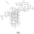
- Figure 2 schematically illustrates a detailed example implementation of the programmable current limiting circuit 10 illustrated in Figure 1 .
- the resistor network 30 is an equal value resistance ladder network having multiple resistance sections 120, or rungs.
- the sections 120 are arranged in series with each other.
- Each section 120 of the resistance ladder is connected to a distinct pin connection 42.
- the sections 120 include multiple resistors 110, with each of the resistors 110 having the same resistance value as each other of the resistors 110 within the resistor network 30, within manufacturing tolerances.
- resistor network 30 includes four sections 120, alternative examples can include any number of sections 120
- the single type of resistor 110 can be resistors 110 of equivalent values, but sourced from any number of sources. Resistors of the same resistance, within manufacturing tolerances, are referred to herein as equivalent.
- all the resistors 110 utilized to create the resistor network 30 originate from a single resistor batch. In both examples, the resistors 110 have approximately identical resistance values, within manufacturing tolerances.
- each of the pin connections 42 can be set to output either 0 volts or a positive voltage by the controller 50.
- the positive output voltage of the pin connections 42 is 5 volts.
- the programmable controller 40 By setting the voltage of any given pin connection 42 to a positive voltage, the programmable controller 40 provides a voltage to the corresponding section 120 of the resistance ladder in the resistor network 30. The voltages then promulgate through the resistor network 30 which acts as a voltage divider in conjunction with the connected voltage source 70. The output of the resistor network 30 is provided to the current threshold input 22, and sets the overcurrent threshold of the comparator 20.
- each of the current threshold input 22 and the current sense input 24 to the comparator 20 are a pair of conditioning resistors 130.
- the conditioning resistors 130 can be equivalent to the resistors 110 in the resistor network 30.
- the conditioning resistors 130 can be any other resistance, and are not equivalent.
- the above described current limiter is incorporated into a common "current limiter" circuit board.
- the common current limiter circuit board can be utilized in multiple different spacecraft, without requiring the redesign or re-qualification of the current limiter circuit.
- the resistor network 30 and the comparator 20 could be incorporated on a single circuit board and connected to an existing programmable controller within a spacecraft.
- the resolution of the variable resistor network 30 is dependent on the number of available pin connections 42 from the existing programmable controller, and the existing programmable controller can be programmed to apply any desired voltage threshold within the resistance resolution of the variable resistor network 30.
Landscapes
- Engineering & Computer Science (AREA)
- Power Engineering (AREA)
- Control Of Electric Motors In General (AREA)
- Emergency Protection Circuit Devices (AREA)
Abstract
Description
- The present disclosure relates generally to electronics for utilization in a spacecraft, and more specifically to a current limiting circuit for the same.
- Motor controller circuits frequently include current limiters that are configured to monitor a current in the motor controller and disable or reduce the current when the current exceeds an overcurrent threshold. Such circuits protect the controller, the motor, and the overall system from excessive current that can occur during operation. The specific electrical system for any given application requires a current limit tailored to that specific application, as the amount of current that can be passed through a system without damaging the system varies depending on the specifications of the system itself.
- When utilized in spacecraft, and similar applications, every element of the system including the motor controller must undergo a qualifications process to determine if it is capable of operating in conditions present outside of the Earth's atmosphere. Further, any time a component is altered within a system for spacecraft, or similar application, the entire system must be re-qualified. Requalifying a substantially similar motor controller when a current limit requirement is changed can add considerable expense to a project design.
- Disclosed is a current limiting circuit for a motor controller including: a comparator having a sensed current input, a current threshold input, and an overcurrent protection trip output, a variable resistance current threshold circuit connected to the current threshold input, and a first controller connected to the variable resistance current threshold circuit via a plurality of connections, the first controller being configured to control a voltage output of the variable resistance current threshold circuit.
- Also disclosed is a method for providing current limiting to a motor controller including: providing a sensed current to a comparator, generating a current threshold using a variable resistance resistor network, and providing the current threshold to the comparator, and comparing the sensed current to the current threshold and outputting a trip signal from the comparator when the sensed current exceeds the current threshold.
- Also disclosed is a motor controller for a spacecraft including: a current limiting circuit including a comparator having a sensed current input, a current threshold input, and an overprotection trip output, and a variable resistance resistor network having a plurality sections of equivalent resistors, an output of the variable resistance network being connected to the current threshold input, and a programmable controller having a plurality of pin connections, each of the plurality of pin connections connected to a distinct node within the variable resistance resistor network, and each of the plurality of pin connections being operable to provide one of a zero volt output and a positive voltage output.
- These and other features of the present invention can be best understood from the following specification and drawings, the following of which is a brief description.
-
-
Figure 1 schematically illustrates an example programmable current limiting circuit for a motor controller. -
Figure 2 schematically illustrates a detailed example implementation of the programmable current limiting circuit ofFigure 1 . - Current limiter circuits in motor controllers protect the controller, the motor, and the overall system from excessive current in the event of an overcurrent. Such an overcurrent can arise due to abnormal operations, start-up conditions, failures within the system, or for any similar reason. Each system requires that the particular current limiter circuit be custom tailored to meet the operational parameters and fault protection schemes for that specific system. As a result, traditional current limiter circuits are application specific.
- With regard to spacecraft, and similar applications, each circuit element is further subjected to a substantial qualifications process to ensure that the element or component is sufficiently operable in extreme conditions, such as those present outside of the Earth's atmosphere. Any change in the design of the system requires the entire system to be re-qualified.
- Current limiting circuits for spacecraft, are constructed using analog circuits and circuit elements. Existing analog current limit circuits for digital motor controller designs, however, impose a fixed current limit on the motor controller. The fixed current limit is achieved through the utilization of a fixed voltage divider providing a voltage threshold. Once the circuit is built, and installed, there is no way to alter the current limiting threshold provided by the fixed voltage divider. In certain implementations, however, it is desirable to temporarily allow the current threshold established by the current limiting circuit to be exceeded without entirely disabling current threshold protection.
- Spacecraft applications are single or low production applications, meaning that only a single system, or a very limited number of systems, requiring a given current limit circuit will ever be built. As a result of the low production numbers, and the high cost of re-qualifying each component for a new spacecraft, application specific current limit circuits are expensive to produce. However, general current limiter circuits utilizing a digital controller to compare a sensed current value against a threshold, as are known in the art, are unsuitable for some spacecraft applications.
-
Figure 1 schematically illustrates an example programmable current limitingcircuit 10, capable of generating a variable current limiting threshold. The current limiting threshold generated by the programmable current limitingcircuit 10 can be adjusted by a controller during operation without altering or replacing any of the analog current limiter circuit elements. - The programmable current limiting
circuit 10 includes acomparator 20 having acurrent threshold input 22 and acurrent sense input 24. Thecomparator 20 compares a voltage input received on thecurrent sense input 24 against a voltage input received on thecurrent threshold input 22 and outputs "high" (a positive voltage) on acomparator output 26 when thecurrent sense input 24 exceeds thecurrent threshold input 22. The output of thecomparator 20 is provided to acurrent trip circuit 60 within the motor controller containing thecurrent limit circuit 10. When the output of thecomparator 20 is high, thecurrent trip circuit 60 trips, and an overcurrent condition is prevented. Any knowncurrent trip circuit 60 can be utilized in conjunction with the system described herein. In the illustrated example, thecurrent sense input 24 is a voltage value representative of a sensed current within the motor controller, and thecurrent threshold input 22 is a voltage value representative of a current threshold. - Connected to the
current threshold input 22 of thecomparator 20 is aresistor network 30 configured to provide a voltage to thecurrent threshold input 22. Theresistor network 30 is connected to aprogrammable controller 40 viamultiple pin connections 42. Each of themultiple pin connections 42 can be set to output either zero volts or a positive voltage by theprogrammable controller 40. Each of themultiple pin connections 42 is connected to theresistor network 30 at different locations within theresistor network 30. The voltage output of theresistor network 30 is determined by which of themultiple pin connections 42 has a positive voltage at a given time. In this way, theprogrammable controller 40 can set, and alter, the current threshold for thecurrent limiter circuit 10 by altering which of thepin connections 42 are outputting a positive voltage. - In some examples the
programmable controller 40 is a Field Programmable Gate Array (FPGA) controller. In alternative examples, any other type of programmable controller qualified for utilization in spacecraft can be utilized to the same effect. In yet further examples, theprogrammable controller 40 is a control element having excess pin outputs within an existing motor controller. - By altering which
pin connections 42 output a positive voltage, the total voltage seen by thecurrent threshold input 22 is controlled by theprogrammable controller 40, and the current limit threshold can be adjusted. In this way, the controller can adjust the current limit during operations in order to temporarily override or alter the default overcurrent threshold. Utilization of theprogrammable controller 40 further allows a single circuit arrangement, such as the illustratedcircuit 10, to be utilized on a common circuit board and included within multiple distinct spacecraft, thereby reducing the costs associated with developing and qualifying a distinct current limiting circuit for each spacecraft. - While illustrated herein as including four
pin connections 42 for simplicity, it is understood thatexisting controllers 40, such as FPGA's, can include significantly moreavailable pin connections 42. Eachadditional pin connection 42 between theprogrammable controller 40 and theresistor network 30 increases the number of possible voltage thresholds and decreases a voltage difference between each possible threshold and the next possible threshold. Increasing the additional possible voltage thresholds is referred to as increasing the voltage resolution of the overvoltage threshold. - In some examples, such as the illustrated example of
Figure 1 , the variable voltage set by theprogrammable controller 40 is controlled by acontroller 50, distinct from the motor controller. In alternative examples theprogrammable controller 40 is incorporated into the motor controller, and the motor controller can control the outputs of each of thepin connections 42. Avoltage source 44 is connected to, and powers, theprogrammable controller 40. Similarly, avoltage source 70 is connected at the output of theresistor network 30 and operates in conjunction with the voltage provided by theresistor network 30 to provide the desired current threshold to thecurrent threshold input 22. In alternative examples, a single voltage source can be connected in place of the illustrated twovoltage sources - With continued reference to
Figure 1 , and with like numerals indicating like elements,Figure 2 schematically illustrates a detailed example implementation of the programmable current limitingcircuit 10 illustrated inFigure 1 . In the example ofFigure 2 , theresistor network 30 is an equal value resistance ladder network havingmultiple resistance sections 120, or rungs. Thesections 120 are arranged in series with each other. Eachsection 120 of the resistance ladder is connected to adistinct pin connection 42. Thesections 120 includemultiple resistors 110, with each of theresistors 110 having the same resistance value as each other of theresistors 110 within theresistor network 30, within manufacturing tolerances. - By utilizing approximately
identical resistors 110 within theresistor network 30, only a single type of resistor needs to undergo the spacecraft qualification process, and allresistors 110 utilized within theresistor network 30 can be sourced from a single resistor batch. The illustratedresistor network 30 includes foursections 120, alternative examples can include any number ofsections 120 In some examples, the single type ofresistor 110 can beresistors 110 of equivalent values, but sourced from any number of sources. Resistors of the same resistance, within manufacturing tolerances, are referred to herein as equivalent. In alternative examples, all theresistors 110 utilized to create theresistor network 30 originate from a single resistor batch. In both examples, theresistors 110 have approximately identical resistance values, within manufacturing tolerances. - In a practical implementation, each of the
pin connections 42 can be set to output either 0 volts or a positive voltage by thecontroller 50. In one example, the positive output voltage of thepin connections 42 is 5 volts. By setting the voltage of any givenpin connection 42 to a positive voltage, theprogrammable controller 40 provides a voltage to thecorresponding section 120 of the resistance ladder in theresistor network 30. The voltages then promulgate through theresistor network 30 which acts as a voltage divider in conjunction with the connectedvoltage source 70. The output of theresistor network 30 is provided to thecurrent threshold input 22, and sets the overcurrent threshold of thecomparator 20. - Further connecting each of the
current threshold input 22 and thecurrent sense input 24 to thecomparator 20 are a pair ofconditioning resistors 130. In some examples, theconditioning resistors 130 can be equivalent to theresistors 110 in theresistor network 30. In alternative examples, theconditioning resistors 130 can be any other resistance, and are not equivalent. - In yet a further example, the above described current limiter is incorporated into a common "current limiter" circuit board. The common current limiter circuit board can be utilized in multiple different spacecraft, without requiring the redesign or re-qualification of the current limiter circuit. By way of example, the
resistor network 30 and thecomparator 20 could be incorporated on a single circuit board and connected to an existing programmable controller within a spacecraft. The resolution of thevariable resistor network 30 is dependent on the number ofavailable pin connections 42 from the existing programmable controller, and the existing programmable controller can be programmed to apply any desired voltage threshold within the resistance resolution of thevariable resistor network 30. - It is further understood that any of the above described concepts can be used alone or in combination with any or all of the other above described concepts. Although an embodiment of this invention has been disclosed, a worker of ordinary skill in this art would recognize that certain modifications would come within the scope of this invention. For that reason, the following claims should be studied to determine the true scope of this invention.
Claims (15)
- A current limiting circuit for a motor controller comprising:a comparator (20) having a sensed current input (24), a current threshold input (22), and an overcurrent protection trip output (26);a variable resistance current threshold circuit (30) connected to the current threshold input; anda first controller (40) connected to the variable resistance current threshold circuit via a plurality of connections, the first controller being configured to control a voltage output of said variable resistance current threshold circuit.
- The current limiting circuit of claim 1, wherein the variable resistance current threshold circuit is a resistor ladder circuit.
- The current limiting circuit of claim 2, wherein the resistor ladder circuit includes a plurality of identical sections (120) connected in series, each of said sections being connected to one of said plurality of connections.
- The current limiting circuit of claim 3, wherein each of said sections includes a plurality of resistors (110).
- The current limiting circuit of claim 2, wherein each resistor in the resistor ladder circuit is equivalent.
- The current limiting circuit of claim 5, wherein said comparator further includes a first conditioning resistor (130) connecting said sensed current input to said comparator and a second conditioning resistor (130) connecting said current threshold input to said comparator, the first and second conditioning resistors being equivalent with each resistor in the resistor ladder circuit.
- The current limiting circuit of any preceding claim 1, wherein said first controller is a programmable controller.
- The current limiting circuit of any preceding claim, wherein said first controller is a control element for a spacecraft motor controller.
- The current limiting circuit of claim 8, wherein said plurality of connections are controller pin connections (42).
- A method for providing current limiting to a motor controller comprising:providing a sensed current to a comparator;generating a current threshold using a variable resistance resistor network, and providing the current threshold to the comparator; andcomparing the sensed current to the current threshold and outputting a trip signal from the comparator when the sensed current exceeds the current threshold.
- The method of claim 10, further comprising altering the current threshold in response to a controller command.
- The method of claim 11, wherein altering the current threshold comprises altering an output on at least one of a plurality of pin connections between the controller and the variable resistance resistor network.
- The method of claim 12, wherein altering the output on at least one of the plurality of pin connections comprises one of altering an output from 0 volts to a positive voltage and altering an output from a positive voltage to 0 volts, and wherein altering the output of at least one of the plurality of pin connections alters a voltage output of the resistor network.
- The method of claim 10, wherein generating the current threshold using the variable resistance resistor network comprises providing a positive voltage to at least one section of a resistor network.
- A motor controller for a spacecraft comprising:a current limiting circuit including a comparator (20) having a sensed current input (24), a current threshold input (22), and an overprotection trip output (26), and a variable resistance resistor network (30) having a plurality of sections (120) of equivalent resistors, an output of the variable resistance network being connected to the current threshold input; anda programmable controller (40) having a plurality of pin connections (42), each of said plurality of pin connections connected to a distinct node within said variable resistance resistor network, and each of said plurality of pin connections being operable to provide one of a zero volt output and a positive voltage output.
Priority Applications (1)
| Application Number | Priority Date | Filing Date | Title |
|---|---|---|---|
| EP19187343.9A EP3582393B1 (en) | 2015-06-16 | 2016-06-16 | Motor controller configured for use in a spacecraft |
Applications Claiming Priority (1)
| Application Number | Priority Date | Filing Date | Title |
|---|---|---|---|
| US14/740,412 US9647444B2 (en) | 2015-06-16 | 2015-06-16 | Variable threshold current limiting circuit |
Related Child Applications (2)
| Application Number | Title | Priority Date | Filing Date |
|---|---|---|---|
| EP19187343.9A Division EP3582393B1 (en) | 2015-06-16 | 2016-06-16 | Motor controller configured for use in a spacecraft |
| EP19187343.9A Division-Into EP3582393B1 (en) | 2015-06-16 | 2016-06-16 | Motor controller configured for use in a spacecraft |
Publications (2)
| Publication Number | Publication Date |
|---|---|
| EP3107205A1 true EP3107205A1 (en) | 2016-12-21 |
| EP3107205B1 EP3107205B1 (en) | 2019-10-02 |
Family
ID=56137153
Family Applications (2)
| Application Number | Title | Priority Date | Filing Date |
|---|---|---|---|
| EP16174730.8A Active EP3107205B1 (en) | 2015-06-16 | 2016-06-16 | Variable threshold current limiting circuit |
| EP19187343.9A Active EP3582393B1 (en) | 2015-06-16 | 2016-06-16 | Motor controller configured for use in a spacecraft |
Family Applications After (1)
| Application Number | Title | Priority Date | Filing Date |
|---|---|---|---|
| EP19187343.9A Active EP3582393B1 (en) | 2015-06-16 | 2016-06-16 | Motor controller configured for use in a spacecraft |
Country Status (2)
| Country | Link |
|---|---|
| US (1) | US9647444B2 (en) |
| EP (2) | EP3107205B1 (en) |
Families Citing this family (2)
| Publication number | Priority date | Publication date | Assignee | Title |
|---|---|---|---|---|
| US10491005B2 (en) * | 2017-02-24 | 2019-11-26 | Hall Labs Llc | Intelligent current limiting to enable chaining of AC appliances |
| KR102423301B1 (en) | 2017-12-11 | 2022-07-19 | 주식회사 엘지에너지솔루션 | Apparatus and method for preventing short |
Citations (4)
| Publication number | Priority date | Publication date | Assignee | Title |
|---|---|---|---|---|
| US6002354A (en) * | 1997-10-09 | 1999-12-14 | Kabushiki Kaisha Toshiba | Variable potential generating circuit using current-scaling adding type D/A converter circuit |
| US6170241B1 (en) * | 1996-04-26 | 2001-01-09 | Tecumseh Products Company | Microprocessor controlled motor controller with current limiting protection |
| EP1111221A2 (en) * | 1999-12-22 | 2001-06-27 | Ford Global Technologies, Inc. | System for controlling a fuel injector |
| EP2770628A2 (en) * | 2013-02-22 | 2014-08-27 | Hamilton Sundstrand Corporation | Variable link sensorless brushless direct current motor controller for space and hardened applications |
Family Cites Families (12)
| Publication number | Priority date | Publication date | Assignee | Title |
|---|---|---|---|---|
| US4839570A (en) | 1988-04-27 | 1989-06-13 | K. B. Electronics Inc. | Current limiting control circuit for d.c. motors |
| US5528721A (en) | 1992-05-04 | 1996-06-18 | John Svoboda | Direct current motor speed control apparatus |
| US5473495A (en) | 1993-12-03 | 1995-12-05 | Eaton Corporation | Combination load controller |
| US6659783B2 (en) | 2001-08-01 | 2003-12-09 | Tyco Electronics Corp | Electrical connector including variable resistance to reduce arcing |
| US20040105664A1 (en) | 2002-12-03 | 2004-06-03 | Mladen Ivankovic | Linear electric motor controller and system for providing linear speed control |
| US20030063900A1 (en) | 2001-12-13 | 2003-04-03 | Carter Group, Inc. | Linear electric motor controller and system for providing linear speed control |
| US6731082B2 (en) | 2002-03-13 | 2004-05-04 | Pelko Electric (Hk) Ltd. | DC motor constant speed PWM control |
| JP4579292B2 (en) * | 2005-12-26 | 2010-11-10 | 株式会社オートネットワーク技術研究所 | Power supply control device and threshold value changing method thereof |
| US7672107B2 (en) | 2006-10-13 | 2010-03-02 | Advanced Analogic Technologies, Inc. | Current limit control with current limit detector |
| GB201113078D0 (en) * | 2011-07-29 | 2011-09-14 | Wessex Advanced Switching Products Ltd | An aircraft interior power converter |
| CN103887760B (en) * | 2012-12-20 | 2017-11-03 | 通用电气公司 | Failsafe system and method |
| US9136782B2 (en) * | 2013-07-02 | 2015-09-15 | The Boeing Company | Motor control for stability and power supply protection |
-
2015
- 2015-06-16 US US14/740,412 patent/US9647444B2/en active Active
-
2016
- 2016-06-16 EP EP16174730.8A patent/EP3107205B1/en active Active
- 2016-06-16 EP EP19187343.9A patent/EP3582393B1/en active Active
Patent Citations (4)
| Publication number | Priority date | Publication date | Assignee | Title |
|---|---|---|---|---|
| US6170241B1 (en) * | 1996-04-26 | 2001-01-09 | Tecumseh Products Company | Microprocessor controlled motor controller with current limiting protection |
| US6002354A (en) * | 1997-10-09 | 1999-12-14 | Kabushiki Kaisha Toshiba | Variable potential generating circuit using current-scaling adding type D/A converter circuit |
| EP1111221A2 (en) * | 1999-12-22 | 2001-06-27 | Ford Global Technologies, Inc. | System for controlling a fuel injector |
| EP2770628A2 (en) * | 2013-02-22 | 2014-08-27 | Hamilton Sundstrand Corporation | Variable link sensorless brushless direct current motor controller for space and hardened applications |
Non-Patent Citations (1)
| Title |
|---|
| YUAN JUN ET AL: "A BIST scheme based on resistance match for current-mode R-2R ladder Digital-to-Analog Converter", COMPUTER RESEARCH AND DEVELOPMENT (ICCRD), 2011 3RD INTERNATIONAL CONFERENCE ON, IEEE, 11 March 2011 (2011-03-11), pages 305 - 309, XP031864302, ISBN: 978-1-61284-839-6, DOI: 10.1109/ICCRD.2011.5764201 * |
Also Published As
| Publication number | Publication date |
|---|---|
| EP3582393A1 (en) | 2019-12-18 |
| EP3582393B1 (en) | 2025-03-12 |
| US9647444B2 (en) | 2017-05-09 |
| US20160372910A1 (en) | 2016-12-22 |
| EP3107205B1 (en) | 2019-10-02 |
Similar Documents
| Publication | Publication Date | Title |
|---|---|---|
| US20050006956A1 (en) | Redundant power distribution system | |
| US11411387B2 (en) | Over/under voltage detection circuit | |
| US9806518B2 (en) | Methods of establishing and adjusting current limits for device couplers, and an electrical circuit for performing the methods | |
| US10978872B2 (en) | Power distribution system | |
| DE102016207020A1 (en) | Securing system for at least one consumer of a vehicle | |
| EP3107205B1 (en) | Variable threshold current limiting circuit | |
| US20190386486A1 (en) | Intrinsically safe circuit arrangement | |
| JP5121501B2 (en) | Overcurrent protection device and electronic device | |
| US2317030A (en) | Fuse indicating system | |
| EP3176895A2 (en) | Shared transient voltage suppressor having built-in-test capability for solid state power controllers | |
| US8552586B2 (en) | Standby power control in a multiple power supply environment | |
| DE102016000034B4 (en) | Solid state current control with semi-analog overcurrent protection | |
| EP2945241B1 (en) | Fault current limiter | |
| US3160807A (en) | Series cascades of transistors | |
| CN110571776B (en) | Surge protection circuit | |
| EP2535995B1 (en) | Overcurrent limiting for high side solenoid switch controls | |
| US9893605B2 (en) | Method and device for intrinsically safe redundant current supply of field devices | |
| WO2015174979A1 (en) | Intrinsically safe universal i/o device using programmable asic | |
| EP3740836A1 (en) | Circuit for detecting circuit defects and for preventing overvoltages in controllers | |
| DE3513179C2 (en) | Protection circuit for collectorless DC motors | |
| EP3874282B1 (en) | Overvoltage protection circuit for a control unit for a vehicle, control unit for a vehicle and method for testing an overvoltage protection circuit for a control unit for a vehicle | |
| EP3866290A1 (en) | Current limiting circuit for a control circuit for controlling a semiconductor switch system | |
| DE102018218461B4 (en) | Protective ensemble | |
| EP3346352B1 (en) | Electronic functional group | |
| US9983608B2 (en) | Output module for programmable controller |
Legal Events
| Date | Code | Title | Description |
|---|---|---|---|
| PUAI | Public reference made under article 153(3) epc to a published international application that has entered the european phase |
Free format text: ORIGINAL CODE: 0009012 |
|
| STAA | Information on the status of an ep patent application or granted ep patent |
Free format text: STATUS: THE APPLICATION HAS BEEN PUBLISHED |
|
| AK | Designated contracting states |
Kind code of ref document: A1 Designated state(s): AL AT BE BG CH CY CZ DE DK EE ES FI FR GB GR HR HU IE IS IT LI LT LU LV MC MK MT NL NO PL PT RO RS SE SI SK SM TR |
|
| AX | Request for extension of the european patent |
Extension state: BA ME |
|
| STAA | Information on the status of an ep patent application or granted ep patent |
Free format text: STATUS: REQUEST FOR EXAMINATION WAS MADE |
|
| 17P | Request for examination filed |
Effective date: 20170621 |
|
| RBV | Designated contracting states (corrected) |
Designated state(s): AL AT BE BG CH CY CZ DE DK EE ES FI FR GB GR HR HU IE IS IT LI LT LU LV MC MK MT NL NO PL PT RO RS SE SI SK SM TR |
|
| STAA | Information on the status of an ep patent application or granted ep patent |
Free format text: STATUS: EXAMINATION IS IN PROGRESS |
|
| 17Q | First examination report despatched |
Effective date: 20180801 |
|
| GRAP | Despatch of communication of intention to grant a patent |
Free format text: ORIGINAL CODE: EPIDOSNIGR1 |
|
| STAA | Information on the status of an ep patent application or granted ep patent |
Free format text: STATUS: GRANT OF PATENT IS INTENDED |
|
| RIC1 | Information provided on ipc code assigned before grant |
Ipc: H02H 9/02 20060101ALI20190313BHEP Ipc: H02H 7/08 20060101ALN20190313BHEP Ipc: H02H 3/00 20060101ALI20190313BHEP Ipc: H02P 29/032 20160101AFI20190313BHEP Ipc: H02H 3/08 20060101ALI20190313BHEP |
|
| RIC1 | Information provided on ipc code assigned before grant |
Ipc: H02H 3/00 20060101ALI20190320BHEP Ipc: H02H 9/02 20060101ALI20190320BHEP Ipc: H02H 7/08 20060101ALN20190320BHEP Ipc: H02P 29/032 20160101AFI20190320BHEP Ipc: H02H 3/08 20060101ALI20190320BHEP |
|
| INTG | Intention to grant announced |
Effective date: 20190411 |
|
| GRAS | Grant fee paid |
Free format text: ORIGINAL CODE: EPIDOSNIGR3 |
|
| GRAA | (expected) grant |
Free format text: ORIGINAL CODE: 0009210 |
|
| STAA | Information on the status of an ep patent application or granted ep patent |
Free format text: STATUS: THE PATENT HAS BEEN GRANTED |
|
| AK | Designated contracting states |
Kind code of ref document: B1 Designated state(s): AL AT BE BG CH CY CZ DE DK EE ES FI FR GB GR HR HU IE IS IT LI LT LU LV MC MK MT NL NO PL PT RO RS SE SI SK SM TR |
|
| REG | Reference to a national code |
Ref country code: GB Ref legal event code: FG4D |
|
| REG | Reference to a national code |
Ref country code: CH Ref legal event code: EP Ref country code: AT Ref legal event code: REF Ref document number: 1187330 Country of ref document: AT Kind code of ref document: T Effective date: 20191015 |
|
| REG | Reference to a national code |
Ref country code: DE Ref legal event code: R096 Ref document number: 602016021527 Country of ref document: DE |
|
| REG | Reference to a national code |
Ref country code: IE Ref legal event code: FG4D |
|
| REG | Reference to a national code |
Ref country code: NL Ref legal event code: MP Effective date: 20191002 |
|
| REG | Reference to a national code |
Ref country code: LT Ref legal event code: MG4D |
|
| REG | Reference to a national code |
Ref country code: AT Ref legal event code: MK05 Ref document number: 1187330 Country of ref document: AT Kind code of ref document: T Effective date: 20191002 |
|
| PG25 | Lapsed in a contracting state [announced via postgrant information from national office to epo] |
Ref country code: PL Free format text: LAPSE BECAUSE OF FAILURE TO SUBMIT A TRANSLATION OF THE DESCRIPTION OR TO PAY THE FEE WITHIN THE PRESCRIBED TIME-LIMIT Effective date: 20191002 Ref country code: SE Free format text: LAPSE BECAUSE OF FAILURE TO SUBMIT A TRANSLATION OF THE DESCRIPTION OR TO PAY THE FEE WITHIN THE PRESCRIBED TIME-LIMIT Effective date: 20191002 Ref country code: LV Free format text: LAPSE BECAUSE OF FAILURE TO SUBMIT A TRANSLATION OF THE DESCRIPTION OR TO PAY THE FEE WITHIN THE PRESCRIBED TIME-LIMIT Effective date: 20191002 Ref country code: GR Free format text: LAPSE BECAUSE OF FAILURE TO SUBMIT A TRANSLATION OF THE DESCRIPTION OR TO PAY THE FEE WITHIN THE PRESCRIBED TIME-LIMIT Effective date: 20200103 Ref country code: AT Free format text: LAPSE BECAUSE OF FAILURE TO SUBMIT A TRANSLATION OF THE DESCRIPTION OR TO PAY THE FEE WITHIN THE PRESCRIBED TIME-LIMIT Effective date: 20191002 Ref country code: NO Free format text: LAPSE BECAUSE OF FAILURE TO SUBMIT A TRANSLATION OF THE DESCRIPTION OR TO PAY THE FEE WITHIN THE PRESCRIBED TIME-LIMIT Effective date: 20200102 Ref country code: ES Free format text: LAPSE BECAUSE OF FAILURE TO SUBMIT A TRANSLATION OF THE DESCRIPTION OR TO PAY THE FEE WITHIN THE PRESCRIBED TIME-LIMIT Effective date: 20191002 Ref country code: NL Free format text: LAPSE BECAUSE OF FAILURE TO SUBMIT A TRANSLATION OF THE DESCRIPTION OR TO PAY THE FEE WITHIN THE PRESCRIBED TIME-LIMIT Effective date: 20191002 Ref country code: LT Free format text: LAPSE BECAUSE OF FAILURE TO SUBMIT A TRANSLATION OF THE DESCRIPTION OR TO PAY THE FEE WITHIN THE PRESCRIBED TIME-LIMIT Effective date: 20191002 Ref country code: FI Free format text: LAPSE BECAUSE OF FAILURE TO SUBMIT A TRANSLATION OF THE DESCRIPTION OR TO PAY THE FEE WITHIN THE PRESCRIBED TIME-LIMIT Effective date: 20191002 Ref country code: PT Free format text: LAPSE BECAUSE OF FAILURE TO SUBMIT A TRANSLATION OF THE DESCRIPTION OR TO PAY THE FEE WITHIN THE PRESCRIBED TIME-LIMIT Effective date: 20200203 Ref country code: BG Free format text: LAPSE BECAUSE OF FAILURE TO SUBMIT A TRANSLATION OF THE DESCRIPTION OR TO PAY THE FEE WITHIN THE PRESCRIBED TIME-LIMIT Effective date: 20200102 |
|
| PG25 | Lapsed in a contracting state [announced via postgrant information from national office to epo] |
Ref country code: IS Free format text: LAPSE BECAUSE OF FAILURE TO SUBMIT A TRANSLATION OF THE DESCRIPTION OR TO PAY THE FEE WITHIN THE PRESCRIBED TIME-LIMIT Effective date: 20200224 Ref country code: RS Free format text: LAPSE BECAUSE OF FAILURE TO SUBMIT A TRANSLATION OF THE DESCRIPTION OR TO PAY THE FEE WITHIN THE PRESCRIBED TIME-LIMIT Effective date: 20191002 Ref country code: CZ Free format text: LAPSE BECAUSE OF FAILURE TO SUBMIT A TRANSLATION OF THE DESCRIPTION OR TO PAY THE FEE WITHIN THE PRESCRIBED TIME-LIMIT Effective date: 20191002 Ref country code: HR Free format text: LAPSE BECAUSE OF FAILURE TO SUBMIT A TRANSLATION OF THE DESCRIPTION OR TO PAY THE FEE WITHIN THE PRESCRIBED TIME-LIMIT Effective date: 20191002 |
|
| PG25 | Lapsed in a contracting state [announced via postgrant information from national office to epo] |
Ref country code: AL Free format text: LAPSE BECAUSE OF FAILURE TO SUBMIT A TRANSLATION OF THE DESCRIPTION OR TO PAY THE FEE WITHIN THE PRESCRIBED TIME-LIMIT Effective date: 20191002 |
|
| REG | Reference to a national code |
Ref country code: DE Ref legal event code: R097 Ref document number: 602016021527 Country of ref document: DE |
|
| PG2D | Information on lapse in contracting state deleted |
Ref country code: IS |
|
| PG25 | Lapsed in a contracting state [announced via postgrant information from national office to epo] |
Ref country code: EE Free format text: LAPSE BECAUSE OF FAILURE TO SUBMIT A TRANSLATION OF THE DESCRIPTION OR TO PAY THE FEE WITHIN THE PRESCRIBED TIME-LIMIT Effective date: 20191002 Ref country code: DK Free format text: LAPSE BECAUSE OF FAILURE TO SUBMIT A TRANSLATION OF THE DESCRIPTION OR TO PAY THE FEE WITHIN THE PRESCRIBED TIME-LIMIT Effective date: 20191002 Ref country code: RO Free format text: LAPSE BECAUSE OF FAILURE TO SUBMIT A TRANSLATION OF THE DESCRIPTION OR TO PAY THE FEE WITHIN THE PRESCRIBED TIME-LIMIT Effective date: 20191002 Ref country code: IS Free format text: LAPSE BECAUSE OF FAILURE TO SUBMIT A TRANSLATION OF THE DESCRIPTION OR TO PAY THE FEE WITHIN THE PRESCRIBED TIME-LIMIT Effective date: 20200202 |
|
| PLBE | No opposition filed within time limit |
Free format text: ORIGINAL CODE: 0009261 |
|
| STAA | Information on the status of an ep patent application or granted ep patent |
Free format text: STATUS: NO OPPOSITION FILED WITHIN TIME LIMIT |
|
| PG25 | Lapsed in a contracting state [announced via postgrant information from national office to epo] |
Ref country code: IT Free format text: LAPSE BECAUSE OF FAILURE TO SUBMIT A TRANSLATION OF THE DESCRIPTION OR TO PAY THE FEE WITHIN THE PRESCRIBED TIME-LIMIT Effective date: 20191002 Ref country code: SK Free format text: LAPSE BECAUSE OF FAILURE TO SUBMIT A TRANSLATION OF THE DESCRIPTION OR TO PAY THE FEE WITHIN THE PRESCRIBED TIME-LIMIT Effective date: 20191002 Ref country code: SM Free format text: LAPSE BECAUSE OF FAILURE TO SUBMIT A TRANSLATION OF THE DESCRIPTION OR TO PAY THE FEE WITHIN THE PRESCRIBED TIME-LIMIT Effective date: 20191002 |
|
| 26N | No opposition filed |
Effective date: 20200703 |
|
| PG25 | Lapsed in a contracting state [announced via postgrant information from national office to epo] |
Ref country code: SI Free format text: LAPSE BECAUSE OF FAILURE TO SUBMIT A TRANSLATION OF THE DESCRIPTION OR TO PAY THE FEE WITHIN THE PRESCRIBED TIME-LIMIT Effective date: 20191002 |
|
| PG25 | Lapsed in a contracting state [announced via postgrant information from national office to epo] |
Ref country code: MC Free format text: LAPSE BECAUSE OF FAILURE TO SUBMIT A TRANSLATION OF THE DESCRIPTION OR TO PAY THE FEE WITHIN THE PRESCRIBED TIME-LIMIT Effective date: 20191002 |
|
| REG | Reference to a national code |
Ref country code: CH Ref legal event code: PL |
|
| PG25 | Lapsed in a contracting state [announced via postgrant information from national office to epo] |
Ref country code: LU Free format text: LAPSE BECAUSE OF NON-PAYMENT OF DUE FEES Effective date: 20200616 |
|
| REG | Reference to a national code |
Ref country code: BE Ref legal event code: MM Effective date: 20200630 |
|
| PG25 | Lapsed in a contracting state [announced via postgrant information from national office to epo] |
Ref country code: IE Free format text: LAPSE BECAUSE OF NON-PAYMENT OF DUE FEES Effective date: 20200616 Ref country code: LI Free format text: LAPSE BECAUSE OF NON-PAYMENT OF DUE FEES Effective date: 20200630 Ref country code: CH Free format text: LAPSE BECAUSE OF NON-PAYMENT OF DUE FEES Effective date: 20200630 |
|
| PG25 | Lapsed in a contracting state [announced via postgrant information from national office to epo] |
Ref country code: BE Free format text: LAPSE BECAUSE OF NON-PAYMENT OF DUE FEES Effective date: 20200630 |
|
| PG25 | Lapsed in a contracting state [announced via postgrant information from national office to epo] |
Ref country code: TR Free format text: LAPSE BECAUSE OF FAILURE TO SUBMIT A TRANSLATION OF THE DESCRIPTION OR TO PAY THE FEE WITHIN THE PRESCRIBED TIME-LIMIT Effective date: 20191002 Ref country code: MT Free format text: LAPSE BECAUSE OF FAILURE TO SUBMIT A TRANSLATION OF THE DESCRIPTION OR TO PAY THE FEE WITHIN THE PRESCRIBED TIME-LIMIT Effective date: 20191002 Ref country code: CY Free format text: LAPSE BECAUSE OF FAILURE TO SUBMIT A TRANSLATION OF THE DESCRIPTION OR TO PAY THE FEE WITHIN THE PRESCRIBED TIME-LIMIT Effective date: 20191002 |
|
| PG25 | Lapsed in a contracting state [announced via postgrant information from national office to epo] |
Ref country code: MK Free format text: LAPSE BECAUSE OF FAILURE TO SUBMIT A TRANSLATION OF THE DESCRIPTION OR TO PAY THE FEE WITHIN THE PRESCRIBED TIME-LIMIT Effective date: 20191002 |
|
| P01 | Opt-out of the competence of the unified patent court (upc) registered |
Effective date: 20230522 |
|
| PGFP | Annual fee paid to national office [announced via postgrant information from national office to epo] |
Ref country code: DE Payment date: 20250520 Year of fee payment: 10 |
|
| PGFP | Annual fee paid to national office [announced via postgrant information from national office to epo] |
Ref country code: GB Payment date: 20250520 Year of fee payment: 10 |
|
| PGFP | Annual fee paid to national office [announced via postgrant information from national office to epo] |
Ref country code: FR Payment date: 20250520 Year of fee payment: 10 |