EP3107190A1 - Rotating electrical machine - Google Patents
Rotating electrical machine Download PDFInfo
- Publication number
- EP3107190A1 EP3107190A1 EP15748473.4A EP15748473A EP3107190A1 EP 3107190 A1 EP3107190 A1 EP 3107190A1 EP 15748473 A EP15748473 A EP 15748473A EP 3107190 A1 EP3107190 A1 EP 3107190A1
- Authority
- EP
- European Patent Office
- Prior art keywords
- stator
- stator core
- inner diameter
- housing
- expansion region
- Prior art date
- Legal status (The legal status is an assumption and is not a legal conclusion. Google has not performed a legal analysis and makes no representation as to the accuracy of the status listed.)
- Withdrawn
Links
- 229910000831 Steel Inorganic materials 0.000 claims abstract description 27
- 239000010959 steel Substances 0.000 claims abstract description 27
- 230000002093 peripheral effect Effects 0.000 claims abstract description 20
- 229910000576 Laminated steel Inorganic materials 0.000 claims abstract description 14
- 238000010030 laminating Methods 0.000 abstract description 2
- 230000004308 accommodation Effects 0.000 description 9
- 238000009413 insulation Methods 0.000 description 4
- XAGFODPZIPBFFR-UHFFFAOYSA-N aluminium Chemical compound [Al] XAGFODPZIPBFFR-UHFFFAOYSA-N 0.000 description 3
- 229910052782 aluminium Inorganic materials 0.000 description 3
- 239000000470 constituent Substances 0.000 description 2
- 238000004519 manufacturing process Methods 0.000 description 2
- 238000000034 method Methods 0.000 description 2
- 238000011144 upstream manufacturing Methods 0.000 description 2
- 230000008602 contraction Effects 0.000 description 1
- 230000007423 decrease Effects 0.000 description 1
- 230000000694 effects Effects 0.000 description 1
- 238000010292 electrical insulation Methods 0.000 description 1
Images


Classifications
-
- H—ELECTRICITY
- H02—GENERATION; CONVERSION OR DISTRIBUTION OF ELECTRIC POWER
- H02K—DYNAMO-ELECTRIC MACHINES
- H02K1/00—Details of the magnetic circuit
- H02K1/06—Details of the magnetic circuit characterised by the shape, form or construction
- H02K1/12—Stationary parts of the magnetic circuit
- H02K1/18—Means for mounting or fastening magnetic stationary parts on to, or to, the stator structures
- H02K1/185—Means for mounting or fastening magnetic stationary parts on to, or to, the stator structures to outer stators
-
- F—MECHANICAL ENGINEERING; LIGHTING; HEATING; WEAPONS; BLASTING
- F02—COMBUSTION ENGINES; HOT-GAS OR COMBUSTION-PRODUCT ENGINE PLANTS
- F02B—INTERNAL-COMBUSTION PISTON ENGINES; COMBUSTION ENGINES IN GENERAL
- F02B39/00—Component parts, details, or accessories relating to, driven charging or scavenging pumps, not provided for in groups F02B33/00 - F02B37/00
- F02B39/02—Drives of pumps; Varying pump drive gear ratio
- F02B39/08—Non-mechanical drives, e.g. fluid drives having variable gear ratio
- F02B39/10—Non-mechanical drives, e.g. fluid drives having variable gear ratio electric
-
- H—ELECTRICITY
- H02—GENERATION; CONVERSION OR DISTRIBUTION OF ELECTRIC POWER
- H02K—DYNAMO-ELECTRIC MACHINES
- H02K5/00—Casings; Enclosures; Supports
- H02K5/04—Casings or enclosures characterised by the shape, form or construction thereof
- H02K5/18—Casings or enclosures characterised by the shape, form or construction thereof with ribs or fins for improving heat transfer
-
- F—MECHANICAL ENGINEERING; LIGHTING; HEATING; WEAPONS; BLASTING
- F02—COMBUSTION ENGINES; HOT-GAS OR COMBUSTION-PRODUCT ENGINE PLANTS
- F02B—INTERNAL-COMBUSTION PISTON ENGINES; COMBUSTION ENGINES IN GENERAL
- F02B37/00—Engines characterised by provision of pumps driven at least for part of the time by exhaust
- F02B37/04—Engines with exhaust drive and other drive of pumps, e.g. with exhaust-driven pump and mechanically-driven second pump
-
- H—ELECTRICITY
- H02—GENERATION; CONVERSION OR DISTRIBUTION OF ELECTRIC POWER
- H02K—DYNAMO-ELECTRIC MACHINES
- H02K2213/00—Specific aspects, not otherwise provided for and not covered by codes H02K2201/00 - H02K2211/00
- H02K2213/03—Machines characterised by numerical values, ranges, mathematical expressions or similar information
Definitions
- This invention relates to a rotating electric machine.
- An electric turbocharger installed in a vehicle includes a rotating electric machine, or in other words an electric motor, used to drive a compressor.
- an electric motor 112 of a conventional turbocharger 110 includes a rotor 113 and a stator 114 that are disposed opposite each other in the interior of a housing 117.
- the stator 114 includes a stator core 114a and stator coils 114b provided on respective ends of the stator core 114a.
- the stator core 114a of the stator 114 is formed from laminated steel plates obtained by overlapping a plurality of thin steel plates S. Further, an insulation distance A is set between the stator core 114a and the stator coil 114b.
- stator core 114a of the stator 114 is fixed to the housing 117 by shrink fitting.
- shrink fitting is a method of fixing the stator 114 in position by thermally expanding the housing 117 so that an inner diameter thereof expands, fitting the stator core 114a of the stator 114, which is at normal temperature, in a predetermined position, and then returning the temperature of the housing 117 to a normal temperature so that the inner diameter thereof contracts.
- the stator core 114a of the shrink-fitted stator 114 receives a fastening force F' from the housing 117.
- the steel plate S on the end of the laminated steel plates forming the stator core 114a of the stator 114 may separate from the adjacent steel plate S and deform so as to curl over, as shown in Fig. 6B .
- the electric turbocharger 110 is installed specifically in a vehicle, and therefore, to achieve a reduction in weight, the housing 117 is formed from aluminum.
- the fastening force F' from the housing 117 increases at low temperatures, making it more likely for the steel plate S to deform.
- the electric motor 112 used in the electric turbocharger 110 rotates at an extremely high speed, and therefore, to reduce eddy current loss, the steel plates used as the laminated steel plates are thinner than usual. As a result, the degree to which the steel plate curls over or otherwise deforms is particularly striking.
- a distance B between the curled-over steel plate S and the stator coil 114b becomes smaller than the originally set insulation distance A between the stator core 114a and the stator coil 114b of the stator 114.
- the distance B between the steel plate S and the stator coil 114b is smaller than the set insulation distance A, electrical insulation may break down upon application of a voltage, and as a result, short circuiting may occur.
- Patent Document 1 Japanese Patent Application Publication No. 2011-172335
- the laminated steel plates contact the housing in locations other than the respective end portions of the core, and the steel plates in these locations may still be deformed by the fastening force from the housing.
- a steel plate located close to the stator coil curls over in a location other than the end portions of the core, it is similarly difficult to secure an accurate insulation distance between the steel plates and the stator coil.
- a new stator core mold must be prepared to reduce the diameter of only the respective end portions of the stator core, leading to an increase in manufacturing costs.
- This invention has been designed to solve the problems described above, and an object thereof is to provide a rotating electric machine in which laminated steel plates forming a stator core can be prevented from deforming by means of a simple structure.
- a rotating electric machine includes: a casing, a rotary shaft supported rotatably by the casing, a rotor attached fixedly to the rotary shaft and housed in the interior of the casing, and a stator fixed to the casing and provided opposite the rotor on a radially outer side of the rotor, wherein the stator includes a stator core formed from a plurality of steel plates laminated in an axial direction of the rotary shaft, the stator core is fixedly attached to a stator attachment surface provided on an inner peripheral surface of the casing, an inner diameter expansion region formed so as not to contact the stator core is provided adjacent to the stator attachment surface on the inner peripheral surface of the casing in a position opposing an end part of the stator core, the inner diameter expansion region is adjacent to the stator attachment surface, and a diameter of the inner diameter expansion region is larger than a diameter of the stator attachment surface.
- the end part of the stator core does not contact the casing, and as a result, no force acts on the end part of the stator core even when the casing contracts.
- the inner diameter expansion region of the rotating electric machine according to this invention may include an inclined surface that inclines in the axial direction of the rotary shaft.
- a length of the inner diameter expansion region in the axial direction of the rotary shaft may equal or exceed a length of ten of the laminated steel plates.
- the inner diameter expansion region may be provided respectively in positions opposing end parts forming respective ends of the stator core.
- the length of the inner diameter expansion region in the axial direction of the rotary shaft may be increased as an outer diameter of the stator core increases.
- the laminated steel plates forming the stator core can be prevented from deforming by means of a simple structure.
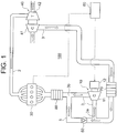
- Fig. 1 shows a supercharging system 100 including an electric turbocharger 10 that includes a rotating electric machine, or in other words an electric motor 12, according to this embodiment.
- an exhaust passage 2 through which exhaust gas flows and an intake passage 3 through which intake air flows are connected to an engine 30 of a vehicle.
- a turbine portion 42 of an exhaust gas turbocharger 40 is provided in the exhaust passage 2.
- a compressor portion 41 of the exhaust gas turbocharger 40 is provided in the intake passage 3.
- the compressor portion 41 and the turbine portion 42 are connected integrally so that when the turbine portion 42 is driven to rotate by pressure from the exhaust gas, the compressor portion 41 also rotates.
- the exhaust gas turbocharger 40 is driven by energy from the exhaust gas of the engine 30 so as to compress the intake air. Further, a first intercooler 70, an electric turbocharger 10, and a second intercooler 80 are provided in the intake passage 3 downstream of the exhaust gas turbocharger 40 in that order.
- the intake passage 3 together with the exhaust gas turbocharger 40 and the electric turbocharger 10 provided in the intake passage 3 constitute the supercharging system 100 for compressing the intake air that flows into the engine 30.
- the electric turbocharger 10 includes a compressor 11 provided in the intake passage 3, and the electric motor 12, which is connected to the compressor 11. In other words, the electric turbocharger 10 is driven by the electric motor 12 so as to compress the intake air.
- an ECU 60 is electrically connected to both the engine 30 and the electric turbocharger 10.
- a bypass passage 5 that bypasses the electric turbocharger 10 is connected to the intake passage 3.
- one end of the bypass passage 5 is connected to a first bifurcation point 3a provided downstream of the first intercooler 70 and upstream of the electric turbocharger 10.
- another end of the bypass passage 5 is connected to a second bifurcation point 3b provided downstream of the electric turbocharger 10 and upstream of the second intercooler 80.
- a check valve 50 is provided in the bypass passage 5.
- the electric motor 12 of the electric turbocharger 10 includes an aluminum housing 17.
- a plurality of heat dissipating fins 18 are formed on an outer peripheral surface of the housing 17.
- a substantially columnar accommodation space 15 is formed in the interior of the housing 17.
- a rotary shaft 16 extends through the accommodation space 15 along a central axis of the housing 17.
- the rotary shaft 16 is supported rotatably by the housing 17 via bearings 19a, 19b.
- axial directions of the rotary shaft 16 are defined such that a rightward direction on the paper surface of Fig. 2 is set as an X direction and a leftward direction on the paper surface of Fig. 2 is set as an X' direction.
- An X' direction end of the rotary shaft 16 extends so as to project to the exterior of the housing 17.
- the compressor 11 is attached fixedly to the part of the rotary shaft 16 that projects to the exterior of the housing 17 so as to be capable of rotating integrally therewith.
- the housing 17 constitutes a casing.
- a rotor 13 is attached fixedly to the rotary shaft 16.
- the rotor 13 is housed in the interior of the housing 17.
- a stator bearing portion 37 is formed as a strip-form projecting part on an inner peripheral surface of the housing 17 facing the accommodation space 15.
- the stator bearing portion 37 includes a stator attachment surface 37a formed as a cylindrical curved surface.
- an inclined surface 37c is formed adjacent to the stator attachment surface 37a on an X direction end portion of the stator bearing portion 37 so as to widen outwardly in a radial direction toward the X direction side.
- the inclined surface 37c inclines relative to the axial direction of the rotary shaft 16. As shown in Fig.
- a boundary between the stator attachment surface 37a and the inclined surface 37c constitutes an X' direction end portion 37e of the inclined surface 37c.
- 37f denotes an X direction end portion of the inclined surface 37c.
- a flange 37d that projects inwardly in the radial direction is formed adjacent to the stator attachment surface 37a on an X' direction end portion of the stator bearing portion 37.
- a substantially cylindrical stator core 14a is fixed by shrink fitting to the stator attachment surface 37a of the stator bearing portion 37.
- the stator core 14a is formed by laminating a plurality of steel plates St having uniform thicknesses t in the axial direction of the rotary shaft (see Fig. 4 ).
- stator core 14a forms a cylindrical curved surface. Furthermore, an X' direction end portion of the stator core 14a contacts the flange 37d such that the stator core 14a is disposed opposite the rotor 13 on an outer side of the rotor 13. Moreover, stator coils 14b are attached to respective ends of the stator core 14a. The stator core 14a and the stator coils 14b together constitute a stator 14.
- the flange 37d functions as a stopper that delimits the position of the stator 14 when the stator 14 is fitted into the interior of the housing 17 from the X direction side. Moreover, the flange 37d contacts the X' direction end portion steel plate St of the stator core 14a so that the steel plate St on the X' direction end portion of the stator core 14a is prevented from curling over by the flange 37d.
- a line corresponding to a position in which an X direction end surface of the stator core 14a extends outwardly in the radial direction is set as an expansion portion boundary line 37g.
- a region on the inner peripheral surface of the housing 17 between the end portion 37e of the inclined surface 37c and the expansion portion boundary line 37g constitutes an inner diameter expansion region 37b.
- the length L3 of the inner diameter expansion region 37b is greater than a length 10t of ten of the laminated steel plates St.
- a part of the stator core 14a constituted by the ten steel plates laminated from the X direction end portion of the stator core 14a is set as an end part 14c of the stator core 14a.
- the inner diameter expansion region 37b on the inner peripheral surface of the housing 17 is formed in a position opposing the end part 14c of the stator core 14a.
- the length L2 of the stator attachment surface 37a is set so that the stator 14 can remain fixed to the housing 17 over the entire operating temperature range of the electric turbocharger 10.
- the outer diameter of the stator core 14a is set at ⁇ D1.
- ⁇ D1 is set at approximately 60 mm.
- the diameter of the stator attachment surface 37a of the stator bearing portion 37 is set to be substantially identical to the outer diameter of the stator core 14a. In other words, the diameter of the stator attachment surface 37a is also set at ⁇ D1.
- parts of an inner wall of the housing 17 other than the stator bearing portion 37 are formed as cylindrical curved surfaces having an inner diameter of ⁇ D2.
- the diameter ⁇ D2 is larger than the diameter ⁇ D1.
- the inner diameter of the housing 17 expands in the X direction from ⁇ D1 to ⁇ D2, and therefore the diameter of the inner diameter expansion region 37b is larger than the diameter of the stator attachment surface 37a.
- the diameter of the inner diameter expansion region 37b is simultaneously larger than the diameter of the stator core 14a, and therefore the inner diameter expansion region 37b is formed so as not to contact the stator core 14a.
- the turbine portion 42 of the exhaust gas turbocharger 40 When the engine 30 rotates at or above a predetermined speed, the turbine portion 42 of the exhaust gas turbocharger 40 is driven to rotate by the pressure of the exhaust gas flowing into the exhaust passage 2. Accordingly, the compressor portion 41 of the exhaust gas turbocharger 40 is driven, and as a result, the intake air flowing through the intake passage 3 is compressed by the compressor portion 41. Next, the compressed intake air is cooled by the first intercooler 70.
- the ECU 60 reads the rotation speed of the engine 30. The ECU 60 determines whether or not the engine 30 is rotating at a high speed, and when the engine 30 is rotating at a high speed that equals or exceeds the predetermined speed, the ECU 60 maintains the electric motor 12 of the electric turbocharger 10 in a stopped condition.
- the turbine portion 42 of the exhaust gas turbocharger 40 cannot obtain sufficient energy from the exhaust gas.
- the compressor portion 41 of the exhaust gas turbocharger 40 cannot increase the supercharging pressure of the intake air sufficiently.
- the ECU 60 determines whether or not the engine 30 is rotating at or above the predetermined speed, and when the engine 30 is rotating below the predetermined speed, the ECU 60 drives the electric motor 12 of the electric turbocharger 10 to rotate.
- the turbine portion 42 of the exhaust gas turbocharger 40 cannot obtain sufficient energy from the exhaust gas immediately after startup, and therefore the electric turbocharger 40 may be driven.
- a three-phase alternating current is passed through the stator coils 14b from a storage battery (not shown) via an inverter (not shown) such that a rotating magnetic field is generated between the stator 14 and the rotor 13, whereby the rotary shaft 16 rotates together with the compressor 11 (see Fig. 2 ).
- the intake air in the intake passage 3 which has passed through the compressor portion 41 of the exhaust gas turbocharger 40 without being sufficiently compressed, passes through the first intercooler 70 and the first bifurcation point 3a so as to be compressed by the compressor 11 of the electric turbocharger 10.
- the check valve 50 provided in the bypass passage 5 is in a closed condition, and therefore the intake air does not flow into the bypass passage 5.
- the intake air compressed by the electric turbocharger 10 passes through the second bifurcation point 3b so as to be cooled by the second intercooler 80, and then flows into the engine 30.
- the inner diameter expansion region 37b provided on the inner peripheral surface of the housing 17 in a position opposing the end part 14c of the stator core 14a has a larger diameter than the stator attachment surface 37a, and therefore does not contact the stator core 14a. Accordingly, even when a fastening force F generated upon contraction of the housing 17 following the shrink fitting is received by the stator core 14a, the fastening force F does not act directly on the steel plates St forming the end part 14c of the stator core 14a. There is therefore no need to modify the shape of the stator core 14a, and as a result, deformation of the steel plates St forming the end part 14c of the stator core 14a can be prevented by means of a simple structure.
- shrink fitting is used as the method for fixing the stator core 14a to the inner peripheral surface of the housing 17, components such as fixing bolts are not required, and therefore a corresponding reduction in manufacturing cost can be achieved.
- holes and the like for passing bolts need not be provided in the housing 17, and therefore the electric turbocharger 10 itself can be reduced in size.
- the inner diameter expansion region 37b includes the inclined surface 37c that inclines relative to the axial direction of the rotary shaft 16.
- the inclined surface 37c contacts the end portion of the stator core 14a, and as a result, the stator core 14a is guided into the stator attachment surface 37a more smoothly.
- the length L3 the inner diameter expansion region equals or exceeds the length 10t of ten of the laminated steel plates St, and therefore deformation of the steel plate St on the end portion of the stator core 14a can be prevented more reliably.
- Fig. 5 shows a configuration of an electric turbocharger 20 having a rotating electric machine, or in other words an electric motor 22, according to this embodiment of the invention.
- the housing 17 of the electric turbocharger 10 according to the first embodiment is replaced with a housing 27 that includes a stator bearing portion 47 formed with two inclined surfaces 47c, 47h.
- the electric motor 22 of the electric turbocharger 20 includes the aluminum housing 27.
- a plurality of heat dissipating fins 28 are formed on an outer peripheral surface of the housing 27.
- the substantially columnar accommodation space 15 is formed in the interior of the housing 27 in a similar manner to the interior of the housing 17 of the electric turbocharger 10 according to the first embodiment.
- the stator bearing portion 47 is formed as a strip-form projecting part on an inner peripheral surface of the housing 27 facing the accommodation space 15.
- the stator bearing portion 47 includes a stator attachment surface 47a formed as a cylindrical curved surface.
- the inclined surface 47c is formed adjacent to the stator attachment surface 47a on an X direction end portion of the stator bearing portion 47 so as to widen outwardly in the radial direction toward the X direction side.
- a boundary between the stator attachment surface 47a and the inclined surface 47c constitutes an X' direction end portion 47e of the inclined surface 47c.
- 47f denotes an X direction end portion of the inclined surface 47c.
- the inclined surface 47h is formed adjacent to the stator attachment surface 47a on an X' direction end portion of the stator bearing portion 47 so as to widen outwardly in the radial direction toward the X' direction side.
- a boundary between the stator attachment surface 47a and the inclined surface 47h constitutes an X direction end portion 47k of the inclined surface 47h. Furthermore, 47j denotes an X' direction end portion of the inclined surface 47c. Further, the stator core 14a is fixed by shrink fitting to the stator attachment surface 47a of the stator bearing portion 47.
- a line corresponding to the position in which the X direction end surface of the stator core 14a extends outwardly in the radial direction is set as a first expansion portion boundary line 47g.
- a region on the inner peripheral surface of the housing 27 between the end portion 47e of the inclined surface 47c and the first expansion portion boundary line 47g constitutes a first inner diameter expansion region 47b.
- a line corresponding to a position in which an X' direction end surface of the stator core 14a extends outwardly in the radial direction is set as a second expansion portion boundary line 47m.
- a region on the inner peripheral surface of the housing 27 between the end portion 47k of the inclined surface 47h and the second expansion portion boundary line 47m constitutes a second inner diameter expansion region 47i.
- the length of the stator attachment surface 47a in the axial direction of the rotary shaft 16 is set at L4. Further, the lengths of the first inner diameter expansion region 47b and the second inner diameter expansion region 47i in the axial direction of the rotary shaft 16 are set respectively at L5. The length L5 of the first inner diameter expansion region 47b and the second inner diameter expansion region 47i is greater than the length 10t of ten of the laminated steel plates St. Furthermore, here, similarly to the end part 14c of the stator core 14a, a part of the stator core 14a constituted by the ten steel plates laminated from the X' direction end portion of the stator core 14a is set as an end part 14d. In other words, the first inner diameter expansion region 47b and second inner diameter expansion region 47i on the inner peripheral surface of the housing 17 are formed in positions opposing the end parts 14c, 14d formed at the respective ends of the stator core 14a.
- the length L4 of the stator attachment surface 47a is set so that the stator 14 can remain fixed to the housing 27 over the entire operating temperature range of the electric turbocharger 20.
- the diameter of the stator attachment surface 47a is set at ⁇ D1, i.e. a diameter identical to the diameter of the stator attachment surface 37a according to the first embodiment.
- ⁇ D1 i.e. a diameter identical to the diameter of the stator attachment surface 37a according to the first embodiment.
- parts of an inner wall of the housing 27 other than the stator bearing portion 37, or in other words a part that extends in the X direction from the end portion 47f of the inclined surface 47c and a part that extends in the X' direction from the end portion 47j of the inclined surface 47h, are formed as cylindrical curved surfaces having an inner diameter of ⁇ D3.
- the diameter ⁇ D3 is larger than the diameter ⁇ D1.
- the inner diameter of the housing 27 expands in the X direction in the first inner diameter expansion region 47b and expands in the X' direction in the second inner diameter expansion region 47i.
- the diameters of the first inner diameter expansion region 47b and the second inner diameter expansion region 47i are respectively larger than the diameter of the stator attachment surface 47a.
- the respective diameters of the first inner diameter expansion region 47b and the second inner diameter expansion region 47i are simultaneously larger than the diameter of the stator core 14a, and therefore the first inner diameter expansion region 47b and the second inner diameter expansion region 47i are formed so as not to contact the stator core 14a.
- the first inner diameter expansion region 47b and the second inner diameter expansion region 47i are provided respectively in positions opposing the end parts 14c, 14d forming the respective ends of the stator core 14a. Therefore, deformation of the steel plates St on the end parts 14c, 14d forming the respective ends of the stator core 14a can be prevented.
- the length L3 of the inner diameter expansion region 37b in the axial direction of the rotary shaft 16 may be varied in accordance with the outer diameter ⁇ D1 of the stator core 14a.
- the length L3 of the inner diameter expansion region 37b may be increased as the outer diameter of the stator core 14a increases, and reduced as the outer diameter of the stator core 14a decreases. More specifically, when the outer diameter ⁇ D1 of the stator core 14a is approximately 60 mm, the length L3 of the inner diameter expansion region 37b is set to be approximately equal to the length 10t of ten of the laminated steel plates St, but when ⁇ D1 is increased, the length L3 of the inner diameter expansion region 37b is increased in accordance with ⁇ D1. In so doing, the steel plates St can be prevented from deforming so as to curl over while securing the fastening force F from the housing 17. This applies likewise to the length L5 of the first inner diameter expansion regions 47b and 47i according to the second embodiment.
Landscapes
- Engineering & Computer Science (AREA)
- Power Engineering (AREA)
- Physics & Mathematics (AREA)
- Thermal Sciences (AREA)
- Chemical & Material Sciences (AREA)
- Combustion & Propulsion (AREA)
- Mechanical Engineering (AREA)
- General Engineering & Computer Science (AREA)
- Iron Core Of Rotating Electric Machines (AREA)
- Supercharger (AREA)
Abstract
Description
- This invention relates to a rotating electric machine.
- An electric turbocharger installed in a vehicle includes a rotating electric machine, or in other words an electric motor, used to drive a compressor. As shown in
Fig. 6A , anelectric motor 112 of aconventional turbocharger 110 includes arotor 113 and astator 114 that are disposed opposite each other in the interior of ahousing 117. Thestator 114 includes astator core 114a andstator coils 114b provided on respective ends of thestator core 114a. As shown inFig. 6B , thestator core 114a of thestator 114 is formed from laminated steel plates obtained by overlapping a plurality of thin steel plates S. Further, an insulation distance A is set between thestator core 114a and thestator coil 114b. Moreover, thestator core 114a of thestator 114 is fixed to thehousing 117 by shrink fitting. Note that "shrink fitting" is a method of fixing thestator 114 in position by thermally expanding thehousing 117 so that an inner diameter thereof expands, fitting thestator core 114a of thestator 114, which is at normal temperature, in a predetermined position, and then returning the temperature of thehousing 117 to a normal temperature so that the inner diameter thereof contracts. - Here, when the inner diameter of the
housing 117 contracts, thestator core 114a of the shrink-fittedstator 114 receives a fastening force F' from thehousing 117. As a result, the steel plate S on the end of the laminated steel plates forming thestator core 114a of thestator 114 may separate from the adjacent steel plate S and deform so as to curl over, as shown inFig. 6B . Theelectric turbocharger 110 is installed specifically in a vehicle, and therefore, to achieve a reduction in weight, thehousing 117 is formed from aluminum. Moreover, due to a wide operating temperature range, the fastening force F' from thehousing 117 increases at low temperatures, making it more likely for the steel plate S to deform. Furthermore, theelectric motor 112 used in theelectric turbocharger 110 rotates at an extremely high speed, and therefore, to reduce eddy current loss, the steel plates used as the laminated steel plates are thinner than usual. As a result, the degree to which the steel plate curls over or otherwise deforms is particularly striking. - When the steel plate S deforms in this manner, a distance B between the curled-over steel plate S and the
stator coil 114b becomes smaller than the originally set insulation distance A between thestator core 114a and thestator coil 114b of thestator 114. When the distance B between the steel plate S and thestator coil 114b is smaller than the set insulation distance A, electrical insulation may break down upon application of a voltage, and as a result, short circuiting may occur. - To solve this problem, in an electric motor described in
Patent Document 1, end portion steel plates are prevented from deforming so as to curl over by reducing the diameter of the laminated steel plates forming the stator core at the respective end parts only, as shown inFigs. 3 to 5 ofPatent Document 1. CITATION LIST - Patent Document 1: Japanese Patent Application Publication No.
2011-172335 - In the electric motor described in
Patent Document 1, however, the laminated steel plates contact the housing in locations other than the respective end portions of the core, and the steel plates in these locations may still be deformed by the fastening force from the housing. When a steel plate located close to the stator coil curls over in a location other than the end portions of the core, it is similarly difficult to secure an accurate insulation distance between the steel plates and the stator coil. Moreover, in the electric motor ofPatent Document 1, a new stator core mold must be prepared to reduce the diameter of only the respective end portions of the stator core, leading to an increase in manufacturing costs. - This invention has been designed to solve the problems described above, and an object thereof is to provide a rotating electric machine in which laminated steel plates forming a stator core can be prevented from deforming by means of a simple structure.
- To solve the problems described above, a rotating electric machine according to this invention includes: a casing, a rotary shaft supported rotatably by the casing, a rotor attached fixedly to the rotary shaft and housed in the interior of the casing, and a stator fixed to the casing and provided opposite the rotor on a radially outer side of the rotor, wherein the stator includes a stator core formed from a plurality of steel plates laminated in an axial direction of the rotary shaft, the stator core is fixedly attached to a stator attachment surface provided on an inner peripheral surface of the casing, an inner diameter expansion region formed so as not to contact the stator core is provided adjacent to the stator attachment surface on the inner peripheral surface of the casing in a position opposing an end part of the stator core, the inner diameter expansion region is adjacent to the stator attachment surface, and a diameter of the inner diameter expansion region is larger than a diameter of the stator attachment surface.
- Thus, the end part of the stator core does not contact the casing, and as a result, no force acts on the end part of the stator core even when the casing contracts.
- Further, the inner diameter expansion region of the rotating electric machine according to this invention may include an inclined surface that inclines in the axial direction of the rotary shaft.
- Furthermore, a length of the inner diameter expansion region in the axial direction of the rotary shaft may equal or exceed a length of ten of the laminated steel plates.
- Moreover, the inner diameter expansion region may be provided respectively in positions opposing end parts forming respective ends of the stator core.
- Furthermore, the length of the inner diameter expansion region in the axial direction of the rotary shaft may be increased as an outer diameter of the stator core increases.
- With the rotating electric machine according to this invention, the laminated steel plates forming the stator core can be prevented from deforming by means of a simple structure.
-
- [
Fig. 1] Fig. 1 is a schematic view showing a supercharging system employing an electric turbocharger that includes a rotating electric machine according to a first embodiment of this invention. - [
Fig. 2] Fig. 2 is a schematic sectional view of the rotating electric machine according to the first embodiment of this invention. - [
Fig. 3] Fig. 3 is an enlarged view showing the vicinity of a fixing location between a housing and a stator core in the rotating electric machine shown inFig. 2 . - [
Fig. 4] Fig. 4 is an enlarged view showing the vicinity of an end portion of the stator core in the rotating electric machine shown inFig. 2 . - [
Fig. 5] Fig. 5 is an enlarged schematic view showing the vicinity of a fixing location between a housing and a stator core in a rotating electric machine according to a second embodiment of this invention. - [
Fig. 6A] Fig. 6A is a schematic sectional view showing a rotating electric machine according to a conventional example. - [
Fig. 6B] Fig. 6B is an enlarged view showing the condition of a stator core when a fastening force from a housing acts thereon in the rotating electric machine shown inFig. 6A . - Embodiments of this invention will be described below on the basis of the attached drawings.
-
Fig. 1 shows asupercharging system 100 including anelectric turbocharger 10 that includes a rotating electric machine, or in other words anelectric motor 12, according to this embodiment. As shown inFig. 1 , anexhaust passage 2 through which exhaust gas flows and an intake passage 3 through which intake air flows are connected to anengine 30 of a vehicle. Aturbine portion 42 of anexhaust gas turbocharger 40 is provided in theexhaust passage 2. Meanwhile, acompressor portion 41 of theexhaust gas turbocharger 40 is provided in the intake passage 3. In theexhaust gas turbocharger 40, thecompressor portion 41 and theturbine portion 42 are connected integrally so that when theturbine portion 42 is driven to rotate by pressure from the exhaust gas, thecompressor portion 41 also rotates. In other words, theexhaust gas turbocharger 40 is driven by energy from the exhaust gas of theengine 30 so as to compress the intake air. Further, afirst intercooler 70, anelectric turbocharger 10, and asecond intercooler 80 are provided in the intake passage 3 downstream of theexhaust gas turbocharger 40 in that order. - Here, the intake passage 3 together with the
exhaust gas turbocharger 40 and theelectric turbocharger 10 provided in the intake passage 3 constitute thesupercharging system 100 for compressing the intake air that flows into theengine 30. - The
electric turbocharger 10 includes acompressor 11 provided in the intake passage 3, and theelectric motor 12, which is connected to thecompressor 11. In other words, theelectric turbocharger 10 is driven by theelectric motor 12 so as to compress the intake air. Here, an ECU 60 is electrically connected to both theengine 30 and theelectric turbocharger 10. Further, abypass passage 5 that bypasses theelectric turbocharger 10 is connected to the intake passage 3. Here, one end of thebypass passage 5 is connected to afirst bifurcation point 3a provided downstream of thefirst intercooler 70 and upstream of theelectric turbocharger 10. Furthermore, another end of thebypass passage 5 is connected to asecond bifurcation point 3b provided downstream of theelectric turbocharger 10 and upstream of thesecond intercooler 80. Acheck valve 50 is provided in thebypass passage 5. - The structure of the
electric turbocharger 10 will now be described in detail usingFigs. 2 to 4 . - As shown in
Fig. 2 , theelectric motor 12 of theelectric turbocharger 10 includes analuminum housing 17. A plurality ofheat dissipating fins 18 are formed on an outer peripheral surface of thehousing 17. Further, a substantiallycolumnar accommodation space 15 is formed in the interior of thehousing 17. Arotary shaft 16 extends through theaccommodation space 15 along a central axis of thehousing 17. Therotary shaft 16 is supported rotatably by thehousing 17 viabearings rotary shaft 16 are defined such that a rightward direction on the paper surface ofFig. 2 is set as an X direction and a leftward direction on the paper surface ofFig. 2 is set as an X' direction. An X' direction end of therotary shaft 16 extends so as to project to the exterior of thehousing 17. Thecompressor 11 is attached fixedly to the part of therotary shaft 16 that projects to the exterior of thehousing 17 so as to be capable of rotating integrally therewith. - Here, the
housing 17 constitutes a casing. - In the
accommodation space 15 of thehousing 17, arotor 13 is attached fixedly to therotary shaft 16. In other words, therotor 13 is housed in the interior of thehousing 17. Further, astator bearing portion 37 is formed as a strip-form projecting part on an inner peripheral surface of thehousing 17 facing theaccommodation space 15. Here, thestator bearing portion 37 includes astator attachment surface 37a formed as a cylindrical curved surface. Further, aninclined surface 37c is formed adjacent to thestator attachment surface 37a on an X direction end portion of thestator bearing portion 37 so as to widen outwardly in a radial direction toward the X direction side. In other words, theinclined surface 37c inclines relative to the axial direction of therotary shaft 16. As shown inFig. 3 , a boundary between thestator attachment surface 37a and theinclined surface 37c constitutes an X'direction end portion 37e of theinclined surface 37c. Furthermore, 37f denotes an X direction end portion of theinclined surface 37c. Meanwhile, aflange 37d that projects inwardly in the radial direction is formed adjacent to thestator attachment surface 37a on an X' direction end portion of thestator bearing portion 37. Further, a substantiallycylindrical stator core 14a is fixed by shrink fitting to thestator attachment surface 37a of thestator bearing portion 37. Thestator core 14a is formed by laminating a plurality of steel plates St having uniform thicknesses t in the axial direction of the rotary shaft (seeFig. 4 ). Note that an outer peripheral surface of thestator core 14a forms a cylindrical curved surface. Furthermore, an X' direction end portion of thestator core 14a contacts theflange 37d such that thestator core 14a is disposed opposite therotor 13 on an outer side of therotor 13. Moreover, stator coils 14b are attached to respective ends of thestator core 14a. Thestator core 14a and the stator coils 14b together constitute astator 14. - Further, the
flange 37d functions as a stopper that delimits the position of thestator 14 when thestator 14 is fitted into the interior of thehousing 17 from the X direction side. Moreover, theflange 37d contacts the X' direction end portion steel plate St of thestator core 14a so that the steel plate St on the X' direction end portion of thestator core 14a is prevented from curling over by theflange 37d. - As shown in
Fig. 3 , on the inner peripheral surface of thehousing 17, which faces theaccommodation space 15, a line corresponding to a position in which an X direction end surface of thestator core 14a extends outwardly in the radial direction is set as an expansionportion boundary line 37g. A region on the inner peripheral surface of thehousing 17 between theend portion 37e of theinclined surface 37c and the expansionportion boundary line 37g constitutes an innerdiameter expansion region 37b. - The length of the
stator core 14a in the axial direction of therotary shaft 16 is set as L1, and the length of thestator attachment surface 37a is set as L2. Further, the length of the innerdiameter expansion region 37b is set as L3 (= L1 - L2). Here, as shown inFig. 4 , the length L3 of the innerdiameter expansion region 37b is greater than alength 10t of ten of the laminated steel plates St. Furthermore, here, a part of thestator core 14a constituted by the ten steel plates laminated from the X direction end portion of thestator core 14a is set as anend part 14c of thestator core 14a. In other words, the innerdiameter expansion region 37b on the inner peripheral surface of thehousing 17 is formed in a position opposing theend part 14c of thestator core 14a. - Note that the length L2 of the
stator attachment surface 37a is set so that thestator 14 can remain fixed to thehousing 17 over the entire operating temperature range of theelectric turbocharger 10. - As shown in
Fig. 3 , the outer diameter of thestator core 14a is set at ΦD1. ΦD1 is set at approximately 60 mm. Note that since thestator core 14a is fixed to thestator bearing portion 37 by shrink fitting, the diameter of thestator attachment surface 37a of thestator bearing portion 37 is set to be substantially identical to the outer diameter of thestator core 14a. In other words, the diameter of thestator attachment surface 37a is also set at ΦD1. Further, parts of an inner wall of thehousing 17 other than thestator bearing portion 37, or in other words a part that extends in the X direction from theend portion 37f of theinclined surface 37c and a part that extends in the X' direction from theflange 37d, are formed as cylindrical curved surfaces having an inner diameter of ΦD2. The diameter ΦD2 is larger than the diameter ΦD1. In other words, in the innerdiameter expansion region 37b, the inner diameter of thehousing 17 expands in the X direction from ΦD1 to ΦD2, and therefore the diameter of the innerdiameter expansion region 37b is larger than the diameter of thestator attachment surface 37a. Moreover, the diameter of the innerdiameter expansion region 37b is simultaneously larger than the diameter of thestator core 14a, and therefore the innerdiameter expansion region 37b is formed so as not to contact thestator core 14a. - Referring to
Fig. 1 , the flow of intake air through thesupercharging system 100 will now be described. - When the
engine 30 rotates at or above a predetermined speed, theturbine portion 42 of theexhaust gas turbocharger 40 is driven to rotate by the pressure of the exhaust gas flowing into theexhaust passage 2. Accordingly, thecompressor portion 41 of theexhaust gas turbocharger 40 is driven, and as a result, the intake air flowing through the intake passage 3 is compressed by thecompressor portion 41. Next, the compressed intake air is cooled by thefirst intercooler 70. Note that at this time, theECU 60 reads the rotation speed of theengine 30. TheECU 60 determines whether or not theengine 30 is rotating at a high speed, and when theengine 30 is rotating at a high speed that equals or exceeds the predetermined speed, theECU 60 maintains theelectric motor 12 of theelectric turbocharger 10 in a stopped condition. Thecompressor 11 of theelectric turbocharger 10, which has not been driven to rotate, serves as resistance to the flow of intake air through the intake passage 3. Accordingly, the intake air flows into thebypass passage 5 after passing through thefirst bifurcation point 3a. At this time, thecheck valve 50 is maintained in an open condition by the pressure of the intake air so that the intake air flows through thebypass passage 5, flows back into the intake passage 3 via thesecond bifurcation point 3b, passes through thesecond intercooler 80, and then flows into theengine 30. - When, on the other hand, the rotation of the
engine 30 switches from high speed rotation at or above the predetermined speed to low speed rotation below the predetermined speed, theturbine portion 42 of theexhaust gas turbocharger 40 cannot obtain sufficient energy from the exhaust gas. Hence, thecompressor portion 41 of theexhaust gas turbocharger 40 cannot increase the supercharging pressure of the intake air sufficiently. Here, theECU 60 determines whether or not theengine 30 is rotating at or above the predetermined speed, and when theengine 30 is rotating below the predetermined speed, theECU 60 drives theelectric motor 12 of theelectric turbocharger 10 to rotate. Likewise when the vehicle is started from a stopped condition, theturbine portion 42 of theexhaust gas turbocharger 40 cannot obtain sufficient energy from the exhaust gas immediately after startup, and therefore theelectric turbocharger 40 may be driven. - More specifically, a three-phase alternating current is passed through the stator coils 14b from a storage battery (not shown) via an inverter (not shown) such that a rotating magnetic field is generated between the
stator 14 and therotor 13, whereby therotary shaft 16 rotates together with the compressor 11 (seeFig. 2 ). As a result, the intake air in the intake passage 3, which has passed through thecompressor portion 41 of theexhaust gas turbocharger 40 without being sufficiently compressed, passes through thefirst intercooler 70 and thefirst bifurcation point 3a so as to be compressed by thecompressor 11 of theelectric turbocharger 10. Note that at this time, thecheck valve 50 provided in thebypass passage 5 is in a closed condition, and therefore the intake air does not flow into thebypass passage 5. The intake air compressed by theelectric turbocharger 10 passes through thesecond bifurcation point 3b so as to be cooled by thesecond intercooler 80, and then flows into theengine 30. - Hence, in the
electric motor 12 according to the first embodiment, as described above, the innerdiameter expansion region 37b provided on the inner peripheral surface of thehousing 17 in a position opposing theend part 14c of thestator core 14a has a larger diameter than thestator attachment surface 37a, and therefore does not contact thestator core 14a. Accordingly, even when a fastening force F generated upon contraction of thehousing 17 following the shrink fitting is received by thestator core 14a, the fastening force F does not act directly on the steel plates St forming theend part 14c of thestator core 14a. There is therefore no need to modify the shape of thestator core 14a, and as a result, deformation of the steel plates St forming theend part 14c of thestator core 14a can be prevented by means of a simple structure. - Further, since shrink fitting is used as the method for fixing the
stator core 14a to the inner peripheral surface of thehousing 17, components such as fixing bolts are not required, and therefore a corresponding reduction in manufacturing cost can be achieved. - Moreover, holes and the like for passing bolts need not be provided in the
housing 17, and therefore theelectric turbocharger 10 itself can be reduced in size. - Furthermore, the inner
diameter expansion region 37b includes theinclined surface 37c that inclines relative to the axial direction of therotary shaft 16. When thestator 14 is fitted into theaccommodation space 15 of thehousing 17 from the X direction side during assembly of theelectric motor 12, theinclined surface 37c contacts the end portion of thestator core 14a, and as a result, thestator core 14a is guided into thestator attachment surface 37a more smoothly. - Moreover, the length L3 the inner diameter expansion region equals or exceeds the
length 10t of ten of the laminated steel plates St, and therefore deformation of the steel plate St on the end portion of thestator core 14a can be prevented more reliably. -
Fig. 5 shows a configuration of anelectric turbocharger 20 having a rotating electric machine, or in other words anelectric motor 22, according to this embodiment of the invention. In theelectric turbocharger 20 according to this embodiment, thehousing 17 of theelectric turbocharger 10 according to the first embodiment is replaced with ahousing 27 that includes astator bearing portion 47 formed with twoinclined surfaces - Note that identical reference numerals to the reference numerals of
Figs. 1 to 4 denote identical or similar constituent elements, and therefore detailed description of these constituent elements has been omitted. - As shown in
Fig. 5 , theelectric motor 22 of theelectric turbocharger 20 includes thealuminum housing 27. A plurality ofheat dissipating fins 28 are formed on an outer peripheral surface of thehousing 27. Further, the substantiallycolumnar accommodation space 15 is formed in the interior of thehousing 27 in a similar manner to the interior of thehousing 17 of theelectric turbocharger 10 according to the first embodiment. Thestator bearing portion 47 is formed as a strip-form projecting part on an inner peripheral surface of thehousing 27 facing theaccommodation space 15. Here, thestator bearing portion 47 includes astator attachment surface 47a formed as a cylindrical curved surface. Theinclined surface 47c is formed adjacent to thestator attachment surface 47a on an X direction end portion of thestator bearing portion 47 so as to widen outwardly in the radial direction toward the X direction side. A boundary between thestator attachment surface 47a and theinclined surface 47c constitutes an X'direction end portion 47e of theinclined surface 47c. Furthermore, 47f denotes an X direction end portion of theinclined surface 47c. Meanwhile, theinclined surface 47h is formed adjacent to thestator attachment surface 47a on an X' direction end portion of thestator bearing portion 47 so as to widen outwardly in the radial direction toward the X' direction side. A boundary between thestator attachment surface 47a and theinclined surface 47h constitutes an X direction end portion 47k of theinclined surface 47h. Furthermore, 47j denotes an X' direction end portion of theinclined surface 47c. Further, thestator core 14a is fixed by shrink fitting to thestator attachment surface 47a of thestator bearing portion 47. - On the inner peripheral surface of the
housing 27, which faces theaccommodation space 15, a line corresponding to the position in which the X direction end surface of thestator core 14a extends outwardly in the radial direction is set as a first expansionportion boundary line 47g. A region on the inner peripheral surface of thehousing 27 between theend portion 47e of theinclined surface 47c and the first expansionportion boundary line 47g constitutes a first innerdiameter expansion region 47b. Meanwhile, a line corresponding to a position in which an X' direction end surface of thestator core 14a extends outwardly in the radial direction is set as a second expansionportion boundary line 47m. A region on the inner peripheral surface of thehousing 27 between the end portion 47k of theinclined surface 47h and the second expansionportion boundary line 47m constitutes a second innerdiameter expansion region 47i. - The length of the
stator attachment surface 47a in the axial direction of therotary shaft 16 is set at L4. Further, the lengths of the first innerdiameter expansion region 47b and the second innerdiameter expansion region 47i in the axial direction of therotary shaft 16 are set respectively at L5. The length L5 of the first innerdiameter expansion region 47b and the second innerdiameter expansion region 47i is greater than thelength 10t of ten of the laminated steel plates St. Furthermore, here, similarly to theend part 14c of thestator core 14a, a part of thestator core 14a constituted by the ten steel plates laminated from the X' direction end portion of thestator core 14a is set as anend part 14d. In other words, the first innerdiameter expansion region 47b and second innerdiameter expansion region 47i on the inner peripheral surface of thehousing 17 are formed in positions opposing theend parts stator core 14a. - Note that the length L4 of the
stator attachment surface 47a is set so that thestator 14 can remain fixed to thehousing 27 over the entire operating temperature range of theelectric turbocharger 20. - The diameter of the
stator attachment surface 47a is set at ΦD1, i.e. a diameter identical to the diameter of thestator attachment surface 37a according to the first embodiment. Further, parts of an inner wall of thehousing 27 other than thestator bearing portion 37, or in other words a part that extends in the X direction from theend portion 47f of theinclined surface 47c and a part that extends in the X' direction from theend portion 47j of theinclined surface 47h, are formed as cylindrical curved surfaces having an inner diameter of ΦD3. The diameter ΦD3 is larger than the diameter ΦD1. In other words, the inner diameter of thehousing 27 expands in the X direction in the first innerdiameter expansion region 47b and expands in the X' direction in the second innerdiameter expansion region 47i. Hence, the diameters of the first innerdiameter expansion region 47b and the second innerdiameter expansion region 47i are respectively larger than the diameter of thestator attachment surface 47a. Moreover, the respective diameters of the first innerdiameter expansion region 47b and the second innerdiameter expansion region 47i are simultaneously larger than the diameter of thestator core 14a, and therefore the first innerdiameter expansion region 47b and the second innerdiameter expansion region 47i are formed so as not to contact thestator core 14a. - Hence, with the
electric turbocharger 20 according to the second embodiment, as described above, the first innerdiameter expansion region 47b and the second innerdiameter expansion region 47i are provided respectively in positions opposing theend parts stator core 14a. Therefore, deformation of the steel plates St on theend parts stator core 14a can be prevented. - Note that in the first embodiment, the length L3 of the inner
diameter expansion region 37b in the axial direction of therotary shaft 16 may be varied in accordance with the outer diameter ΦD1 of thestator core 14a. In other words, the length L3 of the innerdiameter expansion region 37b may be increased as the outer diameter of thestator core 14a increases, and reduced as the outer diameter of thestator core 14a decreases. More specifically, when the outer diameter ΦD1 of thestator core 14a is approximately 60 mm, the length L3 of the innerdiameter expansion region 37b is set to be approximately equal to thelength 10t of ten of the laminated steel plates St, but when ΦD1 is increased, the length L3 of the innerdiameter expansion region 37b is increased in accordance with ΦD1. In so doing, the steel plates St can be prevented from deforming so as to curl over while securing the fastening force F from thehousing 17. This applies likewise to the length L5 of the first innerdiameter expansion regions -
- 12, 22
- electric motor (rotating electric machine)
- 13
- rotor
- 14
- stator
- 14a
- stator core
- 14c, 14d
- end part
- 16
- rotary shaft
- 17, 27
- housing (casing)
- 37a, 47a
- stator attachment surface
- 37b, 47b, 47i
- inner diameter expansion region
- 37c, 47c, 47h
- inclined surface
- St
- steel plate
Claims (5)
- A rotating electric machine comprising:a casing;a rotary shaft supported rotatably by the casing;a rotor attached fixedly to the rotary shaft and housed in the interior of the casing; anda stator fixed to the casing and provided opposite the rotor on a radial direction outer side of the rotor,
wherein the stator includes a stator core formed from a plurality of steel plates laminated in an axial direction of the rotary shaft, the stator core is attached fixedly to a stator attachment surface provided on an inner peripheral surface of the casing,
an inner diameter expansion region formed so as not to contact the stator core is provided adjacent to the stator attachment surface on the inner peripheral surface of the casing in a position opposing an end part of the stator core, and
a diameter of the inner diameter expansion region is larger than a diameter of the stator attachment surface. - The rotating electric machine according to claim 1, wherein the inner diameter expansion region includes an inclined surface that inclines relative to the axial direction of the rotary shaft.
- The rotating electric machine according to claim 1 or 2, wherein a length of the inner diameter expansion region in the axial direction of the rotary shaft equals or exceeds a length of ten of the laminated steel plates.
- The rotating electric machine according to any one of claims 1 to 3, wherein the inner diameter expansion region is provided respectively in positions opposing end parts forming respective ends of the stator core.
- The rotating electric machine according to any one of claims 1 to 4, wherein the length of the inner diameter expansion region in the axial direction of the rotary shaft is increased as the outer diameter of the stator core increases.
Applications Claiming Priority (2)
| Application Number | Priority Date | Filing Date | Title |
|---|---|---|---|
| JP2014025239A JP6260323B2 (en) | 2014-02-13 | 2014-02-13 | Rotating electric machine |
| PCT/JP2015/053630 WO2015122405A1 (en) | 2014-02-13 | 2015-02-10 | Rotating electrical machine |
Publications (2)
| Publication Number | Publication Date |
|---|---|
| EP3107190A1 true EP3107190A1 (en) | 2016-12-21 |
| EP3107190A4 EP3107190A4 (en) | 2017-01-25 |
Family
ID=53800148
Family Applications (1)
| Application Number | Title | Priority Date | Filing Date |
|---|---|---|---|
| EP15748473.4A Withdrawn EP3107190A4 (en) | 2014-02-13 | 2015-02-10 | Rotating electrical machine |
Country Status (4)
| Country | Link |
|---|---|
| US (1) | US20160359382A1 (en) |
| EP (1) | EP3107190A4 (en) |
| JP (1) | JP6260323B2 (en) |
| WO (1) | WO2015122405A1 (en) |
Cited By (1)
| Publication number | Priority date | Publication date | Assignee | Title |
|---|---|---|---|---|
| EP3347581A1 (en) * | 2015-09-09 | 2018-07-18 | Valeo Systemes de Controle Moteur | Electric compressor with bypass valve |
Families Citing this family (3)
| Publication number | Priority date | Publication date | Assignee | Title |
|---|---|---|---|---|
| JP6531830B2 (en) * | 2015-10-02 | 2019-06-19 | 株式会社Ihi | Electric turbocharger |
| JP6358236B2 (en) | 2015-11-16 | 2018-07-18 | 株式会社豊田自動織機 | Electric turbocharger |
| FR3078844B1 (en) * | 2018-03-08 | 2021-10-08 | Ifp Energies Now | DOUBLE-FLOW ELECTRIC MACHINE |
Family Cites Families (17)
| Publication number | Priority date | Publication date | Assignee | Title |
|---|---|---|---|---|
| JPS482090Y1 (en) * | 1969-03-25 | 1973-01-19 | ||
| JPH0649083Y2 (en) * | 1989-01-05 | 1994-12-12 | 富士重工業株式会社 | Generator stator fixing device |
| JP3128416B2 (en) * | 1993-12-22 | 2001-01-29 | 株式会社日立製作所 | Rotating electric machine |
| JPWO2005099068A1 (en) * | 2004-04-09 | 2008-03-06 | 株式会社ミツバ | Brushless motor |
| JP4792915B2 (en) * | 2005-10-21 | 2011-10-12 | 日本電産株式会社 | Brushless motor |
| JP4747880B2 (en) * | 2006-02-23 | 2011-08-17 | トヨタ自動車株式会社 | Stator fixing structure and electric vehicle |
| JP2008011638A (en) * | 2006-06-29 | 2008-01-17 | Mitsubishi Electric Corp | Motor and electric power steering system incorporating the motor |
| ITBO20070576A1 (en) * | 2007-08-07 | 2009-02-08 | Spal Automotive Srl | ELECTRIC MACHINE. |
| JP5418167B2 (en) * | 2009-11-18 | 2014-02-19 | トヨタ自動車株式会社 | Stator core |
| JP5040988B2 (en) * | 2009-12-22 | 2012-10-03 | トヨタ自動車株式会社 | Stator and motor provided with the stator |
| JP2012016265A (en) * | 2010-05-31 | 2012-01-19 | Sanyo Electric Co Ltd | Molded motor and movable body provided with the same |
| CN103560642A (en) * | 2010-06-11 | 2014-02-05 | 日本电产伺服有限公司 | Rotary electric machine |
| JP2012097655A (en) * | 2010-11-02 | 2012-05-24 | Nippon Densan Corp | Blower fan |
| EP2768123B1 (en) * | 2011-10-06 | 2017-06-21 | Mitsubishi Electric Corporation | Electric motor |
| JP2013247815A (en) * | 2012-05-28 | 2013-12-09 | Oita-Ken Sangyosozokiko | Electric motor |
| JP6004901B2 (en) * | 2012-11-08 | 2016-10-12 | ミネベア株式会社 | Resolver |
| JP6127794B2 (en) * | 2013-07-18 | 2017-05-17 | 株式会社デンソー | Rotating electric machine stator |
-
2014
- 2014-02-13 JP JP2014025239A patent/JP6260323B2/en not_active Expired - Fee Related
-
2015
- 2015-02-10 US US15/117,931 patent/US20160359382A1/en not_active Abandoned
- 2015-02-10 WO PCT/JP2015/053630 patent/WO2015122405A1/en not_active Ceased
- 2015-02-10 EP EP15748473.4A patent/EP3107190A4/en not_active Withdrawn
Cited By (1)
| Publication number | Priority date | Publication date | Assignee | Title |
|---|---|---|---|---|
| EP3347581A1 (en) * | 2015-09-09 | 2018-07-18 | Valeo Systemes de Controle Moteur | Electric compressor with bypass valve |
Also Published As
| Publication number | Publication date |
|---|---|
| JP2015154550A (en) | 2015-08-24 |
| WO2015122405A1 (en) | 2015-08-20 |
| US20160359382A1 (en) | 2016-12-08 |
| EP3107190A4 (en) | 2017-01-25 |
| JP6260323B2 (en) | 2018-01-17 |
Similar Documents
| Publication | Publication Date | Title |
|---|---|---|
| JP4697492B2 (en) | Electric turbocharger | |
| EP3242002B1 (en) | Turbocharger | |
| EP2860848B1 (en) | Rotary electric machine | |
| WO2016184410A1 (en) | Ultra-high speed motor-driven and power generating turbocharging device | |
| CN110594290B (en) | Flat foil assembly, gas dynamic pressure bearing and high-speed motor | |
| KR101468342B1 (en) | Generator and power plant | |
| CN107250505B (en) | Superchargers for drives, in particular exhaust gas turbochargers, and corresponding drives | |
| US20160359382A1 (en) | Rotating electric machine | |
| CN108730026A (en) | Damping system for electric booster | |
| US20160226366A1 (en) | A motor-generator shaft with centrifugal fan blades | |
| CN100439715C (en) | electric compressor | |
| US10036393B2 (en) | High speed switch reluctance motor on a turbocharger | |
| US9140262B2 (en) | Turbocharger embedding an electrical machine with permanent magnets | |
| US20200248704A1 (en) | Electric media gap machine, and compressor and/or turbine | |
| US20120070316A1 (en) | Pressure wave supercharger | |
| AU2014322794B2 (en) | An electric or hybrid vehicle using motor-generator having shaft with centrifugal fan blades for cooling | |
| US20200248616A1 (en) | Electric media gap machine for a compressor and/or turbine, compressor and/or turbine | |
| US12580432B2 (en) | Electric machine and motor vehicle with wall element and tooth head ring | |
| US9133848B2 (en) | Turbocharger embedding an electrical machine with a DC coil | |
| JP5129518B2 (en) | Rotating electric machine | |
| JP2009100522A (en) | Rotating electric machine | |
| US12362626B2 (en) | Rotary electrical machine | |
| EP4189251A1 (en) | Rotating machine with cooling fan | |
| JP2012139039A (en) | Electric generator and power generation facility |
Legal Events
| Date | Code | Title | Description |
|---|---|---|---|
| PUAI | Public reference made under article 153(3) epc to a published international application that has entered the european phase |
Free format text: ORIGINAL CODE: 0009012 |
|
| 17P | Request for examination filed |
Effective date: 20160810 |
|
| AK | Designated contracting states |
Kind code of ref document: A1 Designated state(s): AL AT BE BG CH CY CZ DE DK EE ES FI FR GB GR HR HU IE IS IT LI LT LU LV MC MK MT NL NO PL PT RO RS SE SI SK SM TR |
|
| AX | Request for extension of the european patent |
Extension state: BA ME |
|
| A4 | Supplementary search report drawn up and despatched |
Effective date: 20170103 |
|
| RIC1 | Information provided on ipc code assigned before grant |
Ipc: F02B 37/04 20060101ALN20161221BHEP Ipc: F02B 39/10 20060101ALI20161221BHEP Ipc: H02K 1/18 20060101AFI20161221BHEP Ipc: H02K 5/18 20060101ALN20161221BHEP |
|
| DAX | Request for extension of the european patent (deleted) | ||
| 17Q | First examination report despatched |
Effective date: 20171208 |
|
| STAA | Information on the status of an ep patent application or granted ep patent |
Free format text: STATUS: THE APPLICATION IS DEEMED TO BE WITHDRAWN |
|
| 18D | Application deemed to be withdrawn |
Effective date: 20200220 |