EP3107185B1 - System und verfahren zur verbesserung der netzzuverlässigkeit - Google Patents
System und verfahren zur verbesserung der netzzuverlässigkeit Download PDFInfo
- Publication number
- EP3107185B1 EP3107185B1 EP16174265.5A EP16174265A EP3107185B1 EP 3107185 B1 EP3107185 B1 EP 3107185B1 EP 16174265 A EP16174265 A EP 16174265A EP 3107185 B1 EP3107185 B1 EP 3107185B1
- Authority
- EP
- European Patent Office
- Prior art keywords
- network
- outlets
- outlet
- equipment
- coupled
- Prior art date
- Legal status (The legal status is an assumption and is not a legal conclusion. Google has not performed a legal analysis and makes no representation as to the accuracy of the status listed.)
- Active
Links
Images






Classifications
-
- H—ELECTRICITY
- H02—GENERATION; CONVERSION OR DISTRIBUTION OF ELECTRIC POWER
- H02J—ELECTRIC POWER NETWORKS; CIRCUIT ARRANGEMENTS OR SYSTEMS FOR SUPPLYING OR DISTRIBUTING ELECTRIC POWER; SYSTEMS FOR STORING ELECTRIC ENERGY
- H02J9/00—Circuit arrangements for emergency or stand-by power supply, e.g. for emergency lighting
- H02J9/04—Circuit arrangements for emergency or stand-by power supply, e.g. for emergency lighting in which the distribution system is disconnected from the normal source and connected to a standby source
-
- H—ELECTRICITY
- H02—GENERATION; CONVERSION OR DISTRIBUTION OF ELECTRIC POWER
- H02J—ELECTRIC POWER NETWORKS; CIRCUIT ARRANGEMENTS OR SYSTEMS FOR SUPPLYING OR DISTRIBUTING ELECTRIC POWER; SYSTEMS FOR STORING ELECTRIC ENERGY
- H02J9/00—Circuit arrangements for emergency or stand-by power supply, e.g. for emergency lighting
- H02J9/04—Circuit arrangements for emergency or stand-by power supply, e.g. for emergency lighting in which the distribution system is disconnected from the normal source and connected to a standby source
- H02J9/06—Circuit arrangements for emergency or stand-by power supply, e.g. for emergency lighting in which the distribution system is disconnected from the normal source and connected to a standby source with automatic change-over, e.g. UPS systems
-
- H—ELECTRICITY
- H04—ELECTRIC COMMUNICATION TECHNIQUE
- H04L—TRANSMISSION OF DIGITAL INFORMATION, e.g. TELEGRAPHIC COMMUNICATION
- H04L43/00—Arrangements for monitoring or testing data switching networks
- H04L43/08—Monitoring or testing based on specific metrics, e.g. QoS, energy consumption or environmental parameters
- H04L43/0805—Monitoring or testing based on specific metrics, e.g. QoS, energy consumption or environmental parameters by checking availability
- H04L43/0817—Monitoring or testing based on specific metrics, e.g. QoS, energy consumption or environmental parameters by checking availability by checking functioning
-
- Y—GENERAL TAGGING OF NEW TECHNOLOGICAL DEVELOPMENTS; GENERAL TAGGING OF CROSS-SECTIONAL TECHNOLOGIES SPANNING OVER SEVERAL SECTIONS OF THE IPC; TECHNICAL SUBJECTS COVERED BY FORMER USPC CROSS-REFERENCE ART COLLECTIONS [XRACs] AND DIGESTS
- Y04—INFORMATION OR COMMUNICATION TECHNOLOGIES HAVING AN IMPACT ON OTHER TECHNOLOGY AREAS
- Y04S—SYSTEMS INTEGRATING TECHNOLOGIES RELATED TO POWER NETWORK OPERATION, COMMUNICATION OR INFORMATION TECHNOLOGIES FOR IMPROVING THE ELECTRICAL POWER GENERATION, TRANSMISSION, DISTRIBUTION, MANAGEMENT OR USAGE, i.e. SMART GRIDS
- Y04S20/00—Management or operation of end-user stationary applications or the last stages of power distribution; Controlling, monitoring or operating thereof
- Y04S20/20—End-user application control systems
- Y04S20/248—UPS systems or standby or emergency generators
Definitions
- At least one example in accordance with the present invention relates generally to the improvement of reliability of network equipment.
- UPS Uninterruptible Power Supplies
- a battery is used to provide backup power for a critical load during blackout or brownout conditions.
- An operator of a UPS is typically able to configure and control the UPS either through a computer coupled to the UPS or through a user interface of the UPS itself
- a first aspect of the present invention is directed to a power device as claimed in claim 1.
- the controller is further configured to reject control signals, with respect to the first one of the plurality of outlets, that correspond to the second network configuration option.
- the controller is further configured to receive from an operator, via the management interface, an indication of whether each of the plurality of outlets is coupled to a network based piece of equipment or a non-network based piece of equipment. In one embodiment, in response to an indication that the first one of the plurality of outlets is coupled to a network based piece of equipment, the controller is further configured to display, via the management interface, a representation of the first network configuration option for the first one of the plurality of outlets.
- the first network configuration option includes a rebooting feature implementation option and in response to the operator selecting, via the management interface, the rebooting feature implementation option with respect to the first one of the plurality of outlets, the controller is further configured to periodically check the status of the network, and in response to a determination that the network has failed, operate the first one of the plurality of outlets to cycle power to the network based piece of equipment.
- the controller in periodically checking the status of the network, is configured to attempt to communicate with at least one server via the network, and in response to a determination that communication with the at least one server has failed, identify that the network as failed. In one embodiment, in attempting to communicate with the at least one server via the network, the controller is further configured to attempt to communicate with a primary server via the network, in response to a determination that communication with the primary server has failed, attempt to communicate with a secondary server via the network, and in response to a determination that communication with the secondary server has failed, identify that the network has failed.
- the controller in response to the operator selecting, via the management interface, the rebooting feature implementation option for the first one of the plurality of outlets, is further configured to provide, via the management interface, a reboot control option, and in response to the operator selecting, via the management interface, the reboot control option, the controller is further configured to operate the first one of the plurality of outlets to cycle power to the network based piece of equipment.
- the controller in response to an indication that the first one of the plurality of outlets is coupled to a non-network based piece of equipment, the controller is further configured to display, via the management interface, a representation of the second network configuration option for the first one of the plurality of outlets.
- the second network configuration option includes a timer feature implementation option and in response to the operator selecting, via the management interface, the timer feature implementation option with respect to the first one of the plurality of outlets, the controller is further configured to alternate an operational state of the first one of the plurality of outlets during a scheduled period of time.
- the controller is further configured to receive from the operator, via the management interface, the scheduled period of time.
- the controller in response to an indication that the first one of the plurality of outlets is coupled to a non-network based piece of equipment, the controller is further configured to provide, via the management interface, a representation of a power control option for the first one of the plurality of outlets, and wherein in response to the operator selecting, via the management interface, the power control option, the controller is further configured to alternate an operational state of the first one of the plurality of outlets.
- the controller is further configured to receive from the operator, via the management interface, an indication to group the first one of the plurality of outlets with a second one of the plurality of outlets, wherein upon being grouped, the controller is further configured to identify the second one of the plurality of outlets as being coupled to the same type of equipment as the first one of the plurality of outlets and to provide, via the management interface, a representation of a same one of the plurality of network configuration options to the operator for the first one of the plurality of outlets and the second one of the plurality of outlets.
- the second one of the plurality of outlets is a static outlet
- the controller is further configured to permanently identify the static outlet as being coupled to a specific type of equipment and to permanently provide, via the management interface, one of the plurality of network configuration options to the operator with respect to the static outlet.
- the power device further comprises a battery coupled to the power circuitry and configured to provide battery power to the power circuitry, wherein the controller is further configured to operate the power circuitry to provide output power to the plurality of outlets derived from at least one of the input power and the battery power.
- Another aspect in accord with the present invention is directed to a method for operating a power device as claimed in claim 9.
- the method further comprises blocking, with the controller, any control signals, corresponding to the second network configuration option, for any of the plurality of outlets indicated as being coupled to a network based piece of equipment, and blocking, with the controller, any control signals, corresponding to the first network configuration option, for any of the plurality of outlets indicated as being coupled to a non-network based piece of equipment.
- displaying a first network configuration option includes displaying, via the management interface, a rebooting feature implementation option, and wherein displaying a second network configuration option includes displaying, via the management interface, a timer feature implementation option.
- the method further comprises periodically checking status of the network in response to the operator selecting the rebooting feature implementation option with respect to a first one of the plurality of outlets, and in response to a determination that the network has failed, operating the first one of the plurality of outlets to cycle power to the network based piece of equipment coupled to the first one of the plurality of outlets.
- the method further comprises providing, in response to the operator selecting the rebooting feature implementation option with respect to a first one of the plurality of outlets, a reboot control option, and cycling power to the network based piece of equipment coupled to the first one of the plurality of outlets in response to the operator selecting the reboot control option.
- the method further comprises alternating an operational state of a first one of the plurality of outlets during a scheduled period of time in response to the operator selecting the timer feature implementation option with respect to the first one of the plurality of outlets.
- the method further comprises providing, via the management interface in response to an indication that the first one of the plurality of outlets is coupled to a non-network based piece of equipment, a power control option with respect to the first one of the plurality of outlets, and alternating an operational state of the first one of the plurality of outlets in response to the operator selecting the power control option.
- the method further comprises grouping a first one of the plurality of outlets with a second one of the plurality of outlets, and in response to grouping the first one of the plurality of outlets with the second one of the plurality of outlets, identifying the first one of the plurality of outlets as being coupled to a same type of equipment as the second one of the plurality of outlets and providing a same one of the plurality of network configuration options to both the first one of the plurality of outlets and the second one of the plurality of outlets.
- a network connectivity confirmation system comprising a network access device configured to communicate, via a network, with at least one dedicated server with which the network access device has a predefined relationship, and a network monitoring device coupled to the network access device, wherein the network access device is configured to provide network access to a device in communication with the network access device, wherein the network monitoring device is configured to periodically attempt to communicate with the at least one server via the network access device and the network, and wherein in response to a determination that it cannot communicate with the at least one server, the network monitoring device is further configured to identify that the network has failed.
- the network access device in communicating with the at least one dedicated server, is further configured to communicate, via the network, with at least one primary server with which the network access device has a predefined relationship, and communicate, via the network, with at least one secondary server with which the network access device has a predefined relationship.
- the network monitoring device in communicating with the at least one primary server and the at least one secondary server, is configured to periodically attempt to communicate with the at least one primary server via the network access device and the network, determine whether communication with the at least one primary server is possible, in response to a determination that communication with the at least one primary server is not possible; periodically attempt to communicate with the at least one secondary server via the network access device and the network, and determine whether communication with the at least one secondary server is possible.
- the network monitoring device is further configured to in response to a determination that communication with the at least one secondary server is possible, transmit a notification to a network manager, via the network access device, the network, and the at least one secondary server, that the at least one primary server has failed.
- the network monitoring device is further configured to in response to a determination that communication with the at least one secondary server is possible, request, from the network manager, an assignment of a new primary server to the network access device.
- the network monitoring device is further configured to in response to a determination that communication with the at least one secondary server is not possible, identify that the network has failed.
- the network monitoring device in determining whether communication with the primary server is possible, is further configured to increment a primary failure counter each time a communication to the at least one primary server is unsuccessful, and determine that communication with the at least one primary server is not possible in response to the primary failure counter exceeding a primary failure threshold.
- the network monitoring device in determining whether communication with the at least one secondary server is possible, is further configured to increment a secondary failure counter each time a communication to the at least one secondary server is unsuccessful, and determine that communication with the at least one secondary server is not possible in response to the secondary failure counter exceeding a secondary failure threshold.
- the network connectivity confirmation system is in combination with a power device having at least one outlet, the network access device is coupled to the at least one outlet of the power device, and in response to the network monitoring device identifying that the network has failed, the network monitoring device is further configured to transmit a signal to the power device to instruct the power device to cycle power to the at least one outlet.
- Also disclosed is a method for identifying a status of a network comprising periodically attempting, with a network monitoring device, to communicate with a primary server via a network and a network access device, determining, with the network monitoring device, whether the communication with the primary server is possible, in response to a determination that communication with the primary server is not possible, periodically attempting to communicate with a secondary server via the network access device and the network, determining whether communication with the secondary server is possible, and in response to a determination that communication with the secondary server is not possible, determining that the network has failed.
- the method further comprises in response to a determination that communication with the secondary server is possible, transmitting a notification to a network manager, via the network access device, the network, and the secondary server, that the primary server has failed. In one embodiment, the method further comprises in response to a determination that communication with the secondary server is possible, assigning a new primary server to the network access device.
- determining whether the communication with the primary server is possible includes incrementing a primary failure counter each time a communication to the primary server is unsuccessful, and determining that communication with the primary server is not possible in response to the primary failure counter exceeding a primary failure threshold.
- determining whether the communication with the second server is possible includes incrementing a secondary failure counter each time a communication to the at least one secondary server is unsuccessful, and determining that communication with the at least one secondary server is not possible in response to the secondary failure counter exceeding a secondary failure threshold.
- references to "or” may be construed as inclusive so that any terms described using “or” may indicate any of a single, more than one, and all of the described terms.
- the term usage in the incorporated references is supplementary to that of this document; for irreconcilable inconsistencies, the term usage in this document controls.
- UPS Uninterruptible Power Supplies
- Some conventional UPS's include outlets that are selectively configurable, by an operator, to provide different features.
- the control and configuration of the outlets is typically managed with a UPS management User Interface (UI) which can be accessible via a mobile application, tablet computer, desktop computer, etc.
- UI UPS management User Interface
- the UPS management UI can also be accessible via display on the UPS itself. Through operation of the UPS management UI, an operator can select which features are to be implemented at each one of the outlets.
- a timer feature automatically alternates an operational state of an outlet (e.g., turns on or off the outlet) during a scheduled period of time. Such a feature may be helpful to automatically turn off lights coupled to an outlet during the day; however, if the timer feature is implemented with an outlet coupled to important network equipment (e.g., a modem or a router), the network equipment may be turned off and the user may inadvertently lose network access.
- important network equipment e.g., a modem or a router
- a rebooting feature automatically cycles power to an outlet if needed.
- Such a feature may be helpful to automatically cycle power to network equipment when a network connectivity issue is identified; however, if the rebooting feature is implemented with an outlet coupled to non-network equipment (e.g., a light, a phone, a display, etc.), power to the non-network equipment may be cycled inadvertently which can waste power and create user confusion (e.g., due to the non-network equipment randomly turning off and on).
- non-network equipment e.g., a light, a phone, a display, etc.
- Embodiments described herein provide a UPS system that implements appropriate features in an outlet based on the type of equipment the outlet is protecting.
- the UPS system limits the features available for selection by an operator for an outlet based on the equipment type plugged into the outlet. By only displaying selectable features with respect to an outlet that are appropriate for the type of equipment plugged into the outlet, the UPS system protects operators from incorrect or accidental configurations. In addition, by hiding inappropriate features based on the equipment type plugged into the outlet, an operator may have confidence that the risk of selecting an inappropriate configuration is minimized.
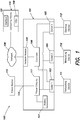
- FIG. 1 is a block diagram of a network system 100 including an Uninterruptible Power Supply (UPS) system 101 in accordance with aspects of the present invention.
- the UPS system 101 includes a power input 115, power circuitry 117, a network module 102, a first outlet 103, a second outlet 104, a third outlet 105, a controller 106, and a battery 107.
- the controller 106 is coupled to the first outlet 103, the second outlet 104, the third outlet 105, and the network module 102.
- the controller 106 is also coupled to the power circuitry 117.
- the network module 102 is configured to be coupled to an external computing device 110 via a network 108.
- the first outlet 103 is configured to be coupled to a first load 111.
- the second outlet 104 is configured to be coupled to a second load 112.
- the third outlet 105 is configured to be coupled to a third load 113.
- the power input 115 of the UPS 101 is configured to be coupled to a power source 114.
- the power circuitry 117 is coupled between the power input 115 and the outlets 103, 104, 105.
- the power circuitry 117 is also coupled to the battery 107.
- the UPS 101 is configured to receive, at the input 115, input power from the power source 114. If the controller 106 determines that the input power is acceptable (e.g., at least at a desired level), the controller 106 operates the power circuitry 117 to provide desired output power to each outlet 103, 104, 105 derived from the input power. If the input power is acceptable, the controller 106 may also operate the power circuitry 117 to provide power to the battery 107 to charge the battery 107. If the controller 106 determines that the input power is unacceptable (e.g., below the desired level), the controller 106 operates the power circuitry 117 to provide desired output power to each outlet 103, 104, 105 derived from backup power provided by the battery 107. According to one embodiment, the power circuitry 117 includes conversion circuitry (e.g., at least one converter and/or an inverter) that is operated by the controller 106 to generate regulated output power from the input power and/or the backup power.
- conversion circuitry e.g., at least one
- the controller 106 is configured to communicate with a management system 110 via the network module 102 and the network 108.
- the management system 110 is a computing device 110.
- the computing device 110 is an operator's computer system; however, in other embodiments, the computing device 110 may be any other type of system capable of communicating with the UPS 101 (e.g., a mobile phone, tablet computer, etc.).
- the network 108 is the Internet; however, in other embodiments, the network 108 may be any other type of Wide Area Network (WAN).
- the network 108 is a Local Area Network (LAN).
- the network 108 may be any other type of network capable of facilitating communication between the UPS 101 and the computing device 110.
- the controller 106 is configured to communicate with any other type of management system that is configured to provide signals to the UPS 101 to control operation of the UPS 101.
- the controller 106 is configured to communicate with any number of different external systems (e.g., computing devices, management systems, etc.) via the network module 102 and the network 108.
- the controller 106 provides a UPS management UI to the computing device 110 via the network module 102 and the network 108.
- the UPS management UI is displayed to an operator via a Video Display Unit (VDU) 109.
- VDU Video Display Unit
- the operator can interact with the UPS management UI via an interface 121 (e.g., a keypad, touchpad, keyboard, mouse, etc.) of the computing device 110.
- the UPS management UI allows the operator to identify which type of equipment (e.g., network based vs. non-network based) is plugged into each outlet 103, 104, 105. Based on the equipment identification by the operator, the UPS management UI displays selectable feature options for each outlet that are appropriate for the equipment type plugged into each outlet. The UPS management UI hides (i.e., does not display) feature options that are not appropriate for each outlet. For example, if a piece of network equipment is coupled to the first outlet 103, the UPS management UI may display a selectable rebooting feature in relation to the first outlet 103 and hide a timer feature. Alternatively if a non-network piece of equipment is coupled to the third outlet 105, the UPS management UI may display the timer feature and hide the rebooting feature with respect to the third outlet 105.
- type of equipment e.g., network based vs. non-network based
- the UPS management UI simplifies the selection of an appropriate outlet configuration for the UPS 101 and minimizes the potential use of an outlet configuration that may lead to network connectivity issues.
- the controller 106 also monitors commands input to the UPS 101 by the operator (or some other external system) and, based on the outlet configuration set by the operator, rejects or blocks incorrect or inappropriate commands. For example, if the first outlet 103 is identified by the operator as being coupled to a network device and the controller receives a command to implement a timer feature for the first outlet 103, the controller 105 rejects the command as a timer feature cannot be implemented for a network device. Similarity, if the third outlet 105 is identified by the operator as being coupled to a non-network device and the controller receives a command to implement a rebooting feature for the third outlet 105 the controller 105 rejects the command as a rebooting feature cannot be implemented for a non-network device.
- the controller 106 can minimize errors by the operator and also prevent conflicting commands from multiple different external computing devices (e.g., from multiple different operators or management systems) from leading to inappropriate operation of the UPS 101.
- the controller 106 can also provide additional network security as service attacks from an external system which are intended to shut down a network configured outlet are rejected.
- the UPS 101 includes a mix of static and dynamic outlets.
- a static outlet is an outlet that is permanently configured to be coupled to a certain type of load.
- the first outlet 103 of the UPS 101 is a static outlet permanently configured to be coupled to a piece of network equipment and the third outlet 105 is a static outlet permanently configured to be coupled to a piece of non-network equipment.
- the second outlet 104 is a dynamic outlet which may be identified, by the operator, as being coupled to a network or non-network piece of equipment.
- the UPS 101 may include any number of static and/or dynamic outlets.
- the UPS management UI automatically displays, with respect to the first static outlet 103, selectable features appropriate for an outlet coupled to a network device and automatically displays, with respect to the third static outlet 105, selectable features appropriate for an outlet coupled to a non-network device.
- the operator utilizes the UPS management UI to identify whether the second dynamic outlet 104 is coupled to a network or non-network piece of equipment. Based on the identification of the type of equipment that is coupled to the second outlet 104, the UPS management UI automatically displays the appropriate feature options for the identified type of equipment.
- FIG. 2A is a screenshot view of one embodiment of a network configuration screen 200 of the UPS management UI.
- the operator can access the network configuration screen 200 by selecting a network configuration button 201.
- the network outlet selection screen 200 includes a network outlet selection area 202.
- the network outlet selection area 202 includes radio buttons 204a, 204b which allow an operator to select which outlets of the UPS 101 are coupled to network equipment (i.e., are network based outlets). According to one embodiment and as shown in FIG.
- the network outlet selection area 202 includes a first radio button 204a that allows an operator to identify the first outlet 103 and the second outlet 104 as being coupled to network equipment and a second radio button 204b that allows an operator to identify only the first outlet 103 as being coupled to a network device.
- the network outlet selection area 202 does not provide the third outlet 105 as a selectable option as the third outlet 105 is a static switch that is permanently configured to be coupled to non-network equipment (i.e., is a non-network outlet).
- the network outlet selection area 202 also does not allow an operator to deselect the first outlet 103 as being coupled to a network piece of equipment as the first outlet 103 is a static outlet that is permanently configured to be coupled to network equipment.
- the UPS management UI has a default mode in which it assumes that the first outlet 103 is coupled to a first piece of network equipment (e.g., a modem) and the second outlet 104 is coupled to a second piece of network equipment (e.g., a router).
- the first radio button 204a in the network outlet selection area 202 is automatically selected, indicating that the first outlet 103 and the second outlet 104 are each coupled to a different piece of network equipment.
- the operator may also manually select the first radio button 204a, indicating that the first outlet 103 and the second outlet 104 are each coupled to a different piece of network equipment.
- the operator may select the second radio button 204b to indicate that only the first outlet 102 is a network configured outlet.
- FIG. 2B is a screenshot view of one embodiment of the network configuration screen 200 of the UPS management UI illustrating only the first outlet 103 as being identified as a network outlet.
- the network outlet selection screen 200 includes a network outlet feature selection area 206 that lists the selectable features that are available to be implemented in the selected network based outlets.
- the network outlet feature selection area 206 includes a switch 207 corresponding to each available feature that allows the operator to choose whether that feature should be implemented with the network outlets, or not.
- the network outlet feature selection area 206 includes a rebooting feature (i.e., "Watchdog") that can be implemented in any of the network configured outlets.
- An operator may utilize the switch 207 to activate or deactivate the rebooting feature with regard to the network configured outlets.
- the controller 106 groups the first and second outlets 103, 104 together, applies the same settings to both outlets 103, 104, and displays the same selectable features for both outlets 103, 104. For example, if the first radio button 204a is selected and the operator utilizes the switch 207 to turn on the rebooting feature, the rebooting feature is implemented in both the first outlet 103 and the second outlet 104. Also when the first radio button 204a is selected, the controller 106 prevents a timer feature from being implemented in either the first outlet 104 or the second outlet 104. FIG.
- 3A is a screenshot view of one embodiment of the network configuration screen 200 of the UPS management UI during a transition period after the operator has selected, via switch 207, to implement the rebooting feature in the first outlet 103 and the second outlet 104. After the rebooting feature has been implemented in the first outlet 103 and the second outlet 104, the operator may turn off the rebooting feature by again utilizing the switch 207.
- the second radio button 204b When the second radio button 204b is selected, only the first outlet 103 is identified as being coupled to a piece of network equipment (e.g., a combined modem/router) and the second outlet 104 is identified as being coupled to piece of non-network equipment.
- a piece of network equipment e.g., a combined modem/router
- the controller 106 decouples the operation of the outlets 103, 104, maintains the implementation of any previously selected network appropriate features (e.g., the rebooting feature) with the first outlet 103, deactivates any network appropriate features with regard to the second outlet 104, prevents any network appropriate features (e.g., a rebooting feature) from being implemented in the second outlet 104, and prevents any non-network appropriate features (e.g., a timer) from being implement in the first outlet 103.
- the operator may choose to activate or deactivate any network appropriate feature with respect to the first outlet.
- FIG. 3B is a screenshot view of one embodiment of the network configuration screen 200 of the UPS management UI during a transition period after the operator has selected, via switch 207, to implement the rebooting feature in only the first outlet 103. After the rebooting feature has been implemented in the first outlet 103, the operator may turn off the rebooting feature by again utilizing the switch 207.
- the network outlet selection screen 200 also includes a non-network feature selection area 208 that lists the current non-network based outlets based on the configuration of network outlets set by the operator. For example, as shown in FIG. 2A , when the operator sets the first outlet 103 and the second outlet 10 as network outlets, the non-network feature selection area 208 identifies the third outlet 105 as being coupled to a non-network piece of equipment. As shown in FIG. 2B , when the operator sets only the first outlet 103 as a network outlet, the non-network feature selection area 208 identifies the second outlet 104 and the third outlet 105 as being coupled to non-network pieces of equipment. By selecting the non-network feature selection area 208, the operator can choose to implement non-network appropriate features (e.g., a timer) in any of the non-network configured outlets.
- non-network appropriate features e.g., a timer
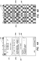
- FIG. 4A is a screenshot view of one embodiment of the network configuration screen 200 of the UPS management UI where only the first outlet 103 is identified as a network outlet and the rebooting feature is implemented in the first outlet 103.
- the non-network feature selection area 208 lists the second outlet 104 and the third outlet 105 as non-network outlets.
- FIG. 4B is a screenshot view of one embodiment of the network configuration screen 200 of the UPS management UI during a transition period after the operator has selected the first radio button 204a to group the first outlet 103 and the second outlet 104 as network outlets. Once the first outlet 103and the second outlet 104 are grouped as network outlets, only the third outlet 105 is displayed in the non-network feature selection area 208 as a non-network outlet.
- FIG. 4B is a screenshot view of one embodiment of the network configuration screen 200 of the UPS management UI during a transition period after the operator has utilized the switch 207 to deactivate the rebooting feature with regard to the first outlet 103 and the second outlet 105.
- the operator can choose to implement non-network appropriate features in any of the non-network configured outlets.
- selection of the non-network feature selection area 208 allows the operator to implement timer features for any of the non-network configured outlets. For example, if the second radio button 204b is selected such that the first outlet is identified as a network outlet, the second outlet 104 and the third outlet 105 are identified as non-network outlets and are displayed in the non-network feature selection area 208.
- FIG. 5 is a screenshot view of one embodiment of a timer selection screen 500.
- the timer selection screen 500 includes a timer configuration button 502 corresponding to the second outlet 104 and a timer configuration button 504 corresponding to the third outlet 105.
- the timer configuration button 502 By selecting the timer configuration button 502, the operator can set a timer feature value for the second outlet 104 and by selecting the timer configuration button 504, the operator can set a timer feature value for the third outlet 105.
- the set timer feature values for each outlet determine a scheduled period of time that the operational state of the non-network outlet should be alternated (e.g., turned from on to off or off to on).
- the timer selection screen 500 also includes a time zone selection button 506 which, when selected by the operator, allows the operator to set an appropriate time zone for the UPS 101.
- FIG. 6A is a screenshot view of one embodiment of an outlet control screen 600.
- An operator can access the outlet control screen 600 by selecting the outlet control button 601.
- the outlet control screen 600 includes a network outlet control options section 602 and a non-network outlet control options section 604.
- the network outlet control options section 602 includes appropriate command options for the network configured outlets and the non-network outlet control options section 604 include appropriate command options for the non-network configured outlets.
- the network outlet control options section 602 includes a listing of the network configured outlets, an identification of the features currently activated for each network outlet (e.g., a rebooting feature), and a command button 603 for initiating a command (i.e., sending a command to the controller 106) with regard to the networked outlets.
- the command button 603 is a reboot button that, when selected by the operator, instructs the controller 106 to cycle power to the networked outlets.
- FIG. 6B is a screenshot view of one embodiment of the outlet control screen 600 of the UPS management UI during a transition period after the operator has utilized the switch 603 to initiate a command (i.e., to the controller 106) to cycle power to the first outlet 103 and the second outlet 105.
- the non-network outlet control section 604 includes a listing of the previously configured non-network outlets (as discussed above) and a command button 605 for initiating a command (i.e., sending a command to the controller 106) with regard to the non-networked outlets.
- the command button 605 is a power button 605 that can be used by the operator to immediately alternate an operational state of the associated non-network outlet (e.g., turn on or off the associated outlet).
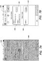
- FIG. 7A is a screenshot view of one embodiment of the outlet control screen 600 of the UPS management UI during a transition period after the operator has utilized the switch 605 to initiate a command (i.e., to the controller 106) to turn off the third outlet 105.
- FIG. 7B is a screenshot view of one embodiment of the outlet control screen 600 of the UPS management UI after the third outlet 105 has been turned off.
- FIG. 8 is a screenshot view of another embodiment of the outlet control screen 600. If the first outlet 103 is identified as a network outlet and the second outlet 104 and third outlet 105 are identified as non-network outlets, the network outlet control options section 602 lists the first outlet 103 as a network outlet and the non-network outlet control section 604 lists the second outlet 104 and the third outlet 105 as non-network outlets. The network outlet control options section 602 also lists any currently active features (e.g., a rebooting feature) with respect to the first outlet 103 and includes the command button 603 for cycling power to the first outlet 103. The non-network outlet control section 604 lists the second outlet 104 and the third outlet 105 as non-network outlets.
- any currently active features e.g., a rebooting feature
- the non-network outlet control section 604 also includes a first command button 605a for initiating a command (i.e., sending a command to the controller 106) with regard to the second outlet 104 and a second command button 605b for initiating a command with regard to the third outlet 105.
- the command buttons 605a, 605b are power buttons
- the operator can use the first command button 605a to turn on/off the second outlet 104 and the second command button 605b to turn on/off the third outlet 105.
- the first command button 605a shows that the second outlet 104 is turned off and the second command button 605b shows that the third outlet 105 is turned on.
- Table 1 Settings/ Control Scenarios/options Outlet 1 Outlet 2 Outlet 3 Network Config. Screen (200) Grouping ON for 1+2. Networking equipment powered by both outlets Rebooting available, Timers not available Timer available, no Rebooting Grouping OFF: Networking equipment powered by outlet 1 only Rebooting available, Timer not available Timer available, no Rebooting Timer available, no Rebooting Outlet Control Screen (600) Grouping ON (1 + 2) Outlet reboot only Outlet On/Off Grouping OFF (1) Outlet reboot only Outlet On/Off Outlet On/Off
- the UPS 101 includes three outlets; however, in other embodiments, any number of outlets may be utilized. As also described above, the UPS 101 includes two static outlets and one dynamic outlet; however, in other embodiments, the UPS 101 may include any number of static and/or dynamic outlets. As also described above, the first outlet 103 of the UPS 101 is a static network configured outlet while the second outlet 104 is a dynamic outlet and the third outlet 105 is a static non-network configured outlet. However, in other embodiments, the configuration of the outlets may be defined in any other appropriate way. For example, where a UPS includes five outlets, any of the five outlets can be identified as a network configured outlet. For example, in one embodiment the first two outlets are identified as network configured outlets. In another embodiment, the third outlet is identified as a network configured outlet. In another embodiment, the fourth and fifth outlets are identified as network configured outlets.
- the management UI allows an operator to identify whether an outlet is coupled to a network based or non-network based piece of equipment and displays appropriate feature options in relation to the outlet based on whether the outlet is network or non-network based.
- the management UI is configured to allow an operator to identify some other characteristic of the type of equipment coupled to an outlet and display appropriate feature options in relation to the outlet based on the identified characteristic.
- the management UI is configured to allow an operator to identify equipment as security system equipment, network drives, printers, Network Attached Storage (NAS), or any other type of equipment that an operator would want to prevent from being inadvertently turned off
- a controller of a UPS provides a UI to an operator that displays appropriate selectable outlet features based on the type of equipment plugged into the outlets of the UPS.
- the controller may be located in a Power Distribution Unit (PDU) and may be configured to provide a PDU management UI to an operator that displays appropriate selectable outlet features (as discussed above) based on the type of equipment plugged into the outlets of the PDU.
- the controller may be similarly located in other power devices such as a power strip, outlet, or any other "smart" power device.
- the management UI is provided to an external display of an operator; however, in other embodiments, the management UI may be provided to a display that is located on the UPS 101 itself.
- Embodiments described herein provide a UPS system that implements appropriate features in an outlet based on the type of equipment the outlet is protecting.
- the UPS system limits the features available for selection by an operator for an outlet and rejects inappropriate commands sent to the outlet based on an outlet configuration defined by an operator.
- the UPS management UI simplifies the selection of an appropriate outlet configuration for the UPS and minimizes the potential use of an outlet configuration that may lead to network connectivity issues, confusion, or even damaged equipment.
- the UPS management UI By utilizing the equipment identification provided by the operator to only display appropriate control/command options with respect to each outlet, the UPS management UI also minimizes incorrect or accidental operation of the UPS by the operator. Also, by rejecting incorrect or inappropriate commands based on the set configuration of the outlets, errors by the operator can be minimized and conflicting commands from multiple different external computing devices (e.g., from multiple different operator or management systems) can be prevented.
- a network appropriate feature is a rebooting feature (e.g., a "Watchdog” feature) that when implemented in an outlet, automatically cycles power to the outlet when a network connectivity issue is detected.
- a controller coupled to network equipment attempts to connect to, or "ping", a remote server at predetermined times. If the controller is unable to communicate with the remote server, the controller determines that there is a connectivity issue and cycles power to the network equipment.
- the remote server may not be dedicated to the purpose of determining network resiliency and is instead an external server utilized for a number of different functions.
- the configuration of the non-dedicated remote server may change without notice (e.g., due to a manager of the non-dedicated remote server changing a configuration of the server). This may lead to the controller not being able to communicate with the non-dedicated remote server, even if power to the network equipment is cycled.
- the robustness of the system is limited in that if the single server is unavailable, the networking equipment may be restarted unnecessarily, impacting network connectivity.
- Embodiments described herein provide a network connectivity confirmation system that utilizes multiple dedicated servers to confirm network connectivity.
- multiple dedicated servers rather than a single non-dedicated server (as discussed above), the system provides enhanced network resilience.
- FIG. 9 is a block diagram of one embodiment of a network connectivity confirmation system 900.
- the system 900 includes a network access device 902, a network monitoring device 905, a group of primary servers 907, a group of secondary servers 908, and a network manager 909.
- the network monitoring device 905 is coupled to the network access device 902.
- the network access device 902 is configured to communicate with the group of primary servers 907 and the group of secondary servers 908 via a network 906.
- the network 906 is the Internet; however, in other embodiments, the network 906 may be any other type of LAN or WAN).
- the network manager 909 is configured to communicate with the group of secondary servers 908.
- the network access device 902 is a piece of network equipment (e.g., a server, router, switch, etc) that provides network 906 access to other devices 910.
- the network access device 902 is a piece of network equipment that is coupled to a network configured outlet of the UPS 101 described above with regard to FIG. 1 ; however, in other embodiments, the network access device 902 may be any other type of network access device that provides network excess to other devices and may be included within a UPS.
- the network monitoring device 905 is configured to communicate with the network 906 via a network communication channel 903 and the network access device 902. According to one embodiment, the network monitoring device 905 is also able to control the power that is being supplied to the network access device 902.
- the network monitoring device 905 is located in a UPS (e.g., the UPS 101 discussed above with regard to FIG. 1 ) to which the network access device 902 is coupled.
- the network monitoring device 905 is located in the controller 106 of the UPS 101 or is otherwise in communication with the controller 106; however, in other embodiments, the network monitoring device 905 may be configured in some other appropriate way.
- the network monitoring device 905 In determining the status of the network 906, the network monitoring device 905 periodically attempts to communicate with the primary servers 907.
- the primary servers are servers in which one function of the server is dedicated to determining the operational status of the network 906 (i.e., responding to inquiries from the network monitoring device 905). If the network monitoring device 905 is unsuccessful in communicating with one of the primary servers 907, the network monitoring device 905 periodically attempts to communicate with the secondary servers 908.
- the secondary servers 908 are also servers in which one function of the server is dedicated to determining the operational status of the network 906 (i.e., responding to the inquiries from the network monitoring device 905). If the network monitoring device 905 is also unsuccessful in communicating with one of the secondary servers 908, the network monitoring device 905 identifies that there is a problem with the network 906. Upon identifying that there is a problem with the network 906, the network monitoring device may notify the operator, cycle power to the network access device 902, or take some other appropriate action.
- the network monitoring device 905 in communicating with the primary server(s) 907 and the secondary server(s) 908, utilizes an existing connection that was established over the network 906 for a purpose other than determining network status.
- the existing network connection has multiple servers and fall-back procedures for ensuring that if the network 906 is functioning properly, a connection with at least one server 907, 908 will occur.
- utilizing the existing connection creates a "zero-configuration" situation in which the connection "self-corrects" based on its own internal procedures.
- FIG. 10 is a flow chart 1000 illustrating one embodiment of a network connectivity confirmation process implemented by the system 900.
- the network monitoring device 905 attempts to communicate with (i.e., transmits a signal to) one of the primary servers 907 via the network access device 902 and the network 906.
- the network monitoring device 905 attempts to communicate with the primary server 907 by utilizing the Transmission Control Protocol (TCP) and/or the User Datagram Protocol (UDP); however, in other embodiments, the network monitoring device 905 may utilize some other protocol to communicate with the primary server 907.
- TCP Transmission Control Protocol
- UDP User Datagram Protocol
- the network monitoring device 905 determines if it is able to communicate with the primary server 907. In response to a determination that it is able to communicate with the primary server 907 (i.e., its transmission was successfully received by the primary server 907), the network monitoring device 905 determines that the network 906 is operating correctly and after a period of time, attempts to communicate with the primary server 907 again (at block 1002). In one embodiment, the period of time between connection attempts is configurable by the operator. According to one embodiment the connection established between the network monitoring device 905 and the primary server 907, via the network 906 and the network access device 902, is secure.
- the network monitoring device 905 increments a primary failure counter value.
- the network monitoring device 905 determines if the primary failure counter value is greater than or equal to a primary failure threshold value.
- the primary failure threshold value is ten; however, in other embodiments, the primary failure threshold value may be configured to any other value. Also, in some embodiments, the primary failure threshold value is set by the operator. In response to a determination that the primary failure counter value is less than the primary failure threshold, the network monitoring device 905 returns to block 1002 and attempts to communicate with the primary server 907.
- the network monitoring device 905 attempts to communicate with (i.e., transmits a signal to) a secondary server 908 via the network access device 902 and the network 906.
- the network monitoring device 905 attempts to communicate with the secondary server 908 by utilizing the Transmission Control Protocol (TCP) and/or the User Datagram Protocol (UDP); however, in other embodiments, the network monitoring device 905 may utilize some other protocol to communicate with the secondary server 908.
- the network monitoring device 905 attempts to communicate securely with the secondary server 908.
- the network monitoring device 905 determines if it is able to communicate with the secondary server 908. In response to a determination that it is able to communicate with the secondary server 908 (i.e., its transmission was successfully received), the network monitoring device 905 determines that the network 906 is operating correctly. According to one embodiment, in response to determining that the network 906 is operating correctly, the network monitoring device 905 sends a message to the network manager 909, via the network access device 902, the network 906, and the secondary server 908 confirming that the secondary server 908 is working appropriate and that there may be a problem with the primary server 907.
- the network manager 909 may take action to investigate and/or fix the problem with the primary server 907.
- the message indicating the failure of the primary server 907 may also include a request by the network monitoring device 904 for the assignment of a new primary server 907 to the network access device 902.
- the network manager 909 at block 1016, may assign a new primary server 907 to the network access device 902.
- the network monitoring device 905 may begin the network connection process again and attempt to communicate with the new primary server 907.
- the network manager 909 may automatically assign a new primary server 907 to the network access device 902 upon receiving a message that the original primary server 907 has failed and a specific request from the network monitoring device 904 is not required. According to another embodiment, the network manager 909 may not assign a new primary server 907 to the network access device 902 and, at block 1002, the network monitoring device 905 may again attempt to communicate with the same primary server 907 that previously failed.
- the network monitoring device 905 increments a secondary failure counter value.
- the network monitoring device 905 determines if the secondary failure counter value is greater than or equal to a secondary failure threshold value.
- the secondary failure threshold value is ten; however, in other embodiments, the secondary failure threshold value may be configured to any other value. Also, in some embodiments, the secondary failure threshold value is set by the operator. In response to a determination that the secondary failure counter value is less than the secondary failure threshold, the network monitoring device 905 returns to block 1010 and attempts to communicate with the secondary server 908 again.
- the network monitoring device 905 determines that the network 906 has failed.
- the network monitoring device 905 attempts to take corrective action(s) to fix the network 906.
- the network monitoring device 905 attempts to reset the network connection.
- the network connectivity confirmation process 1000 may be selectively implemented in a network configured outlet of the UPS 101 (shown in FIG. 1 ) by an operator, as discussed above. Upon determining that the network 906 has failed, the network monitoring device 905 may send a command to the controller 106 to cycle power to the outlet of the UPS 101 to which the network access device 902 is coupled. In other embodiments, the network connectivity confirmation process 1000 may be implemented in a network configured outlet of another type of power device (e.g., a power strip, a smart outlet, etc.).
- the network monitoring device 905 may take different corrective measures. For example, in some embodiments the network monitoring device 905 may transmit a message to the network manager 909, may provide a message to an operator's display, or may operate some type of indicator (e.g., a light, sound generator etc.) to indicate that there is a network problem. In other embodiments, upon determining that the network 906 has failed, the network monitoring device 905 performs network analytics on the resulting data.
- some type of indicator e.g., a light, sound generator etc.
- the network connectivity confirmation process 1000 is implemented in a UPS; however, in other embodiments, the network connectivity confirmation process is implemented in some other power device (e.g., a power strip, smart outlet, etc.).
- the network monitoring device is configured to attempt communication with the secondary server only after communication has failed with the primary server a predetermined number of times; however, in other embodiments, the network monitoring device may be configured to attempt communication with the secondary server immediately after a communication failure with the primary server.
- the network monitoring device is configured to identify a network failure only after communication has failed with the secondary server a predetermined number of times; however, in other embodiments, the network monitoring device may identify a network failure immediately after a communication failure with the secondary server.
- the network connectivity confirmation process 1000 may be selectively implemented in a network configured outlet of a power device by an operator (e.g., as discussed above with regard to FIG. 4A ); however, in other embodiments, even though the network connectivity confirmation process 1000 is available as a selectable feature to be implemented in a network configured outlet, the operator may choose not to implement the feature in an outlet and turn the feature off with respect to one or more outlets (e.g., as discussed above with regard to FIG. 4C ).
- network failure is identified after communication attempts to both a dedicated primary server and a dedicated secondary server have failed; however, in at least one embodiment, a network failure may be identified after communication attempts to a single dedicated server fail.
- communication is attempted with a single primary server before communication with a secondary server is attempted; however, in other embodiments, communication is attempted with multiple primary servers before communication is attempted with a secondary server.
- Embodiments described herein provide a network connectivity confirmation system that utilizes multiple servers to confirm network connectivity.
- the system provides enhanced network resilience.
- at least one dedicated server having a predefined relationship with a power device such that the dedicated server won't be reconfigured without notice to the power device, potential uncontrollable errors due to server configuration changes can be minimized.
- the network connectivity confirmation system is less likely to be subject to a successful Distributed Denial of Service (DDoS) attack.
- DDoS Distributed Denial of Service
- FIG. 11 illustrates an example block diagram of computing components forming a system 1100 which may be configured to implement one or more aspects disclosed herein.
- the system 1100 may be communicatively coupled to a controller or included within a controller, and/or configured to provide a management interface to an operator or check the connectivity status of a network as discussed above.
- the system 1100 may include for example a computing platform such as those based on Intel PENTIUM-type processor, Motorola PowerPC, Sun UltraSPARC, Texas Instruments-DSP, Hewlett-Packard PA-RISC processors, or any other type of processor.
- System 1100 may include specially-programmed, special-purpose hardware, for example, an application-specific integrated circuit (ASIC).
- ASIC application-specific integrated circuit
- Various aspects of the present disclosure may be implemented as specialized software executing on the system 1100 such as that shown in FIG. 11 .
- the system 1100 may include a processor/ASIC 1106 connected to one or more memory devices 1110, such as a disk drive, memory, flash memory or other device for storing data. Memory 1110 may be used for storing programs and data during operation of the system 1100.
- Components of the computer system 1100 may be coupled by an interconnection mechanism 1108, which may include one or more buses (e.g., between components that are integrated within a same machine) and/or a network (e.g., between components that reside on separate machines).
- the interconnection mechanism 1108 enables communications (e.g., data, instructions) to be exchanged between components of the system 1100.
- the system 1100 also includes one or more input devices 1104, which may include for example, a keyboard or a touch screen.
- the system 1100 includes one or more output devices 1102, which may include for example a display.
- the computer system 1100 may contain one or more interfaces (not shown) that may connect the computer system 1100 to a communication network, in addition or as an alternative to the interconnection mechanism 1108.
- the system 1100 may include a storage system 1112, which may include a computer readable and/or writeable nonvolatile medium in which signals may be stored to provide a program to be executed by the processor or to provide information stored on or in the medium to be processed by the program.
- the medium may, for example, be a disk or flash memory and in some examples may include RAM or other non-volatile memory such as EEPROM.
- the processor may cause data to be read from the nonvolatile medium into another memory 1110 that allows for faster access to the information by the processor/ASIC than does the medium.
- This memory 1110 may be a volatile, random access memory such as a dynamic random access memory (DRAM) or static memory (SRAM). It may be located in storage system 1112 or in memory system 1110.
- DRAM dynamic random access memory
- SRAM static memory
- the processor 1106 may manipulate the data within the integrated circuit memory 1110 and then copy the data to the storage 1112 after processing is completed.
- a variety of mechanisms are known for managing data movement between storage 1112 and the integrated circuit memory element 1110, and the disclosure is not limited thereto. The disclosure is not limited to a particular memory system 1110 or a storage system 1112.
- the system 1100 may include a computer platform that is programmable using a high-level computer programming language.
- the system 1100 may be also implemented using specially programmed, special purpose hardware, e.g. an ASIC.
- the system 1100 may include a processor 1106, which may be a commercially available processor such as the well-known Pentium class processor available from the Intel Corporation. Many other processors are available.
- the processor 1106 may execute an operating system which may be, for example, a Windows operating system available from the Microsoft Corporation, MAC OS System X available from Apple Computer, the Solaris Operating System available from Sun Microsystems, or UNIX and/or LINUX available from various sources. Many other operating systems may be used.
- the processor and operating system together may form a computer platform for which application programs in high-level programming languages may be written. It should be understood that the disclosure is not limited to a particular computer system platform, processor, operating system, or network. Also, it should be apparent to those skilled in the art that the present disclosure is not limited to a specific programming language or computer system. Further, it should be appreciated that other appropriate programming languages and other appropriate computer systems could also be used.
Landscapes
- Engineering & Computer Science (AREA)
- Power Engineering (AREA)
- Business, Economics & Management (AREA)
- Emergency Management (AREA)
- Environmental & Geological Engineering (AREA)
- Computer Networks & Wireless Communication (AREA)
- Signal Processing (AREA)
- Remote Monitoring And Control Of Power-Distribution Networks (AREA)
- Testing And Monitoring For Control Systems (AREA)
- Power Sources (AREA)
- Stand-By Power Supply Arrangements (AREA)
Claims (14)
- Eine Leistungsvorrichtung, die Folgendes beinhaltet:einen Eingang, der konfiguriert ist, um an eine Leistungsquelle gekoppelt zu werden und Eingangsleistung von der Leistungsquelle zu empfangen;Leistungsbeschaltung, die an den Eingang gekoppelt ist;eine Vielzahl von Anschlüssen;ein Netzwerkmodul, das konfiguriert ist, um an ein Netzwerk gekoppelt zu werden;eine Steuerung, die an die Vielzahl von Anschlüssen, die Leistungsbeschaltung unddas Netzwerkmodul gekoppelt ist, wobei die Steuerung konfiguriert ist zum:Betreiben der Leistungsbeschaltung, um der Vielzahl von Anschlüssen von der Eingangsleistung stammende Ausgangsleistung bereitzustellen;Bereitstellen einer Verwaltungsschnittstelle zu einem Verwaltungssystem über das Netzwerkmodul und das Netzwerk, wobei die Verwaltungsschnittstelle konfiguriert ist, um einem Bediener zu erlauben, eine Angabe einer Art von Ausrüstung, die an jeden der Vielzahl von Anschlüssen gekoppelt ist, bereitzustellen, wobei die Art von Ausrüstung angibt, ob die Ausrüstung netzwerkbasiert oder nicht netzwerkbasiert ist;Anzeigen, über die Verwaltungsschnittstelle, einer Vielzahl von Netzwerkkonfigurationsoptionen in einem Layout, das auf der von dem Bediener bereitgestellten Angabe der Art von Ausrüstung, die an jeden der Vielzahl von Anschlüssen gekoppelt ist, basiert;Anzeigen, über die Verwaltungsschnittstelle, einer ersten Netzwerkkonfigurationsoption, die mit einem ersten der Vielzahl von Anschlüssen assoziiert ist und auf der Angabe der Art von Ausrüstung, die an den ersten der Vielzahl von Anschlüssen gekoppelt ist, basiert und aufgrund dieser Angabe geeignet ist; undVerbergen, über die Verwaltungsschnittstelle in Bezug auf den ersten der Vielzahl von Anschlüssen, einer zweiten Netzwerkkonfigurationsoption, die auf der Angabe der Art von Ausrüstung, die an den ersten der Vielzahl von Anschlüssen gekoppelt ist, basiert und aufgrund dieser Angabe ungeeignet ist.
- Leistungsvorrichtung gemäß Anspruch 1, wobei die Steuerung ferner konfiguriert ist, um in Bezug auf den ersten der Vielzahl von Anschlüssen Steuersignale zurückzuweisen, die der zweiten Netzwerkkonfigurationsoption entsprechen.
- Leistungsvorrichtung gemäß Anspruch 2, wobei die Steuerung ferner konfiguriert ist, um von einem Bediener über die Verwaltungsschnittstelle die Angabe zu empfangen, ob jeder der Vielzahl von Anschlüssen an einen netzwerkbasierten Ausrüstungsgegenstand oder einen nicht netzwerkbasierten Ausrüstungsgegenstand gekoppelt ist, wobei als Reaktion auf eine Angabe, dass der erste der Vielzahl von Anschlüssen an einen netzwerkbasierten Ausrüstungsgegenstand gekoppelt ist, die Steuerung ferner konfiguriert ist, um über die Verwaltungsschnittstelle eine Darstellung der ersten Netzwerkkonfigurationsoption für den ersten der Vielzahl von Anschlüssen anzuzeigen, und wobei die erste Netzwerkkonfigurationsoption eine Neustartmerkmalsimplementierungsoption umfasst und als Reaktion darauf, dass der Bediener über die Verwaltungsschnittstelle die Neustartmerkmalsimplementierungsoption in Bezug auf den ersten der Vielzahl von Anschlüssen auswählt, die Steuerung ferner konfiguriert ist zum:periodischen Prüfen des Status des Netzwerks; undals Reaktion auf eine Feststellung, dass das Netzwerk gestört ist, Betreiben des ersten der Vielzahl von Anschlüssen, um an dem netzwerkbasierten Ausrüstungsgegenstand ein Schaltspiel auszuführen.
- Leistungsvorrichtung gemäß Anspruch 3, wobei bei der periodischen Prüfung des Status des Netzwerks die Steuerung konfiguriert ist zum:Versuchen, mit mindestens einem Server über das Netzwerk zu kommunizieren; undals Reaktion auf eine Feststellung, dass die Kommunikation mit dem mindestens einen Server gestört ist, Identifizieren, dass das Netzwerk gestört ist, undwobei die Steuerung bei dem Versuch, mit dem mindestens einen Server über das Netzwerk zu kommunizieren, ferner konfiguriert ist zum:Versuchen, mit einem primären Server über das Netzwerk zu kommunizieren;als Reaktion auf eine Feststellung, dass die Kommunikation mit dem primären Server gestört ist, Versuchen, mit einem sekundären Server über das Netzwerk zu kommunizieren; undals Reaktion auf eine Feststellung, dass die Kommunikation mit dem sekundären Server gestört ist, Identifizieren, dass das Netzwerk gestört ist.
- Leistungsvorrichtung gemäß Anspruch 3, wobei als Reaktion darauf, dass der Bediener über die Verwaltungsschnittstelle die Neustartmerkmalsimplementierungsoption für den ersten der Vielzahl von Anschlüssen auswählt, die Steuerung ferner konfiguriert ist, um über die Verwaltungsschnittstelle eine Neustartsteuerungsoption bereitzustellen, und wobei als Reaktion darauf, dass der Bediener über die Verwaltungsschnittstelle die Neustartsteuerungsoption auswählt, die Steuerung ferner konfiguriert ist, um den ersten der Vielzahl von Anschlüssen zu betreiben, um an dem netzwerkbasierten Ausrüstungsgegenstand ein Schaltspiel auszuführen.
- Leistungsvorrichtung gemäß Anspruch 3, wobei als Reaktion auf eine Angabe, dass der erste der Vielzahl von Anschlüssen an einen nicht netzwerkbasierten Ausrüstungsgegenstand gekoppelt ist, die Steuerung ferner konfiguriert ist, um über die Verwaltungsschnittstelle eine Darstellung der zweiten Netzwerkkonfigurationsoption für den ersten der Vielzahl von Anschlüssen anzuzeigen, und
wobei die zweite Netzwerkkonfigurationsoption eine Timermerkmalsimplementierungsoption umfasst und als Reaktion darauf, dass der Bediener über die Verwaltungsschnittstelle die Timermerkmalsimplementierungsoption in Bezug auf den ersten der Vielzahl von Anschlüssen auswählt, die Steuerung ferner konfiguriert ist, um einen Betriebszustand des ersten der Vielzahl von Anschlüssen während einer geplanten Zeitperiode zu wechseln. - Leistungsvorrichtung gemäß Anspruch 6, wobei als Reaktion auf eine Angabe, dass der erste der Vielzahl von Anschlüssen an einen nicht netzwerkbasierten Ausrüstungsgegenstand gekoppelt ist, die Steuerung ferner konfiguriert ist, um über die Verwaltungsschnittstelle eine Darstellung einer Leistungssteuerungsoption für den ersten der Vielzahl von Anschlüssen bereitzustellen, und
wobei als Reaktion darauf, dass der Bediener über die Verwaltungsschnittstelle die Leistungssteuerungsoption auswählt, die Steuerung ferner konfiguriert ist, um einen Betriebszustand des ersten der Vielzahl von Anschlüssen zu wechseln. - Leistungsvorrichtung gemäß Anspruch 6, wobei die Steuerung ferner konfiguriert ist, um von dem Bediener über die Verwaltungsschnittstelle eine Angabe zu empfangen, um den ersten der Vielzahl von Anschlüssen mit einem zweiten der Vielzahl von Anschlüssen zu gruppieren,
wobei die Steuerung bei der Gruppierung ferner konfiguriert ist, um den zweiten der Vielzahl von Anschlüssen als an dieselbe Art von Ausrüstung wie der erste der Vielzahl von Anschlüssen gekoppelt zu identifizieren und dem Bediener über die Verwaltungsschnittstelle eine Darstellung einer gleichen der Vielzahl von Netzwerkkonfigurationsoptionen für den ersten der Vielzahl von Anschlüssen und den zweiten der Vielzahl von Anschlüssen bereitzustellen. - Ein Verfahren zum Betreiben einer Leistungsvorrichtung, wobei die Leistungsvorrichtung eine Vielzahl von Anschlüssen und eine an die Vielzahl von Anschlüssen gekoppelte Steuerung beinhaltet, wobei das Verfahren Folgendes beinhaltet:Bereitstellen, durch die Steuerung, einer Verwaltungsschnittstelle für einen Bediener; Empfangen, durch die Steuerung über die Verwaltungsschnittstelle, einer Angabe einer Art von Ausrüstung, die an jeden der Vielzahl von Anschlüssen gekoppelt ist; undAnzeigen, über die Verwaltungsschnittstelle, einer Vielzahl von Netzwerkkonfigurationsoptionen in einem Layout, das auf der Angabe der Art von Ausrüstung, die an jeden der Vielzahl von Anschlüssen gekoppelt ist, basiert und aufgrund dieser Angabe geeignet ist, wobei die Art der Ausrüstung angibt, ob die Ausrüstung netzwerkbasiert oder nicht netzwerkbasiert ist;Anzeigen, über die Verwaltungsschnittstelle, einer ersten Netzwerkkonfigurationsoption für jeden der Vielzahl von Anschlüssen, der als an einen netzwerkbasierten Ausrüstungsgegenstand gekoppelt angegeben wird;Anzeigen, über die Verwaltungsschnittstelle, einer zweiten Netzwerkkonfigurationsoption für jeden der Vielzahl von Anschlüssen, der als an einen nicht netzwerkbasierten Ausrüstungsgegenstand gekoppelt angegeben wird;Nichtanzeigen, über die Verwaltungsschnittstelle, der zweiten Netzwerkkonfigurationsoption für jeden der Vielzahl von Anschlüssen, der als an einen netzwerkbasierten Ausrüstungsgegenstand gekoppelt angegeben wird; undNichtanzeigen, über die Verwaltungsschnittstelle, der ersten Netzwerkkonfigurationsoption für jeden der Vielzahl von Anschlüssen, der als an einen nicht netzwerkbasierten Ausrüstungsgegenstand gekoppelt angegeben wird.
- Verfahren gemäß Anspruch 9, das ferner Folgendes beinhaltet:Blockieren, mit der Steuerung, jeglicher Steuersignale, entsprechend der zweiten Netzwerkkonfigurationsoption, für jeden aus der Vielzahl von Anschlüssen, der als an einen netzwerkbasierten Ausrüstungsgegenstand gekoppelt angegeben wird; undBlockieren, mit der Steuerung, jeglicher Steuersignale, entsprechend der ersten Netzwerkkonfigurationsoption, für jeden der Vielzahl von Anschlüssen, der als an einen nicht netzwerkbasierten Ausrüstungsgegenstand gekoppelt angegeben wird.
- Verfahren gemäß Anspruch 9, das ferner Folgendes beinhaltet:wobei das Anzeigen einer ersten Netzwerkkonfigurationsoption das Anzeigen einer Neustartmerkmalsimplementierungsoption über die Verwaltungsschnittstelle umfasst;wobei das Anzeigen einer zweiten Netzwerkkonfigurationsoption das Anzeigen einer Timermerkmalsimplementierungsoption über die Verwaltungsschnittstelle umfasst;periodisches Prüfen des Status des Netzwerks als Reaktion darauf, dass der Bediener die Neustartmerkmalsimplementierungsoption in Bezug auf einen ersten der Vielzahl von Anschlüssen auswählt; undals Reaktion auf eine Feststellung, dass das Netzwerk gestört ist, Betreiben des ersten der Vielzahl von Anschlüssen, um an dem netzwerkbasierten Ausrüstungsgegenstand, der an den ersten der Vielzahl von Anschlüssen gekoppelt ist, ein Schaltspiel auszuführen.
- Verfahren gemäß Anspruch 9, das ferner Folgendes beinhaltet:wobei das Anzeigen einer ersten Netzwerkkonfigurationsoption das Anzeigen einer Neustartmerkmalsimplementierungsoption über die Verwaltungsschnittstelle umfasst;wobei das Anzeigen einer zweiten Netzwerkkonfigurationsoption das Anzeigen einer Timermerkmalsimplementierungsoption über die Verwaltungsschnittstelle umfasst;Bereitstellen einer Neustartsteuerungsoption als Reaktion darauf, dass der Bediener die Neustartmerkmalsimplementierungsoption in Bezug auf einen ersten der Vielzahl von Anschlüssen auswählt; undAusführen eines Schaltspiels an dem netzwerkbasierten Ausrüstungsgegenstand, der an den ersten der Vielzahl von Anschlüssen gekoppelt ist, als Reaktion darauf, dass der Bediener die Neustartsteuerungsoption auswählt.
- Verfahren gemäß Anspruch 9, das ferner Folgendes beinhaltet:wobei das Anzeigen einer ersten Netzwerkkonfigurationsoption das Anzeigen einer Neustartmerkmalsimplementierungsoption über die Verwaltungsschnittstelle umfasst;wobei das Anzeigen einer zweiten Netzwerkkonfigurationsoption das Anzeigen einer Timermerkmalsimplementierungsoption über die Verwaltungsschnittstelle umfasst;Wechseln eines Betriebszustands eines ersten der Vielzahl von Anschlüssen während einer geplanten Zeitperiode als Reaktion darauf, dass der Bediener die Timermerkmalsimplementierungsoption in Bezug auf den ersten der Vielzahl von Anschlüssen auswählt;Bereitstellen, über die Verwaltungsschnittstelle als Reaktion auf eine Angabe, dass der erste der Vielzahl von Anschlüssen an einen nicht netzwerkbasierten Ausrüstungsgegenstand gekoppelt ist, einer Leistungssteuerungsoption in Bezug auf den ersten der Vielzahl von Anschlüssen; undWechseln eines Betriebszustands des ersten der Vielzahl von Anschlüssen als Reaktion darauf, dass der Bediener die Leistungssteuerungsoption auswählt.
- Verfahren gemäß Anspruch 9, das ferner Folgendes beinhaltet:Gruppieren eines ersten der Vielzahl von Anschlüssen mit einem zweiten der Vielzahl von Anschlüssen; undals Reaktion auf das Gruppieren des ersten der Vielzahl von Anschlüssen mit dem zweiten der Vielzahl von Anschlüssen, Identifizieren des ersten der Vielzahl von Anschlüssen als an eine gleiche Art von Ausrüstung wie der zweite der Vielzahl von Anschlüssen gekoppelt und Bereitstellen einer gleichen der Vielzahl von Netzwerkkonfigurationsoptionen sowohl für den ersten der Vielzahl von Anschlüssen als auch für den zweiten der Vielzahl von Anschlüssen.
Applications Claiming Priority (1)
| Application Number | Priority Date | Filing Date | Title |
|---|---|---|---|
| US14/739,466 US9847672B2 (en) | 2015-06-15 | 2015-06-15 | System and method to improve network reliability |
Publications (2)
| Publication Number | Publication Date |
|---|---|
| EP3107185A1 EP3107185A1 (de) | 2016-12-21 |
| EP3107185B1 true EP3107185B1 (de) | 2021-05-19 |
Family
ID=56131396
Family Applications (1)
| Application Number | Title | Priority Date | Filing Date |
|---|---|---|---|
| EP16174265.5A Active EP3107185B1 (de) | 2015-06-15 | 2016-06-13 | System und verfahren zur verbesserung der netzzuverlässigkeit |
Country Status (4)
| Country | Link |
|---|---|
| US (1) | US9847672B2 (de) |
| EP (1) | EP3107185B1 (de) |
| JP (1) | JP6789685B2 (de) |
| CA (1) | CA2933115C (de) |
Families Citing this family (3)
| Publication number | Priority date | Publication date | Assignee | Title |
|---|---|---|---|---|
| TWI552475B (zh) * | 2015-09-16 | 2016-10-01 | 碩天科技股份有限公司 | 可管理剩餘電源的電源分配單元 |
| US10439914B2 (en) | 2017-02-16 | 2019-10-08 | Schneider Electric It Corporation | System and method to determine and repair network connection problems |
| US10992171B2 (en) * | 2018-05-25 | 2021-04-27 | Schneider Electric It Corporation | Uninterruptible Power Supply with wirelessly configurable operational parameters |
Family Cites Families (18)
| Publication number | Priority date | Publication date | Assignee | Title |
|---|---|---|---|---|
| CA2428285A1 (en) | 2002-05-06 | 2003-11-06 | Cyber Switching, Inc. | Method and/or system and/or apparatus for multiple interface remotely configurable power supply |
| US8042049B2 (en) * | 2003-11-03 | 2011-10-18 | Openpeak Inc. | User interface for multi-device control |
| US20050206241A1 (en) | 2004-03-17 | 2005-09-22 | Piyush Saxena | Web-enabled UPS |
| US7646107B2 (en) * | 2004-09-30 | 2010-01-12 | Targus Group Internatnional, Inc. | Programmable power adaptor |
| JP4446854B2 (ja) * | 2004-10-12 | 2010-04-07 | 九州電力株式会社 | 電源タップ |
| US8365018B2 (en) * | 2007-06-19 | 2013-01-29 | Sand Holdings, Llc | Systems, devices, agents and methods for monitoring and automatic reboot and restoration of computers, local area networks, wireless access points, modems and other hardware |
| US8195215B2 (en) * | 2008-12-18 | 2012-06-05 | Motorola Solutions, Inc. | Method and system for forming a communication group for content distribution related to an event |
| US9595742B2 (en) | 2009-03-27 | 2017-03-14 | Schneider Electric It Corporation | System and method for replacing a battery in an uninterruptible power supply |
| US9231439B2 (en) | 2009-03-27 | 2016-01-05 | Schneider Electric It Corporation | System and method for estimating an efficiency of a power device |
| US8732602B2 (en) | 2009-03-27 | 2014-05-20 | Schneider Electric It Corporation | System and method for altering a user interface of a power device |
| US8476787B2 (en) | 2009-03-27 | 2013-07-02 | Schneider Electric It Corporation | System and method for changing power states of a power device |
| US8386809B2 (en) | 2009-03-27 | 2013-02-26 | Schneider Electric It Corporation | System and method for configuring a power device |
| US8639953B2 (en) | 2009-03-27 | 2014-01-28 | Schneider Electric It Corporation | System and method for gathering information using a power device wherein information is associated with at least one external load |
| CA2766807A1 (en) * | 2009-06-25 | 2010-12-29 | Server Technology, Inc. | Power distribution apparatus with input and output power sensing and method of use |
| US8204990B1 (en) | 2011-10-06 | 2012-06-19 | James Avery | Power cycler with internet connectivity monitor |
| GB2504056A (en) * | 2012-04-27 | 2014-01-22 | Vioearth Holdings Ltd | Energy saving device with intelligent power control |
| WO2014163604A1 (en) | 2013-03-31 | 2014-10-09 | Schneider Electric It Corporation | System and method for configuring ups outlets |
| US9485718B2 (en) * | 2013-09-13 | 2016-11-01 | Qualcomm Incorporated | Out-of-service recovery for a multi-SIM wireless device |
-
2015
- 2015-06-15 US US14/739,466 patent/US9847672B2/en active Active
-
2016
- 2016-06-13 EP EP16174265.5A patent/EP3107185B1/de active Active
- 2016-06-14 JP JP2016117750A patent/JP6789685B2/ja active Active
- 2016-06-14 CA CA2933115A patent/CA2933115C/en active Active
Non-Patent Citations (1)
| Title |
|---|
| None * |
Also Published As
| Publication number | Publication date |
|---|---|
| JP6789685B2 (ja) | 2020-11-25 |
| US9847672B2 (en) | 2017-12-19 |
| CA2933115C (en) | 2024-05-07 |
| CA2933115A1 (en) | 2016-12-15 |
| US20160365750A1 (en) | 2016-12-15 |
| EP3107185A1 (de) | 2016-12-21 |
| JP2017004531A (ja) | 2017-01-05 |
Similar Documents
| Publication | Publication Date | Title |
|---|---|---|
| US20220285981A1 (en) | Contraband detection through smart power components | |
| US8649270B2 (en) | Dynamic network configuration | |
| US11848889B2 (en) | Systems and methods for improved uptime for network devices | |
| US11223515B2 (en) | Cluster system, cluster system control method, server device, control method, and non-transitory computer-readable medium storing program | |
| CA2933115C (en) | System and method to improve network reliability | |
| MX2014013057A (es) | Dispositivo de ahorro de energia y/o de seguridad. | |
| EP3865998A1 (de) | Cluster-managementverfahren, vorrichtung und system | |
| CN107453888B (zh) | 高可用性的虚拟机集群的管理方法及装置 | |
| EP4054036A1 (de) | Verfahren, gerät und vorrichtung zur identifizierung von schutzschaltern | |
| EP3364518B1 (de) | System und verfahren zum erkennen und reparieren von netzwerkverbindungsproblemen | |
| US10139878B2 (en) | Systems and methods for extended power performance capability discovery for a modular chassis | |
| US11093014B2 (en) | Method for monitoring, control and graceful shutdown of control and/or computer units | |
| WO2017215672A1 (zh) | Poe系统中的供电方法和供电设备 | |
| RU2703340C1 (ru) | Устройство обработки информации, способное легко конфигурировать настройку на инфраструктуре, подлежащей использованию, способ управления для этого и носитель данных | |
| US20220263726A1 (en) | Controlling cognitive functions in a network | |
| EP3713265B1 (de) | Kanalkonfigurationsverfahren und basisstation | |
| WO2016068973A1 (en) | Analysis for multi-node computing systems | |
| JP7575156B2 (ja) | 無線基地局装置 | |
| US20170078450A1 (en) | Remote power management | |
| CN111132106A (zh) | 一种终端设备管理方法、系统、装置及存储介质 | |
| KR20180135330A (ko) | 가상화 기반 재난 방송 시스템 | |
| HK40033392A (en) | Service kiosk access |
Legal Events
| Date | Code | Title | Description |
|---|---|---|---|
| PUAI | Public reference made under article 153(3) epc to a published international application that has entered the european phase |
Free format text: ORIGINAL CODE: 0009012 |
|
| STAA | Information on the status of an ep patent application or granted ep patent |
Free format text: STATUS: REQUEST FOR EXAMINATION WAS MADE |
|
| 17P | Request for examination filed |
Effective date: 20160613 |
|
| AK | Designated contracting states |
Kind code of ref document: A1 Designated state(s): AL AT BE BG CH CY CZ DE DK EE ES FI FR GB GR HR HU IE IS IT LI LT LU LV MC MK MT NL NO PL PT RO RS SE SI SK SM TR |
|
| AX | Request for extension of the european patent |
Extension state: BA ME |
|
| STAA | Information on the status of an ep patent application or granted ep patent |
Free format text: STATUS: EXAMINATION IS IN PROGRESS |
|
| 17Q | First examination report despatched |
Effective date: 20180213 |
|
| GRAP | Despatch of communication of intention to grant a patent |
Free format text: ORIGINAL CODE: EPIDOSNIGR1 |
|
| STAA | Information on the status of an ep patent application or granted ep patent |
Free format text: STATUS: GRANT OF PATENT IS INTENDED |
|
| INTG | Intention to grant announced |
Effective date: 20201217 |
|
| GRAS | Grant fee paid |
Free format text: ORIGINAL CODE: EPIDOSNIGR3 |
|
| GRAA | (expected) grant |
Free format text: ORIGINAL CODE: 0009210 |
|
| STAA | Information on the status of an ep patent application or granted ep patent |
Free format text: STATUS: THE PATENT HAS BEEN GRANTED |
|
| AK | Designated contracting states |
Kind code of ref document: B1 Designated state(s): AL AT BE BG CH CY CZ DE DK EE ES FI FR GB GR HR HU IE IS IT LI LT LU LV MC MK MT NL NO PL PT RO RS SE SI SK SM TR |
|
| REG | Reference to a national code |
Ref country code: GB Ref legal event code: FG4D |
|
| REG | Reference to a national code |
Ref country code: CH Ref legal event code: EP |
|
| REG | Reference to a national code |
Ref country code: DE Ref legal event code: R096 Ref document number: 602016057951 Country of ref document: DE |
|
| REG | Reference to a national code |
Ref country code: AT Ref legal event code: REF Ref document number: 1394937 Country of ref document: AT Kind code of ref document: T Effective date: 20210615 |
|
| REG | Reference to a national code |
Ref country code: IE Ref legal event code: FG4D |
|
| REG | Reference to a national code |
Ref country code: DE Ref legal event code: R081 Ref document number: 602016057951 Country of ref document: DE Owner name: SCHNEIDER ELECTRIC IT CORP., FOXBORO, US Free format text: FORMER OWNER: SCHNEIDER ELECTRIC IT CORP., WEST KINGSTON, RI, US |
|
| REG | Reference to a national code |
Ref country code: LT Ref legal event code: MG9D |
|
| REG | Reference to a national code |
Ref country code: AT Ref legal event code: MK05 Ref document number: 1394937 Country of ref document: AT Kind code of ref document: T Effective date: 20210519 |
|
| REG | Reference to a national code |
Ref country code: NL Ref legal event code: MP Effective date: 20210519 |
|
| PG25 | Lapsed in a contracting state [announced via postgrant information from national office to epo] |
Ref country code: HR Free format text: LAPSE BECAUSE OF FAILURE TO SUBMIT A TRANSLATION OF THE DESCRIPTION OR TO PAY THE FEE WITHIN THE PRESCRIBED TIME-LIMIT Effective date: 20210519 Ref country code: AT Free format text: LAPSE BECAUSE OF FAILURE TO SUBMIT A TRANSLATION OF THE DESCRIPTION OR TO PAY THE FEE WITHIN THE PRESCRIBED TIME-LIMIT Effective date: 20210519 Ref country code: BG Free format text: LAPSE BECAUSE OF FAILURE TO SUBMIT A TRANSLATION OF THE DESCRIPTION OR TO PAY THE FEE WITHIN THE PRESCRIBED TIME-LIMIT Effective date: 20210819 Ref country code: FI Free format text: LAPSE BECAUSE OF FAILURE TO SUBMIT A TRANSLATION OF THE DESCRIPTION OR TO PAY THE FEE WITHIN THE PRESCRIBED TIME-LIMIT Effective date: 20210519 Ref country code: LT Free format text: LAPSE BECAUSE OF FAILURE TO SUBMIT A TRANSLATION OF THE DESCRIPTION OR TO PAY THE FEE WITHIN THE PRESCRIBED TIME-LIMIT Effective date: 20210519 |
|
| PG25 | Lapsed in a contracting state [announced via postgrant information from national office to epo] |
Ref country code: RS Free format text: LAPSE BECAUSE OF FAILURE TO SUBMIT A TRANSLATION OF THE DESCRIPTION OR TO PAY THE FEE WITHIN THE PRESCRIBED TIME-LIMIT Effective date: 20210519 Ref country code: SE Free format text: LAPSE BECAUSE OF FAILURE TO SUBMIT A TRANSLATION OF THE DESCRIPTION OR TO PAY THE FEE WITHIN THE PRESCRIBED TIME-LIMIT Effective date: 20210519 Ref country code: NO Free format text: LAPSE BECAUSE OF FAILURE TO SUBMIT A TRANSLATION OF THE DESCRIPTION OR TO PAY THE FEE WITHIN THE PRESCRIBED TIME-LIMIT Effective date: 20210819 Ref country code: PT Free format text: LAPSE BECAUSE OF FAILURE TO SUBMIT A TRANSLATION OF THE DESCRIPTION OR TO PAY THE FEE WITHIN THE PRESCRIBED TIME-LIMIT Effective date: 20210920 Ref country code: PL Free format text: LAPSE BECAUSE OF FAILURE TO SUBMIT A TRANSLATION OF THE DESCRIPTION OR TO PAY THE FEE WITHIN THE PRESCRIBED TIME-LIMIT Effective date: 20210519 Ref country code: ES Free format text: LAPSE BECAUSE OF FAILURE TO SUBMIT A TRANSLATION OF THE DESCRIPTION OR TO PAY THE FEE WITHIN THE PRESCRIBED TIME-LIMIT Effective date: 20210519 Ref country code: LV Free format text: LAPSE BECAUSE OF FAILURE TO SUBMIT A TRANSLATION OF THE DESCRIPTION OR TO PAY THE FEE WITHIN THE PRESCRIBED TIME-LIMIT Effective date: 20210519 Ref country code: IS Free format text: LAPSE BECAUSE OF FAILURE TO SUBMIT A TRANSLATION OF THE DESCRIPTION OR TO PAY THE FEE WITHIN THE PRESCRIBED TIME-LIMIT Effective date: 20210919 Ref country code: GR Free format text: LAPSE BECAUSE OF FAILURE TO SUBMIT A TRANSLATION OF THE DESCRIPTION OR TO PAY THE FEE WITHIN THE PRESCRIBED TIME-LIMIT Effective date: 20210820 |
|
| PG25 | Lapsed in a contracting state [announced via postgrant information from national office to epo] |
Ref country code: NL Free format text: LAPSE BECAUSE OF FAILURE TO SUBMIT A TRANSLATION OF THE DESCRIPTION OR TO PAY THE FEE WITHIN THE PRESCRIBED TIME-LIMIT Effective date: 20210519 |
|
| PG25 | Lapsed in a contracting state [announced via postgrant information from national office to epo] |
Ref country code: SM Free format text: LAPSE BECAUSE OF FAILURE TO SUBMIT A TRANSLATION OF THE DESCRIPTION OR TO PAY THE FEE WITHIN THE PRESCRIBED TIME-LIMIT Effective date: 20210519 Ref country code: SK Free format text: LAPSE BECAUSE OF FAILURE TO SUBMIT A TRANSLATION OF THE DESCRIPTION OR TO PAY THE FEE WITHIN THE PRESCRIBED TIME-LIMIT Effective date: 20210519 Ref country code: DK Free format text: LAPSE BECAUSE OF FAILURE TO SUBMIT A TRANSLATION OF THE DESCRIPTION OR TO PAY THE FEE WITHIN THE PRESCRIBED TIME-LIMIT Effective date: 20210519 Ref country code: CZ Free format text: LAPSE BECAUSE OF FAILURE TO SUBMIT A TRANSLATION OF THE DESCRIPTION OR TO PAY THE FEE WITHIN THE PRESCRIBED TIME-LIMIT Effective date: 20210519 Ref country code: EE Free format text: LAPSE BECAUSE OF FAILURE TO SUBMIT A TRANSLATION OF THE DESCRIPTION OR TO PAY THE FEE WITHIN THE PRESCRIBED TIME-LIMIT Effective date: 20210519 Ref country code: RO Free format text: LAPSE BECAUSE OF FAILURE TO SUBMIT A TRANSLATION OF THE DESCRIPTION OR TO PAY THE FEE WITHIN THE PRESCRIBED TIME-LIMIT Effective date: 20210519 |
|
| REG | Reference to a national code |
Ref country code: CH Ref legal event code: PL |
|
| REG | Reference to a national code |
Ref country code: DE Ref legal event code: R097 Ref document number: 602016057951 Country of ref document: DE |
|
| REG | Reference to a national code |
Ref country code: BE Ref legal event code: MM Effective date: 20210630 |
|
| PLBE | No opposition filed within time limit |
Free format text: ORIGINAL CODE: 0009261 |
|
| STAA | Information on the status of an ep patent application or granted ep patent |
Free format text: STATUS: NO OPPOSITION FILED WITHIN TIME LIMIT |
|
| PG25 | Lapsed in a contracting state [announced via postgrant information from national office to epo] |
Ref country code: MC Free format text: LAPSE BECAUSE OF FAILURE TO SUBMIT A TRANSLATION OF THE DESCRIPTION OR TO PAY THE FEE WITHIN THE PRESCRIBED TIME-LIMIT Effective date: 20210519 Ref country code: LU Free format text: LAPSE BECAUSE OF NON-PAYMENT OF DUE FEES Effective date: 20210613 |
|
| 26N | No opposition filed |
Effective date: 20220222 |
|
| PG25 | Lapsed in a contracting state [announced via postgrant information from national office to epo] |
Ref country code: LI Free format text: LAPSE BECAUSE OF NON-PAYMENT OF DUE FEES Effective date: 20210630 Ref country code: IE Free format text: LAPSE BECAUSE OF NON-PAYMENT OF DUE FEES Effective date: 20210613 Ref country code: CH Free format text: LAPSE BECAUSE OF NON-PAYMENT OF DUE FEES Effective date: 20210630 |
|
| PG25 | Lapsed in a contracting state [announced via postgrant information from national office to epo] |
Ref country code: IS Free format text: LAPSE BECAUSE OF FAILURE TO SUBMIT A TRANSLATION OF THE DESCRIPTION OR TO PAY THE FEE WITHIN THE PRESCRIBED TIME-LIMIT Effective date: 20210919 Ref country code: AL Free format text: LAPSE BECAUSE OF FAILURE TO SUBMIT A TRANSLATION OF THE DESCRIPTION OR TO PAY THE FEE WITHIN THE PRESCRIBED TIME-LIMIT Effective date: 20210519 |
|
| PG25 | Lapsed in a contracting state [announced via postgrant information from national office to epo] |
Ref country code: IT Free format text: LAPSE BECAUSE OF FAILURE TO SUBMIT A TRANSLATION OF THE DESCRIPTION OR TO PAY THE FEE WITHIN THE PRESCRIBED TIME-LIMIT Effective date: 20210519 Ref country code: BE Free format text: LAPSE BECAUSE OF NON-PAYMENT OF DUE FEES Effective date: 20210630 |
|
| PG25 | Lapsed in a contracting state [announced via postgrant information from national office to epo] |
Ref country code: HU Free format text: LAPSE BECAUSE OF FAILURE TO SUBMIT A TRANSLATION OF THE DESCRIPTION OR TO PAY THE FEE WITHIN THE PRESCRIBED TIME-LIMIT; INVALID AB INITIO Effective date: 20160613 |
|
| PG25 | Lapsed in a contracting state [announced via postgrant information from national office to epo] |
Ref country code: CY Free format text: LAPSE BECAUSE OF FAILURE TO SUBMIT A TRANSLATION OF THE DESCRIPTION OR TO PAY THE FEE WITHIN THE PRESCRIBED TIME-LIMIT Effective date: 20210519 |
|
| PG25 | Lapsed in a contracting state [announced via postgrant information from national office to epo] |
Ref country code: MK Free format text: LAPSE BECAUSE OF FAILURE TO SUBMIT A TRANSLATION OF THE DESCRIPTION OR TO PAY THE FEE WITHIN THE PRESCRIBED TIME-LIMIT Effective date: 20210519 |
|
| PG25 | Lapsed in a contracting state [announced via postgrant information from national office to epo] |
Ref country code: MT Free format text: LAPSE BECAUSE OF FAILURE TO SUBMIT A TRANSLATION OF THE DESCRIPTION OR TO PAY THE FEE WITHIN THE PRESCRIBED TIME-LIMIT Effective date: 20210519 |
|
| PGFP | Annual fee paid to national office [announced via postgrant information from national office to epo] |
Ref country code: DE Payment date: 20250626 Year of fee payment: 10 |
|
| PGFP | Annual fee paid to national office [announced via postgrant information from national office to epo] |
Ref country code: GB Payment date: 20250617 Year of fee payment: 10 |
|
| PGFP | Annual fee paid to national office [announced via postgrant information from national office to epo] |
Ref country code: FR Payment date: 20250624 Year of fee payment: 10 |
|
| PG25 | Lapsed in a contracting state [announced via postgrant information from national office to epo] |
Ref country code: TR Free format text: LAPSE BECAUSE OF FAILURE TO SUBMIT A TRANSLATION OF THE DESCRIPTION OR TO PAY THE FEE WITHIN THE PRESCRIBED TIME-LIMIT Effective date: 20210519 |