EP3107146A1 - Secondary battery internal temperature estimation device and secondary battery internal temperature estimation method - Google Patents
Secondary battery internal temperature estimation device and secondary battery internal temperature estimation method Download PDFInfo
- Publication number
- EP3107146A1 EP3107146A1 EP15765576.2A EP15765576A EP3107146A1 EP 3107146 A1 EP3107146 A1 EP 3107146A1 EP 15765576 A EP15765576 A EP 15765576A EP 3107146 A1 EP3107146 A1 EP 3107146A1
- Authority
- EP
- European Patent Office
- Prior art keywords
- secondary battery
- internal temperature
- basis
- relational equation
- equivalent circuit
- Prior art date
- Legal status (The legal status is an assumption and is not a legal conclusion. Google has not performed a legal analysis and makes no representation as to the accuracy of the status listed.)
- Granted
Links
Images



Classifications
-
- H—ELECTRICITY
- H01—ELECTRIC ELEMENTS
- H01M—PROCESSES OR MEANS, e.g. BATTERIES, FOR THE DIRECT CONVERSION OF CHEMICAL ENERGY INTO ELECTRICAL ENERGY
- H01M10/00—Secondary cells; Manufacture thereof
- H01M10/42—Methods or arrangements for servicing or maintenance of secondary cells or secondary half-cells
- H01M10/48—Accumulators combined with arrangements for measuring, testing or indicating the condition of cells, e.g. the level or density of the electrolyte
- H01M10/486—Accumulators combined with arrangements for measuring, testing or indicating the condition of cells, e.g. the level or density of the electrolyte for measuring temperature
-
- G—PHYSICS
- G01—MEASURING; TESTING
- G01K—MEASURING TEMPERATURE; MEASURING QUANTITY OF HEAT; THERMALLY-SENSITIVE ELEMENTS NOT OTHERWISE PROVIDED FOR
- G01K7/00—Measuring temperature based on the use of electric or magnetic elements directly sensitive to heat ; Power supply therefor, e.g. using thermoelectric elements
- G01K7/42—Circuits effecting compensation of thermal inertia; Circuits for predicting the stationary value of a temperature
-
- G—PHYSICS
- G01—MEASURING; TESTING
- G01R—MEASURING ELECTRIC VARIABLES; MEASURING MAGNETIC VARIABLES
- G01R31/00—Arrangements for testing electric properties; Arrangements for locating electric faults; Arrangements for electrical testing characterised by what is being tested not provided for elsewhere
- G01R31/36—Arrangements for testing, measuring or monitoring the electrical condition of accumulators or electric batteries, e.g. capacity or state of charge [SoC]
- G01R31/3644—Constructional arrangements
- G01R31/3648—Constructional arrangements comprising digital calculation means, e.g. for performing an algorithm
-
- G—PHYSICS
- G01—MEASURING; TESTING
- G01R—MEASURING ELECTRIC VARIABLES; MEASURING MAGNETIC VARIABLES
- G01R31/00—Arrangements for testing electric properties; Arrangements for locating electric faults; Arrangements for electrical testing characterised by what is being tested not provided for elsewhere
- G01R31/36—Arrangements for testing, measuring or monitoring the electrical condition of accumulators or electric batteries, e.g. capacity or state of charge [SoC]
- G01R31/374—Arrangements for testing, measuring or monitoring the electrical condition of accumulators or electric batteries, e.g. capacity or state of charge [SoC] with means for correcting the measurement for temperature or ageing
-
- G—PHYSICS
- G01—MEASURING; TESTING
- G01R—MEASURING ELECTRIC VARIABLES; MEASURING MAGNETIC VARIABLES
- G01R31/00—Arrangements for testing electric properties; Arrangements for locating electric faults; Arrangements for electrical testing characterised by what is being tested not provided for elsewhere
- G01R31/36—Arrangements for testing, measuring or monitoring the electrical condition of accumulators or electric batteries, e.g. capacity or state of charge [SoC]
- G01R31/396—Acquisition or processing of data for testing or for monitoring individual cells or groups of cells within a battery
-
- G—PHYSICS
- G01—MEASURING; TESTING
- G01K—MEASURING TEMPERATURE; MEASURING QUANTITY OF HEAT; THERMALLY-SENSITIVE ELEMENTS NOT OTHERWISE PROVIDED FOR
- G01K7/00—Measuring temperature based on the use of electric or magnetic elements directly sensitive to heat ; Power supply therefor, e.g. using thermoelectric elements
- G01K7/42—Circuits effecting compensation of thermal inertia; Circuits for predicting the stationary value of a temperature
- G01K2007/422—Dummy objects used for estimating temperature of real objects
-
- G—PHYSICS
- G01—MEASURING; TESTING
- G01R—MEASURING ELECTRIC VARIABLES; MEASURING MAGNETIC VARIABLES
- G01R31/00—Arrangements for testing electric properties; Arrangements for locating electric faults; Arrangements for electrical testing characterised by what is being tested not provided for elsewhere
- G01R31/36—Arrangements for testing, measuring or monitoring the electrical condition of accumulators or electric batteries, e.g. capacity or state of charge [SoC]
- G01R31/367—Software therefor, e.g. for battery testing using modelling or look-up tables
-
- G—PHYSICS
- G01—MEASURING; TESTING
- G01R—MEASURING ELECTRIC VARIABLES; MEASURING MAGNETIC VARIABLES
- G01R31/00—Arrangements for testing electric properties; Arrangements for locating electric faults; Arrangements for electrical testing characterised by what is being tested not provided for elsewhere
- G01R31/36—Arrangements for testing, measuring or monitoring the electrical condition of accumulators or electric batteries, e.g. capacity or state of charge [SoC]
- G01R31/389—Measuring internal impedance, internal conductance or related variables
-
- H—ELECTRICITY
- H01—ELECTRIC ELEMENTS
- H01M—PROCESSES OR MEANS, e.g. BATTERIES, FOR THE DIRECT CONVERSION OF CHEMICAL ENERGY INTO ELECTRICAL ENERGY
- H01M2220/00—Batteries for particular applications
- H01M2220/20—Batteries in motive systems, e.g. vehicle, ship, plane
-
- Y—GENERAL TAGGING OF NEW TECHNOLOGICAL DEVELOPMENTS; GENERAL TAGGING OF CROSS-SECTIONAL TECHNOLOGIES SPANNING OVER SEVERAL SECTIONS OF THE IPC; TECHNICAL SUBJECTS COVERED BY FORMER USPC CROSS-REFERENCE ART COLLECTIONS [XRACs] AND DIGESTS
- Y02—TECHNOLOGIES OR APPLICATIONS FOR MITIGATION OR ADAPTATION AGAINST CLIMATE CHANGE
- Y02E—REDUCTION OF GREENHOUSE GAS [GHG] EMISSIONS, RELATED TO ENERGY GENERATION, TRANSMISSION OR DISTRIBUTION
- Y02E60/00—Enabling technologies; Technologies with a potential or indirect contribution to GHG emissions mitigation
- Y02E60/10—Energy storage using batteries
Definitions
- the present invention relates to a secondary battery internal temperature estimation device and a secondary battery internal temperature estimation method.
- characteristics of secondary batteries such as lead-acid batteries vary with the temperature of the electrolytic solution, the electrode plates, and the like, that is, the internal temperature.
- the internal temperature changes significantly due to the heat generated by the engine and the like. Therefore, detection of the internal temperature is essential to accurately detect the state of the secondary battery.
- Patent Document 1 and Patent Document 2 have been used as techniques for finding the internal temperature of a secondary battery.
- Patent Documents 1 and 2 the secondary batteries for which the internal temperature is to be estimated are presumed to be of the same type of secondary battery and, for example, in cases where a user replaces a secondary battery with a different type of secondary battery, there is a problem in that the internal temperature cannot be accurately estimated. Additionally, while temperature characteristics of secondary batteries change with degradation and the like, Patent Documents 1 and 2 do not take degradation and the like of the secondary battery into consideration and, as such, there is a problem in that, depending on the state of degradation, an accurate temperature cannot be estimated.
- An object of the present invention is to provide a secondary battery internal temperature estimation device and a secondary battery internal temperature estimating method that enable the estimation of the accurate internal temperature of a secondary battery, regardless of the type or state of degradation of the secondary battery.
- a secondary battery internal temperature estimation device that estimates an internal temperature of a secondary battery includes: an estimation means that estimates an internal temperature of a secondary battery on the basis of a relational equation showing a relationship between an external temperature and the internal temperature of the secondary battery; a calculation means that calculates element values of an equivalent circuit of the secondary battery; a determination means that determines a coefficient of the relational equation on the basis of the element values of the equivalent circuit calculated by the calculation means; and an application means that applies the coefficient obtained by the determination means to the relational equation; wherein the estimation means estimates the internal temperature of the secondary battery on the basis of the relational equation to which the coefficient has been applied by the application means.
- an accurate internal temperature of a secondary battery can be estimated, regardless of the type and state of degradation of the secondary battery.
- the equivalent circuit of the secondary battery comprises a solution resistance, a reaction resistance, and an electric double layer capacity; and the determination means determines the coefficient of the relational equation on the basis of one or a plurality of element values of the solution resistance, the reaction resistance, and the electric double layer capacity.
- the determination means determines the coefficient of the relational equation by referencing a dischargeable capacity of the secondary battery in a state of full charge.
- the dischargeable capacity is referenced and, as a result, the internal temperature can be more accurately found.
- the present invention further includes a correction means that corrects the element values calculated by the calculation means to values at a reference state of charge and at a reference temperature.
- the element values are found more accurately by correcting them to a reference state and, as a result, the internal temperature can be found even more accurately.
- the estimation means estimates the internal temperature of the secondary battery by using a transfer function of a first-order lag system as the relational equation.
- the internal temperature can be accurately found using a simple equation.
- the determination means determines an integral gain of the transfer function of the first-order lag system on the basis of the element values of the equivalent circuit.
- the calculation means calculates the element values of the equivalent circuit on the basis of a voltage and a current during discharge of the secondary battery.
- the element values can be simply and accurately calculated on the basis of the voltage and the current during discharge.
- a secondary battery internal temperature estimation method for estimating an internal temperature of a secondary battery includes: an estimation step of estimating an internal temperature of a secondary battery on the basis of a relational equation showing a relationship between an external temperature and the internal temperature of the secondary battery; a calculation step of calculating element values of an equivalent circuit of the secondary battery; a determination step of determining a coefficient of the relational equation on the basis of the element values of the equivalent circuit calculated in the calculation step; and an application step of applying the coefficient obtained in the determination step to the relational equation; wherein in the estimation step, the internal temperature of the secondary battery is estimated on the basis of the relational equation to which the coefficient has been applied in the application step.
- an accurate internal temperature of a secondary battery can be estimated, regardless of the type and state of degradation of the secondary battery.
- a secondary battery internal temperature estimation device and a secondary battery internal temperature estimation method can be provided that enable the estimation of the accurate internal temperature of a secondary battery, regardless of the type or state of degradation of the secondary battery.
- FIG. 1 is a drawing illustrating a vehicle power supply system equipped with a secondary battery internal temperature estimation device according to a first embodiment of the present invention.
- the secondary battery internal temperature estimation device 1 basically includes a control unit 10, a voltage sensor 11, a current sensor 12, a temperature sensor 13, and a discharge circuit 15.
- the secondary battery internal temperature estimation device 1 is configured to estimate the internal temperature of a secondary battery 14 from an external temperature.
- the control unit 10 estimates the internal temperature by calculating element values of an equivalent circuit of the secondary battery 14 while referencing output from the voltage sensor 11, the current sensor 12, and the temperature sensor 13; finding a coefficient of an equation by which temperature is estimated on the basis of the element values; and substituting the external temperature detected by the temperature sensor 13 into this equation.
- the voltage sensor 11 detects the terminal voltage of the secondary battery 14 and sends the result to the control unit 10.
- the current sensor 12 detects the current flowing to the secondary battery 14 and sends the result to the control unit 10.
- the temperature sensor 13 detects the external temperature of the secondary battery 14 itself or the ambient temperature therearound and sends the result to the control unit 10.
- the discharge circuit 15, which is constituted of, for example, a semiconductor switch, a resistance element, and the like connected in series, discharges the secondary battery 14 through on/off control of the semiconductor switch performed by the control unit 10.
- the term “external temperature” refers to the temperature of the environmental in which the secondary battery 14 is disposed
- the term “internal temperature” refers to the temperature inside the secondary battery 14 constituted of electrolytic solution and electrode plates.
- the secondary battery 14 which is constituted of, for example, a lead-acid battery, a nickel-cadmium battery, a nickel-metal hydride battery, a lithium-ion battery, or the like, is charged by an alternator 16.
- the secondary battery 14 drives a starter motor 18 to start an engine and supplies electric power to a load 19.
- the alternator 16 is driven by the engine 17 to generate AC power that is converted to DC power by a rectifier circuit; the secondary battery 14 is then charged with the DC power.
- the engine 17 is a reciprocating engine such as a petrol engine or a diesel engine, or a rotary engine, for example.
- the engine 17 is started by the starter motor 18 and drives drive wheels via a transmission to supply propulsive power to the vehicle.
- the engine 17 also drives the alternator 16 to generate electric power.
- the starter motor 18 is a DC motor, for example, and generates a rotational force using electric power supplied from the secondary battery 14 to start the engine 17.
- Examples of the load 19 include an electric power steering motor, a defogger, an ignition coil, a car audio system, and a car navigation system, and run on electric power from the secondary battery 14.
- FIG. 2 is a block diagram illustrating a detailed example of a configuration of the control unit 10 illustrated in FIG. 1 .
- the control unit 10 includes a central processing unit (CPU) 10a, a read-only memory (ROM) 10b, a random access memory (RAM) 10c, a communication unit 10d, and an interface (I/F) 10e.
- the CPU 10a controls components according to a program 10ba stored in the ROM 10b.
- the ROM 10b which is, for example, a semiconductor memory, stores the program 10ba and the like.
- the RAM 10c which is, for example, a semiconductor memory, stores parameters 10ca such as data generated when the program ba is executed and tables and mathematical expressions described later.
- the communication unit 10d performs communication with a higher-level device, namely, an electronic control unit (ECU), and reports detected information to the higher-level device.
- the I/F 10e converts signals sent from the voltage sensor 11, the current sensor 12, and the temperature sensor 13 to digital signals and imports the resulting signals, and furthermore supplies a driving current to the discharge circuit 15 to control the discharge circuit 15.
- the CPU 10a of the control unit 10 references the output of the voltage sensor 11 and the current sensor 12, measures voltage Vb and current Ib of the secondary battery 14, and stores these measurement values as parameters 10ca in the RAM 10c.
- the CPU 10a controls the discharge circuit 15 to discharge the secondary battery 14 at a predetermined current (e.g. from a few amperes to a few dozen amperes). Note that this discharging is executed, for example, using a square wave or a step wave. Additionally, the discharging time can be set to, for example, from a few dozen milliseconds, to a few seconds.
- the CPU 10a samples the output from the voltage sensor 11 and the current sensor 12 at a predetermined period (e.g. a period of a few milliseconds to a few dozen milliseconds), and stores the sampled values as V(t) and I(t) in the RAM 10c as the parameters 10ca.
- t represents time and is set to '0' at the timing when the sampling is begun; and is incremented with subsequent sampling.
- the CPU 10a substitutes the obtained V(t) and I(t) into Equation (1) below, calculates an impedance Z(t) of the secondary battery 14, and stores the impedance Z(t) in the RAM 10c as the parameter 10ca.
- Z t Vb ⁇ V t / Ib ⁇ I t
- the CPU 10a uses the Z(t) obtained through the measurement and calculates the element values of the equivalent circuit, namely, Rohm, Rct, and C, using the least-square method or the like.
- the CPU 10a corrects the obtained Rohm, Rct, and C to a Rohm, Rct, and C at a reference state.
- the reference state is a state where the state of charge (SOC) of the secondary battery 14 is 100% and the internal temperature Ti of the secondary battery 14 is 25°C. In cases where the SOC and the temperature deviate from the reference state, the element values are corrected so as to match the reference state.
- coefficients A1 to A3 are for associating the element values of the equivalent circuit of the secondary battery 14 with the integral gain K2, and these values do not change with the type of the secondary battery 14, the type of a vehicle in which the secondary battery 14 is used, the environment in which the secondary battery 14 is used, or the like. These coefficients A1 to A3 may be measured in advance and stored in the ROM 10b.
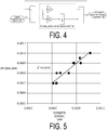
- FIG. 4 illustrates a thermal model of the secondary battery 14.
- a relationship between an external temperature Te of the secondary battery 14 and an internal temperature Ti of the secondary battery 14 is illustrated.
- the secondary battery 14 is modeled as a first-order lag system, and the transfer function T(S) between the external temperature Te and the internal temperature Ti is expressed by Equation (4) below.
- a coefficient K1 is not easily influenced by the type, environment, or the like of the secondary battery 14; and a value calculated in advance for a desired secondary battery 14 can be used as the coefficient K1.
- the CPU 10a applies the integral gain K2 calculated using the Equation (3) to a thermal model such as that described above.
- a thermal model such as that described above.
- the internal temperature Ti of the secondary battery 14 can be estimated from the external temperature Te of the secondary battery 14 detected by the temperature sensor 13.
- temperature-dependent values for example, the element values of the equivalent circuit and the state of function (SOF)
- SOF state of function
- FIG. 5 shows the results of comparing the integral gain K2 estimated according to the present embodiment described above and the integral gain K2 obtained through actual measurement.
- the integral gain estimated according to the embodiment of the present invention is shown on the horizontal axis and the results of actual measurement are shown on the vertical axis.
- FIG. 5 shows that the integral gain estimated according to the present embodiment matches the actual-measurement values with high accuracy, and that a determination coefficient R 2 is 0.9028, demonstrating the actual-measurement values match the estimated values with high accuracy.
- FIG. 6 is a flowchart for explaining an example of the processing executed in FIG. 1 .
- This flowchart is executed when, for example, a new secondary battery 14 is installed in a vehicle (e.g. when a power-on reset is performed on the control unit 10).
- a new secondary battery 14 is installed in a vehicle (e.g. when a power-on reset is performed on the control unit 10).
- step S10 the CPU 10a measures the voltage Vb and the current Ib of the secondary battery 14 that is in a stable state prior to executing the discharging.
- the state can be determined to be stable in cases where, for example, the vehicle is stopped and the current flowing through the load 19 is less than a predetermined threshold value (e.g. a few amperes).
- step S11 the CPU 10a controls the discharge circuit 15 to discharge the secondary battery 14 in a rectangular pulse-like manner.
- a width of the rectangular pulse can be set to, for example, a range of a few milliseconds to a few seconds.
- the discharging may be terminated upon a predetermined number of samplings having been executed or the element values of the equivalent circuit having been calculated, instead of using a preset width of the rectangular pulse.
- step S12 the CPU 10a measures the voltage and the current of the secondary battery 14 while referencing the output from the voltage sensor 11 and the current sensor 12, and stores these measured values as V(t) and I(t) in the RAM 10c as the parameters 10ca.
- step S13 the CPU 10a calculates Z(t) by substituting V(t) and I(t) measured in step S12 into the Equation (1) described above, and stores the resulting value in the RAM 10c as the parameter 10ca.
- step S 14 the CPU 10a determines whether or not the discharging is completed.
- step S14: Yes step S15 is executed; otherwise (step S14: No), step S12 is executed and the same processing as before is repeated.
- step S14: No step S12 is executed and the same processing as before is repeated. For example, when a predetermined period of time has passed, measurement has been executed a predetermined number of times, or the voltage or the current is stable (e.g. when transitioned from a transient state to a stationary state), the determination in step S14 is Yes and step S15 is executed.
- step S 15 the CPU 10a acquires the Z(t) stored in the RAM 10c in step S13, applies the value to the Equation (2), and calculates the values of the Rohm, Rct, and ⁇ using, for example, the least-square method or the like. As a result, values of the Rohm, Rct, and ⁇ that best fit the change in the Z(t) in cases where the secondary battery 14 is discharged in a rectangular pulse, can be obtained.
- step S 17 the CPU 10a corrects the values of the element values Rohm, Rct, and C calculated in step S 15 and step S16 to values at a reference state.
- the reference state is a state where the internal temperature of the secondary battery 14 is 25°C and the SOC of the secondary battery 14 is 100%.
- the correction can be performed through a method in which, for example, a data table or correction formula is stored in advance in the ROM 10b and the correction is performed on the basis of this data table or correction formula. Note that in order to reduce correction errors when executing the correction of the temperature, it is preferable, for example, to use an output value from the temperature sensor 13 for which the stopping time of the vehicle is long (e.g. 12 hours or longer). Alternatively, an estimated value of the internal temperature Ti estimated using an initial value may be used.
- step S18 the CPU 10a substitutes the values of the coefficients A1 to A3 that are stored in the ROM 10b and the element values Rohm, Rct, and C corrected in step S17 into the Equation (3) and obtains a value of the integral gain K2.
- the values of the coefficients A1 to A3 are not affected by the type of the secondary battery 14, the environment in which the secondary battery 14 is used, or the like and, therefore, for example, measured values stored beforehand in the ROM 10b may be used.
- step S19 the CPU 10a applies the integral gain K2 calculated in step S18 to the thermal model illustrated in FIG. 4 .
- the proportional gain K1 is not affected by the type of the secondary battery 14, the environment in which of the secondary battery 14 is used, or the like and, therefore, for example, measured values can stored beforehand in the ROM 10b.
- step S20 the CPU 10a references the output of the temperature sensor 13 and acquires the external temperature Te of the secondary battery 14.
- step S21 the CPU 10a substitutes the external temperature Te measured in step S20 into the thermal model illustrated in FIG. 4 , and estimates the internal temperature Ti of the secondary battery 14.
- the processing of step S20 and step S21 is preferably repeated for a set period of time in accordance with the time constant of the transfer function. That is, measurement over a set period of time is preferable because changes in the internal temperature Ti lag behind changes in the external temperature Te.
- step S22 the CPU 10a calculates the value of the SOF and the like that is temperature-dependent, on the basis of the internal temperature Ti of the secondary battery 14 calculated in step S21. Note that other values may be calculated as well.
- the integral gain K2 of the thermal model of the secondary battery 14 can be calculated using the element values of the equivalent circuit of the secondary battery 14. Additionally, with this integral gain K2, the internal temperature of the secondary battery 14 can be accurately calculated and, therefore, temperature-dependent status values (e.g. SOF) of the secondary battery 14 can be accurately calculated.
- SOF temperature-dependent status values
- the internal temperature Ti can be accurately calculated, regardless of, for example, the size, initial capacity, type, or the like of the secondary battery 14.
- Equation (6) can be used in place of Equation (3).
- K 2 A 1 ⁇ Rohm + A 2 ⁇ Rct 1 + A 3 ⁇ C 1 + A 4 ⁇ Rct 2 + A 5 ⁇ C 2
- Equation (3) an initial full charge capacity SOH_ini, which can be calculated from the element values, is used. More specifically, the initial full charge capacity SHO_ini can be calculated using Equation (7) below.
- f1 (Rohm), f2 (Rct), and f4 (C) represent predetermined functions having Rohm, Rct, and C as variables.
- SOH_ini B 1 ⁇ f 1 Rohm + B 2 ⁇ f 2 Rct + B 3 ⁇ f 3 C
- the integral gain K2 can be obtained by using Equation (8) below that includes the SOH_ini calculated using Equation (7) above.
- K 2 A 0 ⁇ SOH_ini + A 1 ⁇ Rohm + A 2 ⁇ Rct + A 3 ⁇ C 1
- an example of executing the processing shown in FIG. 6 for a case in which the secondary battery 14 is newly installed has been given but, for example, a configuration is possible in which the processing shown in FIG. 6 is re-executed at a predetermined interval, or in cases where errors in the values calculated using the internal temperature Ti increase or the like.
- temperature characteristics change e.g. specific heat declines due an increase of lead sulfate
- the scientific characteristics of the electrode plates of the secondary battery 14 change due to degradation (e.g. lead sulfate increases due to sulfation).
- a thermal model reflecting the state of degradation can be constructed.
- Control unit estimate means, calculation means, determination means, application means, and correction means
Landscapes
- Physics & Mathematics (AREA)
- General Physics & Mathematics (AREA)
- Engineering & Computer Science (AREA)
- Manufacturing & Machinery (AREA)
- Chemical & Material Sciences (AREA)
- Chemical Kinetics & Catalysis (AREA)
- Electrochemistry (AREA)
- General Chemical & Material Sciences (AREA)
- Secondary Cells (AREA)
Abstract
Description
- The present invention relates to a secondary battery internal temperature estimation device and a secondary battery internal temperature estimation method.
- For example, characteristics of secondary batteries such as lead-acid batteries vary with the temperature of the electrolytic solution, the electrode plates, and the like, that is, the internal temperature. As such, there is a need to accurately find the internal temperature in order to accurately detect a state of the secondary battery. Particularly, for a secondary battery installed in a vehicle, the internal temperature changes significantly due to the heat generated by the engine and the like. Therefore, detection of the internal temperature is essential to accurately detect the state of the secondary battery.
- Conventionally, techniques such as those described, for example, in
Patent Document 1 andPatent Document 2 have been used as techniques for finding the internal temperature of a secondary battery. -
- Patent Document 1: Japanese Unexamined Patent Application Publication No.
2001-076769 - Patent Document 2: Japanese Unexamined Patent Application Publication No.
2008-249459 - However, with the techniques described in
Patent Documents Patent Documents - An object of the present invention is to provide a secondary battery internal temperature estimation device and a secondary battery internal temperature estimating method that enable the estimation of the accurate internal temperature of a secondary battery, regardless of the type or state of degradation of the secondary battery.
- To solve the problems described above, a secondary battery internal temperature estimation device that estimates an internal temperature of a secondary battery includes: an estimation means that estimates an internal temperature of a secondary battery on the basis of a relational equation showing a relationship between an external temperature and the internal temperature of the secondary battery; a calculation means that calculates element values of an equivalent circuit of the secondary battery; a determination means that determines a coefficient of the relational equation on the basis of the element values of the equivalent circuit calculated by the calculation means; and
an application means that applies the coefficient obtained by the determination means to the relational equation; wherein the estimation means estimates the internal temperature of the secondary battery on the basis of the relational equation to which the coefficient has been applied by the application means. - According to this configuration, an accurate internal temperature of a secondary battery can be estimated, regardless of the type and state of degradation of the secondary battery.
- Additionally, in the present invention, the equivalent circuit of the secondary battery comprises a solution resistance, a reaction resistance, and an electric double layer capacity; and the determination means determines the coefficient of the relational equation on the basis of one or a plurality of element values of the solution resistance, the reaction resistance, and the electric double layer capacity.
- According to this configuration, an equivalent circuit that includes a plurality of elements is used and, as a result, the internal temperature can be accurately found.
- Additionally, in the present invention, the determination means determines the coefficient of the relational equation by referencing a dischargeable capacity of the secondary battery in a state of full charge.
- According to this configuration, the dischargeable capacity is referenced and, as a result, the internal temperature can be more accurately found.
- Additionally, the present invention further includes a correction means that corrects the element values calculated by the calculation means to values at a reference state of charge and at a reference temperature.
- According to this configuration, the element values are found more accurately by correcting them to a reference state and, as a result, the internal temperature can be found even more accurately.
- Additionally, in the present invention, the estimation means estimates the internal temperature of the secondary battery by using a transfer function of a first-order lag system as the relational equation.
- According to this configuration, the internal temperature can be accurately found using a simple equation.
- Additionally, in the present invention, the determination means determines an integral gain of the transfer function of the first-order lag system on the basis of the element values of the equivalent circuit.
- According to this configuration, the number of coefficients to be calculated is reduced and, as a result, processing can be streamlined.
- Additionally, in the present invention, the calculation means calculates the element values of the equivalent circuit on the basis of a voltage and a current during discharge of the secondary battery.
- According to this configuration, the element values can be simply and accurately calculated on the basis of the voltage and the current during discharge.
- Additionally, a secondary battery internal temperature estimation method for estimating an internal temperature of a secondary battery includes: an estimation step of estimating an internal temperature of a secondary battery on the basis of a relational equation showing a relationship between an external temperature and the internal temperature of the secondary battery; a calculation step of calculating element values of an equivalent circuit of the secondary battery; a determination step of determining a coefficient of the relational equation on the basis of the element values of the equivalent circuit calculated in the calculation step; and an application step of applying the coefficient obtained in the determination step to the relational equation; wherein in the estimation step, the internal temperature of the secondary battery is estimated on the basis of the relational equation to which the coefficient has been applied in the application step.
- According to this method, an accurate internal temperature of a secondary battery can be estimated, regardless of the type and state of degradation of the secondary battery.
- According to the present invention, a secondary battery internal temperature estimation device and a secondary battery internal temperature estimation method can be provided that enable the estimation of the accurate internal temperature of a secondary battery, regardless of the type or state of degradation of the secondary battery.
-
-
FIG. 1 is a drawing illustrating an example of a configuration of a secondary battery internal temperature estimation device according to an embodiment of the present invention. -
FIG. 2 is a block diagram illustrating a detailed example of a configuration of the control unit illustrated inFIG. 1 . -
FIG. 3 is a drawing illustrating an example of an equivalent circuit of a secondary battery. -
FIG. 4 is a drawing illustrating an example of a thermal model of a secondary battery. -
FIG. 5 is a graph showing a relationship between estimated results and actual measurement values. -
FIG. 6 is a flowchart for explaining details of the processing that is executed in the embodiment of the present invention. - Embodiments of the present invention will be described below.
-
FIG. 1 is a drawing illustrating a vehicle power supply system equipped with a secondary battery internal temperature estimation device according to a first embodiment of the present invention. InFIG. 1 , the secondary battery internaltemperature estimation device 1 basically includes acontrol unit 10, avoltage sensor 11, acurrent sensor 12, atemperature sensor 13, and adischarge circuit 15. The secondary battery internaltemperature estimation device 1 is configured to estimate the internal temperature of asecondary battery 14 from an external temperature. Here, thecontrol unit 10 estimates the internal temperature by calculating element values of an equivalent circuit of thesecondary battery 14 while referencing output from thevoltage sensor 11, thecurrent sensor 12, and thetemperature sensor 13; finding a coefficient of an equation by which temperature is estimated on the basis of the element values; and substituting the external temperature detected by thetemperature sensor 13 into this equation. Thevoltage sensor 11 detects the terminal voltage of thesecondary battery 14 and sends the result to thecontrol unit 10. Thecurrent sensor 12 detects the current flowing to thesecondary battery 14 and sends the result to thecontrol unit 10. Thetemperature sensor 13 detects the external temperature of thesecondary battery 14 itself or the ambient temperature therearound and sends the result to thecontrol unit 10. Thedischarge circuit 15, which is constituted of, for example, a semiconductor switch, a resistance element, and the like connected in series, discharges thesecondary battery 14 through on/off control of the semiconductor switch performed by thecontrol unit 10. Note that, in the present specification, the term "external temperature" refers to the temperature of the environmental in which thesecondary battery 14 is disposed, and the term "internal temperature" refers to the temperature inside thesecondary battery 14 constituted of electrolytic solution and electrode plates. - The
secondary battery 14, which is constituted of, for example, a lead-acid battery, a nickel-cadmium battery, a nickel-metal hydride battery, a lithium-ion battery, or the like, is charged by analternator 16. In addition, thesecondary battery 14 drives astarter motor 18 to start an engine and supplies electric power to aload 19. Thealternator 16 is driven by theengine 17 to generate AC power that is converted to DC power by a rectifier circuit; thesecondary battery 14 is then charged with the DC power. - The
engine 17 is a reciprocating engine such as a petrol engine or a diesel engine, or a rotary engine, for example. Theengine 17 is started by thestarter motor 18 and drives drive wheels via a transmission to supply propulsive power to the vehicle. Theengine 17 also drives thealternator 16 to generate electric power. Thestarter motor 18 is a DC motor, for example, and generates a rotational force using electric power supplied from thesecondary battery 14 to start theengine 17. Examples of theload 19 include an electric power steering motor, a defogger, an ignition coil, a car audio system, and a car navigation system, and run on electric power from thesecondary battery 14. -
FIG. 2 is a block diagram illustrating a detailed example of a configuration of thecontrol unit 10 illustrated inFIG. 1 . As illustrated inFIG. 2 , thecontrol unit 10 includes a central processing unit (CPU) 10a, a read-only memory (ROM) 10b, a random access memory (RAM) 10c, a communication unit 10d, and an interface (I/F) 10e. Here, the CPU 10a controls components according to a program 10ba stored in the ROM 10b. The ROM 10b, which is, for example, a semiconductor memory, stores the program 10ba and the like. The RAM 10c, which is, for example, a semiconductor memory, stores parameters 10ca such as data generated when the program ba is executed and tables and mathematical expressions described later. The communication unit 10d performs communication with a higher-level device, namely, an electronic control unit (ECU), and reports detected information to the higher-level device. The I/F 10e converts signals sent from thevoltage sensor 11, thecurrent sensor 12, and thetemperature sensor 13 to digital signals and imports the resulting signals, and furthermore supplies a driving current to thedischarge circuit 15 to control thedischarge circuit 15. - Next, the operation of the embodiment of the present invention will be described. In the embodiment of the present invention, for example, at a timing when input/output current to and from the
secondary battery 14 is small such as when the vehicle is stopped, the CPU 10a of thecontrol unit 10 references the output of thevoltage sensor 11 and thecurrent sensor 12, measures voltage Vb and current Ib of thesecondary battery 14, and stores these measurement values as parameters 10ca in the RAM 10c. - Next, the CPU 10a controls the
discharge circuit 15 to discharge thesecondary battery 14 at a predetermined current (e.g. from a few amperes to a few dozen amperes). Note that this discharging is executed, for example, using a square wave or a step wave. Additionally, the discharging time can be set to, for example, from a few dozen milliseconds, to a few seconds. - When the discharging by the
discharge circuit 15 begins, the CPU 10a samples the output from thevoltage sensor 11 and thecurrent sensor 12 at a predetermined period (e.g. a period of a few milliseconds to a few dozen milliseconds), and stores the sampled values as V(t) and I(t) in the RAM 10c as the parameters 10ca. Note that t represents time and is set to '0' at the timing when the sampling is begun; and is incremented with subsequent sampling. The CPU 10a substitutes the obtained V(t) and I(t) into Equation (1) below, calculates an impedance Z(t) of thesecondary battery 14, and stores the impedance Z(t) in the RAM 10c as the parameter 10ca.
- Additionally, on the basis of Equation (2) below, the CPU 10a uses the Z(t) obtained through the measurement and calculates the element values of the equivalent circuit, namely, Rohm, Rct, and C, using the least-square method or the like.

- Next, the CPU 10a corrects the obtained Rohm, Rct, and C to a Rohm, Rct, and C at a reference state. Here, the reference state is a state where the state of charge (SOC) of the
secondary battery 14 is 100% and the internal temperature Ti of thesecondary battery 14 is 25°C. In cases where the SOC and the temperature deviate from the reference state, the element values are corrected so as to match the reference state. - Next, the CPU 10a substitutes the Rohm, Rct, and C that have been corrected to the reference state into Equation (3) below, and calculates an integral gain K2.

- Here, coefficients A1 to A3 are for associating the element values of the equivalent circuit of the
secondary battery 14 with the integral gain K2, and these values do not change with the type of thesecondary battery 14, the type of a vehicle in which thesecondary battery 14 is used, the environment in which thesecondary battery 14 is used, or the like. These coefficients A1 to A3 may be measured in advance and stored in the ROM 10b. - Next, the CPU 10a applies the integral gain K2 calculated using the Equation (3) to a thermal model of the
secondary battery 14 illustrated inFIG. 4 . Here,FIG. 4 illustrates a thermal model of thesecondary battery 14. In this example, a relationship between an external temperature Te of thesecondary battery 14 and an internal temperature Ti of thesecondary battery 14 is illustrated. In this model, thesecondary battery 14 is modeled as a first-order lag system, and the transfer function T(S) between the external temperature Te and the internal temperature Ti is expressed by Equation (4) below. Note that a coefficient K1 is not easily influenced by the type, environment, or the like of thesecondary battery 14; and a value calculated in advance for a desiredsecondary battery 14 can be used as the coefficient K1.
- The CPU 10a applies the integral gain K2 calculated using the Equation (3) to a thermal model such as that described above. By using such a thermal model, the internal temperature Ti of the
secondary battery 14 can be estimated from the external temperature Te of thesecondary battery 14 detected by thetemperature sensor 13. By using the internal temperature Ti thus calculated, temperature-dependent values, for example, the element values of the equivalent circuit and the state of function (SOF), can be accurately calculated and, as a result, the state of thesecondary battery 14 can be detected with high accuracy. -
FIG. 5 shows the results of comparing the integral gain K2 estimated according to the present embodiment described above and the integral gain K2 obtained through actual measurement. InFIG. 5 , the integral gain estimated according to the embodiment of the present invention is shown on the horizontal axis and the results of actual measurement are shown on the vertical axis.FIG. 5 shows that the integral gain estimated according to the present embodiment matches the actual-measurement values with high accuracy, and that a determination coefficient R2 is 0.9028, demonstrating the actual-measurement values match the estimated values with high accuracy. - Next, detailed operations of the embodiment of the present invention will be described while referring to
FIG. 6. FIG. 6 is a flowchart for explaining an example of the processing executed inFIG. 1 . This flowchart is executed when, for example, a newsecondary battery 14 is installed in a vehicle (e.g. when a power-on reset is performed on the control unit 10). Once the flowchart shown inFIG. 6 starts, the following steps are executed. - In step S10, the CPU 10a measures the voltage Vb and the current Ib of the
secondary battery 14 that is in a stable state prior to executing the discharging. Note that, the state can be determined to be stable in cases where, for example, the vehicle is stopped and the current flowing through theload 19 is less than a predetermined threshold value (e.g. a few amperes). - In step S11, the CPU 10a controls the
discharge circuit 15 to discharge thesecondary battery 14 in a rectangular pulse-like manner. Note that a width of the rectangular pulse can be set to, for example, a range of a few milliseconds to a few seconds. The discharging may be terminated upon a predetermined number of samplings having been executed or the element values of the equivalent circuit having been calculated, instead of using a preset width of the rectangular pulse. - In step S12, the CPU 10a measures the voltage and the current of the
secondary battery 14 while referencing the output from thevoltage sensor 11 and thecurrent sensor 12, and stores these measured values as V(t) and I(t) in the RAM 10c as the parameters 10ca. - In step S13, the CPU 10a calculates Z(t) by substituting V(t) and I(t) measured in step S12 into the Equation (1) described above, and stores the resulting value in the RAM 10c as the parameter 10ca.
- In
step S 14, the CPU 10a determines whether or not the discharging is completed. When it is determined that the discharging is completed (step S14: Yes), step S15 is executed; otherwise (step S14: No), step S12 is executed and the same processing as before is repeated. For example, when a predetermined period of time has passed, measurement has been executed a predetermined number of times, or the voltage or the current is stable (e.g. when transitioned from a transient state to a stationary state), the determination in step S14 is Yes and step S15 is executed. - In
step S 15, the CPU 10a acquires the Z(t) stored in the RAM 10c in step S13, applies the value to the Equation (2), and calculates the values of the Rohm, Rct, and τ using, for example, the least-square method or the like. As a result, values of the Rohm, Rct, and τ that best fit the change in the Z(t) in cases where thesecondary battery 14 is discharged in a rectangular pulse, can be obtained. - In step S16, the CPU 10a substitutes the τ and the Rct calculated in step S15 into C = τ / Rct and obtains a value for the electric double layer capacity C.
- In
step S 17, the CPU 10a corrects the values of the element values Rohm, Rct, and C calculated in step S 15 and step S16 to values at a reference state. The reference state is a state where the internal temperature of thesecondary battery 14 is 25°C and the SOC of thesecondary battery 14 is 100%. The correction can be performed through a method in which, for example, a data table or correction formula is stored in advance in the ROM 10b and the correction is performed on the basis of this data table or correction formula. Note that in order to reduce correction errors when executing the correction of the temperature, it is preferable, for example, to use an output value from thetemperature sensor 13 for which the stopping time of the vehicle is long (e.g. 12 hours or longer). Alternatively, an estimated value of the internal temperature Ti estimated using an initial value may be used. - In step S18, the CPU 10a substitutes the values of the coefficients A1 to A3 that are stored in the ROM 10b and the element values Rohm, Rct, and C corrected in step S17 into the Equation (3) and obtains a value of the integral gain K2. Note that the values of the coefficients A1 to A3 are not affected by the type of the
secondary battery 14, the environment in which thesecondary battery 14 is used, or the like and, therefore, for example, measured values stored beforehand in the ROM 10b may be used. - In step S19, the CPU 10a applies the integral gain K2 calculated in step S18 to the thermal model illustrated in
FIG. 4 . Note that the proportional gain K1 is not affected by the type of thesecondary battery 14, the environment in which of thesecondary battery 14 is used, or the like and, therefore, for example, measured values can stored beforehand in the ROM 10b. - In step S20, the CPU 10a references the output of the
temperature sensor 13 and acquires the external temperature Te of thesecondary battery 14. - In step S21, the CPU 10a substitutes the external temperature Te measured in step S20 into the thermal model illustrated in
FIG. 4 , and estimates the internal temperature Ti of thesecondary battery 14. Note that the processing of step S20 and step S21 is preferably repeated for a set period of time in accordance with the time constant of the transfer function. That is, measurement over a set period of time is preferable because changes in the internal temperature Ti lag behind changes in the external temperature Te. - In step S22, the CPU 10a calculates the value of the SOF and the like that is temperature-dependent, on the basis of the internal temperature Ti of the
secondary battery 14 calculated in step S21. Note that other values may be calculated as well. - As described above, according to the flowchart shown in
FIG. 6 , the integral gain K2 of the thermal model of thesecondary battery 14 can be calculated using the element values of the equivalent circuit of thesecondary battery 14. Additionally, with this integral gain K2, the internal temperature of thesecondary battery 14 can be accurately calculated and, therefore, temperature-dependent status values (e.g. SOF) of thesecondary battery 14 can be accurately calculated. - Additionally, by calculating the integral gain K2 from the equivalent circuit of the
secondary battery 14, the internal temperature Ti can be accurately calculated, regardless of, for example, the size, initial capacity, type, or the like of thesecondary battery 14. - It is needless to say that the embodiment described above is only an example and the present invention is not limited to the embodiment as described above. For example, in the embodiment described above, the equivalent circuit illustrated in
FIG. 3 is used, but configurations are possible in which different equivalent circuits are used. Specifically, a configuration is possible in which an equivalent circuit is used that has two or more reaction resistances and electric double layer capacities. Note that in cases of using an equivalent circuit having two reaction resistances and electric double layer capacities, the two reaction resistances are referred to as Rtc1 and Rtc2 and the two electric double layer capacities are referred to as C1 and C2; and, in such a case, Equation (5) below is used in place of Equation (2).
- Note that τ1 and τ2 are defined as follows:


- Additionally, Equation (6) below can be used in place of Equation (3).

- Additionally, in the embodiment described above, only the element values of the equivalent circuit is included in Equation (3) for calculating the integral gain K2 but, for example, a configuration is possible in which an initial full charge capacity SOH_ini, which can be calculated from the element values, is used. More specifically, the initial full charge capacity SHO_ini can be calculated using Equation (7) below. Here, f1 (Rohm), f2 (Rct), and f4 (C) represent predetermined functions having Rohm, Rct, and C as variables.

- The integral gain K2 can be obtained by using Equation (8) below that includes the SOH_ini calculated using Equation (7) above.

- Additionally, a configuration is possible in which an equation is used in which A0 × SOH_ini is added to the right side of Equation (6) above.
- Additionally, in the embodiment described above, all of the solution resistance Rohm, the reaction resistance Rct, and the electric double layer capacity C constituting the equivalent circuit are used, but configurations are possible in which one of these is used or a combination of any two of these are used.
- Additionally, in the embodiment described above, an example of executing the processing shown in
FIG. 6 for a case in which thesecondary battery 14 is newly installed has been given but, for example, a configuration is possible in which the processing shown inFIG. 6 is re-executed at a predetermined interval, or in cases where errors in the values calculated using the internal temperature Ti increase or the like. For example, temperature characteristics change (e.g. specific heat declines due an increase of lead sulfate) due to the fact that the scientific characteristics of the electrode plates of thesecondary battery 14 change due to degradation (e.g. lead sulfate increases due to sulfation). As such, in order to reproduce the characteristics that change with degradation, by executing the processing shown inFIG. 6 every one month for example, a thermal model reflecting the state of degradation can be constructed. - 1 Secondary battery internal
temperature estimation device 10 Control unit (estimation means, calculation means, determination means, application means, and correction means) - 10a
- CPU
- 10b
- ROM
- 10c
- RAM
- 10d
- Display
- 10e
- I/F
- 11
- Voltage sensor
- 12
- Current sensor
- 13
- Temperature sensor
- 14
- Secondary battery
- 15
- Discharge circuit
- 16
- Alternator
- 17
- Engine
- 18
- Starter motor
- 19
- Load
Claims (8)
- A secondary battery internal temperature estimation device that estimates an internal temperature of a secondary battery, the device comprising:an estimation means that estimates an internal temperature of a secondary battery on the basis of a relational equation showing a relationship between an external temperature and the internal temperature of the secondary battery;a calculation means that calculates element values of an equivalent circuit of the secondary battery;a determination means that determines a coefficient of the relational equation on the basis of the element values of the equivalent circuit calculated by the calculation means; andan application means that applies the coefficient obtained by the determination means to the relational equation; whereinthe estimation means estimates the internal temperature of the secondary battery on the basis of the relational equation to which the coefficient has been applied by the application means.
- The secondary battery internal temperature estimation device according to claim 1, wherein:the equivalent circuit of the secondary battery comprises a solution resistance, a reaction resistance, and an electric double layer capacity; andthe determination means determines the coefficient of the relational equation on the basis of one or a plurality of element values of the solution resistance, the reaction resistance, and the electric double layer capacity.
- The secondary battery internal temperature estimation device according to claim 1 or 2, wherein:the determination means determines the coefficient of the relational equation by referencing a dischargeable capacity of the secondary battery in a state of full charge.
- The secondary battery internal temperature estimation device according to any one of claims 1 to 3, further comprising:a correction means that corrects the element values calculated by the calculation means to values at a reference state of charge and at a reference temperature.
- The secondary battery internal temperature estimation device according to any one of claims 1 to 4, wherein:the estimation means estimates the internal temperature of the secondary battery by using a transfer function of a first-order lag system as the relational equation.
- The secondary battery internal temperature estimation device according to claim 5, wherein:the determination means determines an integral gain of the transfer function of the first-order lag system on the basis of the element values of the equivalent circuit.
- The secondary battery internal temperature estimation device according to any one of claims 1 to 6, wherein:the calculation means calculates the element values of the equivalent circuit on the basis of a voltage and a current during discharge of the secondary battery.
- A secondary battery internal temperature estimation method for estimating an internal temperature of a secondary battery, the method comprising:an estimation step of estimating an internal temperature of a secondary battery on the basis of a relational equation showing a relationship between an external temperature and the internal temperature of the secondary battery;a calculation step of calculating element values of an equivalent circuit of the secondary battery;a determination step of determining a coefficient of the relational equation on the basis of the element values of the equivalent circuit calculated in the calculation step; andan application step of applying the coefficient obtained in the determination step to the relational equation; whereinin the estimation step, the internal temperature of the secondary battery is estimated on the basis of the relational equation to which the coefficient has been applied in the application step.
Applications Claiming Priority (2)
| Application Number | Priority Date | Filing Date | Title |
|---|---|---|---|
| JP2014059252A JP6200359B2 (en) | 2014-03-20 | 2014-03-20 | Secondary battery internal temperature estimation device and secondary battery internal temperature estimation method |
| PCT/JP2015/057483 WO2015141580A1 (en) | 2014-03-20 | 2015-03-13 | Secondary battery internal temperature estimation device and secondary battery internal temperature estimation method |
Publications (3)
| Publication Number | Publication Date |
|---|---|
| EP3107146A1 true EP3107146A1 (en) | 2016-12-21 |
| EP3107146A4 EP3107146A4 (en) | 2017-11-01 |
| EP3107146B1 EP3107146B1 (en) | 2019-01-23 |
Family
ID=54144549
Family Applications (1)
| Application Number | Title | Priority Date | Filing Date |
|---|---|---|---|
| EP15765576.2A Active EP3107146B1 (en) | 2014-03-20 | 2015-03-13 | Secondary battery internal temperature estimation device and secondary battery internal temperature estimation method |
Country Status (5)
| Country | Link |
|---|---|
| US (1) | US10396407B2 (en) |
| EP (1) | EP3107146B1 (en) |
| JP (1) | JP6200359B2 (en) |
| CN (1) | CN106104907B (en) |
| WO (1) | WO2015141580A1 (en) |
Cited By (2)
| Publication number | Priority date | Publication date | Assignee | Title |
|---|---|---|---|---|
| CN110495046A (en) * | 2017-11-07 | 2019-11-22 | 株式会社Lg化学 | Apparatus and method for estimating the temperature of a battery |
| EP4503259A4 (en) * | 2022-03-31 | 2026-04-15 | Vehicle Energy Japan Inc | BATTERY CONTROL DEVICE |
Families Citing this family (12)
| Publication number | Priority date | Publication date | Assignee | Title |
|---|---|---|---|---|
| WO2014185163A1 (en) * | 2013-05-16 | 2014-11-20 | 日本電気株式会社 | Cell state-maintaining device, cell state management system, cell, method for maintaining cell state, and program |
| JP6928228B2 (en) * | 2016-11-25 | 2021-09-01 | ミツミ電機株式会社 | Battery monitoring circuit |
| JP6826935B2 (en) * | 2017-03-30 | 2021-02-10 | 古河電気工業株式会社 | Secondary battery internal temperature estimation device and secondary battery internal temperature estimation method |
| DE102017209182A1 (en) * | 2017-05-31 | 2018-12-06 | Bayerische Motoren Werke Aktiengesellschaft | Method and device for determining an operating temperature, operating method for a battery cell, control unit for a battery cell and working device |
| CN109738821A (en) * | 2017-10-31 | 2019-05-10 | 华晨汽车集团控股有限公司 | A method for obtaining the acid temperature of a virtual battery |
| WO2019131740A1 (en) * | 2017-12-27 | 2019-07-04 | 古河電気工業株式会社 | Rechargeable battery temperature estimation device and rechargeable battery temperature estimation method |
| CN109520638A (en) * | 2018-10-15 | 2019-03-26 | 武汉科技大学 | Mean temperature determines method and system in real time inside cylindrical battery |
| JP7233270B2 (en) * | 2019-03-22 | 2023-03-06 | 古河電気工業株式会社 | Rechargeable battery temperature estimation device and rechargeable battery temperature estimation method |
| CN112578298B (en) * | 2019-09-29 | 2022-03-15 | 比亚迪股份有限公司 | Battery temperature estimation method, device, electronic equipment and storage medium |
| CN112964991B (en) * | 2019-11-28 | 2022-07-15 | 比亚迪股份有限公司 | Method for processing temperature information in battery, computer device and storage medium |
| DE102020003887B3 (en) | 2020-06-29 | 2021-10-21 | Daimler Ag | Method for determining the respective temperature of a plurality of battery cells of a vehicle battery by extrapolating a measured temperature; Control device and vehicle battery |
| JP7468462B2 (en) * | 2021-06-11 | 2024-04-16 | トヨタ自動車株式会社 | Battery System |
Family Cites Families (12)
| Publication number | Priority date | Publication date | Assignee | Title |
|---|---|---|---|---|
| JP4383596B2 (en) | 1999-09-06 | 2009-12-16 | トヨタ自動車株式会社 | Battery internal temperature detection device |
| JP4327692B2 (en) * | 2004-09-30 | 2009-09-09 | トヨタ自動車株式会社 | Secondary battery charge / discharge controller |
| JP5008863B2 (en) * | 2005-11-30 | 2012-08-22 | プライムアースEvエナジー株式会社 | Secondary battery control device, secondary battery deterioration determination method using secondary battery temperature estimation method |
| JP2008249459A (en) | 2007-03-30 | 2008-10-16 | Mazda Motor Corp | Battery temperature estimation device |
| JP2010135075A (en) * | 2008-12-02 | 2010-06-17 | Calsonic Kansei Corp | Method and device for estimating temperature of battery pack |
| JP5293820B2 (en) * | 2009-07-08 | 2013-09-18 | トヨタ自動車株式会社 | Secondary battery temperature increasing device and vehicle equipped with the same |
| WO2011045853A1 (en) * | 2009-10-14 | 2011-04-21 | 株式会社 日立製作所 | Battery control device and motor drive system |
| EP2551687B1 (en) * | 2010-03-23 | 2020-07-15 | Furukawa Electric Co., Ltd. | Device for estimating internal state of battery, and method for estimating internal state of battery |
| JP5379820B2 (en) * | 2011-03-16 | 2013-12-25 | 古河電気工業株式会社 | Secondary battery temperature estimation device and secondary battery temperature estimation method |
| KR101609076B1 (en) * | 2011-08-01 | 2016-04-04 | 알프스 그린 디바이스 가부시키가이샤 | Battery device temperature measurement method |
| JP2013118724A (en) * | 2011-12-01 | 2013-06-13 | Toyota Motor Corp | Control device and control method |
| JP6040684B2 (en) * | 2012-09-28 | 2016-12-07 | 富士通株式会社 | Secondary battery state evaluation device, secondary battery state evaluation method, and secondary battery state evaluation program |
-
2014
- 2014-03-20 JP JP2014059252A patent/JP6200359B2/en active Active
-
2015
- 2015-03-13 CN CN201580013438.6A patent/CN106104907B/en active Active
- 2015-03-13 WO PCT/JP2015/057483 patent/WO2015141580A1/en not_active Ceased
- 2015-03-13 EP EP15765576.2A patent/EP3107146B1/en active Active
-
2016
- 2016-09-16 US US15/268,512 patent/US10396407B2/en active Active
Cited By (3)
| Publication number | Priority date | Publication date | Assignee | Title |
|---|---|---|---|---|
| CN110495046A (en) * | 2017-11-07 | 2019-11-22 | 株式会社Lg化学 | Apparatus and method for estimating the temperature of a battery |
| US11552343B2 (en) | 2017-11-07 | 2023-01-10 | Lg Energy Solution, Ltd. | Apparatus and method for estimating temperature of battery |
| EP4503259A4 (en) * | 2022-03-31 | 2026-04-15 | Vehicle Energy Japan Inc | BATTERY CONTROL DEVICE |
Also Published As
| Publication number | Publication date |
|---|---|
| US10396407B2 (en) | 2019-08-27 |
| WO2015141580A1 (en) | 2015-09-24 |
| JP6200359B2 (en) | 2017-09-20 |
| JP2015185284A (en) | 2015-10-22 |
| US20170012327A1 (en) | 2017-01-12 |
| EP3107146A4 (en) | 2017-11-01 |
| EP3107146B1 (en) | 2019-01-23 |
| CN106104907A (en) | 2016-11-09 |
| CN106104907B (en) | 2019-06-04 |
Similar Documents
| Publication | Publication Date | Title |
|---|---|---|
| EP3107146B1 (en) | Secondary battery internal temperature estimation device and secondary battery internal temperature estimation method | |
| US10656210B2 (en) | Secondary battery state detection device and secondary battery state detection method | |
| US10393814B2 (en) | Secondary battery state detection device and secondary battery state detection method | |
| US11163010B2 (en) | Secondary battery deterioration estimation device and secondary battery deterioration estimation method | |
| US10393820B2 (en) | Secondary battery state detecting device and secondary battery state detecting method | |
| JP5051661B2 (en) | Method and apparatus for estimating SOC value of secondary battery, and degradation determination method and apparatus | |
| EP3113277B1 (en) | Secondary battery state detection device and secondary battery state detection method | |
| US20180001782A1 (en) | Method and device for detecting soc of battery | |
| US11095130B2 (en) | Power storage apparatus for estimating an open-circuit voltage | |
| US9897657B2 (en) | Method and apparatuses for determining a state of charge | |
| US10422836B2 (en) | Device and method for estimating state-of-health of battery | |
| JP6440377B2 (en) | Secondary battery state detection device and secondary battery state detection method | |
| EP2778701B1 (en) | Secondary battery state detection device and secondary battery state detection method | |
| JP5653881B2 (en) | Secondary battery state detection device and secondary battery state detection method | |
| JPWO2008026477A1 (en) | Method and apparatus for estimating SOC value of secondary battery, and degradation determination method and apparatus | |
| JP2012189373A (en) | Secondary battery condition detection device and secondary battery condition detection method | |
| WO2017179175A1 (en) | Estimation device, estimation program, and charging control device | |
| JP6498920B2 (en) | Secondary battery state detection device and secondary battery state detection method | |
| JP6979896B2 (en) | Rechargeable battery status detector and rechargeable battery status detection method | |
| EP3923396B1 (en) | Chargeable battery state detection device and chargeable battery state detection method | |
| US11189863B2 (en) | Power storage apparatus | |
| WO2024117022A1 (en) | Estimating device, electricity storage device, estimating method, and estimating program |
Legal Events
| Date | Code | Title | Description |
|---|---|---|---|
| STAA | Information on the status of an ep patent application or granted ep patent |
Free format text: STATUS: THE INTERNATIONAL PUBLICATION HAS BEEN MADE |
|
| PUAI | Public reference made under article 153(3) epc to a published international application that has entered the european phase |
Free format text: ORIGINAL CODE: 0009012 |
|
| STAA | Information on the status of an ep patent application or granted ep patent |
Free format text: STATUS: REQUEST FOR EXAMINATION WAS MADE |
|
| 17P | Request for examination filed |
Effective date: 20160914 |
|
| AK | Designated contracting states |
Kind code of ref document: A1 Designated state(s): AL AT BE BG CH CY CZ DE DK EE ES FI FR GB GR HR HU IE IS IT LI LT LU LV MC MK MT NL NO PL PT RO RS SE SI SK SM TR |
|
| AX | Request for extension of the european patent |
Extension state: BA ME |
|
| DAV | Request for validation of the european patent (deleted) | ||
| DAX | Request for extension of the european patent (deleted) | ||
| A4 | Supplementary search report drawn up and despatched |
Effective date: 20171005 |
|
| RIC1 | Information provided on ipc code assigned before grant |
Ipc: G01K 7/42 20060101ALI20170926BHEP Ipc: H02J 7/10 20060101ALI20170926BHEP Ipc: G01R 31/36 20060101ALI20170926BHEP Ipc: H02J 7/00 20060101ALI20170926BHEP Ipc: H01M 10/48 20060101AFI20170926BHEP |
|
| RIC1 | Information provided on ipc code assigned before grant |
Ipc: H01M 10/48 20060101AFI20180614BHEP |
|
| GRAP | Despatch of communication of intention to grant a patent |
Free format text: ORIGINAL CODE: EPIDOSNIGR1 |
|
| STAA | Information on the status of an ep patent application or granted ep patent |
Free format text: STATUS: GRANT OF PATENT IS INTENDED |
|
| INTG | Intention to grant announced |
Effective date: 20180802 |
|
| GRAS | Grant fee paid |
Free format text: ORIGINAL CODE: EPIDOSNIGR3 |
|
| GRAA | (expected) grant |
Free format text: ORIGINAL CODE: 0009210 |
|
| STAA | Information on the status of an ep patent application or granted ep patent |
Free format text: STATUS: THE PATENT HAS BEEN GRANTED |
|
| AK | Designated contracting states |
Kind code of ref document: B1 Designated state(s): AL AT BE BG CH CY CZ DE DK EE ES FI FR GB GR HR HU IE IS IT LI LT LU LV MC MK MT NL NO PL PT RO RS SE SI SK SM TR |
|
| REG | Reference to a national code |
Ref country code: GB Ref legal event code: FG4D |
|
| REG | Reference to a national code |
Ref country code: CH Ref legal event code: EP |
|
| REG | Reference to a national code |
Ref country code: AT Ref legal event code: REF Ref document number: 1092180 Country of ref document: AT Kind code of ref document: T Effective date: 20190215 |
|
| REG | Reference to a national code |
Ref country code: IE Ref legal event code: FG4D |
|
| REG | Reference to a national code |
Ref country code: DE Ref legal event code: R096 Ref document number: 602015023700 Country of ref document: DE |
|
| REG | Reference to a national code |
Ref country code: NL Ref legal event code: MP Effective date: 20190123 |
|
| PG25 | Lapsed in a contracting state [announced via postgrant information from national office to epo] |
Ref country code: NL Free format text: LAPSE BECAUSE OF FAILURE TO SUBMIT A TRANSLATION OF THE DESCRIPTION OR TO PAY THE FEE WITHIN THE PRESCRIBED TIME-LIMIT Effective date: 20190123 |
|
| PG25 | Lapsed in a contracting state [announced via postgrant information from national office to epo] |
Ref country code: FI Free format text: LAPSE BECAUSE OF FAILURE TO SUBMIT A TRANSLATION OF THE DESCRIPTION OR TO PAY THE FEE WITHIN THE PRESCRIBED TIME-LIMIT Effective date: 20190123 Ref country code: LT Free format text: LAPSE BECAUSE OF FAILURE TO SUBMIT A TRANSLATION OF THE DESCRIPTION OR TO PAY THE FEE WITHIN THE PRESCRIBED TIME-LIMIT Effective date: 20190123 Ref country code: SE Free format text: LAPSE BECAUSE OF FAILURE TO SUBMIT A TRANSLATION OF THE DESCRIPTION OR TO PAY THE FEE WITHIN THE PRESCRIBED TIME-LIMIT Effective date: 20190123 Ref country code: NO Free format text: LAPSE BECAUSE OF FAILURE TO SUBMIT A TRANSLATION OF THE DESCRIPTION OR TO PAY THE FEE WITHIN THE PRESCRIBED TIME-LIMIT Effective date: 20190423 Ref country code: PT Free format text: LAPSE BECAUSE OF FAILURE TO SUBMIT A TRANSLATION OF THE DESCRIPTION OR TO PAY THE FEE WITHIN THE PRESCRIBED TIME-LIMIT Effective date: 20190523 Ref country code: ES Free format text: LAPSE BECAUSE OF FAILURE TO SUBMIT A TRANSLATION OF THE DESCRIPTION OR TO PAY THE FEE WITHIN THE PRESCRIBED TIME-LIMIT Effective date: 20190123 Ref country code: PL Free format text: LAPSE BECAUSE OF FAILURE TO SUBMIT A TRANSLATION OF THE DESCRIPTION OR TO PAY THE FEE WITHIN THE PRESCRIBED TIME-LIMIT Effective date: 20190123 |
|
| REG | Reference to a national code |
Ref country code: AT Ref legal event code: MK05 Ref document number: 1092180 Country of ref document: AT Kind code of ref document: T Effective date: 20190123 |
|
| PG25 | Lapsed in a contracting state [announced via postgrant information from national office to epo] |
Ref country code: HR Free format text: LAPSE BECAUSE OF FAILURE TO SUBMIT A TRANSLATION OF THE DESCRIPTION OR TO PAY THE FEE WITHIN THE PRESCRIBED TIME-LIMIT Effective date: 20190123 Ref country code: RS Free format text: LAPSE BECAUSE OF FAILURE TO SUBMIT A TRANSLATION OF THE DESCRIPTION OR TO PAY THE FEE WITHIN THE PRESCRIBED TIME-LIMIT Effective date: 20190123 Ref country code: GR Free format text: LAPSE BECAUSE OF FAILURE TO SUBMIT A TRANSLATION OF THE DESCRIPTION OR TO PAY THE FEE WITHIN THE PRESCRIBED TIME-LIMIT Effective date: 20190424 Ref country code: LV Free format text: LAPSE BECAUSE OF FAILURE TO SUBMIT A TRANSLATION OF THE DESCRIPTION OR TO PAY THE FEE WITHIN THE PRESCRIBED TIME-LIMIT Effective date: 20190123 Ref country code: IS Free format text: LAPSE BECAUSE OF FAILURE TO SUBMIT A TRANSLATION OF THE DESCRIPTION OR TO PAY THE FEE WITHIN THE PRESCRIBED TIME-LIMIT Effective date: 20190523 Ref country code: BG Free format text: LAPSE BECAUSE OF FAILURE TO SUBMIT A TRANSLATION OF THE DESCRIPTION OR TO PAY THE FEE WITHIN THE PRESCRIBED TIME-LIMIT Effective date: 20190423 |
|
| REG | Reference to a national code |
Ref country code: DE Ref legal event code: R097 Ref document number: 602015023700 Country of ref document: DE |
|
| PG25 | Lapsed in a contracting state [announced via postgrant information from national office to epo] |
Ref country code: EE Free format text: LAPSE BECAUSE OF FAILURE TO SUBMIT A TRANSLATION OF THE DESCRIPTION OR TO PAY THE FEE WITHIN THE PRESCRIBED TIME-LIMIT Effective date: 20190123 Ref country code: RO Free format text: LAPSE BECAUSE OF FAILURE TO SUBMIT A TRANSLATION OF THE DESCRIPTION OR TO PAY THE FEE WITHIN THE PRESCRIBED TIME-LIMIT Effective date: 20190123 Ref country code: CZ Free format text: LAPSE BECAUSE OF FAILURE TO SUBMIT A TRANSLATION OF THE DESCRIPTION OR TO PAY THE FEE WITHIN THE PRESCRIBED TIME-LIMIT Effective date: 20190123 Ref country code: IT Free format text: LAPSE BECAUSE OF FAILURE TO SUBMIT A TRANSLATION OF THE DESCRIPTION OR TO PAY THE FEE WITHIN THE PRESCRIBED TIME-LIMIT Effective date: 20190123 Ref country code: SK Free format text: LAPSE BECAUSE OF FAILURE TO SUBMIT A TRANSLATION OF THE DESCRIPTION OR TO PAY THE FEE WITHIN THE PRESCRIBED TIME-LIMIT Effective date: 20190123 Ref country code: DK Free format text: LAPSE BECAUSE OF FAILURE TO SUBMIT A TRANSLATION OF THE DESCRIPTION OR TO PAY THE FEE WITHIN THE PRESCRIBED TIME-LIMIT Effective date: 20190123 Ref country code: MC Free format text: LAPSE BECAUSE OF FAILURE TO SUBMIT A TRANSLATION OF THE DESCRIPTION OR TO PAY THE FEE WITHIN THE PRESCRIBED TIME-LIMIT Effective date: 20190123 Ref country code: AL Free format text: LAPSE BECAUSE OF FAILURE TO SUBMIT A TRANSLATION OF THE DESCRIPTION OR TO PAY THE FEE WITHIN THE PRESCRIBED TIME-LIMIT Effective date: 20190123 |
|
| REG | Reference to a national code |
Ref country code: CH Ref legal event code: PL |
|
| PG25 | Lapsed in a contracting state [announced via postgrant information from national office to epo] |
Ref country code: LU Free format text: LAPSE BECAUSE OF NON-PAYMENT OF DUE FEES Effective date: 20190313 Ref country code: SM Free format text: LAPSE BECAUSE OF FAILURE TO SUBMIT A TRANSLATION OF THE DESCRIPTION OR TO PAY THE FEE WITHIN THE PRESCRIBED TIME-LIMIT Effective date: 20190123 |
|
| PLBE | No opposition filed within time limit |
Free format text: ORIGINAL CODE: 0009261 |
|
| REG | Reference to a national code |
Ref country code: BE Ref legal event code: MM Effective date: 20190331 |
|
| STAA | Information on the status of an ep patent application or granted ep patent |
Free format text: STATUS: NO OPPOSITION FILED WITHIN TIME LIMIT |
|
| GBPC | Gb: european patent ceased through non-payment of renewal fee |
Effective date: 20190423 |
|
| PG25 | Lapsed in a contracting state [announced via postgrant information from national office to epo] |
Ref country code: AT Free format text: LAPSE BECAUSE OF FAILURE TO SUBMIT A TRANSLATION OF THE DESCRIPTION OR TO PAY THE FEE WITHIN THE PRESCRIBED TIME-LIMIT Effective date: 20190123 |
|
| 26N | No opposition filed |
Effective date: 20191024 |
|
| PG25 | Lapsed in a contracting state [announced via postgrant information from national office to epo] |
Ref country code: GB Free format text: LAPSE BECAUSE OF NON-PAYMENT OF DUE FEES Effective date: 20190423 Ref country code: CH Free format text: LAPSE BECAUSE OF NON-PAYMENT OF DUE FEES Effective date: 20190331 Ref country code: IE Free format text: LAPSE BECAUSE OF NON-PAYMENT OF DUE FEES Effective date: 20190313 Ref country code: LI Free format text: LAPSE BECAUSE OF NON-PAYMENT OF DUE FEES Effective date: 20190331 |
|
| PG25 | Lapsed in a contracting state [announced via postgrant information from national office to epo] |
Ref country code: BE Free format text: LAPSE BECAUSE OF NON-PAYMENT OF DUE FEES Effective date: 20190331 Ref country code: SI Free format text: LAPSE BECAUSE OF FAILURE TO SUBMIT A TRANSLATION OF THE DESCRIPTION OR TO PAY THE FEE WITHIN THE PRESCRIBED TIME-LIMIT Effective date: 20190123 Ref country code: FR Free format text: LAPSE BECAUSE OF NON-PAYMENT OF DUE FEES Effective date: 20190323 |
|
| PG25 | Lapsed in a contracting state [announced via postgrant information from national office to epo] |
Ref country code: TR Free format text: LAPSE BECAUSE OF FAILURE TO SUBMIT A TRANSLATION OF THE DESCRIPTION OR TO PAY THE FEE WITHIN THE PRESCRIBED TIME-LIMIT Effective date: 20190123 |
|
| PG25 | Lapsed in a contracting state [announced via postgrant information from national office to epo] |
Ref country code: MT Free format text: LAPSE BECAUSE OF NON-PAYMENT OF DUE FEES Effective date: 20190313 |
|
| PG25 | Lapsed in a contracting state [announced via postgrant information from national office to epo] |
Ref country code: CY Free format text: LAPSE BECAUSE OF FAILURE TO SUBMIT A TRANSLATION OF THE DESCRIPTION OR TO PAY THE FEE WITHIN THE PRESCRIBED TIME-LIMIT Effective date: 20190123 |
|
| PG25 | Lapsed in a contracting state [announced via postgrant information from national office to epo] |
Ref country code: HU Free format text: LAPSE BECAUSE OF FAILURE TO SUBMIT A TRANSLATION OF THE DESCRIPTION OR TO PAY THE FEE WITHIN THE PRESCRIBED TIME-LIMIT; INVALID AB INITIO Effective date: 20150313 |
|
| PG25 | Lapsed in a contracting state [announced via postgrant information from national office to epo] |
Ref country code: MK Free format text: LAPSE BECAUSE OF FAILURE TO SUBMIT A TRANSLATION OF THE DESCRIPTION OR TO PAY THE FEE WITHIN THE PRESCRIBED TIME-LIMIT Effective date: 20190123 |
|
| P01 | Opt-out of the competence of the unified patent court (upc) registered |
Effective date: 20230512 |
|
| PGFP | Annual fee paid to national office [announced via postgrant information from national office to epo] |
Ref country code: DE Payment date: 20260128 Year of fee payment: 12 |