EP3106982A1 - Determination of branch convergence in a sequence of program instructions - Google Patents
Determination of branch convergence in a sequence of program instructions Download PDFInfo
- Publication number
- EP3106982A1 EP3106982A1 EP15386020.0A EP15386020A EP3106982A1 EP 3106982 A1 EP3106982 A1 EP 3106982A1 EP 15386020 A EP15386020 A EP 15386020A EP 3106982 A1 EP3106982 A1 EP 3106982A1
- Authority
- EP
- European Patent Office
- Prior art keywords
- basic block
- path
- execution
- convergence
- marker
- Prior art date
- Legal status (The legal status is an assumption and is not a legal conclusion. Google has not performed a legal analysis and makes no representation as to the accuracy of the status listed.)
- Granted
Links
Images




Classifications
-
- G—PHYSICS
- G06—COMPUTING OR CALCULATING; COUNTING
- G06F—ELECTRIC DIGITAL DATA PROCESSING
- G06F9/00—Arrangements for program control, e.g. control units
- G06F9/06—Arrangements for program control, e.g. control units using stored programs, i.e. using an internal store of processing equipment to receive or retain programs
- G06F9/30—Arrangements for executing machine instructions, e.g. instruction decode
- G06F9/38—Concurrent instruction execution, e.g. pipeline or look ahead
- G06F9/3802—Instruction prefetching
- G06F9/3804—Instruction prefetching for branches, e.g. hedging, branch folding
-
- G—PHYSICS
- G06—COMPUTING OR CALCULATING; COUNTING
- G06F—ELECTRIC DIGITAL DATA PROCESSING
- G06F8/00—Arrangements for software engineering
- G06F8/40—Transformation of program code
- G06F8/41—Compilation
-
- G—PHYSICS
- G06—COMPUTING OR CALCULATING; COUNTING
- G06F—ELECTRIC DIGITAL DATA PROCESSING
- G06F8/00—Arrangements for software engineering
- G06F8/40—Transformation of program code
- G06F8/41—Compilation
- G06F8/43—Checking; Contextual analysis
- G06F8/433—Dependency analysis; Data or control flow analysis
-
- G—PHYSICS
- G06—COMPUTING OR CALCULATING; COUNTING
- G06F—ELECTRIC DIGITAL DATA PROCESSING
- G06F8/00—Arrangements for software engineering
- G06F8/40—Transformation of program code
- G06F8/41—Compilation
- G06F8/45—Exploiting coarse grain parallelism in compilation, i.e. parallelism between groups of instructions
- G06F8/456—Parallelism detection
-
- G—PHYSICS
- G06—COMPUTING OR CALCULATING; COUNTING
- G06F—ELECTRIC DIGITAL DATA PROCESSING
- G06F8/00—Arrangements for software engineering
- G06F8/40—Transformation of program code
- G06F8/41—Compilation
- G06F8/45—Exploiting coarse grain parallelism in compilation, i.e. parallelism between groups of instructions
- G06F8/458—Synchronisation, e.g. post-wait, barriers, locks
-
- G—PHYSICS
- G06—COMPUTING OR CALCULATING; COUNTING
- G06F—ELECTRIC DIGITAL DATA PROCESSING
- G06F8/00—Arrangements for software engineering
- G06F8/40—Transformation of program code
- G06F8/52—Binary to binary
Definitions
- the present disclosure relates to the field of data processing. More particularly it relates to the determination of branch convergence in a sequence of program instructions.
- a set of program instructions for execution by a data-processing apparatus may not only result in execution in a simple, linear manner, i.e. wherein program instructions are executed in sequential order, from a first instruction in a sequence to a last instruction in the sequence. This is because conditions set out in individual program instructions may cause the program flow to take a branch from a given program instruction to another program instruction in the sequence, either skipping forwards in the sequence, or stepping back to a previous program instruction in the sequence.
- Such possible branching and looping in the execution of a sequence of program instructions may be of particular significance in the context of a data processing apparatus which is capable of executing multiple threads running the same kernel, since performance benefits result from executing such parallel threads in lock-step to make more efficient use of the resources of the data processing apparatus.
- performance benefits result from executing such parallel threads in lock-step to make more efficient use of the resources of the data processing apparatus.
- threads diverge due to different conditions for each thread resulting in those threads taking different branches such parallelism may be lost. There may however be points at which the separated threads come together again and the opportunity for improved performance through parallel lock-step execution is once more available.
- the present disclosure relates to the identification of such convergence points.
- At least some embodiments of the present techniques provide a method of compiling a sequence of program instructions to generate a compiled program comprising: identifying basic blocks of program instructions, wherein each basic block has only one entry point and only one exit point; determining at least one execution path which leads to each basic block; when more than one execution path leads to a selected basic block, adding a convergence marker to the compiled program associated with the selected basic block; and when a loop path exists from a further selected basic block to the further selected basic block, adding the convergence marker to the compiled program associated with each exit basic block for the loop path.
- At least some embodiments of the present techniques provide an apparatus for compiling a sequence of program instructions to generate a compiled program, when the apparatus has a configuration to carry out the above method of compiling a sequence of program instructions.
- At least some embodiments of the present techniques provide a computer readable storage medium storing a computer program which when executed on a computer causes the computer to carry out the above method of compiling a sequence of program instructions.
- At least some embodiments of the present techniques provide software which when executed on a computer causes the computer to carry out the above method of compiling a sequence of program instructions.
- At least some embodiments provide a method of parallel execution of a computer program using multiple execution threads, wherein the computer program comprises a sequence of program instructions, the method comprising: identifying basic blocks of program instructions, wherein each basic block has only one entry point and only one exit point; determining at least one execution path which leads to each basic block; when more than one execution path leads to a selected basic block, adding a convergence marker to the computer program associated with the selected basic block; when a loop path exists from a further selected basic block to the further selected basic block, adding the convergence marker to the computer program associated with each exit basic block for the loop path; and executing the multiple execution threads, wherein executing the multiple execution threads comprises: when a first subset of the multiple execution threads takes a first execution path from a divergent basic block and a second subset of the multiple execution threads takes a second execution path from the divergent basic block, causing the second subset to wait; and when the convergence marker is encountered selecting at least one thread of the multiple execution threads for execution in accordance with predetermined parallel
- At least some embodiments provide an apparatus for parallel execution of a computer program, wherein the apparatus has a configuration to carry out the above method of parallel execution of a computer program using multiple execution threads.
- At least some embodiments of the present techniques provide a computer readable storage medium storing a computer program which when executed on a computer causes the computer to carry out the above method of parallel execution of a computer program using multiple execution threads.
- At least some embodiments of the present techniques software which when executed on a computer causes the computer to carry out the above method of parallel execution of a computer program using multiple execution threads.
- At least some embodiments provide a method of compiling a sequence of program instructions to generate a compiled program comprising: identifying basic blocks of program instructions, wherein each basic block has only one entry point and only one exit point; determining at least one execution path which leads to each basic block; when more than one execution path leads to a selected basic block, adding a convergence marker to the compiled program associated with the selected basic block; and when a loop path exists from a further selected basic block to the further selected basic block, adding the convergence marker to the compiled program associated with each exit basic block for the loop path.
- One technique for finding the convergence points in a sequence of program instructions is to use an immediate post-dominator technique whereby basic blocks of program instructions are first identified, i.e. those sets of instructions which do not contain the possibility for branching in that they only have one point of entry and one point of exit, and to represent those basic blocks in a control flow graph. Accordingly a sequence of instructions can be grouped together as a basic block up to an instruction where the opportunity to deviate from sequential instruction execution exists, whereafter a new basic block must begin.
- a node Z is said to post-dominate a node N in a control flow graph if all paths to the exit node of the graph starting from N must go through Z.
- the immediate post-dominator of a node N is the post-dominator of N that does not strictly post-dominate any other strict post-dominators of N.
- the present technique recognises that although such an immediate post-dominator represents a possible convergence point in the control flow graph, in fact the immediate post-dominator approach is one that may omit some convergence points which can result from irregular nesting and control flows, and thus opportunities for efficient parallel execution of multiple threads executing the program instructions may be missed.
- the present technique addresses this issue by identifying those basic blocks to which more than one execution path leads and adding convergence markers within the control flow at that point. Further, those execution paths which form a loop are identified and convergence markers are added at each basic block along such a loop path where a possible exit from that loop path exists.
- This technique identifies convergence points which can be missed by the immediate post-dominator technique and thus supports improved parallel execution of multiple threads, where the convergence markers are used in execution to reassess which execution threads should be executed in parallel with one another in order to make efficient use of the resources of the data processing apparatus.
- the addition of a convergence marker associated with a basic block may be implemented in a number of ways: the marker could be added within the basic block, at a position preceding it, and so on, as long as the apparatus executing the compiled program understands which basic block the marker is associated with.
- the determining step comprises: iteratively processing a queue of path items, wherein each path item comprises an indication of at least one basic block, and each iterative step comprises: removing a prior path item from a first position in the queue; and generating a path item comprising the prior path item appended with an indication of a further basic block, wherein an execution path leads from the at least one basic block to the further basic block.
- the present techniques propose the use of a queue of path items, sometimes referred to herein as a priority queue, which is built up from indications of basic blocks.
- a queue of path items sometimes referred to herein as a priority queue, which is built up from indications of basic blocks.
- An iterative procedure of processing is proposed wherein, starting from the first entry node of the control flow graph, path items are added to the queue, which path items initially comprise a simple indication of the entry basic block to the control flow graph, and to which are appended indications of further basic blocks within the control flow graph to which an execution path leads from a path item already in the queue. Accordingly, an iterative process is set up wherein path items in the queue are grown by adding indications of basic blocks which form an execution path.
- Additional path items may be added to the queue when a branch from a basic block leads to more than one basic block, i.e. more than one execution path can be followed from that basic block.
- an existing path item is taken from the priority queue, in particular from a "first position" in the queue, wherein it will be understood that this "first position" could be given by any predefined ordering of the queue, as long as such ordering is maintained, and a new path item is generated based on the path item just removed from the queue by appending that path item with an indication of a basic block to which an execution path leads from that removed path item. This thus enables the queue of path items to be developed, representing each possible execution path through the sequence of program instructions.
- the method further comprises: adding the path item to a selected position in the queue such that the path items in the queue are ordered in program counter order with respect to a last basic block in each path item.
- adding the path item to a selected position in the queue such that the path items in the queue are ordered in program counter order with respect to a last basic block in each path item.
- the present technique further recognises that the ordering with which such path items are built up in the queue may have significance with regard to identifying convergence points within the compiled program, and in some embodiments when the path item is added other than as a first path item in the ordering, the convergence marker is added to the compiled program associated with the further basic block.
- a path item which ends with a basic block which causes it to be placed not in the first position in the ordering of the queue because another path item in the queue has a basic block which comes earlier in program counter order (for example as determined by reference to the last program instruction in each basic block) then the present technique recognises that the path item being added (not in the first position) represents a potential for convergence since threads following another execution path may have executed in advance of a thread following this execution path, and convergence between these threads may then be possible.
- the convergence marker is also associated with this further basic block (i.e. the basic block appended to the path item at this iteration) to enable this possible convergence here to be taken advantage of.
- each iterative step comprises: adding a further path item to the queue when a further execution path leads from the at least one basic block to a second further basic block, wherein the further path item comprises the prior path item appended with an indication of the second further basic block.
- the iterative step adds another (further) path item to the queue corresponding to this further execution path.
- this further path item then represents a concatenation of basic blocks leading to the basic block under consideration and then to the second further basic block to which this further execution path leads.
- the method further comprises: when a further prior path item in the queue comprises the indication of the further basic block, modifying the further prior path item to indicate alternative paths to the further basic block; and adding the convergence marker to the compiled program associated with the further basic block.
- the iterative procedure of processing the queue may identify another path item already in the queue (a further prior path item) which already represents a possible execution path to the further basic block (i.e. to that basic block to which an execution path is currently being constructed by this iterative step).
- the method at this iterative step, has thus identified two possible execution paths which lead to the same basic block.
- the existing path item in the queue (the further prior path item) is then modified to indicate the alternative paths to the further basic block, and furthermore it is recognised here that this further basic block then represents a convergence point in the control flow graph and the convergence marker is then added to the compiled program in association with this further basic block.
- the convergence marker may be added to the further basic block itself, or for example to the end of the basic blocks preceding it, or in another position appropriate to the intended execution of this compiled program, such that appropriate reassessment by the execution circuitry of which groups of the multiple execution threads should be executed in parallel with one another at this point can then be carried out.
- a loop may be identified.
- the path item is the loop path.
- a loop path may be identified by this mechanism within the iterative process and, as mentioned above, the convergence marker can then be added to the compiled program associated with each exit basic block for this loop path.
- the identification of exit basic blocks from the loop path may be provided in a number of ways, but in some embodiments the method further comprises, when the prior path item comprises the indication of the further basic block, iteratively processing each basic block in this path item, and at each iterative step, when a path leads from the basic block being processed which exits the loop path, adding the convergence marker to the compiled program associated with the basic block being processed. Exit points from this loop path may thus be efficiently identified and marked with the convergence marker.
- adding the convergence marker to the compiled program may involve adding a convergence marker at a number of different specific positions, depending on the particular requirements of how the convergence marker is to be used by the apparatus which will execute the compiled program, but in some embodiments adding the convergence marker to the compiled program associated with the selected basic block comprises adding the convergence marker immediately preceding the selected basic block.
- the apparatus executing the compiled program will then encounter the convergence marker immediately before executing the selected basic block of (compiled) program instructions where convergence has been recognised by the present method as potentially occurring.
- this represents an expedient point for the executing apparatus to reassess which threads should now be executed in parallel in order to make efficient use of the apparatus resources.
- adding the convergence marker to the compiled program associated with each exit basic block for the loop path comprises adding the convergence marker immediately preceding each exit basic block.
- At least some embodiments provide an apparatus for compiling a sequence of program instructions to generate a compiled program, wherein the apparatus has a configuration to carry out the method of any of the above described embodiments of that method.
- At least some embodiments provide a computer readable storage medium storing a computer program which when executed on a computer causes the computer to carry out the method of any of the above described embodiments of that method.
- At least some embodiments provide software which when executed on a computer causes the computer to carry out the method of any of above described embodiments of that method.
- At least some embodiments provide a method of parallel execution of a computer program using multiple execution threads, wherein the computer program comprises a sequence of program instructions, the method comprising: identifying basic blocks of program instructions, wherein each basic block has only one entry point and only one exit point; determining at least one execution path which leads to each basic block; when more than one execution path leads to a selected basic block, adding a convergence marker to the computer program associated with the selected basic block; when a loop path exists from a further selected basic block to the further selected basic block, adding the convergence marker to the computer program associated with each exit basic block for the loop path; and executing the multiple execution threads, wherein executing the multiple execution threads comprises: when a first subset of the multiple execution threads takes a first execution path from a divergent basic block and a second subset of the multiple execution threads takes a second execution path from the divergent basic block, causing the second subset to wait; and when the convergence marker is encountered selecting at least one thread of the multiple execution threads for execution in accordance with predetermined parallel
- the execution of the computer program may thus comprise an initial stage of analysis of basic blocks of the program instructions which is carried out in an analogous fashion to that described above with respect to the compilation method, wherein potential convergence points within the program are identified and marked with the convergence marker.
- the method comprises identifying divergent basic blocks where more than one execution path leads from that basic block, and at this point identifying subsets of the multiple execution threads which take those paths, and causing at least one subset to wait, whilst another continues execution, since where these subsets of execution threads have taken different paths, the benefits of parallel execution of both subsets do not occur and it may be more efficient to allow these subsets to be executed in a serial, rather than parallel, manner.
- predetermined parallel execution rules which define when it is appropriate (in terms of efficient use of the execution apparatus resources) to execute selected multiple execution threads in parallel can then be used to determine which of the threads of the multiple execution threads should now be executed in parallel with one another (until another divergent basic block is encountered).
- selecting the at least one thread of the multiple execution threads for execution in accordance with the predetermined parallel execution rules comprises selecting a group of threads for which a next instruction to be executed is earliest in program counter order. This prioritisation of a group of threads on the basis of program counter order may then correspond to the manner in which path items were ordered and processed in the queue when the above described queue of the compilation method of the present techniques was employed.
- At least some embodiments provide an apparatus for parallel execution of a computer program, wherein the apparatus has a configuration to carry out any of the above mentioned methods of parallel execution of a computer program using multiple execution threads.
- This execution apparatus may take a variety of forms, but in some embodiments the apparatus is a graphics processing unit. Graphics processing units may be required to execute a great number of execution threads in parallel, and be able to derive processing efficiency from such parallelization, and the present techniques support efficient use of such an apparatus, in regard to supporting selection of the points in the execution process when the identification (and re-identification) of which threads should be executed in parallel with one another is to be carried out. This is notable because this assessment and re-assessment of which threads to operate in parallel itself represents a non-trivial processing task for the execution apparatus and if carried out too frequently can reduce the processing efficiency, yet if carried out too infrequently, such parallelization benefits as may be available may not be fully taken advantage of. The present techniques allow a useful balance to be struck between these positions.
- At least some embodiments provide a computer readable storage medium storing a computer program which when executed on a computer causes the computer to carry out the above mentioned embodiments of the method of parallel execution of a computer program using multiple execution threads.
- At least some embodiments provide software which when executed on a computer causes the computer to carry out any of the above described embodiments of the method of parallel execution of a computer program using multiple execution threads.
- FIG. 1 schematically illustrates a data processing apparatus 10 in one embodiment.
- the data processing apparatus 10 comprises a central processing unit (CPU) 12 and a graphics processing unit (GPU) 14.
- CPU central processing unit
- GPU graphics processing unit
- Each of the CPU 12 and GPU 14 can perform data processing operations, which are carried out by retrieving data processing instructions and data to be processed from the memory 16 and, where appropriate, writing modified data back to the memory 16.
- Each of the CPU 12 and GPU 14 are provided with a respective cache 18, 20 in order to reduce the latency associated with the retrieval of instructions or data from the memory 16.
- both the CPU 12 and GPU 14 may perform a great variety of data processing operations, but of particular relevance to the discussion of the present techniques are the ability of the GPU 14 to perform parallel execution of a computer program using multiple execution threads and the ability of the CPU 12 to compile that computer program from a source program stored in the memory 16 into a executable program also stored in the memory 16 which the GPU 14 can retrieve and then execute in this parallelized manner.
- a particular feature of the CPU 12 and GPU 14 shown in Figure 1 is the ability of the CPU 12 to add "convergence markers" to the computer program which it compiles, these being indicative of points at which the CPU has determined that it may be beneficial for the GPU 14 to check for convergence between the multiple execution threads which it executes when executing the program compiled by the CPU 12.
- the CPU and GPU could respectively form part of entirely separate data processing apparatuses.
- the present techniques are related to the compilation and execution of computer programs and are equally applicable to data processing apparatuses which do not have the specialised processing units such as the CPU 12 and GPU 14 of the embodiment of Figure 1 .
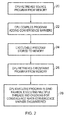
- FIG 2 shows a sequence of steps which may be carried out by a data processing system such as that illustrated in Figure 1 , in which a CPU compiles a source program for execution by a GPU.
- the CPU retrieves the source program from memory and at step 22 compiles this source program adding convergence markers at identified appropriate points within that program (as will be discussed in more detail with reference to the figures which follow).
- the thus-compiled executable program is then stored by the CPU back into the memory at step 24.
- the GPU retrieves this executable program from the memory and at step 28 executes the program in a single instruction multiple data (SIMD) fashion, executing multiple threads in parallel.
- SIMD single instruction multiple data
- Figure 3A shows an example sequence of program instructions, used here to support the discussion of the present techniques. It will be appreciated that only the control flow instructions in the example program code of Figure 3A are shown, since these are the instructions of relevance to the application of the present techniques, and the data processing instructions which would make up the remainder of a "full" program have been omitted (for clarity of illustration only).
- Figure 3B shows the control flow graph (CFG) corresponding to the program instructions of Figure 3A . It will be recognised that several different execution paths are possible through the CFG of Figure 3B , corresponding to the possible paths shown from the first explicitly represented program instruction (BBO) in at Figure 3A to the exit from the final program instruction of Figure 3A (BB5).
- CFG control flow graph
- Figure 3C shows the particular execution paths taken by four example threads (T0, T1, T2, T3). All four threads are part of the same kernel (executing the sequence of instructions shown in Figure 3A ) and execute in parallel (SIMD) to begin with. Accordingly, as shown in Figure 3C , all four threads follow the execution path from BB0 to BB1. Then, at BB1, threads T0 and T1 separate from threads T2 and T3, due to a different outcome of the "if" condition tested at BB1. Due to the different execution paths taken by the threads T0, T1 and T2, T3 the hardware of the apparatus executing these threads (e.g.
- the GPU 14 of Figure 1 selects threads T0, T1 for further execution and places threads T2, T3 in a waiting state for later further execution. Execution of threads T0, T1 continues with execution of the program instructions represented by BB2. If a convergence marker has been added to the compiled program at BB2 (see step 22 of Figure 2 ) then the hardware of the GPU can perform its convergence checks at this point, to determine which threads should now be progressed further in the process of execution. This being the case (i.e. that the convergence marker was set at BB2), the waiting threads, T2, T3 are then selected for further execution, whilst T0, T1 wait, because BB3 precedes BB4 in program count order.
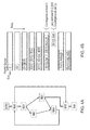
- Figure 4A reproduces the control flow graph of Figure 3B
- Figure 4B shows the application of present techniques to the analysis of the control flow graph of Figure 4A through the use of a priority queue by the compiler in one embodiment.
- the priority queue is populated by "path items", each of which represents a sequence of basic blocks starting from the entry node (E) to a basic block currently waiting for execution. Items stored in the priority queue are stored in the order of the relative placement in memory of the basic blocks. Initially, the priority queue is populated by just one item, representing the entry node E.
- an existing path item in the priority queue is removed and the execution path is extended by suffixing a successor basic block to the existing path.
- the path item E is removed and replaced with a path item E0, representing the execution path from the entry node to the basic block BB0.
- This path item E0 is then removed at the next iteration and since basic block BB0 has two successor basic blocks (BB1 and BB5) two path items are created for addition to the priority queue, both having the same E0 stem and the first appended with "1" to represent the execution path to BB1, and the second appended with "5" to represent the execution path to BB5. Note also that because BB1 is at a lower program counter value than BB5, E01 is placed ahead of E05 in the priority queue.
- This prioritisation (in terms of program counter order) of path items as they are added to the priority queue also means that when E012 is removed and then appended with 4, the resulting path item E0124 is placed after E013 in the priority queue, since basic block BB3 precedes basic block BB4 in program counter order.
- a further point to note with respect to the processing of the priority queue shown in Figure 4B is the extension of the path item E013 to represent the execution path leading to BB4.
- E013 is removed from the priority queue and should be appended with "4" to represent the extension of the execution path from BB3 to BB4
- the existence of another execution path leading to BB4 is identified by the pre-existence of the path item E0124 in the priority queue.
- the existing path item E0124 and the proposed path item E0134 are combined to give a combined path E01 ⁇ 2,3 ⁇ 4 which is then added to the priority queue. Since the analysis of this step has explicitly recognised the convergence of two separate execution paths into one basic block (at BB4), the convergence marker is then added at this point.
- the particular placement of the convergence marker within the program could vary, as long as it is recognised to be associated with the convergence of the execution paths at BB4.
- the convergence marker could be placed as a new first program instruction within the basic block B4, or for example could be placed at the end of each of the basic blocks BB2 and BB3, as long as the effect on the execution apparatus is that the convergence analysis is carried out before the execution of threads at BB4, in order to take advantage of the possible addition to the number of threads which can be executed in parallel at BB4.
- E013 is removed from the priority queue and should be appended with "5" in order to represent the execution path from BB3 to BB5
- the existing path leading to BB5 in the priority queue i.e. E05 is identified and thus a combined path is also formed here, represented in Figure 4B by E0 ⁇ 13, NULL ⁇ 5 representing these two possible paths.
- an execution path from BB4 leads to BB0 and hence when the path item E01 ⁇ 2,3 ⁇ 4 is extended with "0" in order to represent this, this execution path is identified as a loop in that a possible execution path leads from BB0 back to BB0.
- this path item is not added back into the priority queue, and furthermore possible exits from this loop (in this example from BB0 and from BB3) are identified by iteratively proceeding around the loop, determining if each basic block thus encountered gives the possibility of exiting the loop. The corresponding "loop exit" basic blocks thus found are marked with the convergence marker.
- the processing of the priority queue continues until it is empty, which in the example of Figures 4A and 4B corresponds to the removal of the path item which has been built up representing the possible paths leading to BB5 and then to the exit node.
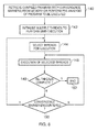
- FIG. 5 shows a sequence of steps which are taken in one embodiment when carrying out the above described method of adding convergence markers during a compilation procedure.
- the flow begins at step 100 where the priority queue is initialised with an entry basic block (E). Then, at step 102 it is determined if the priority queue is empty. Of course at the first iteration immediately following step 100 this cannot be the case, but when this is the case (to be discussed in more detail below) the flow precedes to step 104, where the steps end. However, when the priority queue is not empty then the flow proceeds to step 106, where a path P (also referred to herein as a "path item”) is removed from the head of the priority queue.
- a path P also referred to herein as a "path item”
- step 108 a path P' for each successor or successors of the last basic block (BB) of P is created. If there are no successors to P, then the flow (see step 110) returns to step 102. When such a successor or successors are present, then the flow proceeds to step 112, where it is determined if this successor (or the successor presently being considered in the case of multiple successors) is already present in the path P, meaning that a loop has been identified. If this is the case the flow proceeds to step 114 where all exit basic blocks of this loop are marked as a convergence point (i.e. the convergence marker is added in association with each of these basic blocks).
- step 116 if there is another successor to P, the flow returns to step 112. When there are no further successors, the flow returns from step 116 to step 112.
- step 118 it is determined if the successor S under consideration is already present on another path Q in the priority queue. If this is the case then the flow proceeds to step 120, where paths P and Q are combined, the successor basic block S is marked as a convergence point and the combined path is replaced in the priority queue. The flow then proceeds to step 122, where it is determined if there is another successor of the path P to be considered. If there is, the flow returns to step 112, whereas if there is not the flow returns to step 102.
- step 118 if the successor basic block S currently under consideration is not present on another path Q already present in the priority queue then the flow proceeds to step 124, where P' is added to the priority queue respecting program counter order, i.e. such that the path items present in the priority queue are ordered such that the program counter value associated with the last basic block in that path item (for example associated with the last instruction in that last basic block) determines its position in the queue.
- step 126 it is determined if P' has not been added to the head of the priority queue. This being the case, the flow proceeds via step 128, where the basic block S is marked as a convergence point (i.e. the convergence marker is added to the program in association with this basic block).
- step 122 it is determined if there is another successor basic block to be considered for the path P'.
- step 102 it is determined if there is another successor basic block to be considered for the path P'.
- step 102 it is determined if there is another successor basic block to be considered for the path P'.
- Figure 6 shows a sequence of steps which are taken in one embodiment when executing a computer program compiled using the present techniques to add convergence markers, or when executing a program and also performing an initial step of analysis (and adding convergence markers).
- the apparatus which is to execute the computer program e.g. the GPU 14 of Figure 1
- multiple threads are initialised in order to perform SIMD execution of this program, corresponding to the multiple data items to which the executable should be applied.
- the apparatus selects one or more of these threads for parallel execution. This in particular involves determining from all the threads which could be executed which subset thereof represents a group of threads which may be executed in lock-step with one another in order to take advantage of the resource usage efficiency which results from such parallelism. Execution of the subset of threads thus selected then begins at step 146, and it should be noted that this execution may also involve some executing threads being put on hold when for example a branch is encountered and the apparatus selects only a subset of the currently executing threads for further execution (for the time being). At step 148 it is determined if the execution of all possible threads is now complete.
- step 150 it is determined if a convergence marker added during the compilation process has been encountered by at least one of the executing threads. Whilst this is not the case, the flow returns to step 146 for further execution of these selected threads to continue. Otherwise, if the convergence marker is encountered, then the flow proceeds back to step 144 for a new assessment of the subset of threads which now should be executed in parallel to be carried out. Once all threads have completed (see step 148) then the flow ends at step 152 (i.e. execution of this compiled executable is complete.
- FIG. 7 schematically illustrates a general purpose computing device 200 of the type that may be used to implement the above described techniques.
- the general purpose computing device 200 includes a central processing unit 202, a random access memory 204 and a read only memory 206, connected together via bus 222. It also further comprises a network interface card 208, a hard disk drive 210, a display driver 212 and monitor 214 and a user input/output circuit 216 with a keyboard 218 and mouse 220 all connected via the common bus 222. It further comprises a graphics processing unit 224 also connected to the common bus 222.
- the central processing unit 202 will execute computer program instructions that may for example be stored in the random access memory 204 and/or the read only memory 206.
- Program instructions could instead or additionally be retrieved from the hard disk drive 210 or dynamically downloaded via the network interface card 208.
- the result of these operations by the central processing unit 202 may be stored locally in the RAM 204 or the HDD 210, or could be transmitted to a remote location via the NIC 208.
- Such a compiled computer program could then be executed by the GPU 224, having retrieved it from the location at which it was stored by the CPU 202.
- the results of the processing performed by the CPU 202 and the GPU 224 may be displayed to a user via a connected display driver 212 and monitor 214.
- User inputs for controlling the operation of the general purpose computing device 200 may be received via a connected user input output circuit 216 from the keyboard 218 or the mouse 220.
- the computer programs executed by the general purpose computing device 200 could be written in a variety of different computer languages.
- the computer programs may be stored locally on a recording medium or dynamically downloaded to the general purpose computing device 200.
- the general purpose computing device 200 can perform the above described techniques of compilation and/or program execution and can be considered to form an apparatus for performing the above described techniques of compilation and/or program execution.
- the architecture of the general purpose computing device 200 could vary considerably and Figure 7 is only one example.
- the words “configured to" or “arranged to” are used to mean that an element of an apparatus has a configuration able to carry out the defined operation.
- a “configuration” means an arrangement or manner of interconnection of hardware or software.
- the apparatus may have dedicated hardware which provides the defined operation, or a processor or other processing device may be programmed to perform the function.
- Configured to" or “arranged to” does not imply that the apparatus element needs to be changed in any way in order to provide the defined operation.
Landscapes
- Engineering & Computer Science (AREA)
- Theoretical Computer Science (AREA)
- General Engineering & Computer Science (AREA)
- Software Systems (AREA)
- Physics & Mathematics (AREA)
- General Physics & Mathematics (AREA)
- Devices For Executing Special Programs (AREA)
Abstract
Description
- The present disclosure relates to the field of data processing. More particularly it relates to the determination of branch convergence in a sequence of program instructions.
- A set of program instructions for execution by a data-processing apparatus may not only result in execution in a simple, linear manner, i.e. wherein program instructions are executed in sequential order, from a first instruction in a sequence to a last instruction in the sequence. This is because conditions set out in individual program instructions may cause the program flow to take a branch from a given program instruction to another program instruction in the sequence, either skipping forwards in the sequence, or stepping back to a previous program instruction in the sequence. Such possible branching and looping in the execution of a sequence of program instructions may be of particular significance in the context of a data processing apparatus which is capable of executing multiple threads running the same kernel, since performance benefits result from executing such parallel threads in lock-step to make more efficient use of the resources of the data processing apparatus. However, when threads diverge due to different conditions for each thread resulting in those threads taking different branches, such parallelism may be lost. There may however be points at which the separated threads come together again and the opportunity for improved performance through parallel lock-step execution is once more available. The present disclosure relates to the identification of such convergence points.
- At least some embodiments of the present techniques provide a method of compiling a sequence of program instructions to generate a compiled program comprising: identifying basic blocks of program instructions, wherein each basic block has only one entry point and only one exit point; determining at least one execution path which leads to each basic block; when more than one execution path leads to a selected basic block, adding a convergence marker to the compiled program associated with the selected basic block; and when a loop path exists from a further selected basic block to the further selected basic block, adding the convergence marker to the compiled program associated with each exit basic block for the loop path.
- At least some embodiments of the present techniques provide an apparatus for compiling a sequence of program instructions to generate a compiled program, when the apparatus has a configuration to carry out the above method of compiling a sequence of program instructions.
- At least some embodiments of the present techniques provide a computer readable storage medium storing a computer program which when executed on a computer causes the computer to carry out the above method of compiling a sequence of program instructions.
- At least some embodiments of the present techniques provide software which when executed on a computer causes the computer to carry out the above method of compiling a sequence of program instructions.
- At least some embodiments provide a method of parallel execution of a computer program using multiple execution threads, wherein the computer program comprises a sequence of program instructions, the method comprising: identifying basic blocks of program instructions, wherein each basic block has only one entry point and only one exit point; determining at least one execution path which leads to each basic block; when more than one execution path leads to a selected basic block, adding a convergence marker to the computer program associated with the selected basic block; when a loop path exists from a further selected basic block to the further selected basic block, adding the convergence marker to the computer program associated with each exit basic block for the loop path; and executing the multiple execution threads, wherein executing the multiple execution threads comprises: when a first subset of the multiple execution threads takes a first execution path from a divergent basic block and a second subset of the multiple execution threads takes a second execution path from the divergent basic block, causing the second subset to wait; and when the convergence marker is encountered selecting at least one thread of the multiple execution threads for execution in accordance with predetermined parallel execution rules.
- At least some embodiments provide an apparatus for parallel execution of a computer program, wherein the apparatus has a configuration to carry out the above method of parallel execution of a computer program using multiple execution threads.
- At least some embodiments of the present techniques provide a computer readable storage medium storing a computer program which when executed on a computer causes the computer to carry out the above method of parallel execution of a computer program using multiple execution threads.
- At least some embodiments of the present techniques software which when executed on a computer causes the computer to carry out the above method of parallel execution of a computer program using multiple execution threads.
- The present techniques will be described further, by way of example only, with reference to embodiments thereof as illustrated in the accompanying drawings, in which:
-
Figure 1 schematically illustrates an apparatus in one embodiment comprising a CPU and a GPU; -
Figure 2 is a flow diagram showing a sequence of steps carried out in one embodiment when a CPU is used to compile a source program for execution by a GPU in a parallel execution manner; -
Figure 3A shows the structure of an example sequence of program instructions; -
Figure 3B shows a Control Flow Graph (CFG) for the sequence of program instructions shown inFigure 3A ; -
Figure 3C shows the CFG ofFigure 3B , with example execution paths for four threads which are executed in parallel; -
Figure 4 shows the CFG ofFigure 3B ; -
Figure 4B shows the evolution of a priority queue used when determining convergence points in the sequence of program instructions ofFigure 3A in one embodiment; -
Figure 5 shows a sequence of steps which are taken in the method of one embodiment when using a priority queue to determine convergence points in a sequence of program instructions; -
Figure 6 shows a sequence of steps which are taken in one embodiment when executing a compiled program to which convergence markers have been added at the compilation stage in one embodiment; and -
Figure 7 schematically illustrates a general purpose computing device which supports both compilation and execution in one embodiment. - At least some embodiments provide a method of compiling a sequence of program instructions to generate a compiled program comprising: identifying basic blocks of program instructions, wherein each basic block has only one entry point and only one exit point; determining at least one execution path which leads to each basic block; when more than one execution path leads to a selected basic block, adding a convergence marker to the compiled program associated with the selected basic block; and when a loop path exists from a further selected basic block to the further selected basic block, adding the convergence marker to the compiled program associated with each exit basic block for the loop path.
- One technique for finding the convergence points in a sequence of program instructions is to use an immediate post-dominator technique whereby basic blocks of program instructions are first identified, i.e. those sets of instructions which do not contain the possibility for branching in that they only have one point of entry and one point of exit, and to represent those basic blocks in a control flow graph. Accordingly a sequence of instructions can be grouped together as a basic block up to an instruction where the opportunity to deviate from sequential instruction execution exists, whereafter a new basic block must begin. A node Z is said to post-dominate a node N in a control flow graph if all paths to the exit node of the graph starting from N must go through Z. The immediate post-dominator of a node N is the post-dominator of N that does not strictly post-dominate any other strict post-dominators of N. The present technique recognises that although such an immediate post-dominator represents a possible convergence point in the control flow graph, in fact the immediate post-dominator approach is one that may omit some convergence points which can result from irregular nesting and control flows, and thus opportunities for efficient parallel execution of multiple threads executing the program instructions may be missed. The present technique addresses this issue by identifying those basic blocks to which more than one execution path leads and adding convergence markers within the control flow at that point. Further, those execution paths which form a loop are identified and convergence markers are added at each basic block along such a loop path where a possible exit from that loop path exists. This technique identifies convergence points which can be missed by the immediate post-dominator technique and thus supports improved parallel execution of multiple threads, where the convergence markers are used in execution to reassess which execution threads should be executed in parallel with one another in order to make efficient use of the resources of the data processing apparatus. It should be noted that the addition of a convergence marker associated with a basic block may be implemented in a number of ways: the marker could be added within the basic block, at a position preceding it, and so on, as long as the apparatus executing the compiled program understands which basic block the marker is associated with.
- The above described identification of convergence points in the control flow graph associated with a sequence of program instructions may be provided in a variety of ways, but in some embodiments the determining step comprises: iteratively processing a queue of path items, wherein each path item comprises an indication of at least one basic block, and each iterative step comprises: removing a prior path item from a first position in the queue; and generating a path item comprising the prior path item appended with an indication of a further basic block, wherein an execution path leads from the at least one basic block to the further basic block.
- Thus, in order to process the basic blocks of program instructions, i.e. the nodes of the corresponding control flow graph, the present techniques propose the use of a queue of path items, sometimes referred to herein as a priority queue, which is built up from indications of basic blocks. An iterative procedure of processing is proposed wherein, starting from the first entry node of the control flow graph, path items are added to the queue, which path items initially comprise a simple indication of the entry basic block to the control flow graph, and to which are appended indications of further basic blocks within the control flow graph to which an execution path leads from a path item already in the queue. Accordingly, an iterative process is set up wherein path items in the queue are grown by adding indications of basic blocks which form an execution path. Additional path items may be added to the queue when a branch from a basic block leads to more than one basic block, i.e. more than one execution path can be followed from that basic block. At each iteration an existing path item is taken from the priority queue, in particular from a "first position" in the queue, wherein it will be understood that this "first position" could be given by any predefined ordering of the queue, as long as such ordering is maintained, and a new path item is generated based on the path item just removed from the queue by appending that path item with an indication of a basic block to which an execution path leads from that removed path item. This thus enables the queue of path items to be developed, representing each possible execution path through the sequence of program instructions.
- In some embodiments the method further comprises: adding the path item to a selected position in the queue such that the path items in the queue are ordered in program counter order with respect to a last basic block in each path item. This thus enables the queue to be prioritised, such that path items representing execution paths through the sequence of program instructions are ordered so that program counter order is respected. This may also correspond to a prioritisation which is used by the apparatus executing the compiled program to select between threads for execution.
- The present technique further recognises that the ordering with which such path items are built up in the queue may have significance with regard to identifying convergence points within the compiled program, and in some embodiments when the path item is added other than as a first path item in the ordering, the convergence marker is added to the compiled program associated with the further basic block. Thus, a path item which ends with a basic block which causes it to be placed not in the first position in the ordering of the queue, because another path item in the queue has a basic block which comes earlier in program counter order (for example as determined by reference to the last program instruction in each basic block) then the present technique recognises that the path item being added (not in the first position) represents a potential for convergence since threads following another execution path may have executed in advance of a thread following this execution path, and convergence between these threads may then be possible. Hence, the convergence marker is also associated with this further basic block (i.e. the basic block appended to the path item at this iteration) to enable this possible convergence here to be taken advantage of.
- In some embodiments each iterative step comprises: adding a further path item to the queue when a further execution path leads from the at least one basic block to a second further basic block, wherein the further path item comprises the prior path item appended with an indication of the second further basic block. Thus, when more than one execution path leads from the basic block (i.e. to the further basic block and to a second further basic block) the iterative step adds another (further) path item to the queue corresponding to this further execution path. As in the case of the first path item, this further path item then represents a concatenation of basic blocks leading to the basic block under consideration and then to the second further basic block to which this further execution path leads. In other words, where a basic block is encountered by the method when iteratively processing the queue, where that basic block (through branching) has possible execution paths leading to more than one further basic block, a corresponding path item representing an execution path through the sequence of program instructions to each of the possible targets of that branching is then added to the queue.
- In some embodiments the method further comprises: when a further prior path item in the queue comprises the indication of the further basic block, modifying the further prior path item to indicate alternative paths to the further basic block; and adding the convergence marker to the compiled program associated with the further basic block. Thus, the iterative procedure of processing the queue may identify another path item already in the queue (a further prior path item) which already represents a possible execution path to the further basic block (i.e. to that basic block to which an execution path is currently being constructed by this iterative step). In other words, the method, at this iterative step, has thus identified two possible execution paths which lead to the same basic block. In this situation, the existing path item in the queue (the further prior path item) is then modified to indicate the alternative paths to the further basic block, and furthermore it is recognised here that this further basic block then represents a convergence point in the control flow graph and the convergence marker is then added to the compiled program in association with this further basic block. As mentioned above the convergence marker may be added to the further basic block itself, or for example to the end of the basic blocks preceding it, or in another position appropriate to the intended execution of this compiled program, such that appropriate reassessment by the execution circuitry of which groups of the multiple execution threads should be executed in parallel with one another at this point can then be carried out.
- It may be the case that from a given basic block an execution path is identified which leads to a basic block which is already present in another path item which is already in the queue, in other words a loop may be identified. Thus, in some embodiments when the prior path item comprises the indication of the further basic block the path item is the loop path. Thus, a loop path may be identified by this mechanism within the iterative process and, as mentioned above, the convergence marker can then be added to the compiled program associated with each exit basic block for this loop path.
- In such embodiments the identification of exit basic blocks from the loop path may be provided in a number of ways, but in some embodiments the method further comprises, when the prior path item comprises the indication of the further basic block, iteratively processing each basic block in this path item, and at each iterative step, when a path leads from the basic block being processed which exits the loop path, adding the convergence marker to the compiled program associated with the basic block being processed. Exit points from this loop path may thus be efficiently identified and marked with the convergence marker.
- As mentioned above, adding the convergence marker to the compiled program may involve adding a convergence marker at a number of different specific positions, depending on the particular requirements of how the convergence marker is to be used by the apparatus which will execute the compiled program, but in some embodiments adding the convergence marker to the compiled program associated with the selected basic block comprises adding the convergence marker immediately preceding the selected basic block. Thus, the apparatus executing the compiled program will then encounter the convergence marker immediately before executing the selected basic block of (compiled) program instructions where convergence has been recognised by the present method as potentially occurring. Thus this represents an expedient point for the executing apparatus to reassess which threads should now be executed in parallel in order to make efficient use of the apparatus resources.
- Similarly, in the situation of adding the convergence marker in response to the identification of a loop path (i.e. to the exit points from that loop path) in some embodiments adding the convergence marker to the compiled program associated with each exit basic block for the loop path comprises adding the convergence marker immediately preceding each exit basic block.
- At least some embodiments provide an apparatus for compiling a sequence of program instructions to generate a compiled program, wherein the apparatus has a configuration to carry out the method of any of the above described embodiments of that method.
- At least some embodiments provide a computer readable storage medium storing a computer program which when executed on a computer causes the computer to carry out the method of any of the above described embodiments of that method.
- At least some embodiments provide software which when executed on a computer causes the computer to carry out the method of any of above described embodiments of that method.
- At least some embodiments provide a method of parallel execution of a computer program using multiple execution threads, wherein the computer program comprises a sequence of program instructions, the method comprising: identifying basic blocks of program instructions, wherein each basic block has only one entry point and only one exit point; determining at least one execution path which leads to each basic block; when more than one execution path leads to a selected basic block, adding a convergence marker to the computer program associated with the selected basic block; when a loop path exists from a further selected basic block to the further selected basic block, adding the convergence marker to the computer program associated with each exit basic block for the loop path; and executing the multiple execution threads, wherein executing the multiple execution threads comprises: when a first subset of the multiple execution threads takes a first execution path from a divergent basic block and a second subset of the multiple execution threads takes a second execution path from the divergent basic block, causing the second subset to wait; and when the convergence marker is encountered selecting at least one thread of the multiple execution threads for execution in accordance with predetermined parallel execution rules.
- The execution of the computer program may thus comprise an initial stage of analysis of basic blocks of the program instructions which is carried out in an analogous fashion to that described above with respect to the compilation method, wherein potential convergence points within the program are identified and marked with the convergence marker. Thereafter, when executing multiple execution threads, the method comprises identifying divergent basic blocks where more than one execution path leads from that basic block, and at this point identifying subsets of the multiple execution threads which take those paths, and causing at least one subset to wait, whilst another continues execution, since where these subsets of execution threads have taken different paths, the benefits of parallel execution of both subsets do not occur and it may be more efficient to allow these subsets to be executed in a serial, rather than parallel, manner. Following this, when the convergence marker added to the computer program is then encountered, predetermined parallel execution rules which define when it is appropriate (in terms of efficient use of the execution apparatus resources) to execute selected multiple execution threads in parallel can then be used to determine which of the threads of the multiple execution threads should now be executed in parallel with one another (until another divergent basic block is encountered).
- In some embodiments selecting the at least one thread of the multiple execution threads for execution in accordance with the predetermined parallel execution rules comprises selecting a group of threads for which a next instruction to be executed is earliest in program counter order. This prioritisation of a group of threads on the basis of program counter order may then correspond to the manner in which path items were ordered and processed in the queue when the above described queue of the compilation method of the present techniques was employed.
- At least some embodiments provide an apparatus for parallel execution of a computer program, wherein the apparatus has a configuration to carry out any of the above mentioned methods of parallel execution of a computer program using multiple execution threads.
- This execution apparatus may take a variety of forms, but in some embodiments the apparatus is a graphics processing unit. Graphics processing units may be required to execute a great number of execution threads in parallel, and be able to derive processing efficiency from such parallelization, and the present techniques support efficient use of such an apparatus, in regard to supporting selection of the points in the execution process when the identification (and re-identification) of which threads should be executed in parallel with one another is to be carried out. This is notable because this assessment and re-assessment of which threads to operate in parallel itself represents a non-trivial processing task for the execution apparatus and if carried out too frequently can reduce the processing efficiency, yet if carried out too infrequently, such parallelization benefits as may be available may not be fully taken advantage of. The present techniques allow a useful balance to be struck between these positions.
- At least some embodiments provide a computer readable storage medium storing a computer program which when executed on a computer causes the computer to carry out the above mentioned embodiments of the method of parallel execution of a computer program using multiple execution threads.
- At least some embodiments provide software which when executed on a computer causes the computer to carry out any of the above described embodiments of the method of parallel execution of a computer program using multiple execution threads.
- Some particular embodiments will now be described with reference to the Figures.
-
Figure 1 schematically illustrates adata processing apparatus 10 in one embodiment. Thedata processing apparatus 10 comprises a central processing unit (CPU) 12 and a graphics processing unit (GPU) 14. Each of theCPU 12 and GPU 14 can perform data processing operations, which are carried out by retrieving data processing instructions and data to be processed from thememory 16 and, where appropriate, writing modified data back to thememory 16. Each of theCPU 12 and GPU 14 are provided with arespective cache 18, 20 in order to reduce the latency associated with the retrieval of instructions or data from thememory 16. It will be appreciated that both theCPU 12 and GPU 14 may perform a great variety of data processing operations, but of particular relevance to the discussion of the present techniques are the ability of the GPU 14 to perform parallel execution of a computer program using multiple execution threads and the ability of theCPU 12 to compile that computer program from a source program stored in thememory 16 into a executable program also stored in thememory 16 which the GPU 14 can retrieve and then execute in this parallelized manner. Further, a particular feature of theCPU 12 and GPU 14 shown inFigure 1 is the ability of theCPU 12 to add "convergence markers" to the computer program which it compiles, these being indicative of points at which the CPU has determined that it may be beneficial for the GPU 14 to check for convergence between the multiple execution threads which it executes when executing the program compiled by theCPU 12. As mentioned above, more efficient usage of the resources of the data processing apparatus may be gained by the GPU 14 when carrying out parallel execution of the program using multiple execution threads by selecting an appropriate subset of those multiple execution threads for parallel execution at any given point in time. However, since the determination of this subset itself also consumes processing resources of the data processing system, such efficiency may be lost if this determination is performed too frequently. As mentioned above, the present techniques address this issue by the selection of points within a compiled computer program at which convergence markers should be added (for example by theCPU 12 in the example ofFigure 1 ). Finally, note that there is no requirement for theCPU 12 and GPU 14 to form part of the same data processing apparatus, and thedata processing system 10 which comprises both theCPU 12 and the GPU 14 is merely one example. In other embodiments the CPU and GPU could respectively form part of entirely separate data processing apparatuses. Indeed, the present techniques are related to the compilation and execution of computer programs and are equally applicable to data processing apparatuses which do not have the specialised processing units such as theCPU 12 and GPU 14 of the embodiment ofFigure 1 . -
Figure 2 shows a sequence of steps which may be carried out by a data processing system such as that illustrated inFigure 1 , in which a CPU compiles a source program for execution by a GPU. Atstep 20 the CPU retrieves the source program from memory and atstep 22 compiles this source program adding convergence markers at identified appropriate points within that program (as will be discussed in more detail with reference to the figures which follow). The thus-compiled executable program is then stored by the CPU back into the memory atstep 24. Then, atstep 26, the GPU retrieves this executable program from the memory and atstep 28 executes the program in a single instruction multiple data (SIMD) fashion, executing multiple threads in parallel. For example, in the context of a GPU executing such an executable program, this SIMD execution may correspond to a sequence of program instructions being applied to multiple pixels of a graphics display, with data corresponding to each pixel position being processed by the same sequence of instructions. The convergence markers added to the executable program atstep 22 by the CPU during the compilation process are then encountered (at step 28) by the GPU when executing this program, and when such a convergence marker is encountered by the GPU it checks for convergence between the multiple execution threads which it is currently executing, i.e. it reassesses which of the currently defined threads should be actively executed in parallel with one another in order to make efficient usage of the resources of the data processing system. -
Figure 3A shows an example sequence of program instructions, used here to support the discussion of the present techniques. It will be appreciated that only the control flow instructions in the example program code ofFigure 3A are shown, since these are the instructions of relevance to the application of the present techniques, and the data processing instructions which would make up the remainder of a "full" program have been omitted (for clarity of illustration only).Figure 3B shows the control flow graph (CFG) corresponding to the program instructions ofFigure 3A . It will be recognised that several different execution paths are possible through the CFG ofFigure 3B , corresponding to the possible paths shown from the first explicitly represented program instruction (BBO) in atFigure 3A to the exit from the final program instruction ofFigure 3A (BB5).Figure 3C shows the particular execution paths taken by four example threads (T0, T1, T2, T3). All four threads are part of the same kernel (executing the sequence of instructions shown inFigure 3A ) and execute in parallel (SIMD) to begin with. Accordingly, as shown inFigure 3C , all four threads follow the execution path from BB0 to BB1. Then, at BB1, threads T0 and T1 separate from threads T2 and T3, due to a different outcome of the "if" condition tested at BB1. Due to the different execution paths taken by the threads T0, T1 and T2, T3 the hardware of the apparatus executing these threads (e.g. the GPU 14 ofFigure 1 ) selects threads T0, T1 for further execution and places threads T2, T3 in a waiting state for later further execution. Execution of threads T0, T1 continues with execution of the program instructions represented by BB2. If a convergence marker has been added to the compiled program at BB2 (seestep 22 ofFigure 2 ) then the hardware of the GPU can perform its convergence checks at this point, to determine which threads should now be progressed further in the process of execution. This being the case (i.e. that the convergence marker was set at BB2), the waiting threads, T2, T3 are then selected for further execution, whilst T0, T1 wait, because BB3 precedes BB4 in program count order. Note that it is not essential for execution of multiple threads to be prioritised in terms of the program counter values of the instructions being executed, but this represents one manner (used here) of prioritising between multiple execution threads which may be selected. Once the execution of BB3 has completed, a convergence marker may then cause the apparatus once again to determine which subset of the multiple execution threads should then be selected for execution, and in the example ofFigure 3C , where thread T2 follows the execution path from BB3 to BB4, whilst thread T3 follows the execution path from BB3 to BB5, the apparatus can select T0, T1 and T2 as a subset of the multiple execution threads to be executed in parallel next, namely by the execution for each thread of the instructions represented by BB4. In the meantime, thread T3 waits. Thus, it will be appreciated from the above discussion ofFigures 3A-C that the selection of the points in the compiled program at which the compiler adds the convergence markers represents both an opportunity for efficient usage of the execution apparatus resources, by combining threads for parallel execution where those threads are executing the same basic blocks of program instructions, yet itself also represents a processing burden on the execution apparatus, due to the convergence checks which the execution apparatus must carry out in order to correctly determine such a subset of threads to be executed in parallel. - The present techniques address this issue as is discussed now with reference to
Figures 4A and 4B. Figure 4A reproduces the control flow graph ofFigure 3B , whilstFigure 4B shows the application of present techniques to the analysis of the control flow graph ofFigure 4A through the use of a priority queue by the compiler in one embodiment. The priority queue is populated by "path items", each of which represents a sequence of basic blocks starting from the entry node (E) to a basic block currently waiting for execution. Items stored in the priority queue are stored in the order of the relative placement in memory of the basic blocks. Initially, the priority queue is populated by just one item, representing the entry node E. At each of the steps (levels) shown in the time evolution ofFigure 4B , an existing path item in the priority queue is removed and the execution path is extended by suffixing a successor basic block to the existing path. For example, from the first to the second stage shown inFigure 4B (proceeding from top to bottom) the path item E is removed and replaced with a path item E0, representing the execution path from the entry node to the basic block BB0. This path item E0 is then removed at the next iteration and since basic block BB0 has two successor basic blocks (BB1 and BB5) two path items are created for addition to the priority queue, both having the same E0 stem and the first appended with "1" to represent the execution path to BB1, and the second appended with "5" to represent the execution path to BB5. Note also that because BB1 is at a lower program counter value than BB5, E01 is placed ahead of E05 in the priority queue. This prioritisation (in terms of program counter order) of path items as they are added to the priority queue also means that when E012 is removed and then appended with 4, the resulting path item E0124 is placed after E013 in the priority queue, since basic block BB3 precedes basic block BB4 in program counter order. - A further point to note with respect to the processing of the priority queue shown in
Figure 4B is the extension of the path item E013 to represent the execution path leading to BB4. When E013 is removed from the priority queue and should be appended with "4" to represent the extension of the execution path from BB3 to BB4, the existence of another execution path leading to BB4 is identified by the pre-existence of the path item E0124 in the priority queue. As a result, the existing path item E0124 and the proposed path item E0134 are combined to give a combined path E01 {2,3} 4 which is then added to the priority queue. Since the analysis of this step has explicitly recognised the convergence of two separate execution paths into one basic block (at BB4), the convergence marker is then added at this point. Note that the particular placement of the convergence marker within the program could vary, as long as it is recognised to be associated with the convergence of the execution paths at BB4. For example, the convergence marker could be placed as a new first program instruction within the basic block B4, or for example could be placed at the end of each of the basic blocks BB2 and BB3, as long as the effect on the execution apparatus is that the convergence analysis is carried out before the execution of threads at BB4, in order to take advantage of the possible addition to the number of threads which can be executed in parallel at BB4. Similarly, note that when E013 is removed from the priority queue and should be appended with "5" in order to represent the execution path from BB3 to BB5, the existing path leading to BB5 in the priority queue i.e. E05 is identified and thus a combined path is also formed here, represented inFigure 4B by E0{13, NULL} 5 representing these two possible paths. - Furthermore, an execution path from BB4 leads to BB0 and hence when the path item E01 {2,3}4 is extended with "0" in order to represent this, this execution path is identified as a loop in that a possible execution path leads from BB0 back to BB0. In consequence, this path item is not added back into the priority queue, and furthermore possible exits from this loop (in this example from BB0 and from BB3) are identified by iteratively proceeding around the loop, determining if each basic block thus encountered gives the possibility of exiting the loop. The corresponding "loop exit" basic blocks thus found are marked with the convergence marker. The processing of the priority queue continues until it is empty, which in the example of
Figures 4A and 4B corresponds to the removal of the path item which has been built up representing the possible paths leading to BB5 and then to the exit node. -
Figure 5 shows a sequence of steps which are taken in one embodiment when carrying out the above described method of adding convergence markers during a compilation procedure. The flow begins atstep 100 where the priority queue is initialised with an entry basic block (E). Then, at step 102 it is determined if the priority queue is empty. Of course at the first iteration immediately followingstep 100 this cannot be the case, but when this is the case (to be discussed in more detail below) the flow precedes to step 104, where the steps end. However, when the priority queue is not empty then the flow proceeds to step 106, where a path P (also referred to herein as a "path item") is removed from the head of the priority queue. Then, following this, at step 108 a path P' for each successor or successors of the last basic block (BB) of P is created. If there are no successors to P, then the flow (see step 110) returns to step 102. When such a successor or successors are present, then the flow proceeds to step 112, where it is determined if this successor (or the successor presently being considered in the case of multiple successors) is already present in the path P, meaning that a loop has been identified. If this is the case the flow proceeds to step 114 where all exit basic blocks of this loop are marked as a convergence point (i.e. the convergence marker is added in association with each of these basic blocks). As mentioned above, these "loop exit" are identified by iteratively proceeding around the loop, determining if each basic block thus encountered gives the possibility of exiting the loop. Then fromstep 116, if there is another successor to P, the flow returns to step 112. When there are no further successors, the flow returns fromstep 116 to step 112. - If a loop is not identified at
step 112, then the flow proceeds to step 118, where it is determined if the successor S under consideration is already present on another path Q in the priority queue. If this is the case then the flow proceeds to step 120, where paths P and Q are combined, the successor basic block S is marked as a convergence point and the combined path is replaced in the priority queue. The flow then proceeds to step 122, where it is determined if there is another successor of the path P to be considered. If there is, the flow returns to step 112, whereas if there is not the flow returns to step 102. Returning to a consideration ofstep 118, if the successor basic block S currently under consideration is not present on another path Q already present in the priority queue then the flow proceeds to step 124, where P' is added to the priority queue respecting program counter order, i.e. such that the path items present in the priority queue are ordered such that the program counter value associated with the last basic block in that path item (for example associated with the last instruction in that last basic block) determines its position in the queue. The flow then proceeds to step 126 where it is determined if P' has not been added to the head of the priority queue. This being the case, the flow proceeds viastep 128, where the basic block S is marked as a convergence point (i.e. the convergence marker is added to the program in association with this basic block). The flow then proceeds to step 122, where (as described above) it is determined if there is another successor basic block to be considered for the path P'. As before, when this is not the case, the flow proceeds to step 102 and when this is the case the flow proceeds to step 112. Accordingly, by following the steps set out inFigure 5 , starting from a path item in the priority queue corresponding to an entry basic block and removing path items from the priority queue and suffixing them with further basic blocks to represent execution paths through the program, and under some circumstances adding path items back to the priority queue, a process is followed by which the priority queue is built up and then emptied and when finally the priority queue is empty, the procedure completes atstep 104. -
Figure 6 shows a sequence of steps which are taken in one embodiment when executing a computer program compiled using the present techniques to add convergence markers, or when executing a program and also performing an initial step of analysis (and adding convergence markers). Firstly, atstep 140, the apparatus which is to execute the computer program (e.g. the GPU 14 ofFigure 1 ) retrieves the compiled executable (with its embedded convergence markers from memory) or retrieves a program to be executed an performs a pre-analysis (such as in accordance with the steps ofFigure 5 ) in order to add convergence markers where appropriate. Then, atstep 142 multiple threads are initialised in order to perform SIMD execution of this program, corresponding to the multiple data items to which the executable should be applied. Then atstep 114 the apparatus selects one or more of these threads for parallel execution. This in particular involves determining from all the threads which could be executed which subset thereof represents a group of threads which may be executed in lock-step with one another in order to take advantage of the resource usage efficiency which results from such parallelism. Execution of the subset of threads thus selected then begins atstep 146, and it should be noted that this execution may also involve some executing threads being put on hold when for example a branch is encountered and the apparatus selects only a subset of the currently executing threads for further execution (for the time being). At step 148 it is determined if the execution of all possible threads is now complete. Whilst this is not the case when the flow proceeds to step 150 where it is determined if a convergence marker added during the compilation process has been encountered by at least one of the executing threads. Whilst this is not the case, the flow returns to step 146 for further execution of these selected threads to continue. Otherwise, if the convergence marker is encountered, then the flow proceeds back to step 144 for a new assessment of the subset of threads which now should be executed in parallel to be carried out. Once all threads have completed (see step 148) then the flow ends at step 152 (i.e. execution of this compiled executable is complete. -
Figure 7 schematically illustrates a generalpurpose computing device 200 of the type that may be used to implement the above described techniques. The generalpurpose computing device 200 includes acentral processing unit 202, arandom access memory 204 and a read onlymemory 206, connected together viabus 222. It also further comprises anetwork interface card 208, ahard disk drive 210, adisplay driver 212 and monitor 214 and a user input/output circuit 216 with akeyboard 218 andmouse 220 all connected via thecommon bus 222. It further comprises agraphics processing unit 224 also connected to thecommon bus 222. In operation, such as when carrying out the above described compilation process, thecentral processing unit 202 will execute computer program instructions that may for example be stored in therandom access memory 204 and/or the read onlymemory 206. Program instructions could instead or additionally be retrieved from thehard disk drive 210 or dynamically downloaded via thenetwork interface card 208. The result of these operations by thecentral processing unit 202, for example in the form of a compiled computer program ready for execution, may be stored locally in theRAM 204 or theHDD 210, or could be transmitted to a remote location via theNIC 208. Such a compiled computer program could then be executed by theGPU 224, having retrieved it from the location at which it was stored by theCPU 202. The results of the processing performed by theCPU 202 and theGPU 224 may be displayed to a user via aconnected display driver 212 and monitor 214. User inputs for controlling the operation of the generalpurpose computing device 200 may be received via a connected userinput output circuit 216 from thekeyboard 218 or themouse 220. - It will be appreciated that the computer programs executed by the general
purpose computing device 200, and in particular by either theCPU 202 or theGPU 224 could be written in a variety of different computer languages. The computer programs may be stored locally on a recording medium or dynamically downloaded to the generalpurpose computing device 200. When operating under control of an appropriate computer program, the generalpurpose computing device 200 can perform the above described techniques of compilation and/or program execution and can be considered to form an apparatus for performing the above described techniques of compilation and/or program execution. The architecture of the generalpurpose computing device 200 could vary considerably andFigure 7 is only one example. - Some further example configurations are set out in the following numbered clauses:
- 1. A method of parallel execution of a computer program using multiple execution threads, wherein the computer program comprises a sequence of program instructions, the method comprising:
- identifying basic blocks of program instructions, wherein each basic block has only one entry point and only one exit point;
- determining at least one execution path which leads to each basic block;
- when more than one execution path leads to a selected basic block, adding a convergence marker to the computer program associated with the selected basic block;
- when a loop path exists from a further selected basic block to the further selected basic block, adding the convergence marker to the computer program associated with each exit basic block for the loop path; and
- executing the multiple execution threads, wherein executing the multiple execution threads comprises:
- when a first subset of the multiple execution threads takes a first execution path from a divergent basic block and a second subset of the multiple execution threads takes a second execution path from the divergent basic block, causing the second subset to wait; and
- when the convergence marker is encountered selecting at least one thread of the multiple execution threads for execution in accordance with predetermined parallel execution rules.
- 2. The method as defined in clause 1, wherein selecting the at least one thread of the multiple execution threads for execution in accordance with the predetermined parallel execution rules comprises selecting a group of threads for which a next instruction to be executed is earliest in program counter order.
- 3. Apparatus for parallel execution of a computer program, wherein the apparatus has a configuration to carry out the method of
clause 1 or 2. - 4. The apparatus as defined in
clause 3, wherein the apparatus is a graphics processing unit. - 5. A computer readable storage medium storing a computer program which when executed on a computer causes the computer to carry out the method of
clause 1 or 2. - 6. Software which when executed on a computer causes the computer to carry out the method of
clause 1 or 2. - In the present application, the words "configured to..." or "arranged to" are used to mean that an element of an apparatus has a configuration able to carry out the defined operation. In this context, a "configuration" means an arrangement or manner of interconnection of hardware or software. For example, the apparatus may have dedicated hardware which provides the defined operation, or a processor or other processing device may be programmed to perform the function. "Configured to" or "arranged to" does not imply that the apparatus element needs to be changed in any way in order to provide the defined operation.
- Although illustrative embodiments have been described in detail herein with reference to the accompanying drawings, it is to be understood that the invention is not limited to those precise embodiments, and that various changes, additions and modifications can be effected therein by one skilled in the art without departing from the scope and spirit of the invention as defined by the appended claims. For example, various combinations of the features of the dependent claims could be made with the features of the independent claims without departing from the scope of the present invention.
Claims (15)
- A method of compiling a sequence of program instructions to generate a compiled program comprising:identifying basic blocks of program instructions, wherein each basic block has only one entry point and only one exit point;determining at least one execution path which leads to each basic block;when more than one execution path leads to a selected basic block, adding a convergence marker to the compiled program associated with the selected basic block; andwhen a loop path exists from a further selected basic block to the further selected basic block, adding the convergence marker to the compiled program associated with each exit basic block for the loop path.
- The method as claimed in claim 1, wherein the determining step comprises:iteratively processing a queue of path items, wherein each path item comprises an indication of at least one basic block, and each iterative step comprises:removing a prior path item from a first position in the queue; andgenerating a path item comprising the prior path item appended with an indication of a further basic block, wherein an execution path leads from the at least one basic block to the further basic block.
- The method as claimed in claim 2, further comprising:adding the path item to a selected position in the queue such that the path items in the queue are ordered in program counter order with respect to a last basic block in each path item.
- The method as claimed in claim 3, wherein when the path item is added other than as a first path item in the ordering, the convergence marker is added to the compiled program associated with the further basic block.
- The method as claimed in any of claims 2-4, wherein each iterative step comprises:adding a further path item to the queue when a further execution path leads from the at least one basic block to a second further basic block,wherein the further path item comprises the prior path item appended with an indication of the second further basic block.
- The method as claimed in any of claims 2-5, further comprising:when a further prior path item in the queue comprises the indication of the further basic block, modifying the further prior path item to indicate alternative paths to the further basic block; andadding the convergence marker to the compiled program associated with the further basic block.
- The method as claimed in any of claims 2-6, wherein when the prior path item comprises the indication of the further basic block the path item is the loop path.
- The method as claimed in claim 7, further comprising:when the prior path item comprises the indication of the further basic block, iteratively processing each basic block in this path item, and at each iterative step, when a path leads from the basic block being processed which exits the loop path, adding the convergence marker to the compiled program associated with the basic block being processed.
- The method as claimed in any preceding claim, wherein adding the convergence marker to the compiled program associated with the selected basic block comprises adding the convergence marker immediately preceding the selected basic block.
- The method as claimed in any preceding claim, wherein adding the convergence marker to the compiled program associated with each exit basic block for the loop path comprises adding the convergence marker immediately preceding each exit basic block.
- Apparatus for compiling a sequence of program instructions to generate a compiled program, wherein the apparatus has a configuration to carry out the method of any of claims 1-10.
- A computer readable storage medium storing a computer program which when executed on a computer causes the computer to carry out the method of any of claims 1-10.
- Software which when executed on a computer causes the computer to carry out the method of any of claims 1-10.
- A method of parallel execution of a computer program using multiple execution threads, wherein the computer program comprises a sequence of program instructions, the method comprising:identifying basic blocks of program instructions, wherein each basic block has only one entry point and only one exit point;determining at least one execution path which leads to each basic block;when more than one execution path leads to a selected basic block, adding a convergence marker to the computer program associated with the selected basic block;when a loop path exists from a further selected basic block to the further selected basic block, adding the convergence marker to the computer program associated with each exit basic block for the loop path; andexecuting the multiple execution threads, wherein executing the multiple execution threads comprises:when a first subset of the multiple execution threads takes a first execution path from a divergent basic block and a second subset of the multiple execution threads takes a second execution path from the divergent basic block, causing the second subset to wait; andwhen the convergence marker is encountered selecting at least one thread of the multiple execution threads for execution in accordance with predetermined parallel execution rules.
- The method as claimed in claim 14, wherein selecting the at least one thread of the multiple execution threads for execution in accordance with the predetermined parallel execution rules comprises selecting a group of threads for which a next instruction to be executed is earliest in program counter order.
Priority Applications (3)
| Application Number | Priority Date | Filing Date | Title |
|---|---|---|---|
| EP15386020.0A EP3106982B1 (en) | 2015-06-18 | 2015-06-18 | Determination of branch convergence in a sequence of program instructions |
| US15/168,368 US9990186B2 (en) | 2015-06-18 | 2016-05-31 | Determination of branch convergence in a sequence of program instruction |
| CN201610406030.1A CN106257412B (en) | 2015-06-18 | 2016-06-08 | Determination of branch convergence in program instruction sequence |
Applications Claiming Priority (1)
| Application Number | Priority Date | Filing Date | Title |
|---|---|---|---|
| EP15386020.0A EP3106982B1 (en) | 2015-06-18 | 2015-06-18 | Determination of branch convergence in a sequence of program instructions |
Publications (2)
| Publication Number | Publication Date |
|---|---|
| EP3106982A1 true EP3106982A1 (en) | 2016-12-21 |
| EP3106982B1 EP3106982B1 (en) | 2021-03-10 |
Family
ID=53546193
Family Applications (1)
| Application Number | Title | Priority Date | Filing Date |
|---|---|---|---|
| EP15386020.0A Active EP3106982B1 (en) | 2015-06-18 | 2015-06-18 | Determination of branch convergence in a sequence of program instructions |
Country Status (3)
| Country | Link |
|---|---|
| US (1) | US9990186B2 (en) |
| EP (1) | EP3106982B1 (en) |
| CN (1) | CN106257412B (en) |
Families Citing this family (14)
| Publication number | Priority date | Publication date | Assignee | Title |
|---|---|---|---|---|
| US9501382B2 (en) * | 2013-06-25 | 2016-11-22 | Purdue Research Foundation | Systems and methods of detecting power bugs |
| CA2994420C (en) * | 2015-08-11 | 2020-12-15 | Ab Initio Technology Llc | Data processing graph compilation |
| EP3208712B1 (en) * | 2016-02-22 | 2020-02-19 | Karlsruher Institut für Technologie | Computer system and method for parallel program code optimization and deployment |
| SG11201908969WA (en) * | 2017-03-29 | 2019-10-30 | Ab Initio Technology Llc | Systems and methods for performing data processing operations using variable level parallelism |
| US12547468B2 (en) | 2021-09-30 | 2026-02-10 | Ab Initio Technology Llc | Systems and methods for performing data processing operations using variable level parallelism with pruned propagation |
| US10379863B2 (en) * | 2017-09-21 | 2019-08-13 | Qualcomm Incorporated | Slice construction for pre-executing data dependent loads |
| US10866806B2 (en) * | 2017-11-14 | 2020-12-15 | Nvidia Corporation | Uniform register file for improved resource utilization |
| US12032631B2 (en) | 2018-05-30 | 2024-07-09 | Ab Initio Technology Llc | Systems and methods for dataflow graph optimization |
| US12405790B2 (en) * | 2019-06-28 | 2025-09-02 | Advanced Micro Devices, Inc. | Compute unit sorting for reduced divergence |
| US11194555B2 (en) * | 2020-04-13 | 2021-12-07 | International Business Machines Corporation | Optimization of execution of smart contracts |
| CN112380120B (en) * | 2020-11-13 | 2022-06-10 | 华南理工大学 | Automatic analysis and path analysis method for unit test code structure |
| US11625250B2 (en) * | 2021-01-29 | 2023-04-11 | Huawei Technologies Co., Ltd. | Method and system for parallel processing of tasks in multiple thread computing |
| CN118349281B (en) * | 2024-06-18 | 2024-10-29 | 北京辉羲智能科技有限公司 | Thread divergence processing method, device and equipment |
| CN120973503B (en) * | 2025-10-20 | 2025-12-16 | 上海壁仞科技股份有限公司 | Instruction processing method, device and storage medium for thread bundle split execution |
Citations (1)
| Publication number | Priority date | Publication date | Assignee | Title |
|---|---|---|---|---|
| US8381203B1 (en) * | 2006-11-03 | 2013-02-19 | Nvidia Corporation | Insertion of multithreaded execution synchronization points in a software program |
Family Cites Families (19)
| Publication number | Priority date | Publication date | Assignee | Title |
|---|---|---|---|---|
| JP3606387B2 (en) * | 1994-09-13 | 2005-01-05 | 松下電器産業株式会社 | Compilation device |
| US6026241A (en) * | 1997-06-13 | 2000-02-15 | Silicon Graphics, Inc. | System, method, and computer program product for partial redundancy elimination based on static single assignment form during compilation |
| US6463582B1 (en) * | 1998-10-21 | 2002-10-08 | Fujitsu Limited | Dynamic optimizing object code translator for architecture emulation and dynamic optimizing object code translation method |
| EP1597673B1 (en) * | 2003-02-20 | 2012-05-02 | Koninklijke Philips Electronics N.V. | Translation of a series of computer instructions |
| US20060048114A1 (en) * | 2004-09-02 | 2006-03-02 | International Business Machines Corporation | Method and apparatus for dynamic compilation of selective code blocks of computer programming code to different memory locations |
| US7827022B2 (en) * | 2006-09-27 | 2010-11-02 | Rockwell Automation Technologies, Inc. | Sequential function chart validation tool |
| CN101271398B (en) * | 2007-03-23 | 2010-06-09 | 北京大学 | Recognition method of multi-way branch structure |
| US20090037885A1 (en) * | 2007-07-30 | 2009-02-05 | Microsoft Cororation | Emulating execution of divergent program execution paths |
| US8862386B2 (en) * | 2009-04-15 | 2014-10-14 | The Boeing Company | System and method for journey planning, finding K shortest paths through a time/space network |
| US8782611B1 (en) * | 2009-08-24 | 2014-07-15 | Nvidia Corporation | Visual inspection and debugging of threads in parallel computing systems |
| US9292265B2 (en) * | 2012-05-09 | 2016-03-22 | Nvidia Corporation | Method for convergence analysis based on thread variance analysis |
| US9424038B2 (en) * | 2012-12-10 | 2016-08-23 | Nvidia Corporation | Compiler-controlled region scheduling for SIMD execution of threads |
| US9639371B2 (en) * | 2013-01-29 | 2017-05-02 | Advanced Micro Devices, Inc. | Solution to divergent branches in a SIMD core using hardware pointers |
| US9830164B2 (en) * | 2013-01-29 | 2017-11-28 | Advanced Micro Devices, Inc. | Hardware and software solutions to divergent branches in a parallel pipeline |
| US9134979B2 (en) * | 2013-02-06 | 2015-09-15 | Nvidia Corporation | Convergence analysis in multithreaded programs |
| US9697003B2 (en) * | 2013-06-07 | 2017-07-04 | Advanced Micro Devices, Inc. | Method and system for yield operation supporting thread-like behavior |
| US9928033B2 (en) * | 2013-06-19 | 2018-03-27 | Nvidia Corporation | Single-pass parallel prefix scan with dynamic look back |
| CN104199652A (en) * | 2014-08-26 | 2014-12-10 | 邱涌 | C TO HDL synchronous mapping method based on data flow |
| US20160170725A1 (en) * | 2014-12-15 | 2016-06-16 | Arizona Board Of Regents On Behalf Of Arizona State University | Global call control flow graph for optimizing software managed manycore architectures |
-
2015
- 2015-06-18 EP EP15386020.0A patent/EP3106982B1/en active Active
-
2016
- 2016-05-31 US US15/168,368 patent/US9990186B2/en active Active
- 2016-06-08 CN CN201610406030.1A patent/CN106257412B/en active Active
Patent Citations (1)
| Publication number | Priority date | Publication date | Assignee | Title |
|---|---|---|---|---|
| US8381203B1 (en) * | 2006-11-03 | 2013-02-19 | Nvidia Corporation | Insertion of multithreaded execution synchronization points in a software program |
Non-Patent Citations (4)
| Title |
|---|
| GREGORY DIAMOS ET AL: "SIMD Re-Convergence At Thread Frontiers", PROCEEDINGS OF THE 44TH ANNUAL IEEE/ACM INTERNATIONAL SYMPOSIUM ON MICROARCHITECTURE, MICRO-44, 3 December 2011 (2011-12-03), pages 477 - 488, XP055056138, Retrieved from the Internet <URL:http://delivery.acm.org/10.1145/2160000/2155676/p477-diamos.pdf?ip=145.64.134.247&acc=ACTIVE SERVICE&CFID=289355688&CFTOKEN=56684814&__acm__=1363090720_e6ed2fbeb0c6a9ae7315958d6c966a4f> [retrieved on 20130312], DOI: 10.1145/2155620.2155676 * |
| STEFFEN FREY ET AL: "SIMT Microscheduling: Reducing Thread Stalling in Divergent Iterative Algorithms", PARALLEL, DISTRIBUTED AND NETWORK-BASED PROCESSING (PDP), 2012 20TH EUROMICRO INTERNATIONAL CONFERENCE ON, IEEE, 15 February 2012 (2012-02-15), pages 399 - 406, XP032138094, ISBN: 978-1-4673-0226-5, DOI: 10.1109/PDP.2012.62 * |
| XIN HUO ET AL: "Efficient scheduling of recursive control flow on GPUs", PROCEEDINGS OF THE 27TH INTERNATIONAL ACM CONFERENCE ON INTERNATIONAL CONFERENCE ON SUPERCOMPUTING, ICS '13, 10 June 2013 (2013-06-10), New York, New York, USA, pages 409 - 420, XP055229380, ISBN: 978-1-4503-2130-3, DOI: 10.1145/2464996.2479870 * |
| YUNSUP LEE ET AL: "Convergence and scalarization for data-parallel architectures", CODE GENERATION AND OPTIMIZATION (CGO), 2013 IEEE/ACM INTERNATIONAL SYMPOSIUM ON, IEEE, 23 February 2013 (2013-02-23), pages 1 - 11, XP032354951, ISBN: 978-1-4673-5524-7, DOI: 10.1109/CGO.2013.6494995 * |
Also Published As
| Publication number | Publication date |
|---|---|
| CN106257412A (en) | 2016-12-28 |
| CN106257412B (en) | 2022-01-18 |
| US9990186B2 (en) | 2018-06-05 |
| US20160371067A1 (en) | 2016-12-22 |
| EP3106982B1 (en) | 2021-03-10 |
Similar Documents
| Publication | Publication Date | Title |
|---|---|---|
| US9990186B2 (en) | Determination of branch convergence in a sequence of program instruction | |
| US11449364B2 (en) | Processing in a multicore processor with different cores having different architectures | |
| US6487715B1 (en) | Dynamic code motion optimization and path tracing | |
| US8250557B2 (en) | Configuring a dependency graph for dynamic by-pass instruction scheduling | |
| EP2924559A2 (en) | Program, compiler method, and compiler apparatus | |
| US20140215187A1 (en) | Solution to divergent branches in a simd core using hardware pointers | |
| KR102174335B1 (en) | Re-configurable processor, method and apparatus for optimizing use of configuration memory thereof | |
| KR20080093108A (en) | Program parallel execution system and method | |
| KR20150101870A (en) | Method and apparatus for avoiding bank conflict in memory | |
| WO2019032123A1 (en) | Systems and methods for generating distributed software packages using non-distributed source code | |
| KR102161055B1 (en) | Method and Apparatus for instruction scheduling using software pipelining | |
| US10089088B2 (en) | Computer that performs compiling, compiler program, and link program | |
| US20050138613A1 (en) | Method and system for code modification based on cache structure | |
| CN116301874B (en) | Code compiling method, electronic device and storage medium | |
| KR102594770B1 (en) | Matching continuous values in data processing devices | |
| US9081560B2 (en) | Code tracing processor selection | |
| KR20200124251A (en) | Data processing | |
| WO2021035397A1 (en) | Method and apparatus for data-move task optimizing | |
| US9286196B1 (en) | Program execution optimization using uniform variable identification | |
| EP3991027B1 (en) | Method and apparatus for enabling autonomous acceleration of dataflow ai applications | |
| WO2014064798A1 (en) | Execution control method, and information processing device | |
| KR102168175B1 (en) | Re-configurable processor, method and apparatus for optimizing use of configuration memory thereof | |
| Zhao et al. | Cache and energy efficient alignment of very long sequences | |
| KR102185280B1 (en) | Re-configurable processor, method and apparatus for optimizing use of configuration memory thereof | |
| WO2016096053A1 (en) | Technique for processing assembly instructions comprised by a program |
Legal Events
| Date | Code | Title | Description |
|---|---|---|---|
| PUAI | Public reference made under article 153(3) epc to a published international application that has entered the european phase |
Free format text: ORIGINAL CODE: 0009012 |
|
| STAA | Information on the status of an ep patent application or granted ep patent |
Free format text: STATUS: THE APPLICATION HAS BEEN PUBLISHED |
|
| AK | Designated contracting states |
Kind code of ref document: A1 Designated state(s): AL AT BE BG CH CY CZ DE DK EE ES FI FR GB GR HR HU IE IS IT LI LT LU LV MC MK MT NL NO PL PT RO RS SE SI SK SM TR |
|
| AX | Request for extension of the european patent |
Extension state: BA ME |
|
| STAA | Information on the status of an ep patent application or granted ep patent |
Free format text: STATUS: REQUEST FOR EXAMINATION WAS MADE |
|
| 17P | Request for examination filed |
Effective date: 20170621 |
|
| RBV | Designated contracting states (corrected) |
Designated state(s): AL AT BE BG CH CY CZ DE DK EE ES FI FR GB GR HR HU IE IS IT LI LT LU LV MC MK MT NL NO PL PT RO RS SE SI SK SM TR |
|
| STAA | Information on the status of an ep patent application or granted ep patent |
Free format text: STATUS: EXAMINATION IS IN PROGRESS |
|
| 17Q | First examination report despatched |
Effective date: 20180611 |
|
| REG | Reference to a national code |
Ref country code: DE Ref legal event code: R079 Ref document number: 602015066592 Country of ref document: DE Free format text: PREVIOUS MAIN CLASS: G06F0009450000 Ipc: G06F0008410000 |
|
| GRAP | Despatch of communication of intention to grant a patent |
Free format text: ORIGINAL CODE: EPIDOSNIGR1 |
|
| STAA | Information on the status of an ep patent application or granted ep patent |
Free format text: STATUS: GRANT OF PATENT IS INTENDED |
|
| RIC1 | Information provided on ipc code assigned before grant |
Ipc: G06F 8/52 20180101ALI20200914BHEP Ipc: G06F 8/41 20180101AFI20200914BHEP |
|
| INTG | Intention to grant announced |
Effective date: 20201016 |
|
| GRAS | Grant fee paid |
Free format text: ORIGINAL CODE: EPIDOSNIGR3 |
|
| GRAA | (expected) grant |
Free format text: ORIGINAL CODE: 0009210 |
|
| STAA | Information on the status of an ep patent application or granted ep patent |
Free format text: STATUS: THE PATENT HAS BEEN GRANTED |
|
| AK | Designated contracting states |
Kind code of ref document: B1 Designated state(s): AL AT BE BG CH CY CZ DE DK EE ES FI FR GB GR HR HU IE IS IT LI LT LU LV MC MK MT NL NO PL PT RO RS SE SI SK SM TR |
|
| REG | Reference to a national code |
Ref country code: GB Ref legal event code: FG4D |
|
| REG | Reference to a national code |
Ref country code: AT Ref legal event code: REF Ref document number: 1370588 Country of ref document: AT Kind code of ref document: T Effective date: 20210315 Ref country code: CH Ref legal event code: EP |
|
| REG | Reference to a national code |
Ref country code: IE Ref legal event code: FG4D |
|
| REG | Reference to a national code |
Ref country code: DE Ref legal event code: R096 Ref document number: 602015066592 Country of ref document: DE |
|
| REG | Reference to a national code |
Ref country code: LT Ref legal event code: MG9D |
|
| PG25 | Lapsed in a contracting state [announced via postgrant information from national office to epo] |
Ref country code: BG Free format text: LAPSE BECAUSE OF FAILURE TO SUBMIT A TRANSLATION OF THE DESCRIPTION OR TO PAY THE FEE WITHIN THE PRESCRIBED TIME-LIMIT Effective date: 20210610 Ref country code: NO Free format text: LAPSE BECAUSE OF FAILURE TO SUBMIT A TRANSLATION OF THE DESCRIPTION OR TO PAY THE FEE WITHIN THE PRESCRIBED TIME-LIMIT Effective date: 20210610 Ref country code: FI Free format text: LAPSE BECAUSE OF FAILURE TO SUBMIT A TRANSLATION OF THE DESCRIPTION OR TO PAY THE FEE WITHIN THE PRESCRIBED TIME-LIMIT Effective date: 20210310 Ref country code: HR Free format text: LAPSE BECAUSE OF FAILURE TO SUBMIT A TRANSLATION OF THE DESCRIPTION OR TO PAY THE FEE WITHIN THE PRESCRIBED TIME-LIMIT Effective date: 20210310 Ref country code: GR Free format text: LAPSE BECAUSE OF FAILURE TO SUBMIT A TRANSLATION OF THE DESCRIPTION OR TO PAY THE FEE WITHIN THE PRESCRIBED TIME-LIMIT Effective date: 20210611 Ref country code: LT Free format text: LAPSE BECAUSE OF FAILURE TO SUBMIT A TRANSLATION OF THE DESCRIPTION OR TO PAY THE FEE WITHIN THE PRESCRIBED TIME-LIMIT Effective date: 20210310 |
|
| REG | Reference to a national code |
Ref country code: AT Ref legal event code: MK05 Ref document number: 1370588 Country of ref document: AT Kind code of ref document: T Effective date: 20210310 |
|
| REG | Reference to a national code |
Ref country code: NL Ref legal event code: MP Effective date: 20210310 |
|
| PG25 | Lapsed in a contracting state [announced via postgrant information from national office to epo] |
Ref country code: LV Free format text: LAPSE BECAUSE OF FAILURE TO SUBMIT A TRANSLATION OF THE DESCRIPTION OR TO PAY THE FEE WITHIN THE PRESCRIBED TIME-LIMIT Effective date: 20210310 Ref country code: RS Free format text: LAPSE BECAUSE OF FAILURE TO SUBMIT A TRANSLATION OF THE DESCRIPTION OR TO PAY THE FEE WITHIN THE PRESCRIBED TIME-LIMIT Effective date: 20210310 Ref country code: SE Free format text: LAPSE BECAUSE OF FAILURE TO SUBMIT A TRANSLATION OF THE DESCRIPTION OR TO PAY THE FEE WITHIN THE PRESCRIBED TIME-LIMIT Effective date: 20210310 |
|
| PG25 | Lapsed in a contracting state [announced via postgrant information from national office to epo] |
Ref country code: NL Free format text: LAPSE BECAUSE OF FAILURE TO SUBMIT A TRANSLATION OF THE DESCRIPTION OR TO PAY THE FEE WITHIN THE PRESCRIBED TIME-LIMIT Effective date: 20210310 |
|
| PG25 | Lapsed in a contracting state [announced via postgrant information from national office to epo] |
Ref country code: CZ Free format text: LAPSE BECAUSE OF FAILURE TO SUBMIT A TRANSLATION OF THE DESCRIPTION OR TO PAY THE FEE WITHIN THE PRESCRIBED TIME-LIMIT Effective date: 20210310 Ref country code: EE Free format text: LAPSE BECAUSE OF FAILURE TO SUBMIT A TRANSLATION OF THE DESCRIPTION OR TO PAY THE FEE WITHIN THE PRESCRIBED TIME-LIMIT Effective date: 20210310 Ref country code: SM Free format text: LAPSE BECAUSE OF FAILURE TO SUBMIT A TRANSLATION OF THE DESCRIPTION OR TO PAY THE FEE WITHIN THE PRESCRIBED TIME-LIMIT Effective date: 20210310 Ref country code: AT Free format text: LAPSE BECAUSE OF FAILURE TO SUBMIT A TRANSLATION OF THE DESCRIPTION OR TO PAY THE FEE WITHIN THE PRESCRIBED TIME-LIMIT Effective date: 20210310 |
|
| PG25 | Lapsed in a contracting state [announced via postgrant information from national office to epo] |
Ref country code: IS Free format text: LAPSE BECAUSE OF FAILURE TO SUBMIT A TRANSLATION OF THE DESCRIPTION OR TO PAY THE FEE WITHIN THE PRESCRIBED TIME-LIMIT Effective date: 20210710 Ref country code: SK Free format text: LAPSE BECAUSE OF FAILURE TO SUBMIT A TRANSLATION OF THE DESCRIPTION OR TO PAY THE FEE WITHIN THE PRESCRIBED TIME-LIMIT Effective date: 20210310 Ref country code: RO Free format text: LAPSE BECAUSE OF FAILURE TO SUBMIT A TRANSLATION OF THE DESCRIPTION OR TO PAY THE FEE WITHIN THE PRESCRIBED TIME-LIMIT Effective date: 20210310 Ref country code: PL Free format text: LAPSE BECAUSE OF FAILURE TO SUBMIT A TRANSLATION OF THE DESCRIPTION OR TO PAY THE FEE WITHIN THE PRESCRIBED TIME-LIMIT Effective date: 20210310 Ref country code: PT Free format text: LAPSE BECAUSE OF FAILURE TO SUBMIT A TRANSLATION OF THE DESCRIPTION OR TO PAY THE FEE WITHIN THE PRESCRIBED TIME-LIMIT Effective date: 20210712 Ref country code: ES Free format text: LAPSE BECAUSE OF FAILURE TO SUBMIT A TRANSLATION OF THE DESCRIPTION OR TO PAY THE FEE WITHIN THE PRESCRIBED TIME-LIMIT Effective date: 20210310 |
|
| REG | Reference to a national code |
Ref country code: DE Ref legal event code: R097 Ref document number: 602015066592 Country of ref document: DE |
|
| PLBE | No opposition filed within time limit |
Free format text: ORIGINAL CODE: 0009261 |
|
| STAA | Information on the status of an ep patent application or granted ep patent |
Free format text: STATUS: NO OPPOSITION FILED WITHIN TIME LIMIT |
|
| PG25 | Lapsed in a contracting state [announced via postgrant information from national office to epo] |
Ref country code: MC Free format text: LAPSE BECAUSE OF FAILURE TO SUBMIT A TRANSLATION OF THE DESCRIPTION OR TO PAY THE FEE WITHIN THE PRESCRIBED TIME-LIMIT Effective date: 20210310 Ref country code: AL Free format text: LAPSE BECAUSE OF FAILURE TO SUBMIT A TRANSLATION OF THE DESCRIPTION OR TO PAY THE FEE WITHIN THE PRESCRIBED TIME-LIMIT Effective date: 20210310 Ref country code: DK Free format text: LAPSE BECAUSE OF FAILURE TO SUBMIT A TRANSLATION OF THE DESCRIPTION OR TO PAY THE FEE WITHIN THE PRESCRIBED TIME-LIMIT Effective date: 20210310 |
|
| REG | Reference to a national code |
Ref country code: CH Ref legal event code: PL |
|
| 26N | No opposition filed |
Effective date: 20211213 |
|
| PG25 | Lapsed in a contracting state [announced via postgrant information from national office to epo] |
Ref country code: SI Free format text: LAPSE BECAUSE OF FAILURE TO SUBMIT A TRANSLATION OF THE DESCRIPTION OR TO PAY THE FEE WITHIN THE PRESCRIBED TIME-LIMIT Effective date: 20210310 |
|
| REG | Reference to a national code |
Ref country code: BE Ref legal event code: MM Effective date: 20210630 |
|
| PG25 | Lapsed in a contracting state [announced via postgrant information from national office to epo] |
Ref country code: LU Free format text: LAPSE BECAUSE OF NON-PAYMENT OF DUE FEES Effective date: 20210618 |
|
| PG25 | Lapsed in a contracting state [announced via postgrant information from national office to epo] |
Ref country code: LI Free format text: LAPSE BECAUSE OF NON-PAYMENT OF DUE FEES Effective date: 20210630 Ref country code: IT Free format text: LAPSE BECAUSE OF FAILURE TO SUBMIT A TRANSLATION OF THE DESCRIPTION OR TO PAY THE FEE WITHIN THE PRESCRIBED TIME-LIMIT Effective date: 20210310 Ref country code: IE Free format text: LAPSE BECAUSE OF NON-PAYMENT OF DUE FEES Effective date: 20210618 Ref country code: CH Free format text: LAPSE BECAUSE OF NON-PAYMENT OF DUE FEES Effective date: 20210630 |
|
| PG25 | Lapsed in a contracting state [announced via postgrant information from national office to epo] |
Ref country code: IS Free format text: LAPSE BECAUSE OF FAILURE TO SUBMIT A TRANSLATION OF THE DESCRIPTION OR TO PAY THE FEE WITHIN THE PRESCRIBED TIME-LIMIT Effective date: 20210710 |
|
| PG25 | Lapsed in a contracting state [announced via postgrant information from national office to epo] |
Ref country code: BE Free format text: LAPSE BECAUSE OF NON-PAYMENT OF DUE FEES Effective date: 20210630 |
|
| PG25 | Lapsed in a contracting state [announced via postgrant information from national office to epo] |
Ref country code: HU Free format text: LAPSE BECAUSE OF FAILURE TO SUBMIT A TRANSLATION OF THE DESCRIPTION OR TO PAY THE FEE WITHIN THE PRESCRIBED TIME-LIMIT; INVALID AB INITIO Effective date: 20150618 |
|
| P01 | Opt-out of the competence of the unified patent court (upc) registered |
Effective date: 20230429 |
|
| PG25 | Lapsed in a contracting state [announced via postgrant information from national office to epo] |
Ref country code: CY Free format text: LAPSE BECAUSE OF FAILURE TO SUBMIT A TRANSLATION OF THE DESCRIPTION OR TO PAY THE FEE WITHIN THE PRESCRIBED TIME-LIMIT Effective date: 20210310 |
|
| PG25 | Lapsed in a contracting state [announced via postgrant information from national office to epo] |
Ref country code: MK Free format text: LAPSE BECAUSE OF FAILURE TO SUBMIT A TRANSLATION OF THE DESCRIPTION OR TO PAY THE FEE WITHIN THE PRESCRIBED TIME-LIMIT Effective date: 20210310 |
|
| PG25 | Lapsed in a contracting state [announced via postgrant information from national office to epo] |
Ref country code: MT Free format text: LAPSE BECAUSE OF FAILURE TO SUBMIT A TRANSLATION OF THE DESCRIPTION OR TO PAY THE FEE WITHIN THE PRESCRIBED TIME-LIMIT Effective date: 20210310 |
|
| PGFP | Annual fee paid to national office [announced via postgrant information from national office to epo] |
Ref country code: DE Payment date: 20250520 Year of fee payment: 11 |
|
| PGFP | Annual fee paid to national office [announced via postgrant information from national office to epo] |
Ref country code: GB Payment date: 20250520 Year of fee payment: 11 |
|
| PGFP | Annual fee paid to national office [announced via postgrant information from national office to epo] |
Ref country code: FR Payment date: 20250520 Year of fee payment: 11 |
|
| PG25 | Lapsed in a contracting state [announced via postgrant information from national office to epo] |
Ref country code: TR Free format text: LAPSE BECAUSE OF FAILURE TO SUBMIT A TRANSLATION OF THE DESCRIPTION OR TO PAY THE FEE WITHIN THE PRESCRIBED TIME-LIMIT Effective date: 20210310 |