EP3106721B1 - Multi-flapper check valve without center supports - Google Patents
Multi-flapper check valve without center supports Download PDFInfo
- Publication number
- EP3106721B1 EP3106721B1 EP16175071.6A EP16175071A EP3106721B1 EP 3106721 B1 EP3106721 B1 EP 3106721B1 EP 16175071 A EP16175071 A EP 16175071A EP 3106721 B1 EP3106721 B1 EP 3106721B1
- Authority
- EP
- European Patent Office
- Prior art keywords
- flapper
- check valve
- edge
- housing
- air
- Prior art date
- Legal status (The legal status is an assumption and is not a legal conclusion. Google has not performed a legal analysis and makes no representation as to the accuracy of the status listed.)
- Active
Links
- 230000007613 environmental effect Effects 0.000 claims description 28
- 238000000034 method Methods 0.000 claims description 8
- 239000003570 air Substances 0.000 description 98
- 239000012080 ambient air Substances 0.000 description 4
- XLYOFNOQVPJJNP-UHFFFAOYSA-N water Substances O XLYOFNOQVPJJNP-UHFFFAOYSA-N 0.000 description 4
- 238000004519 manufacturing process Methods 0.000 description 3
- 230000001143 conditioned effect Effects 0.000 description 2
- 230000003750 conditioning effect Effects 0.000 description 2
- 238000001816 cooling Methods 0.000 description 1
- 230000001419 dependent effect Effects 0.000 description 1
- 230000008030 elimination Effects 0.000 description 1
- 238000003379 elimination reaction Methods 0.000 description 1
- 238000003754 machining Methods 0.000 description 1
- 239000000463 material Substances 0.000 description 1
- 238000012986 modification Methods 0.000 description 1
- 230000004048 modification Effects 0.000 description 1
- 238000007789 sealing Methods 0.000 description 1
- 238000011144 upstream manufacturing Methods 0.000 description 1
Images


Classifications
-
- F—MECHANICAL ENGINEERING; LIGHTING; HEATING; WEAPONS; BLASTING
- F02—COMBUSTION ENGINES; HOT-GAS OR COMBUSTION-PRODUCT ENGINE PLANTS
- F02C—GAS-TURBINE PLANTS; AIR INTAKES FOR JET-PROPULSION PLANTS; CONTROLLING FUEL SUPPLY IN AIR-BREATHING JET-PROPULSION PLANTS
- F02C7/00—Features, components parts, details or accessories, not provided for in, or of interest apart form groups F02C1/00 - F02C6/00; Air intakes for jet-propulsion plants
- F02C7/12—Cooling of plants
- F02C7/16—Cooling of plants characterised by cooling medium
- F02C7/18—Cooling of plants characterised by cooling medium the medium being gaseous, e.g. air
-
- F—MECHANICAL ENGINEERING; LIGHTING; HEATING; WEAPONS; BLASTING
- F02—COMBUSTION ENGINES; HOT-GAS OR COMBUSTION-PRODUCT ENGINE PLANTS
- F02C—GAS-TURBINE PLANTS; AIR INTAKES FOR JET-PROPULSION PLANTS; CONTROLLING FUEL SUPPLY IN AIR-BREATHING JET-PROPULSION PLANTS
- F02C9/00—Controlling gas-turbine plants; Controlling fuel supply in air- breathing jet-propulsion plants
- F02C9/16—Control of working fluid flow
- F02C9/18—Control of working fluid flow by bleeding, bypassing or acting on variable working fluid interconnections between turbines or compressors or their stages
-
- F—MECHANICAL ENGINEERING; LIGHTING; HEATING; WEAPONS; BLASTING
- F16—ENGINEERING ELEMENTS AND UNITS; GENERAL MEASURES FOR PRODUCING AND MAINTAINING EFFECTIVE FUNCTIONING OF MACHINES OR INSTALLATIONS; THERMAL INSULATION IN GENERAL
- F16K—VALVES; TAPS; COCKS; ACTUATING-FLOATS; DEVICES FOR VENTING OR AERATING
- F16K15/00—Check valves
- F16K15/02—Check valves with guided rigid valve members
- F16K15/03—Check valves with guided rigid valve members with a hinged closure member or with a pivoted closure member
- F16K15/035—Check valves with guided rigid valve members with a hinged closure member or with a pivoted closure member with a plurality of valve members
-
- Y—GENERAL TAGGING OF NEW TECHNOLOGICAL DEVELOPMENTS; GENERAL TAGGING OF CROSS-SECTIONAL TECHNOLOGIES SPANNING OVER SEVERAL SECTIONS OF THE IPC; TECHNICAL SUBJECTS COVERED BY FORMER USPC CROSS-REFERENCE ART COLLECTIONS [XRACs] AND DIGESTS
- Y02—TECHNOLOGIES OR APPLICATIONS FOR MITIGATION OR ADAPTATION AGAINST CLIMATE CHANGE
- Y02T—CLIMATE CHANGE MITIGATION TECHNOLOGIES RELATED TO TRANSPORTATION
- Y02T50/00—Aeronautics or air transport
- Y02T50/60—Efficient propulsion technologies, e.g. for aircraft
Definitions
- the present disclosure relates to check valves. More specifically, the present disclosure relates to multi-flapper check valves for use in environmental control systems.
- Environmental control systems in aircraft condition air for delivery to an aircraft cabin.
- Conditioned air is air at a temperature, pressure, and humidity desirable for aircraft passenger comfort and safety.
- the ambient air temperature and/or humidity is often sufficiently high that the air must be cooled as part of the conditioning process before being delivered to the aircraft cabin.
- ambient air is often far cooler than desired, but at such a low pressure that it must be compressed to an acceptable pressure as part of the conditioning process. Compressing ambient air at flight altitude heats the resulting pressurized air sufficiently that it must be cooled, even if the initial ambient air temperature is very low. Thus, under most conditions, heat must be removed from air by the environmental control system before the air is delivered to the aircraft cabin.
- Environmental control systems can include air cycle machines that include a compressor section and at least one turbine section that can be used to cool and pressurize the air.
- Environmental control systems include check valves positioned throughout the system to allow air to flow in a first direction through the environmental control system and to prevent the air from flowing in a second direction through the environmental control system. In a closed position, check valves prevent air from moving through the environmental control system. Once the pressure of the air in the system reaches a certain level, the check valve opens to allow air to flow through the system. In this manner, check valves can regulate how air moves through the environmental control system based on the pressure of the air in the system.
- a multi-flapper check valve having the features of the preamble of claim 1 is disclosed in US 6035896 A .
- Other multi-flapper check valves are disclosed in US 4209037 A , DE 202007017181 A , US 2011/0056569 A1 and WO2004/055338 A1 .
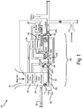
- FIG. 1 is a schematic of environmental control system 10.
- FIG. 1 shows environmental control system 10, air inlet 12, primary heat exchanger 14, secondary heat exchanger 16, ram air inlet 18, ram air fan 20, ram air outlet 22, air cycle machine 24, compressor 26, first turbine 28, second turbine 30, shaft 32, reheater 34, condenser 36, and water collector 38.
- Environmental control system 10 can be mounted in an aircraft to supply conditioned air to the aircraft cabin at the proper temperature and pressure. Air is ingested into environmental control system 10 through air intake 12 and flows through a duct to primary heat exchanger 14. The air that enters air intake 12 can be compressed air that is bled off a gas turbine engine and/or compressed air from a dedicated cabin air compressor (not shown in FIG. 1 ).
- Primary heat exchanger 14 is connected to secondary heat exchanger 16.
- Primary heat exchanger 14 and secondary heat exchanger 16 are used to cool the compressed air that flows through environmental control system 10 using cooling ram air.
- Ram air is pulled into environmental control system 10 through ram air inlet 18 with ram air fan 20 during operation on the ground or air is forced into the system due to flight of the aircraft.
- the ram air flows across primary heat exchanger 14 and secondary heat exchanger 16 to cool the air that flows through primary heat exchanger 14 and secondary heat exchanger 16.
- the used ram air is then dumped overboard through ram air outlet 22.
- Air from air intake 12 is ducted to primary heat exchanger 14 where it is cooled with the ram air that is pulled across primary heat exchanger 14 with ram air fan 20.
- the cooled air from primary heat exchanger 14 then flows to air cycle machine 24.
- Air cycle machine 24 includes compressor 26, first turbine 28, and second turbine 30 that are all mounted to shaft 32.
- Ram air fan 20 also forms a part of air cycle machine 24 and is mounted to shaft 32.
- the cooled air from primary heat exchanger 14 first flows through compressor 26 of air cycle machine 24 from compressor inlet 26A to compressor outlet 26B.
- Compressor 26 includes a compressor rotor mounted to shaft 32 that is rotated with shaft 32 to further compress the air flowing through compressor 26 of air cycle machine 24.
- the compressed air from compressor 26 then flows to secondary heat exchanger 16 where it is further cooled with ram air that is pulled across secondary heat exchanger 16.
- the cooled air from secondary heat exchanger 16 then flows through a duct to reheater 34 and condenser 36.
- Reheater 34 mixes the cooled air with recirculated air from the aircraft cabin to heat the cooled air.
- Condenser 36 condenses the cooled air by lowering the air temperature.
- the reheated and condensed air then flows through a duct to water collector 38, which collects the condensed water out of the air.
- the air then flows from water collector 38 back through reheater 34.
- Air from reheater 34 then flows through first turbine 28 of air cycle machine 24 from first turbine inlet 28A to first turbine outlet 28B.
- First turbine 28 also includes a first turbine rotor mounted on shaft 32. Energy is extracted from the air expanding through first turbine 28 of air cycle machine 24 to drive shaft 32.
- Environmental control system 10 also includes a plurality of temperature and pressure sensors, as is well known in the art. The plurality of temperature and pressure sensors have been omitted from FIG. 1 for clarity.
- Environmental control system 10 further includes check valves located throughout environmental control system 10 to control the flow of air through environmental control system 10. Check valves are used in environmental control system 10 to ensure that the air moving through environmental control system 10 is flowing in the proper direction during various operating modes of environmental control system 10.
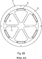
- FIG. 2A is a front view of prior art check valve 50.
- FIG. 2B is a front view of housing 52 of check valve 50.
- Check valve 50 is a prior art multi-flapper check valve.
- Check valve 50 includes housing 52, flappers 54, and hinges 56.
- Housing 52 includes rim 60, ribs 62, and openings 64.
- Flappers 54 each include end 70, first edge 72, and second edge 74. In FIG. 2B , in which only housing 52 is shown, flappers 54 are not present.
- Check valve 50 can be used in pneumatic systems, for example environmental control system 10 seen in FIG. 1 .
- Housing 52 forms a main body portion of check valve 50.
- Flappers 54 are attached to housing 52 with hinges 56.
- check valve 50 includes six flappers 54.
- Check valve 50 can include any suitable number of flappers 54 in alternate embodiments.
- Housing 52 includes rim 60, ribs 62, and openings 64.
- Rim 60 is a ring-shaped rim that forms an outer perimeter of housing 52.
- Ribs 62 extend from one side of rim 60 to a center of check valve 50 and act as center supports for housing 52 of check valve 50.
- the numbers of ribs 62 present in check valve 50 corresponds to the number of flappers 54 on check valve 50, thus there can be any suitable number of ribs 62 to correspond to the number of flappers 54 in alternate embodiments.
- Openings 64 are formed in housing 52 between rim 60 and ribs 62.
- the numbers of openings 64 present in check valve 50 corresponds to the number of flappers 54 on check valve 50, thus there can be any suitable number of openings 64 to correspond to the number of flappers 54 in alternate embodiments.
- Flappers 54 each include end 70, first edge 72, and second edge 74.
- Each flapper 54 is a triangular shape with two straight sides and a curved side. End 70 is the curved side of each flapper 54. End 70 of each flapper 54 is attached to one hinge 56 to attach each flapper 54 to housing 52.
- First edge 72 and second edge 74 are the straight sides of each flapper 54. First edge 72 and second edge 74 extend along ribs 62 of housing 52 when flappers 54 are positioned on housing 52 of check valve 50. First edge 72 and second edge 74 of each flapper 54 seal against ribs 62 of housing 52.
- Check valve 50 can be positioned in a pneumatic system. Check valve 50 opens and closes due to changes in an air pressure differential between an inlet of check vale 50 and an outlet of check valve 50. In a closed position, first edge 72 and second edge 74 of each flapper 54 are sealed against ribs 62 of housing 52 and each flapper 54 covers one opening 64 in housing 52. To open, ends 70 of flappers 54 rotate about hinges 56. This reveals openings 64 in housing 52. Air can then flow through openings 64 of housing 52, thus allowing air to flow through check valve 50. To close, ends 70 of flappers 54 will rotate along hinge 56 towards housing 52 and first edge 72 and second edge 74 of each flapper 54 will seal along ribs 62. Each flapper 54 will again be positioned over one opening 64 in housing 52. This closes check valve 50 and prevents air from moving through check valve 50.
- Check valve 50 as shown in FIGS. 2A-2B is a prior art check valve. As air flows through check valve 50, there is a pressure drop in the air moving through check valve 50 due to ribs 62. Ribs 62 of housing 52 extend across check valve 50 and impede the air as the air flows through check valve 50. This causes a drop in air pressure as the air flows through check valve 50. This drop in air pressure makes check valve 50 unsuitable for use in low pressure pneumatic systems.
- FIG. 3 is a front view of check valve 100.
- FIG. 4 is a cross-sectional side view of check valve 100, taken along line 4-4 of FIG. 3 .
- FIG. 5 is a front view of housing 102 of check valve 100.
- Check valve 100 includes housing 102, flappers 104, and hinges 106. Housing 102 includes rim 110 and opening 112. Flappers 104 each include end 120, first edge 122, second edge 124, and tab 126.
- Check valve 100 can be used in pneumatic systems, for example environmental control system 10 seen in FIG. 1 . More specifically, check valve 100 can be use in low pressure pneumatic systems. Housing 102 forms a main body portion of check valve 100. Flappers 104 are attached to housing 102 with hinges 106. In the embodiment shown in FIGS. 3-5 , check valve 100 includes six flappers 104. Check valve 100 can include any suitable number of flappers 104 in alternate embodiments.
- housing 102 includes rim 110 and opening 112.
- Rim 110 is a ring-shaped rim that forms an outer perimeter of housing 102.
- Opening 112 is a circular opening positioned inside of rim 110.
- Housing 102 does not have any ribs or flanges extending into opening 112 from rim 110.
- Hinges 106 are positioned on rim 110 of housing 102.
- flappers 104 each include end 120, first edge 122, second edge 124, and tab 126.
- Each flapper 104 is a triangular shape with two straight sides and a curved side. End 120 is the curved side of each flapper 104. End 120 of each flapper 104 is attached to one hinge 106 to attach each flapper 104 to housing 102.
- First edge 122 and second edge 124 are the straight sides of each flapper 104. First edge 122 of each flapper 104 overlaps with and seals against second edge 124 of an adjacent flapper 104.
- One tab 126 is connected to first edge 122 of each flapper 104.
- Tabs 126 are flanges that extend outward from first edge 122 of one flapper 104 and extend across second edge 124 of the adjacent flapper 104. Tabs 126 ensure that first edge 122 of each flapper 104 overlaps second edge 124 of the adjacent flapper 104.
- Check valve 100 can be positioned in a pneumatic system. Check valve 100 opens and closes due to changes in an air pressure differential between an inlet of check valve 100 and an outlet of check valve 100. In a closed position, first edge 122 of each flapper 104 seals against second edge 124 of the adjacent flapper 104 and tab 126 of each flapper 104 will fully overlap the adjacent flapper 104. This prevents air from moving through check valve 100.
- Check valve 100 opens when the air pressure reaches a certain level. To open, ends 120 of flappers 104 rotate about hinges 106. This reveals opening 112 in housing 102. Air can then flow through opening 112 of housing 102, thus allowing air to flow through check valve 100.
- ends 120 of flappers 104 will rotate along hinge 106 towards housing 102 and first edge 122 of each flapper 104 will overlap and seal against second edge 124 of the adjacent flapper 104. Flappers 104 will cover opening 112 in housing 102. This closes check valve 100 and prevents air from moving through check valve 100.
- Check valve 100 seen in FIGS. 3-5 is advantageous over the prior art valves of the type shown in FIGS. 2A-2B , as check valve 100 does not have any ribs extending across housing 102 of check valve 100. This creates a single opening 112 in housing 102 and prevents there from being a loss in pressure as air moves through check valve 100. This makes check valve 100 suitable for use in low pressure pneumatic systems because the loss in air pressure through housing 102 in check valve 100 is much lower than the loss in air pressure through housing 52 of prior art check valve 50 (seen in FIGS. 2A-2B ) for the same size valve. Check valve 100 can open when the pressure of the air on the downstream side is lower than the air pressure on the upstream side.
- Housing 102 of check valve 100 is simpler to design and manufacture, compared to prior art check valve 50 seen in FIGS. 2A-2B . Openings 64 in prior art check valve 50 had to be machined or otherwise manufactured into housing 52, which was time consuming and costly. Housing 102 of check valve 100 can be manufactured with opening 112, eliminating the need for machining or other manufacturing steps to create a number of smaller openings. This makes housing 102 of check valve 100 easier and most cost-efficient to manufacture. Housing 102 is also lower in weight compared to prior art housing 52, due to the elimination of the ribs.
- Flappers 104 of check valve 100 are responsible for both the sealing and load carrying capabilities of check valve 100, except at ends 120 where flappers 104 are attached to housing 102. Flappers 104 are loaded against first edge 122 and second edge 124. As seen in FIG. 4 , when check valve 100 is in a closed position, flappers 104 form a conical shape. First edge 122 of flappers 104 and second edge 124 of flappers 104 are designed so that first edge 122 overlaps second edge 124. This allows check valve 100 to seal without jamming. Tabs 126 on flappers 104 further prevent jamming, as tabs 126 ensure that first edge 122 overlaps second edge 124 as check valve 100 closes. Tabs 126 also prevent flappers 104 from getting misaligned or disengaging one another when check valve 100 is in an open position.
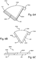
- FIG. 6A is a perspective view of flapper 104A.
- FIG. 6B is a front view of flapper 104A.
- FIG. 6C is a side view of flapper 104A.
- Flapper 104A includes end 120A, first edge 122A, second edge 124A, tab 126A, first lip 130, and second lip 132.
- Flapper 104A is a first embodiment of a flapper that can be used in check valve 100, as seen in FIGS. 3-5 .
- Flapper 104A is a stepped flapper that has stepped edges that overlap.
- Flapper 104A is a triangular shape with two straight sides and a curved side.
- End 120A is the curved side of flapper 104A and can be used to attached flapper 104A to check valve 100.
- First edge 122A and second edge 124A are the straight sides of flapper 104A that overlap and seal against one another when check valve 100 is in a closed position.
- Tab 126A is connected to first edge 122A of flapper 104A and extends away from flapper 104A.
- First edge 122A of flapper 104A has first lip 130 cut into it.
- First lip 130 is a step that is cut into a bottom side of flapper 104A.
- Second edge 124A of flapper 104A has second lip 132 cut into it.
- Second lip 132 is a step that is cut into a top side of flapper 104A.
- First lip 130 on first edge 122A is sized so that it fits with second lip 132 on second edge 124A. This allows first lip 130 on first edge 122A to seal with second lip 132 on second edge 124A.
- First lip 130 and second lip 132 on flapper 104A makes flapper 104A suitable for use in check valve 100, as seen in FIGS. 3-5 .
- Check valve 100 is suitable for use in low pressure pneumatic systems, as check valve 100 has flappers 104 that overlap and seal against one another.
- Flapper 104A has first lip 130 and second lip 132 so that first lip 130 on a first flapper 104A can overlap and seal against second lip 132 on an adjacent flapper 104A. This makes flapper 104A suitable for use on check valve 100.
Description
- The present disclosure relates to check valves. More specifically, the present disclosure relates to multi-flapper check valves for use in environmental control systems.
- Environmental control systems in aircraft condition air for delivery to an aircraft cabin. Conditioned air is air at a temperature, pressure, and humidity desirable for aircraft passenger comfort and safety. At or near ground level, the ambient air temperature and/or humidity is often sufficiently high that the air must be cooled as part of the conditioning process before being delivered to the aircraft cabin. At flight altitude, ambient air is often far cooler than desired, but at such a low pressure that it must be compressed to an acceptable pressure as part of the conditioning process. Compressing ambient air at flight altitude heats the resulting pressurized air sufficiently that it must be cooled, even if the initial ambient air temperature is very low. Thus, under most conditions, heat must be removed from air by the environmental control system before the air is delivered to the aircraft cabin. Environmental control systems can include air cycle machines that include a compressor section and at least one turbine section that can be used to cool and pressurize the air.
- Environmental control systems include check valves positioned throughout the system to allow air to flow in a first direction through the environmental control system and to prevent the air from flowing in a second direction through the environmental control system. In a closed position, check valves prevent air from moving through the environmental control system. Once the pressure of the air in the system reaches a certain level, the check valve opens to allow air to flow through the system. In this manner, check valves can regulate how air moves through the environmental control system based on the pressure of the air in the system.
- A multi-flapper check valve having the features of the preamble of claim 1 is disclosed in
US 6035896 A . Other multi-flapper check valves are disclosed inUS 4209037 A ,DE 202007017181 A ,US 2011/0056569 A1 andWO2004/055338 A1 . - According to the invention, there is provided a multi-flapper check valve as set forth in claim 1 .
- Also provided is an environmental control system as set forth in claim 7.
- Also provided is a method as set forth in claim 9.
- Features of embodiments of the invention are set forth in the dependent claims.
-
-
FIG. 1 is a schematic of an environmental control system. -
FIG. 2A is a front view of a prior art multi-flapper check valve. -
FIG. 2B is a front view of a housing of the prior art multi-flapper check valve. -
FIG. 3 is a front view of a multi-flapper check valve. -
FIG. 4 is a cross-sectional side view of the multi-flapper check valve, taken along line 4-4 ofFIG. 3 . -
FIG. 5 is a front view of a housing of the multi-flapper check valve. -
FIG. 6A is a perspective view of a first embodiment of a flapper. -
FIG. 6B is a front view of the first embodiment of the flapper. -
FIG. 6C is a side view of the first embodiment of the flapper. -
FIG. 1 is a schematic ofenvironmental control system 10.FIG. 1 showsenvironmental control system 10,air inlet 12,primary heat exchanger 14,secondary heat exchanger 16,ram air inlet 18,ram air fan 20,ram air outlet 22,air cycle machine 24,compressor 26,first turbine 28,second turbine 30,shaft 32,reheater 34,condenser 36, andwater collector 38. -
Environmental control system 10 can be mounted in an aircraft to supply conditioned air to the aircraft cabin at the proper temperature and pressure. Air is ingested intoenvironmental control system 10 throughair intake 12 and flows through a duct toprimary heat exchanger 14. The air that entersair intake 12 can be compressed air that is bled off a gas turbine engine and/or compressed air from a dedicated cabin air compressor (not shown inFIG. 1 ). -
Primary heat exchanger 14 is connected tosecondary heat exchanger 16.Primary heat exchanger 14 andsecondary heat exchanger 16 are used to cool the compressed air that flows throughenvironmental control system 10 using cooling ram air. Ram air is pulled intoenvironmental control system 10 throughram air inlet 18 withram air fan 20 during operation on the ground or air is forced into the system due to flight of the aircraft. The ram air flows acrossprimary heat exchanger 14 andsecondary heat exchanger 16 to cool the air that flows throughprimary heat exchanger 14 andsecondary heat exchanger 16. The used ram air is then dumped overboard throughram air outlet 22. - Air from
air intake 12 is ducted toprimary heat exchanger 14 where it is cooled with the ram air that is pulled acrossprimary heat exchanger 14 withram air fan 20. The cooled air fromprimary heat exchanger 14 then flows toair cycle machine 24.Air cycle machine 24 includescompressor 26,first turbine 28, andsecond turbine 30 that are all mounted toshaft 32. Ramair fan 20 also forms a part ofair cycle machine 24 and is mounted toshaft 32. The cooled air fromprimary heat exchanger 14 first flows throughcompressor 26 ofair cycle machine 24 fromcompressor inlet 26A tocompressor outlet 26B.Compressor 26 includes a compressor rotor mounted toshaft 32 that is rotated withshaft 32 to further compress the air flowing throughcompressor 26 ofair cycle machine 24. The compressed air fromcompressor 26 then flows tosecondary heat exchanger 16 where it is further cooled with ram air that is pulled acrosssecondary heat exchanger 16. - The cooled air from
secondary heat exchanger 16 then flows through a duct toreheater 34 and condenser 36. Reheater 34 mixes the cooled air with recirculated air from the aircraft cabin to heat the cooled air.Condenser 36 condenses the cooled air by lowering the air temperature. The reheated and condensed air then flows through a duct towater collector 38, which collects the condensed water out of the air. The air then flows fromwater collector 38 back throughreheater 34. Air fromreheater 34 then flows throughfirst turbine 28 ofair cycle machine 24 fromfirst turbine inlet 28A tofirst turbine outlet 28B.First turbine 28 also includes a first turbine rotor mounted onshaft 32. Energy is extracted from the air expanding throughfirst turbine 28 ofair cycle machine 24 to driveshaft 32. - Air from
first turbine 28 then flows back throughcondenser 36. Air fromcondenser 36 then flows throughsecond turbine 30 ofair cycle machine 24 fromsecond turbine inlet 30A tosecond turbine outlet 30B.Second turbine 30 also includes a second turbine rotor mounted onshaft 32. Energy is extracted from the air expanding throughsecond turbine 30 ofair cycle machine 24 to driveshaft 32. Air fromsecond turbine 30 then flows out ofair cycle machine 24 to be delivered to the aircraft cabin. -
Environmental control system 10 also includes a plurality of temperature and pressure sensors, as is well known in the art. The plurality of temperature and pressure sensors have been omitted fromFIG. 1 for clarity.Environmental control system 10 further includes check valves located throughoutenvironmental control system 10 to control the flow of air throughenvironmental control system 10. Check valves are used inenvironmental control system 10 to ensure that the air moving throughenvironmental control system 10 is flowing in the proper direction during various operating modes ofenvironmental control system 10. -
FIG. 2A is a front view of priorart check valve 50.FIG. 2B is a front view ofhousing 52 ofcheck valve 50. Checkvalve 50 is a prior art multi-flapper check valve. Checkvalve 50 includeshousing 52,flappers 54, and hinges 56.Housing 52 includesrim 60,ribs 62, andopenings 64.Flappers 54 each includeend 70,first edge 72, andsecond edge 74. InFIG. 2B , in which onlyhousing 52 is shown,flappers 54 are not present. - Check
valve 50 can be used in pneumatic systems, for exampleenvironmental control system 10 seen inFIG. 1 .Housing 52 forms a main body portion ofcheck valve 50.Flappers 54 are attached tohousing 52 with hinges 56. In the embodiment shown inFIGS. 2A-2B ,check valve 50 includes sixflappers 54. Checkvalve 50 can include any suitable number offlappers 54 in alternate embodiments. -
Housing 52 includesrim 60,ribs 62, andopenings 64.Rim 60 is a ring-shaped rim that forms an outer perimeter ofhousing 52.Ribs 62 extend from one side ofrim 60 to a center ofcheck valve 50 and act as center supports forhousing 52 ofcheck valve 50. There are sixribs 62 in the embodiment shown inFIGS. 2A-2B . The numbers ofribs 62 present incheck valve 50 corresponds to the number offlappers 54 oncheck valve 50, thus there can be any suitable number ofribs 62 to correspond to the number offlappers 54 in alternate embodiments.Openings 64 are formed inhousing 52 betweenrim 60 andribs 62. There are sixopenings 64 in the embodiment shown inFIGS. 2A-2B . The numbers ofopenings 64 present incheck valve 50 corresponds to the number offlappers 54 oncheck valve 50, thus there can be any suitable number ofopenings 64 to correspond to the number offlappers 54 in alternate embodiments. -
Flappers 54 each includeend 70,first edge 72, andsecond edge 74. Eachflapper 54 is a triangular shape with two straight sides and a curved side.End 70 is the curved side of eachflapper 54.End 70 of eachflapper 54 is attached to onehinge 56 to attach eachflapper 54 tohousing 52.First edge 72 andsecond edge 74 are the straight sides of eachflapper 54.First edge 72 andsecond edge 74 extend alongribs 62 ofhousing 52 whenflappers 54 are positioned onhousing 52 ofcheck valve 50.First edge 72 andsecond edge 74 of eachflapper 54 seal againstribs 62 ofhousing 52. - Check
valve 50 can be positioned in a pneumatic system. Checkvalve 50 opens and closes due to changes in an air pressure differential between an inlet ofcheck vale 50 and an outlet ofcheck valve 50. In a closed position,first edge 72 andsecond edge 74 of eachflapper 54 are sealed againstribs 62 ofhousing 52 and eachflapper 54 covers oneopening 64 inhousing 52. To open, ends 70 offlappers 54 rotate about hinges 56. This revealsopenings 64 inhousing 52. Air can then flow throughopenings 64 ofhousing 52, thus allowing air to flow throughcheck valve 50. To close, ends 70 offlappers 54 will rotate alonghinge 56 towardshousing 52 andfirst edge 72 andsecond edge 74 of eachflapper 54 will seal alongribs 62. Eachflapper 54 will again be positioned over oneopening 64 inhousing 52. This closescheck valve 50 and prevents air from moving throughcheck valve 50. - Check
valve 50 as shown inFIGS. 2A-2B is a prior art check valve. As air flows throughcheck valve 50, there is a pressure drop in the air moving throughcheck valve 50 due toribs 62.Ribs 62 ofhousing 52 extend acrosscheck valve 50 and impede the air as the air flows throughcheck valve 50. This causes a drop in air pressure as the air flows throughcheck valve 50. This drop in air pressure makescheck valve 50 unsuitable for use in low pressure pneumatic systems. -
FIG. 3 is a front view ofcheck valve 100.FIG. 4 is a cross-sectional side view ofcheck valve 100, taken along line 4-4 ofFIG. 3 .FIG. 5 is a front view ofhousing 102 ofcheck valve 100.Check valve 100 includeshousing 102,flappers 104, and hinges 106.Housing 102 includesrim 110 andopening 112.Flappers 104 each includeend 120,first edge 122,second edge 124, andtab 126. -
Check valve 100 can be used in pneumatic systems, for exampleenvironmental control system 10 seen inFIG. 1 . More specifically,check valve 100 can be use in low pressure pneumatic systems.Housing 102 forms a main body portion ofcheck valve 100.Flappers 104 are attached tohousing 102 withhinges 106. In the embodiment shown inFIGS. 3-5 ,check valve 100 includes sixflappers 104.Check valve 100 can include any suitable number offlappers 104 in alternate embodiments. - As seen in
FIG. 5 ,housing 102 includesrim 110 andopening 112.Rim 110 is a ring-shaped rim that forms an outer perimeter ofhousing 102.Opening 112 is a circular opening positioned inside ofrim 110.Housing 102 does not have any ribs or flanges extending into opening 112 fromrim 110.Hinges 106 are positioned onrim 110 ofhousing 102. - As shown in
FIGS. 3 and4 ,flappers 104 each includeend 120,first edge 122,second edge 124, andtab 126. Eachflapper 104 is a triangular shape with two straight sides and a curved side.End 120 is the curved side of eachflapper 104.End 120 of eachflapper 104 is attached to onehinge 106 to attach eachflapper 104 tohousing 102.First edge 122 andsecond edge 124 are the straight sides of eachflapper 104. First edge 122 of eachflapper 104 overlaps with and seals againstsecond edge 124 of anadjacent flapper 104. Onetab 126 is connected tofirst edge 122 of eachflapper 104.Tabs 126 are flanges that extend outward fromfirst edge 122 of oneflapper 104 and extend acrosssecond edge 124 of theadjacent flapper 104.Tabs 126 ensure thatfirst edge 122 of eachflapper 104 overlapssecond edge 124 of theadjacent flapper 104. -
Check valve 100 can be positioned in a pneumatic system.Check valve 100 opens and closes due to changes in an air pressure differential between an inlet ofcheck valve 100 and an outlet ofcheck valve 100. In a closed position,first edge 122 of eachflapper 104 seals againstsecond edge 124 of theadjacent flapper 104 andtab 126 of eachflapper 104 will fully overlap theadjacent flapper 104. This prevents air from moving throughcheck valve 100.Check valve 100 opens when the air pressure reaches a certain level. To open, ends 120 offlappers 104 rotate abouthinges 106. This reveals opening 112 inhousing 102. Air can then flow through opening 112 ofhousing 102, thus allowing air to flow throughcheck valve 100. To close, ends 120 offlappers 104 will rotate alonghinge 106 towardshousing 102 andfirst edge 122 of eachflapper 104 will overlap and seal againstsecond edge 124 of theadjacent flapper 104.Flappers 104 will cover opening 112 inhousing 102. This closescheck valve 100 and prevents air from moving throughcheck valve 100. -
Check valve 100 seen inFIGS. 3-5 is advantageous over the prior art valves of the type shown inFIGS. 2A-2B , ascheck valve 100 does not have any ribs extending acrosshousing 102 ofcheck valve 100. This creates asingle opening 112 inhousing 102 and prevents there from being a loss in pressure as air moves throughcheck valve 100. This makescheck valve 100 suitable for use in low pressure pneumatic systems because the loss in air pressure throughhousing 102 incheck valve 100 is much lower than the loss in air pressure throughhousing 52 of prior art check valve 50 (seen inFIGS. 2A-2B ) for the same size valve.Check valve 100 can open when the pressure of the air on the downstream side is lower than the air pressure on the upstream side. -
Housing 102 ofcheck valve 100 is simpler to design and manufacture, compared to priorart check valve 50 seen inFIGS. 2A-2B .Openings 64 in priorart check valve 50 had to be machined or otherwise manufactured intohousing 52, which was time consuming and costly.Housing 102 ofcheck valve 100 can be manufactured withopening 112, eliminating the need for machining or other manufacturing steps to create a number of smaller openings. This makeshousing 102 ofcheck valve 100 easier and most cost-efficient to manufacture.Housing 102 is also lower in weight compared toprior art housing 52, due to the elimination of the ribs. -
Flappers 104 ofcheck valve 100 are responsible for both the sealing and load carrying capabilities ofcheck valve 100, except at ends 120 whereflappers 104 are attached tohousing 102.Flappers 104 are loaded againstfirst edge 122 andsecond edge 124. As seen inFIG. 4 , whencheck valve 100 is in a closed position,flappers 104 form a conical shape. First edge 122 offlappers 104 andsecond edge 124 offlappers 104 are designed so thatfirst edge 122 overlapssecond edge 124. This allowscheck valve 100 to seal without jamming.Tabs 126 onflappers 104 further prevent jamming, astabs 126 ensure thatfirst edge 122 overlapssecond edge 124 ascheck valve 100 closes.Tabs 126 also preventflappers 104 from getting misaligned or disengaging one another whencheck valve 100 is in an open position. -
FIG. 6A is a perspective view offlapper 104A.FIG. 6B is a front view offlapper 104A.FIG. 6C is a side view offlapper 104A.Flapper 104A includesend 120A,first edge 122A,second edge 124A,tab 126A,first lip 130, andsecond lip 132. -
Flapper 104A is a first embodiment of a flapper that can be used incheck valve 100, as seen inFIGS. 3-5 .Flapper 104A is a stepped flapper that has stepped edges that overlap.Flapper 104A is a triangular shape with two straight sides and a curved side.End 120A is the curved side offlapper 104A and can be used to attachedflapper 104A to checkvalve 100. First edge 122A andsecond edge 124A are the straight sides offlapper 104A that overlap and seal against one another whencheck valve 100 is in a closed position.Tab 126A is connected tofirst edge 122A offlapper 104A and extends away fromflapper 104A. -
First edge 122A offlapper 104A hasfirst lip 130 cut into it.First lip 130 is a step that is cut into a bottom side offlapper 104A.Second edge 124A offlapper 104A hassecond lip 132 cut into it.Second lip 132 is a step that is cut into a top side offlapper 104A.First lip 130 onfirst edge 122A is sized so that it fits withsecond lip 132 onsecond edge 124A. This allowsfirst lip 130 onfirst edge 122A to seal withsecond lip 132 onsecond edge 124A. -
First lip 130 andsecond lip 132 onflapper 104A makesflapper 104A suitable for use incheck valve 100, as seen inFIGS. 3-5 .Check valve 100 is suitable for use in low pressure pneumatic systems, ascheck valve 100 hasflappers 104 that overlap and seal against one another.Flapper 104A hasfirst lip 130 andsecond lip 132 so thatfirst lip 130 on afirst flapper 104A can overlap and seal againstsecond lip 132 on anadjacent flapper 104A. This makesflapper 104A suitable for use oncheck valve 100. - While the invention has been described with reference to an exemplary embodiment(s), it will be understood by those skilled in the art that various changes may be made and equivalents may be substituted for elements thereof without departing from the scope of the invention. In addition, many modifications may be made to adapt a particular situation or material to the teachings of the invention without departing from the essential scope thereof. Therefore, it is intended that the invention not be limited to the particular embodiment(s) disclosed, but that the invention will include all embodiments falling within the scope of the appended claims.
Claims (13)
- A multi-flapper check valve (100) comprising:a housing (102) with an opening (112) surrounded by a ring-shaped rim (110);a plurality of flappers (104) wherein each flapper (104) has an end (120), a first edge (122) extending away from the end (120), a second edge (124) extending away from the end (120) and a tip at an intersection of the first edge (122) and the second edge (124); anda hinge (106) that connects the end of each flapper (104) to the rim (110) of the housing (102); characterized in that:when the multi-flapper check valve (100) is in a closed position, the first edge (122) of each flapper (104) overlaps and seals against the second edge (124) of an adjacent flapper (104) from the end of each flapper (104) to the tip of each flapper (104);wherein:
the first edge (122A) of the flapper (104A) has a lip (130) cut into a bottom portion of the flapper (104A); andthe second edge (122B) of the flapper (104A) has a lip (132) cut into a top portion of the flapper (104A). - The multi-flapper check valve (100) of claim 1, wherein when the multi-flapper check valve (100) is in a closed position, the plurality of flappers (104A, 104B) are configured to cover the opening (112) in the housing (102).
- The multi-flapper check valve (100) of claim 1 or 2, wherein when the multi-flapper check valve (100) is in an open position, each flapper (104A, 104B) is configured to rotate with the hinge (106) to uncover the opening (112) in the housing (102).
- The multi-flapper check valve (100) of any preceding claim, and further comprising:
a tab (126A) extending from the first edge (122A) of the flapper (104A), wherein the tab (126A) overlaps the adjacent flapper (104A). - The multi-flapper check valve (100) of any preceding claim, wherein there are six flappers (104A) on the multi-flapper check valve (100).
- The multi-flapper check valve (100) of any preceding claim, wherein there are no ribs extending across the opening (112) in the housing (102).
- An environmental control system (10) comprising:a rotary machine comprising:a compressor section with a compressor rotor; anda turbine section with a turbine rotor; anda check valve (100) according to any preceding claim in the rotary machine,wherein when the check valve (100) is in a closed position, the plurality of flappers (104) are configured to prevent air from flowing through the rotary machine; andwherein when the check valve (100) is in an open position, the plurality of flappers (104) are configured to uncover the opening (112) in the housing (102) of the check valve (100).
- The environmental control system (10) of claim 7, wherein when the check valve (100) is in a closed position, the plurality of flappers are configured to seal against one another to cover the opening (112) in the housing (102) of the check valve (100).
- A method comprising:flowing air through a rotary machine; andcontrolling the flow of air through the rotary machine with a check valve (100) as defined in claim 1.
- The method of claim 9, wherein the check valve (100) can be moved between an open and closed position by rotating the flappers (104) of the check valve (100) around the hinge (106) that connects the flappers to the rim (110) of the housing (102).
- The method of claim 10, wherein moving the check valve (100) to the open position unseals the first edge (122) of each flapper (104) from the second edge (124) of the adjacent flapper (104) and uncovers the opening (112) in the housing (102) of the check valve (100).
- The method of claim 9, 10 or 11, wherein there are no ribs extending across the opening (112) in the housing (102).
- The method of any of claims 9 to 12, wherein the check valve (100) further comprises:
a tab (126) extending from the first edge (122) of each flapper (104).
Applications Claiming Priority (1)
| Application Number | Priority Date | Filing Date | Title |
|---|---|---|---|
| US14/742,121 US10487740B2 (en) | 2015-06-17 | 2015-06-17 | Multi-flapper check valve without center supports |
Publications (2)
| Publication Number | Publication Date |
|---|---|
| EP3106721A1 EP3106721A1 (en) | 2016-12-21 |
| EP3106721B1 true EP3106721B1 (en) | 2020-06-10 |
Family
ID=56148196
Family Applications (1)
| Application Number | Title | Priority Date | Filing Date |
|---|---|---|---|
| EP16175071.6A Active EP3106721B1 (en) | 2015-06-17 | 2016-06-17 | Multi-flapper check valve without center supports |
Country Status (2)
| Country | Link |
|---|---|
| US (1) | US10487740B2 (en) |
| EP (1) | EP3106721B1 (en) |
Families Citing this family (6)
| Publication number | Priority date | Publication date | Assignee | Title |
|---|---|---|---|---|
| EP3181965B1 (en) | 2015-12-14 | 2020-04-22 | Hamilton Sundstrand Corporation | Check valve |
| EP3660366B1 (en) | 2018-11-27 | 2021-09-29 | Hamilton Sundstrand Corporation | Check valves |
| DE102019000611A1 (en) * | 2019-01-28 | 2020-07-30 | M. Mohsen Saadat | Artificial heart |
| CN111498158A (en) * | 2020-05-11 | 2020-08-07 | 孟辉 | Automatic change control material bagging-off assembly line |
| US11808290B1 (en) * | 2020-12-18 | 2023-11-07 | University Of South Florida | Fluid flow conditioning apparatus |
| US11828372B2 (en) | 2022-03-31 | 2023-11-28 | General Electric Company | Check valve assembly |
Family Cites Families (16)
| Publication number | Priority date | Publication date | Assignee | Title |
|---|---|---|---|---|
| US3118467A (en) | 1961-02-23 | 1964-01-21 | Kuhn John | Automatic check valve |
| US3483824A (en) | 1967-09-15 | 1969-12-16 | Babcock & Wilcox Co | Rotary pump with check valve |
| US4209037A (en) | 1977-11-25 | 1980-06-24 | Aeroquip Corporation | Environmental check valve |
| US4406022A (en) | 1981-11-16 | 1983-09-27 | Kathryn Roy | Prosthetic valve means for cardiovascular surgery |
| US4458876A (en) * | 1982-09-16 | 1984-07-10 | Ventre Corporation | Annular blowout preventer |
| US5078739A (en) | 1990-07-20 | 1992-01-07 | Janus Biomedical, Inc. | Bileaflet heart valve with external leaflets |
| US5628792A (en) | 1992-03-13 | 1997-05-13 | Jcl Technic Ab | Cardiac valve with recessed valve flap hinges |
| US6035896A (en) * | 1995-09-01 | 2000-03-14 | Varioraw Percutive S.A. | Valve |
| US6174232B1 (en) * | 1999-09-07 | 2001-01-16 | International Business Machines Corporation | Helically conforming axial fan check valve |
| US6851255B2 (en) * | 2002-12-18 | 2005-02-08 | Pratt & Whitney Canada Corp. | Normally open reverse flow flapper valve |
| TW572187U (en) * | 2003-04-24 | 2004-01-11 | Datech Technology Co Ltd | Register incorporationg a toggle-joint mechanism between open and closed position |
| DE202007017181U1 (en) | 2007-12-08 | 2008-02-28 | Norma Germany Gmbh | Coupling for connecting two cooling system sections |
| US8616944B2 (en) | 2009-09-04 | 2013-12-31 | GM Global Technology Operations LLC | Pressure relief valve for a vehicle body |
| IT1402918B1 (en) * | 2010-12-06 | 2013-09-27 | Mib Italiana Spa | CONTROL VALVE FOR SEPARABLE CONNECTION UNITS FOR FLEXIBLE PIPES. |
| US8387950B2 (en) * | 2011-04-06 | 2013-03-05 | General Electric Company | Flow device and method and system using the flow device |
| US8714034B2 (en) * | 2011-08-03 | 2014-05-06 | Colorado State University Research Foundation | Gas flux measurement using traps |
-
2015
- 2015-06-17 US US14/742,121 patent/US10487740B2/en active Active
-
2016
- 2016-06-17 EP EP16175071.6A patent/EP3106721B1/en active Active
Non-Patent Citations (1)
| Title |
|---|
| None * |
Also Published As
| Publication number | Publication date |
|---|---|
| EP3106721A1 (en) | 2016-12-21 |
| US10487740B2 (en) | 2019-11-26 |
| US20160369696A1 (en) | 2016-12-22 |
Similar Documents
| Publication | Publication Date | Title |
|---|---|---|
| EP3106721B1 (en) | Multi-flapper check valve without center supports | |
| EP2942277B1 (en) | Environmental control system with air cycle machine bypass shutoff valves | |
| EP2602191B1 (en) | Motor driven cabin air compressor with variable diffuser | |
| US8092153B2 (en) | Bypass air scoop for gas turbine engine | |
| EP3084183B1 (en) | Heat exchanger flow control assembly and corresponding method | |
| US9476362B2 (en) | Turbomachine with bleed valves located at the intermediate case | |
| US11073090B2 (en) | Valved airflow passage assembly for adjusting airflow distortion in gas turbine engine | |
| US9022843B2 (en) | Outlet valve for an airplane | |
| JP3837166B2 (en) | Integrated bypass valve and air circulation machine | |
| US20120114463A1 (en) | Motor driven cabin air compressor with variable diffuser | |
| US9777633B1 (en) | Secondary airflow passage for adjusting airflow distortion in gas turbine engine | |
| EP1998027B1 (en) | Gas turbine engine comprising a nacelle compartment plenum for bleed air flow delivery system | |
| EP2932068B1 (en) | Gas turbine engine with cooling scheme for drive gear system and pitch control | |
| EP3427809B1 (en) | Water extractor | |
| US9932847B2 (en) | Guide blade for a gas turbine | |
| CN104847422A (en) | First stage turbine housing for an air cycle machine | |
| EP2378086A2 (en) | Variable turbine nozzle and valve | |
| EP1724444B1 (en) | Bypass air metering valve | |
| EP3508424B1 (en) | Fan and compressor housing for an air cycle machine | |
| EP3385171B1 (en) | Fan bypass and shutoff check valve | |
| EP4336050A1 (en) | Variable pipe diffuser | |
| CN113795657A (en) | Reversible exhaust structure |
Legal Events
| Date | Code | Title | Description |
|---|---|---|---|
| PUAI | Public reference made under article 153(3) epc to a published international application that has entered the european phase |
Free format text: ORIGINAL CODE: 0009012 |
|
| STAA | Information on the status of an ep patent application or granted ep patent |
Free format text: STATUS: THE APPLICATION HAS BEEN PUBLISHED |
|
| AK | Designated contracting states |
Kind code of ref document: A1 Designated state(s): AL AT BE BG CH CY CZ DE DK EE ES FI FR GB GR HR HU IE IS IT LI LT LU LV MC MK MT NL NO PL PT RO RS SE SI SK SM TR |
|
| AX | Request for extension of the european patent |
Extension state: BA ME |
|
| STAA | Information on the status of an ep patent application or granted ep patent |
Free format text: STATUS: REQUEST FOR EXAMINATION WAS MADE |
|
| 17P | Request for examination filed |
Effective date: 20170621 |
|
| RBV | Designated contracting states (corrected) |
Designated state(s): AL AT BE BG CH CY CZ DE DK EE ES FI FR GB GR HR HU IE IS IT LI LT LU LV MC MK MT NL NO PL PT RO RS SE SI SK SM TR |
|
| STAA | Information on the status of an ep patent application or granted ep patent |
Free format text: STATUS: EXAMINATION IS IN PROGRESS |
|
| 17Q | First examination report despatched |
Effective date: 20190701 |
|
| GRAP | Despatch of communication of intention to grant a patent |
Free format text: ORIGINAL CODE: EPIDOSNIGR1 |
|
| STAA | Information on the status of an ep patent application or granted ep patent |
Free format text: STATUS: GRANT OF PATENT IS INTENDED |
|
| INTG | Intention to grant announced |
Effective date: 20191219 |
|
| RIN1 | Information on inventor provided before grant (corrected) |
Inventor name: DEHAIS, JOHN M. |
|
| GRAS | Grant fee paid |
Free format text: ORIGINAL CODE: EPIDOSNIGR3 |
|
| GRAA | (expected) grant |
Free format text: ORIGINAL CODE: 0009210 |
|
| STAA | Information on the status of an ep patent application or granted ep patent |
Free format text: STATUS: THE PATENT HAS BEEN GRANTED |
|
| AK | Designated contracting states |
Kind code of ref document: B1 Designated state(s): AL AT BE BG CH CY CZ DE DK EE ES FI FR GB GR HR HU IE IS IT LI LT LU LV MC MK MT NL NO PL PT RO RS SE SI SK SM TR |
|
| REG | Reference to a national code |
Ref country code: GB Ref legal event code: FG4D |
|
| REG | Reference to a national code |
Ref country code: CH Ref legal event code: EP Ref country code: AT Ref legal event code: REF Ref document number: 1279453 Country of ref document: AT Kind code of ref document: T Effective date: 20200615 |
|
| REG | Reference to a national code |
Ref country code: DE Ref legal event code: R096 Ref document number: 602016037794 Country of ref document: DE |
|
| REG | Reference to a national code |
Ref country code: IE Ref legal event code: FG4D |
|
| REG | Reference to a national code |
Ref country code: LT Ref legal event code: MG4D |
|
| PG25 | Lapsed in a contracting state [announced via postgrant information from national office to epo] |
Ref country code: SE Free format text: LAPSE BECAUSE OF FAILURE TO SUBMIT A TRANSLATION OF THE DESCRIPTION OR TO PAY THE FEE WITHIN THE PRESCRIBED TIME-LIMIT Effective date: 20200610 Ref country code: FI Free format text: LAPSE BECAUSE OF FAILURE TO SUBMIT A TRANSLATION OF THE DESCRIPTION OR TO PAY THE FEE WITHIN THE PRESCRIBED TIME-LIMIT Effective date: 20200610 Ref country code: NO Free format text: LAPSE BECAUSE OF FAILURE TO SUBMIT A TRANSLATION OF THE DESCRIPTION OR TO PAY THE FEE WITHIN THE PRESCRIBED TIME-LIMIT Effective date: 20200910 Ref country code: GR Free format text: LAPSE BECAUSE OF FAILURE TO SUBMIT A TRANSLATION OF THE DESCRIPTION OR TO PAY THE FEE WITHIN THE PRESCRIBED TIME-LIMIT Effective date: 20200911 Ref country code: LT Free format text: LAPSE BECAUSE OF FAILURE TO SUBMIT A TRANSLATION OF THE DESCRIPTION OR TO PAY THE FEE WITHIN THE PRESCRIBED TIME-LIMIT Effective date: 20200610 |
|
| REG | Reference to a national code |
Ref country code: NL Ref legal event code: MP Effective date: 20200610 |
|
| PG25 | Lapsed in a contracting state [announced via postgrant information from national office to epo] |
Ref country code: RS Free format text: LAPSE BECAUSE OF FAILURE TO SUBMIT A TRANSLATION OF THE DESCRIPTION OR TO PAY THE FEE WITHIN THE PRESCRIBED TIME-LIMIT Effective date: 20200610 Ref country code: BG Free format text: LAPSE BECAUSE OF FAILURE TO SUBMIT A TRANSLATION OF THE DESCRIPTION OR TO PAY THE FEE WITHIN THE PRESCRIBED TIME-LIMIT Effective date: 20200910 Ref country code: LV Free format text: LAPSE BECAUSE OF FAILURE TO SUBMIT A TRANSLATION OF THE DESCRIPTION OR TO PAY THE FEE WITHIN THE PRESCRIBED TIME-LIMIT Effective date: 20200610 Ref country code: HR Free format text: LAPSE BECAUSE OF FAILURE TO SUBMIT A TRANSLATION OF THE DESCRIPTION OR TO PAY THE FEE WITHIN THE PRESCRIBED TIME-LIMIT Effective date: 20200610 |
|
| REG | Reference to a national code |
Ref country code: AT Ref legal event code: MK05 Ref document number: 1279453 Country of ref document: AT Kind code of ref document: T Effective date: 20200610 |
|
| PG25 | Lapsed in a contracting state [announced via postgrant information from national office to epo] |
Ref country code: NL Free format text: LAPSE BECAUSE OF FAILURE TO SUBMIT A TRANSLATION OF THE DESCRIPTION OR TO PAY THE FEE WITHIN THE PRESCRIBED TIME-LIMIT Effective date: 20200610 Ref country code: AL Free format text: LAPSE BECAUSE OF FAILURE TO SUBMIT A TRANSLATION OF THE DESCRIPTION OR TO PAY THE FEE WITHIN THE PRESCRIBED TIME-LIMIT Effective date: 20200610 |
|
| REG | Reference to a national code |
Ref country code: DE Ref legal event code: R119 Ref document number: 602016037794 Country of ref document: DE |
|
| PG25 | Lapsed in a contracting state [announced via postgrant information from national office to epo] |
Ref country code: RO Free format text: LAPSE BECAUSE OF FAILURE TO SUBMIT A TRANSLATION OF THE DESCRIPTION OR TO PAY THE FEE WITHIN THE PRESCRIBED TIME-LIMIT Effective date: 20200610 Ref country code: CZ Free format text: LAPSE BECAUSE OF FAILURE TO SUBMIT A TRANSLATION OF THE DESCRIPTION OR TO PAY THE FEE WITHIN THE PRESCRIBED TIME-LIMIT Effective date: 20200610 Ref country code: SM Free format text: LAPSE BECAUSE OF FAILURE TO SUBMIT A TRANSLATION OF THE DESCRIPTION OR TO PAY THE FEE WITHIN THE PRESCRIBED TIME-LIMIT Effective date: 20200610 Ref country code: IT Free format text: LAPSE BECAUSE OF FAILURE TO SUBMIT A TRANSLATION OF THE DESCRIPTION OR TO PAY THE FEE WITHIN THE PRESCRIBED TIME-LIMIT Effective date: 20200610 Ref country code: EE Free format text: LAPSE BECAUSE OF FAILURE TO SUBMIT A TRANSLATION OF THE DESCRIPTION OR TO PAY THE FEE WITHIN THE PRESCRIBED TIME-LIMIT Effective date: 20200610 Ref country code: AT Free format text: LAPSE BECAUSE OF FAILURE TO SUBMIT A TRANSLATION OF THE DESCRIPTION OR TO PAY THE FEE WITHIN THE PRESCRIBED TIME-LIMIT Effective date: 20200610 Ref country code: ES Free format text: LAPSE BECAUSE OF FAILURE TO SUBMIT A TRANSLATION OF THE DESCRIPTION OR TO PAY THE FEE WITHIN THE PRESCRIBED TIME-LIMIT Effective date: 20200610 Ref country code: PT Free format text: LAPSE BECAUSE OF FAILURE TO SUBMIT A TRANSLATION OF THE DESCRIPTION OR TO PAY THE FEE WITHIN THE PRESCRIBED TIME-LIMIT Effective date: 20201012 |
|
| REG | Reference to a national code |
Ref country code: CH Ref legal event code: PL |
|
| PG25 | Lapsed in a contracting state [announced via postgrant information from national office to epo] |
Ref country code: PL Free format text: LAPSE BECAUSE OF FAILURE TO SUBMIT A TRANSLATION OF THE DESCRIPTION OR TO PAY THE FEE WITHIN THE PRESCRIBED TIME-LIMIT Effective date: 20200610 Ref country code: SK Free format text: LAPSE BECAUSE OF FAILURE TO SUBMIT A TRANSLATION OF THE DESCRIPTION OR TO PAY THE FEE WITHIN THE PRESCRIBED TIME-LIMIT Effective date: 20200610 Ref country code: IS Free format text: LAPSE BECAUSE OF FAILURE TO SUBMIT A TRANSLATION OF THE DESCRIPTION OR TO PAY THE FEE WITHIN THE PRESCRIBED TIME-LIMIT Effective date: 20201010 |
|
| PG25 | Lapsed in a contracting state [announced via postgrant information from national office to epo] |
Ref country code: LU Free format text: LAPSE BECAUSE OF NON-PAYMENT OF DUE FEES Effective date: 20200617 Ref country code: MC Free format text: LAPSE BECAUSE OF FAILURE TO SUBMIT A TRANSLATION OF THE DESCRIPTION OR TO PAY THE FEE WITHIN THE PRESCRIBED TIME-LIMIT Effective date: 20200610 |
|
| PLBE | No opposition filed within time limit |
Free format text: ORIGINAL CODE: 0009261 |
|
| STAA | Information on the status of an ep patent application or granted ep patent |
Free format text: STATUS: NO OPPOSITION FILED WITHIN TIME LIMIT |
|
| REG | Reference to a national code |
Ref country code: BE Ref legal event code: MM Effective date: 20200630 |
|
| PG25 | Lapsed in a contracting state [announced via postgrant information from national office to epo] |
Ref country code: CH Free format text: LAPSE BECAUSE OF NON-PAYMENT OF DUE FEES Effective date: 20200630 Ref country code: DK Free format text: LAPSE BECAUSE OF FAILURE TO SUBMIT A TRANSLATION OF THE DESCRIPTION OR TO PAY THE FEE WITHIN THE PRESCRIBED TIME-LIMIT Effective date: 20200610 Ref country code: LI Free format text: LAPSE BECAUSE OF NON-PAYMENT OF DUE FEES Effective date: 20200630 Ref country code: IE Free format text: LAPSE BECAUSE OF NON-PAYMENT OF DUE FEES Effective date: 20200617 |
|
| 26N | No opposition filed |
Effective date: 20210311 |
|
| PG25 | Lapsed in a contracting state [announced via postgrant information from national office to epo] |
Ref country code: BE Free format text: LAPSE BECAUSE OF NON-PAYMENT OF DUE FEES Effective date: 20200630 Ref country code: DE Free format text: LAPSE BECAUSE OF NON-PAYMENT OF DUE FEES Effective date: 20210101 Ref country code: SI Free format text: LAPSE BECAUSE OF FAILURE TO SUBMIT A TRANSLATION OF THE DESCRIPTION OR TO PAY THE FEE WITHIN THE PRESCRIBED TIME-LIMIT Effective date: 20200610 |
|
| PG25 | Lapsed in a contracting state [announced via postgrant information from national office to epo] |
Ref country code: TR Free format text: LAPSE BECAUSE OF FAILURE TO SUBMIT A TRANSLATION OF THE DESCRIPTION OR TO PAY THE FEE WITHIN THE PRESCRIBED TIME-LIMIT Effective date: 20200610 Ref country code: MT Free format text: LAPSE BECAUSE OF FAILURE TO SUBMIT A TRANSLATION OF THE DESCRIPTION OR TO PAY THE FEE WITHIN THE PRESCRIBED TIME-LIMIT Effective date: 20200610 Ref country code: CY Free format text: LAPSE BECAUSE OF FAILURE TO SUBMIT A TRANSLATION OF THE DESCRIPTION OR TO PAY THE FEE WITHIN THE PRESCRIBED TIME-LIMIT Effective date: 20200610 |
|
| PG25 | Lapsed in a contracting state [announced via postgrant information from national office to epo] |
Ref country code: MK Free format text: LAPSE BECAUSE OF FAILURE TO SUBMIT A TRANSLATION OF THE DESCRIPTION OR TO PAY THE FEE WITHIN THE PRESCRIBED TIME-LIMIT Effective date: 20200610 |
|
| P01 | Opt-out of the competence of the unified patent court (upc) registered |
Effective date: 20230522 |
|
| PGFP | Annual fee paid to national office [announced via postgrant information from national office to epo] |
Ref country code: FR Payment date: 20230523 Year of fee payment: 8 |
|
| PGFP | Annual fee paid to national office [announced via postgrant information from national office to epo] |
Ref country code: GB Payment date: 20230523 Year of fee payment: 8 |