EP1724444B1 - Bypass air metering valve - Google Patents
Bypass air metering valve Download PDFInfo
- Publication number
- EP1724444B1 EP1724444B1 EP06251066.4A EP06251066A EP1724444B1 EP 1724444 B1 EP1724444 B1 EP 1724444B1 EP 06251066 A EP06251066 A EP 06251066A EP 1724444 B1 EP1724444 B1 EP 1724444B1
- Authority
- EP
- European Patent Office
- Prior art keywords
- metering
- bushing
- metering valve
- valve according
- slots
- Prior art date
- Legal status (The legal status is an assumption and is not a legal conclusion. Google has not performed a legal analysis and makes no representation as to the accuracy of the status listed.)
- Active
Links
- 239000000463 material Substances 0.000 claims description 6
- 239000012530 fluid Substances 0.000 claims description 5
- 125000006850 spacer group Chemical group 0.000 claims description 4
- 239000002783 friction material Substances 0.000 claims description 3
- 229920000049 Carbon (fiber) Polymers 0.000 claims description 2
- 239000004917 carbon fiber Substances 0.000 claims description 2
- VNWKTOKETHGBQD-UHFFFAOYSA-N methane Chemical compound C VNWKTOKETHGBQD-UHFFFAOYSA-N 0.000 claims description 2
- 239000011347 resin Substances 0.000 claims description 2
- 229920005989 resin Polymers 0.000 claims description 2
- 229920001187 thermosetting polymer Polymers 0.000 claims description 2
- 238000001816 cooling Methods 0.000 description 3
- 239000012809 cooling fluid Substances 0.000 description 3
- 238000000034 method Methods 0.000 description 2
- 241000237503 Pectinidae Species 0.000 description 1
- 230000001276 controlling effect Effects 0.000 description 1
- 230000002708 enhancing effect Effects 0.000 description 1
- 238000009434 installation Methods 0.000 description 1
- 239000002184 metal Substances 0.000 description 1
- 230000001105 regulatory effect Effects 0.000 description 1
- 235000020637 scallop Nutrition 0.000 description 1
- 230000003068 static effect Effects 0.000 description 1
- 238000011144 upstream manufacturing Methods 0.000 description 1
- 238000009423 ventilation Methods 0.000 description 1
Images
Classifications
-
- F—MECHANICAL ENGINEERING; LIGHTING; HEATING; WEAPONS; BLASTING
- F01—MACHINES OR ENGINES IN GENERAL; ENGINE PLANTS IN GENERAL; STEAM ENGINES
- F01D—NON-POSITIVE DISPLACEMENT MACHINES OR ENGINES, e.g. STEAM TURBINES
- F01D17/00—Regulating or controlling by varying flow
- F01D17/10—Final actuators
- F01D17/12—Final actuators arranged in stator parts
- F01D17/14—Final actuators arranged in stator parts varying effective cross-sectional area of nozzles or guide conduits
- F01D17/141—Final actuators arranged in stator parts varying effective cross-sectional area of nozzles or guide conduits by means of shiftable members or valves obturating part of the flow path
-
- B—PERFORMING OPERATIONS; TRANSPORTING
- B01—PHYSICAL OR CHEMICAL PROCESSES OR APPARATUS IN GENERAL
- B01D—SEPARATION
- B01D46/00—Filters or filtering processes specially modified for separating dispersed particles from gases or vapours
- B01D46/0002—Casings; Housings; Frame constructions
- B01D46/0005—Mounting of filtering elements within casings, housings or frames
-
- B—PERFORMING OPERATIONS; TRANSPORTING
- B01—PHYSICAL OR CHEMICAL PROCESSES OR APPARATUS IN GENERAL
- B01D—SEPARATION
- B01D46/00—Filters or filtering processes specially modified for separating dispersed particles from gases or vapours
- B01D46/0039—Filters or filtering processes specially modified for separating dispersed particles from gases or vapours with flow guiding by feed or discharge devices
-
- B—PERFORMING OPERATIONS; TRANSPORTING
- B01—PHYSICAL OR CHEMICAL PROCESSES OR APPARATUS IN GENERAL
- B01D—SEPARATION
- B01D46/00—Filters or filtering processes specially modified for separating dispersed particles from gases or vapours
- B01D46/42—Auxiliary equipment or operation thereof
- B01D46/4227—Manipulating filters or filter elements, e.g. handles or extracting tools
-
- B—PERFORMING OPERATIONS; TRANSPORTING
- B01—PHYSICAL OR CHEMICAL PROCESSES OR APPARATUS IN GENERAL
- B01D—SEPARATION
- B01D46/00—Filters or filtering processes specially modified for separating dispersed particles from gases or vapours
- B01D46/42—Auxiliary equipment or operation thereof
- B01D46/4254—Allowing or improving visual supervision, e.g. lamps, transparent parts, windows
-
- F—MECHANICAL ENGINEERING; LIGHTING; HEATING; WEAPONS; BLASTING
- F02—COMBUSTION ENGINES; HOT-GAS OR COMBUSTION-PRODUCT ENGINE PLANTS
- F02C—GAS-TURBINE PLANTS; AIR INTAKES FOR JET-PROPULSION PLANTS; CONTROLLING FUEL SUPPLY IN AIR-BREATHING JET-PROPULSION PLANTS
- F02C6/00—Plural gas-turbine plants; Combinations of gas-turbine plants with other apparatus; Adaptations of gas- turbine plants for special use
- F02C6/04—Gas-turbine plants providing heated or pressurised working fluid for other apparatus, e.g. without mechanical power output
- F02C6/06—Gas-turbine plants providing heated or pressurised working fluid for other apparatus, e.g. without mechanical power output providing compressed gas
- F02C6/08—Gas-turbine plants providing heated or pressurised working fluid for other apparatus, e.g. without mechanical power output providing compressed gas the gas being bled from the gas-turbine compressor
-
- F—MECHANICAL ENGINEERING; LIGHTING; HEATING; WEAPONS; BLASTING
- F02—COMBUSTION ENGINES; HOT-GAS OR COMBUSTION-PRODUCT ENGINE PLANTS
- F02C—GAS-TURBINE PLANTS; AIR INTAKES FOR JET-PROPULSION PLANTS; CONTROLLING FUEL SUPPLY IN AIR-BREATHING JET-PROPULSION PLANTS
- F02C7/00—Features, components parts, details or accessories, not provided for in, or of interest apart form groups F02C1/00 - F02C6/00; Air intakes for jet-propulsion plants
- F02C7/12—Cooling of plants
-
- F—MECHANICAL ENGINEERING; LIGHTING; HEATING; WEAPONS; BLASTING
- F02—COMBUSTION ENGINES; HOT-GAS OR COMBUSTION-PRODUCT ENGINE PLANTS
- F02C—GAS-TURBINE PLANTS; AIR INTAKES FOR JET-PROPULSION PLANTS; CONTROLLING FUEL SUPPLY IN AIR-BREATHING JET-PROPULSION PLANTS
- F02C9/00—Controlling gas-turbine plants; Controlling fuel supply in air- breathing jet-propulsion plants
- F02C9/16—Control of working fluid flow
- F02C9/18—Control of working fluid flow by bleeding, bypassing or acting on variable working fluid interconnections between turbines or compressors or their stages
-
- F—MECHANICAL ENGINEERING; LIGHTING; HEATING; WEAPONS; BLASTING
- F05—INDEXING SCHEMES RELATING TO ENGINES OR PUMPS IN VARIOUS SUBCLASSES OF CLASSES F01-F04
- F05D—INDEXING SCHEME FOR ASPECTS RELATING TO NON-POSITIVE-DISPLACEMENT MACHINES OR ENGINES, GAS-TURBINES OR JET-PROPULSION PLANTS
- F05D2250/00—Geometry
- F05D2250/40—Movement of components
- F05D2250/41—Movement of components with one degree of freedom
- F05D2250/411—Movement of components with one degree of freedom in rotation
-
- F—MECHANICAL ENGINEERING; LIGHTING; HEATING; WEAPONS; BLASTING
- F05—INDEXING SCHEMES RELATING TO ENGINES OR PUMPS IN VARIOUS SUBCLASSES OF CLASSES F01-F04
- F05D—INDEXING SCHEME FOR ASPECTS RELATING TO NON-POSITIVE-DISPLACEMENT MACHINES OR ENGINES, GAS-TURBINES OR JET-PROPULSION PLANTS
- F05D2260/00—Function
- F05D2260/20—Heat transfer, e.g. cooling
-
- F—MECHANICAL ENGINEERING; LIGHTING; HEATING; WEAPONS; BLASTING
- F21—LIGHTING
- F21K—NON-ELECTRIC LIGHT SOURCES USING LUMINESCENCE; LIGHT SOURCES USING ELECTROCHEMILUMINESCENCE; LIGHT SOURCES USING CHARGES OF COMBUSTIBLE MATERIAL; LIGHT SOURCES USING SEMICONDUCTOR DEVICES AS LIGHT-GENERATING ELEMENTS; LIGHT SOURCES NOT OTHERWISE PROVIDED FOR
- F21K9/00—Light sources using semiconductor devices as light-generating elements, e.g. using light-emitting diodes [LED] or lasers
-
- Y—GENERAL TAGGING OF NEW TECHNOLOGICAL DEVELOPMENTS; GENERAL TAGGING OF CROSS-SECTIONAL TECHNOLOGIES SPANNING OVER SEVERAL SECTIONS OF THE IPC; TECHNICAL SUBJECTS COVERED BY FORMER USPC CROSS-REFERENCE ART COLLECTIONS [XRACs] AND DIGESTS
- Y10—TECHNICAL SUBJECTS COVERED BY FORMER USPC
- Y10T—TECHNICAL SUBJECTS COVERED BY FORMER US CLASSIFICATION
- Y10T137/00—Fluid handling
- Y10T137/8593—Systems
- Y10T137/86493—Multi-way valve unit
- Y10T137/86718—Dividing into parallel flow paths with recombining
- Y10T137/86734—With metering feature
-
- Y—GENERAL TAGGING OF NEW TECHNOLOGICAL DEVELOPMENTS; GENERAL TAGGING OF CROSS-SECTIONAL TECHNOLOGIES SPANNING OVER SEVERAL SECTIONS OF THE IPC; TECHNICAL SUBJECTS COVERED BY FORMER USPC CROSS-REFERENCE ART COLLECTIONS [XRACs] AND DIGESTS
- Y10—TECHNICAL SUBJECTS COVERED BY FORMER USPC
- Y10T—TECHNICAL SUBJECTS COVERED BY FORMER US CLASSIFICATION
- Y10T137/00—Fluid handling
- Y10T137/8593—Systems
- Y10T137/86493—Multi-way valve unit
- Y10T137/86718—Dividing into parallel flow paths with recombining
- Y10T137/86743—Rotary
Definitions
- the present invention relates to a bushing to be used in a metering valve used to supply cooling air to a nozzle of a gas turbine engine.
- EP-A-0565656 discloses a variable stator vane assembly for an axial flow compressor of a gas turbine engine.
- US-B-6351949 discloses an interchangeable combustor chute.
- FR-A-2860045 discloses a ducted-fan turbine engine ventilation system.
- US-A-5979492 discloses a fluid level regulating sleeve valve.
- US-A-3135293 discloses a rotary control valve.
- WO 97/34097 discloses a control valve.
- EP-A-1469166 discloses a device for controlling variable-pitch vanes in a turbomachine.
- EP-A-0542403 discloses an air transfer bushing.
- US-2003/118419 discloses a method for installation of nut plates, plugs and bushings, and enhanced fatigue life metal structures resulting therefrom.
- EP-A-1147849 discloses a method for repositioning or repairing holes.
- a metering valve as claimed in claim 1.
- the metering valve can be a bypass air metering valve comprising a stationary case flange.
- a portion of a bypass metering valve 10 includes a casing 12 having a stationary case flange 14 in which a plurality of slots 16 are located. While the slots 16 may have any desired shape, typically they are oval shaped.
- the valve 10 further includes a metering ring 18 which moves between an open position (see Fig. 3 ) and a closed position (see Fig. 4 ). Any suitable means known in the art may be used to move the metering ring 18 between its open and closed positions.
- the valve 10 further includes a plurality of bushings 20 which are positioned within the slots 16, preferably by press fitting.
- One bushing 20 is positioned within each of the slots 16.
- the bushing 20 has a body 21 which circumscribes an internal opening 22.
- the internal opening 22, preferably has a shape which corresponds to the shape of the slot 16.
- the body 21 and the internal opening 22 are both oval shaped.
- the bushing 20 further has a raised flange portion 24.
- the raised flange portion 24 is positioned between the stationary case flange 14 and the movable ring 18. In operation, the metering ring 18 rides on a surface 26 of the raised flange portion 24.
- the bushing 20 is preferably formed from a low friction material, such as a Resin/Carbon Fiber braid material or a high temperature thermoset plastic or superimide material.
- the metering ring 18 in operation, is provided with a plurality of slots 30 and moves between an open position and a closed position.
- the metering ring 18 In the open position ( Fig. 3 ), the metering ring 18 has a respective slot 30 which aligns with the internal opening 22 in the bushing 20 so that the fluid flowing through the internal opening 22 is at its maximum.
- the metering ring In the closed position ( Fig. 4 ), the metering ring blocks a portion of the internal opening 22 and the slot 30 overlaps the remaining portion of the internal opening 22, thus reducing the amount of fluid which can flow through the internal opening 22.
- Fig. 5 illustrates the flow of the fluid through the internal opening 22.
- the metering ring slots 30 are spaced apart by a distance less than the widest dimension D of the internal opening 22. In such an embodiment, the internal opening 22 is never fully closed and is always partially open. Of course, if desired, the metering ring slots 30 may be spaced so as to allow for complete closure of the internal openings 22. Cooling fluid could be bled through other holes elsewhere in the nozzle.
- the bushing 20 has a rear lip portion 40 which helps position the bushing 20 in the slot 16.
- the rear lip portion 40 abuts the case flange 14 or abuts a spacer 42 positioned between the case flange 14 and the rear lip portion 40.
- the spacer 42 could have scallops in it to avoid the bushing 20.
- the bushing 20 helps seal the slots or windows 16 and allows upstream cooling fluid, such as air, to get between the metering ring 18 and the case flange 14.
- upstream cooling fluid such as air
- the raised flange portion 24 and the rear lip portion 40 help facilitate the assembly of the bushings 20 into the slots 16.
- the rear lip portion 40 also provides a last chance containment for the bushing 20 if there is a pressure reversal.
- the size of the bushing 20 is determined by the open area flow required to cool or operate the nozzle and its attached flap hardware.
- bushings allow the metering ring 18 to be mechanically and thermally independent from the static case flange 14, thus enhancing the operation of the metering ring.
Description
- The present invention relates to a bushing to be used in a metering valve used to supply cooling air to a nozzle of a gas turbine engine.
- It is known in the prior art to provide a valve assembly to supply cooling air to a nozzle movable between a conventional take-off and landing configuration and a short take-off and vertical landing configuration. One such engine having a movable nozzle and valve assembly for supplying cooling air to the nozzle is shown in
U.S. Patent No. 6,694,723 to Ward . -
SU 802562 EP-A-0565656 discloses a variable stator vane assembly for an axial flow compressor of a gas turbine engine.US-B-6351949 discloses an interchangeable combustor chute.FR-A-2860045 US-A-5979492 discloses a fluid level regulating sleeve valve.US-A-3135293 discloses a rotary control valve.WO 97/34097 EP-A-1469166 discloses a device for controlling variable-pitch vanes in a turbomachine.EP-A-0542403 discloses an air transfer bushing.US-2003/118419 discloses a method for installation of nut plates, plugs and bushings, and enhanced fatigue life metal structures resulting therefrom.EP-A-1147849 discloses a method for repositioning or repairing holes. - There remains a need for a valve assembly which has improved performance.
- In accordance with a first broad aspect of the invention, there is provided a metering valve as claimed in claim 1. The metering valve can be a bypass air metering valve comprising a stationary case flange.
- Other details of the bushing for thermally independent bypass air metering valve, as well as advantages attendant thereto, are set forth in the following detailed description and the accompanying drawings.
-
-
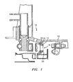
Fig. 1 is a schematic representation of a portion of a bypass air metering valve incorporating a bushing; -
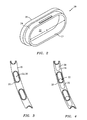
Fig. 2 is a perspective view of the bushing used in the valve ofFig. 1 ; -
Fig. 3 illustrates the metering ring in an open position; -
Fig. 4 illustrates the metering ring in a closed position; and -
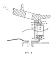
Fig. 5 illustrates the flow of a cooling fluid through a slot in the metering valve ofFig. 1 . - Referring now to the drawings, there is shown in
Fig. 1 a portion of abypass metering valve 10. Thevalve 10 includes acasing 12 having astationary case flange 14 in which a plurality ofslots 16 are located. While theslots 16 may have any desired shape, typically they are oval shaped. Thevalve 10 further includes ametering ring 18 which moves between an open position (seeFig. 3 ) and a closed position (seeFig. 4 ). Any suitable means known in the art may be used to move themetering ring 18 between its open and closed positions. - The
valve 10 further includes a plurality ofbushings 20 which are positioned within theslots 16, preferably by press fitting. Onebushing 20 is positioned within each of theslots 16. - As can be seen from
Fig. 2 , thebushing 20 has abody 21 which circumscribes aninternal opening 22. Theinternal opening 22, preferably has a shape which corresponds to the shape of theslot 16. In a most preferred embodiment of the present invention, thebody 21 and theinternal opening 22 are both oval shaped. - The
bushing 20 further has a raisedflange portion 24. The raisedflange portion 24 is positioned between thestationary case flange 14 and themovable ring 18. In operation, themetering ring 18 rides on asurface 26 of the raisedflange portion 24. - The
bushing 20 is preferably formed from a low friction material, such as a Resin/Carbon Fiber braid material or a high temperature thermoset plastic or superimide material. - Referring now to
Figs. 3 and 4 , in operation, themetering ring 18 is provided with a plurality ofslots 30 and moves between an open position and a closed position. In the open position (Fig. 3 ), themetering ring 18 has arespective slot 30 which aligns with theinternal opening 22 in thebushing 20 so that the fluid flowing through theinternal opening 22 is at its maximum. In the closed position (Fig. 4 ), the metering ring blocks a portion of theinternal opening 22 and theslot 30 overlaps the remaining portion of theinternal opening 22, thus reducing the amount of fluid which can flow through theinternal opening 22.Fig. 5 illustrates the flow of the fluid through theinternal opening 22. - In a preferred embodiment, the
metering ring slots 30 are spaced apart by a distance less than the widest dimension D of theinternal opening 22. In such an embodiment, theinternal opening 22 is never fully closed and is always partially open. Of course, if desired, themetering ring slots 30 may be spaced so as to allow for complete closure of theinternal openings 22. Cooling fluid could be bled through other holes elsewhere in the nozzle. - The
bushing 20 has arear lip portion 40 which helps position the bushing 20 in theslot 16. Therear lip portion 40 abuts the case flange 14 or abuts aspacer 42 positioned between thecase flange 14 and therear lip portion 40. Thespacer 42 could have scallops in it to avoid the bushing 20. - The
bushing 20 helps seal the slots orwindows 16 and allows upstream cooling fluid, such as air, to get between themetering ring 18 and thecase flange 14. The air between themetering ring 18 and the case flange 14 pressure balances themetering ring 18, thus reducing the friction on thesurface 26. This also reduces the load required to turn themetering ring 18. - The raised
flange portion 24 and therear lip portion 40 help facilitate the assembly of thebushings 20 into theslots 16. Therear lip portion 40 also provides a last chance containment for the bushing 20 if there is a pressure reversal. - The size of the
bushing 20 is determined by the open area flow required to cool or operate the nozzle and its attached flap hardware. - Still another advantage to the bushings is that they allow the
metering ring 18 to be mechanically and thermally independent from thestatic case flange 14, thus enhancing the operation of the metering ring.
Claims (10)
- A metering valve (10) comprising:a flange (14) having a plurality of slots (16) spaced circumferentially about an axial centreline;a metering ring (18) for controlling the amount of a fluid flowing through the slots (16)in an axial direction;a bushing (20) positioned within each of the flange slots (16); andsaid metering ring (18) riding on a surface (26) of said bushing (20);
wherein said metering ring (18) rotates, said bushing (20) has a raised flange portion (24) that is located between said rotating metering ring (18) and said flange (14), and said rotating metering ring (18) rides on a surface (26) of said raised flange portion (24);
characterised in that:said bushing (20) further has a rear lip portion (40) for securing said bushing (20) in position within said slot (16); wherein:said rear lip portion (40) abuts a surface of said flange (14); orsaid metering valve further comprises a spacer (42) positioned adjacent said flange (14), said rear lip portion abutting said spacer (42). - The metering valve according to claim 1, wherein each said slot (16) has a shape and each said bushing (20) has an internal opening (22) corresponding in shape to the shape of the slot (16).
- The metering valve according to claim 2, wherein each said slot (16) has an oval shape and each internal opening (22) is oval shaped.
- The metering valve according to any preceding claim, wherein each said bushing (20) is press fit into a respective one of said slots (16).
- The metering valve according to any preceding claim, wherein said bushing (20) is formed from a low friction material.
- The metering valve according to claim 5, wherein said low friction material comprises a material selected from the group consisting of a resin/carbon fiber braid material, a high temperature thermoset plastic material and a superimide material.
- The metering valve according to any preceding claim, further comprising:said metering ring (18) having a plurality of spaced apart slots (30);said bushing (20) having an internal opening (22); andsaid metering ring (18) being movable to a first position where one of said spaced apart slots (30) is aligned with said internal opening (22).
- The metering valve according to claim 7, further comprising said metering ring (18) being movable to a second position where a portion of said internal opening (30) is blocked by said metering ring (18).
- The metering valve according to claim 7 or 8, wherein each of said spaced apart slots (16) and said internal opening (22) is oval shaped and wherein said internal opening (22) has a widest dimension (D) and said slots (16) in said metering ring (18) are spaced apart by a distance less than said widest dimension (D) so that said internal opening (22) is always at least partially open.
- The metering valve according to any preceding claim, wherein said bushing (20) creates a gap between said flange (14) and said metering ring (18).
Applications Claiming Priority (1)
| Application Number | Priority Date | Filing Date | Title |
|---|---|---|---|
| US11/120,700 US7207352B2 (en) | 2005-05-02 | 2005-05-02 | Bushing for thermally independent bypass air metering valve |
Publications (3)
| Publication Number | Publication Date |
|---|---|
| EP1724444A2 EP1724444A2 (en) | 2006-11-22 |
| EP1724444A3 EP1724444A3 (en) | 2009-11-11 |
| EP1724444B1 true EP1724444B1 (en) | 2015-09-30 |
Family
ID=36698827
Family Applications (1)
| Application Number | Title | Priority Date | Filing Date |
|---|---|---|---|
| EP06251066.4A Active EP1724444B1 (en) | 2005-05-02 | 2006-02-28 | Bypass air metering valve |
Country Status (11)
| Country | Link |
|---|---|
| US (1) | US7207352B2 (en) |
| EP (1) | EP1724444B1 (en) |
| JP (1) | JP2006313011A (en) |
| KR (1) | KR20060114632A (en) |
| CN (1) | CN1858425A (en) |
| AU (1) | AU2006200659A1 (en) |
| CA (1) | CA2537678A1 (en) |
| IL (1) | IL173840A0 (en) |
| NO (1) | NO20061029L (en) |
| SG (1) | SG126823A1 (en) |
| TW (1) | TW200641246A (en) |
Families Citing this family (4)
| Publication number | Priority date | Publication date | Assignee | Title |
|---|---|---|---|---|
| US8267630B2 (en) * | 2009-07-13 | 2012-09-18 | United Technologies Corporation | Threaded flanged bushing for fastening applications |
| US9010123B2 (en) * | 2010-07-26 | 2015-04-21 | Honeywell International Inc. | Combustors with quench inserts |
| FR3061739B1 (en) * | 2017-01-06 | 2020-07-31 | Safran Aircraft Engines | TURBOMACHINE SET |
| US11635030B2 (en) | 2017-06-13 | 2023-04-25 | General Electric Company | Compressor bleed apparatus for a turbine engine |
Family Cites Families (19)
| Publication number | Priority date | Publication date | Assignee | Title |
|---|---|---|---|---|
| US1986252A (en) * | 1930-12-13 | 1935-01-01 | William F Conran | Regulator device |
| US2978221A (en) * | 1959-06-26 | 1961-04-04 | Edward Valves Inc | Resiliently seated valves and sealing structures therefor |
| US3135293A (en) * | 1962-08-28 | 1964-06-02 | Robert L Erwin | Rotary control valve |
| US3589829A (en) * | 1969-03-13 | 1971-06-29 | Anatoly Alexandrovich Schetini | Shutoff device for steam path of steam turbine |
| SU802562A1 (en) * | 1979-03-30 | 1981-02-07 | Харьковский Филиал Центральногоконструкторского Бюро Главэнерго-Pemohta Министерства Энергети-Ческой Промышленности Cccp | Adjustable nozzle unit of steam turbine |
| US4516606A (en) * | 1983-02-16 | 1985-05-14 | Exxon Research And Engineering Co. | Variable orifice valve assembly |
| US4953595A (en) * | 1987-07-29 | 1990-09-04 | Eastman Christensen Company | Mud pulse valve and method of valving in a mud flow for sharper rise and fall times, faster data pulse rates, and longer lifetime of the mud pulse valve |
| EP0520566B1 (en) * | 1991-06-24 | 1996-03-13 | NORSK HYDRO a.s. | Valve device having stationary and movable or turnable valve bodies |
| US5224818A (en) * | 1991-11-01 | 1993-07-06 | General Electric Company | Air transfer bushing |
| CA2082709A1 (en) * | 1991-12-02 | 1993-06-03 | Srinivasan Venkatasubbu | Variable stator vane assembly for an axial flow compressor of a gas turbine engine |
| FI107638B (en) * | 1996-03-11 | 2001-09-14 | Neles Jamesbury Oy | The control valve |
| US5979492A (en) * | 1999-01-05 | 1999-11-09 | Miller; David P. | Fluid level regulating sleeve valve |
| US6351949B1 (en) * | 1999-09-03 | 2002-03-05 | Allison Advanced Development Company | Interchangeable combustor chute |
| US6370752B1 (en) * | 2000-04-21 | 2002-04-16 | General Electric Company | Method for repositioning or repairing holes |
| US6688321B2 (en) * | 2000-11-06 | 2004-02-10 | David W. Palmer | Method and apparatus for a flow regulator having an integral hinge |
| US7516534B2 (en) * | 2001-11-25 | 2009-04-14 | Stresswave, Inc. | Method for attaching a nut element to a metal structure |
| US6805165B2 (en) * | 2002-05-02 | 2004-10-19 | Dai-You Lin | Adjustable air stream introducing device |
| FR2853930B1 (en) * | 2003-04-16 | 2007-02-23 | Snecma Moteurs | DEVICE FOR THE CONTROL OF VARIABLE-SETTING AUBES IN A TURBOMACHINE |
| FR2860045B1 (en) * | 2003-09-24 | 2006-01-06 | Snecma Moteurs | VENTILATION SYSTEM FOR A DIVERGENT CONVERGENT EJECTION TUBE |
-
2005
- 2005-05-02 US US11/120,700 patent/US7207352B2/en active Active
-
2006
- 2006-02-17 AU AU2006200659A patent/AU2006200659A1/en not_active Abandoned
- 2006-02-21 IL IL173840A patent/IL173840A0/en unknown
- 2006-02-23 CN CNA2006100711865A patent/CN1858425A/en active Pending
- 2006-02-24 SG SG200601224A patent/SG126823A1/en unknown
- 2006-02-27 CA CA 2537678 patent/CA2537678A1/en not_active Abandoned
- 2006-02-28 EP EP06251066.4A patent/EP1724444B1/en active Active
- 2006-02-28 KR KR1020060019027A patent/KR20060114632A/en active IP Right Grant
- 2006-03-02 NO NO20061029A patent/NO20061029L/en not_active Application Discontinuation
- 2006-03-02 TW TW095107032A patent/TW200641246A/en unknown
- 2006-03-02 JP JP2006055638A patent/JP2006313011A/en active Pending
Also Published As
| Publication number | Publication date |
|---|---|
| CN1858425A (en) | 2006-11-08 |
| EP1724444A3 (en) | 2009-11-11 |
| US7207352B2 (en) | 2007-04-24 |
| NO20061029L (en) | 2006-11-03 |
| EP1724444A2 (en) | 2006-11-22 |
| CA2537678A1 (en) | 2006-11-02 |
| KR20060114632A (en) | 2006-11-07 |
| IL173840A0 (en) | 2006-07-05 |
| TW200641246A (en) | 2006-12-01 |
| AU2006200659A1 (en) | 2006-11-16 |
| US20060243333A1 (en) | 2006-11-02 |
| SG126823A1 (en) | 2006-11-29 |
| JP2006313011A (en) | 2006-11-16 |
Similar Documents
| Publication | Publication Date | Title |
|---|---|---|
| CA2688727C (en) | Bypass air scoop for gas turbine engine | |
| US7946806B2 (en) | Gas turbine engine systems and related methods involving heat exchange | |
| EP3018323B1 (en) | Bleed valve | |
| US11073090B2 (en) | Valved airflow passage assembly for adjusting airflow distortion in gas turbine engine | |
| US5518365A (en) | Radial-flow exhaust gas turbocharger turbine with adjustable guide vanes | |
| EP2573364B1 (en) | Turbocharger with variable nozzle having labyrinth seal for vanes | |
| EP3225814A1 (en) | Secondary airflow passage for adjusting airflow distortion in gas turbine engine inlet | |
| US6681558B2 (en) | Method of increasing engine temperature limit margins | |
| EP2905425B1 (en) | Variable vane and seal arrangement | |
| EP1988260B1 (en) | Method and system for regulating a cooling fluid within a turbomachine in real time | |
| US5498128A (en) | Radial-flow exhaust gas turbocharger turbine with adjustable guide vanes | |
| EP3231997A1 (en) | Gas turbine engine airfoil bleed | |
| EP1724444B1 (en) | Bypass air metering valve | |
| CN111828176A (en) | Updating thermal management fluids in turbomachinery | |
| US6779967B2 (en) | Device for air mass flow control | |
| US7101146B2 (en) | Split vane flow blocker | |
| US8347601B2 (en) | Device for pivoting at least one pivotable element in a gas turbine engine | |
| US9239006B2 (en) | Gas turbine engine and system for modulating secondary air flow | |
| CN112539086A (en) | Sectional rotary supercharging device for cooling air of turbine rotor blade | |
| US20180266361A1 (en) | Aircraft gas turbine having a variable outlet nozzle of a bypass flow channel | |
| EP3567222B1 (en) | Variable diffuser having a respective penny for each vane | |
| CN105822362A (en) | Method for producing a variable turbine geometry |
Legal Events
| Date | Code | Title | Description |
|---|---|---|---|
| PUAI | Public reference made under article 153(3) epc to a published international application that has entered the european phase |
Free format text: ORIGINAL CODE: 0009012 |
|
| AK | Designated contracting states |
Kind code of ref document: A2 Designated state(s): AT BE BG CH CY CZ DE DK EE ES FI FR GB GR HU IE IS IT LI LT LU LV MC NL PL PT RO SE SI SK TR |
|
| AX | Request for extension of the european patent |
Extension state: AL BA HR MK YU |
|
| PUAL | Search report despatched |
Free format text: ORIGINAL CODE: 0009013 |
|
| AK | Designated contracting states |
Kind code of ref document: A3 Designated state(s): AT BE BG CH CY CZ DE DK EE ES FI FR GB GR HU IE IS IT LI LT LU LV MC NL PL PT RO SE SI SK TR |
|
| AX | Request for extension of the european patent |
Extension state: AL BA HR MK YU |
|
| 17P | Request for examination filed |
Effective date: 20100511 |
|
| AKX | Designation fees paid |
Designated state(s): DE GB |
|
| 17Q | First examination report despatched |
Effective date: 20100624 |
|
| GRAP | Despatch of communication of intention to grant a patent |
Free format text: ORIGINAL CODE: EPIDOSNIGR1 |
|
| INTG | Intention to grant announced |
Effective date: 20150519 |
|
| GRAS | Grant fee paid |
Free format text: ORIGINAL CODE: EPIDOSNIGR3 |
|
| GRAA | (expected) grant |
Free format text: ORIGINAL CODE: 0009210 |
|
| AK | Designated contracting states |
Kind code of ref document: B1 Designated state(s): DE GB |
|
| REG | Reference to a national code |
Ref country code: GB Ref legal event code: FG4D |
|
| REG | Reference to a national code |
Ref country code: DE Ref legal event code: R081 Ref document number: 602006046790 Country of ref document: DE Owner name: UNITED TECHNOLOGIES CORP. (N.D.GES.D. STAATES , US Free format text: FORMER OWNER: UNITED TECHNOLOGIES INC., HARTFORD, CONN., US |
|
| REG | Reference to a national code |
Ref country code: DE Ref legal event code: R096 Ref document number: 602006046790 Country of ref document: DE |
|
| REG | Reference to a national code |
Ref country code: DE Ref legal event code: R097 Ref document number: 602006046790 Country of ref document: DE |
|
| PLBE | No opposition filed within time limit |
Free format text: ORIGINAL CODE: 0009261 |
|
| STAA | Information on the status of an ep patent application or granted ep patent |
Free format text: STATUS: NO OPPOSITION FILED WITHIN TIME LIMIT |
|
| 26N | No opposition filed |
Effective date: 20160701 |
|
| REG | Reference to a national code |
Ref country code: DE Ref legal event code: R082 Ref document number: 602006046790 Country of ref document: DE Representative=s name: SCHMITT-NILSON SCHRAUD WAIBEL WOHLFROM PATENTA, DE |
|
| REG | Reference to a national code |
Ref country code: DE Ref legal event code: R082 Ref document number: 602006046790 Country of ref document: DE Representative=s name: SCHMITT-NILSON SCHRAUD WAIBEL WOHLFROM PATENTA, DE Ref country code: DE Ref legal event code: R081 Ref document number: 602006046790 Country of ref document: DE Owner name: UNITED TECHNOLOGIES CORP. (N.D.GES.D. STAATES , US Free format text: FORMER OWNER: UNITED TECHNOLOGIES CORPORATION, HARTFORD, CONN., US |
|
| PGFP | Annual fee paid to national office [announced via postgrant information from national office to epo] |
Ref country code: DE Payment date: 20200121 Year of fee payment: 15 |
|
| REG | Reference to a national code |
Ref country code: DE Ref legal event code: R119 Ref document number: 602006046790 Country of ref document: DE |
|
| PG25 | Lapsed in a contracting state [announced via postgrant information from national office to epo] |
Ref country code: DE Free format text: LAPSE BECAUSE OF NON-PAYMENT OF DUE FEES Effective date: 20210901 |
|
| PGFP | Annual fee paid to national office [announced via postgrant information from national office to epo] |
Ref country code: GB Payment date: 20230121 Year of fee payment: 18 |