EP1147849A1 - Method for repositioning or repairing holes - Google Patents
Method for repositioning or repairing holes Download PDFInfo
- Publication number
- EP1147849A1 EP1147849A1 EP01303611A EP01303611A EP1147849A1 EP 1147849 A1 EP1147849 A1 EP 1147849A1 EP 01303611 A EP01303611 A EP 01303611A EP 01303611 A EP01303611 A EP 01303611A EP 1147849 A1 EP1147849 A1 EP 1147849A1
- Authority
- EP
- European Patent Office
- Prior art keywords
- body portion
- hole
- enlarged hole
- diameter
- recess
- Prior art date
- Legal status (The legal status is an assumption and is not a legal conclusion. Google has not performed a legal analysis and makes no representation as to the accuracy of the status listed.)
- Withdrawn
Links
- 238000000034 method Methods 0.000 title claims abstract description 50
- 239000000758 substrate Substances 0.000 claims abstract description 55
- 229910052751 metal Inorganic materials 0.000 claims abstract description 41
- 239000002184 metal Substances 0.000 claims abstract description 41
- 238000003780 insertion Methods 0.000 claims description 7
- 230000037431 insertion Effects 0.000 claims description 7
- 230000015572 biosynthetic process Effects 0.000 claims description 6
- 238000004898 kneading Methods 0.000 claims description 4
- 238000010438 heat treatment Methods 0.000 description 5
- 238000005304 joining Methods 0.000 description 4
- 238000003466 welding Methods 0.000 description 4
- 238000009792 diffusion process Methods 0.000 description 3
- 238000005553 drilling Methods 0.000 description 3
- 239000000463 material Substances 0.000 description 3
- PXHVJJICTQNCMI-UHFFFAOYSA-N Nickel Chemical compound [Ni] PXHVJJICTQNCMI-UHFFFAOYSA-N 0.000 description 2
- 229910045601 alloy Inorganic materials 0.000 description 1
- 239000000956 alloy Substances 0.000 description 1
- 230000000712 assembly Effects 0.000 description 1
- 238000000429 assembly Methods 0.000 description 1
- 230000000903 blocking effect Effects 0.000 description 1
- 230000015556 catabolic process Effects 0.000 description 1
- 238000005336 cracking Methods 0.000 description 1
- 238000006731 degradation reaction Methods 0.000 description 1
- 238000003754 machining Methods 0.000 description 1
- 229910001092 metal group alloy Inorganic materials 0.000 description 1
- 230000005012 migration Effects 0.000 description 1
- 238000013508 migration Methods 0.000 description 1
- 238000003801 milling Methods 0.000 description 1
- 239000000203 mixture Substances 0.000 description 1
- 229910052759 nickel Inorganic materials 0.000 description 1
- 230000002093 peripheral effect Effects 0.000 description 1
- 229910000601 superalloy Inorganic materials 0.000 description 1
- UONOETXJSWQNOL-UHFFFAOYSA-N tungsten carbide Chemical compound [W+]#[C-] UONOETXJSWQNOL-UHFFFAOYSA-N 0.000 description 1
Images


Classifications
-
- B—PERFORMING OPERATIONS; TRANSPORTING
- B23—MACHINE TOOLS; METAL-WORKING NOT OTHERWISE PROVIDED FOR
- B23P—METAL-WORKING NOT OTHERWISE PROVIDED FOR; COMBINED OPERATIONS; UNIVERSAL MACHINE TOOLS
- B23P6/00—Restoring or reconditioning objects
- B23P6/002—Repairing turbine components, e.g. moving or stationary blades, rotors
- B23P6/005—Repairing turbine components, e.g. moving or stationary blades, rotors using only replacement pieces of a particular form
-
- F—MECHANICAL ENGINEERING; LIGHTING; HEATING; WEAPONS; BLASTING
- F01—MACHINES OR ENGINES IN GENERAL; ENGINE PLANTS IN GENERAL; STEAM ENGINES
- F01D—NON-POSITIVE DISPLACEMENT MACHINES OR ENGINES, e.g. STEAM TURBINES
- F01D5/00—Blades; Blade-carrying members; Heating, heat-insulating, cooling or antivibration means on the blades or the members
- F01D5/005—Repairing methods or devices
-
- F—MECHANICAL ENGINEERING; LIGHTING; HEATING; WEAPONS; BLASTING
- F01—MACHINES OR ENGINES IN GENERAL; ENGINE PLANTS IN GENERAL; STEAM ENGINES
- F01D—NON-POSITIVE DISPLACEMENT MACHINES OR ENGINES, e.g. STEAM TURBINES
- F01D5/00—Blades; Blade-carrying members; Heating, heat-insulating, cooling or antivibration means on the blades or the members
- F01D5/12—Blades
- F01D5/14—Form or construction
- F01D5/18—Hollow blades, i.e. blades with cooling or heating channels or cavities; Heating, heat-insulating or cooling means on blades
- F01D5/186—Film cooling
-
- B—PERFORMING OPERATIONS; TRANSPORTING
- B23—MACHINE TOOLS; METAL-WORKING NOT OTHERWISE PROVIDED FOR
- B23P—METAL-WORKING NOT OTHERWISE PROVIDED FOR; COMBINED OPERATIONS; UNIVERSAL MACHINE TOOLS
- B23P2700/00—Indexing scheme relating to the articles being treated, e.g. manufactured, repaired, assembled, connected or other operations covered in the subgroups
- B23P2700/06—Cooling passages of turbine components, e.g. unblocking or preventing blocking of cooling passages of turbine components
-
- Y—GENERAL TAGGING OF NEW TECHNOLOGICAL DEVELOPMENTS; GENERAL TAGGING OF CROSS-SECTIONAL TECHNOLOGIES SPANNING OVER SEVERAL SECTIONS OF THE IPC; TECHNICAL SUBJECTS COVERED BY FORMER USPC CROSS-REFERENCE ART COLLECTIONS [XRACs] AND DIGESTS
- Y02—TECHNOLOGIES OR APPLICATIONS FOR MITIGATION OR ADAPTATION AGAINST CLIMATE CHANGE
- Y02T—CLIMATE CHANGE MITIGATION TECHNOLOGIES RELATED TO TRANSPORTATION
- Y02T50/00—Aeronautics or air transport
- Y02T50/60—Efficient propulsion technologies, e.g. for aircraft
-
- Y—GENERAL TAGGING OF NEW TECHNOLOGICAL DEVELOPMENTS; GENERAL TAGGING OF CROSS-SECTIONAL TECHNOLOGIES SPANNING OVER SEVERAL SECTIONS OF THE IPC; TECHNICAL SUBJECTS COVERED BY FORMER USPC CROSS-REFERENCE ART COLLECTIONS [XRACs] AND DIGESTS
- Y10—TECHNICAL SUBJECTS COVERED BY FORMER USPC
- Y10T—TECHNICAL SUBJECTS COVERED BY FORMER US CLASSIFICATION
- Y10T29/00—Metal working
- Y10T29/49—Method of mechanical manufacture
- Y10T29/49316—Impeller making
- Y10T29/49318—Repairing or disassembling
-
- Y—GENERAL TAGGING OF NEW TECHNOLOGICAL DEVELOPMENTS; GENERAL TAGGING OF CROSS-SECTIONAL TECHNOLOGIES SPANNING OVER SEVERAL SECTIONS OF THE IPC; TECHNICAL SUBJECTS COVERED BY FORMER USPC CROSS-REFERENCE ART COLLECTIONS [XRACs] AND DIGESTS
- Y10—TECHNICAL SUBJECTS COVERED BY FORMER USPC
- Y10T—TECHNICAL SUBJECTS COVERED BY FORMER US CLASSIFICATION
- Y10T29/00—Metal working
- Y10T29/49—Method of mechanical manufacture
- Y10T29/49718—Repairing
- Y10T29/49732—Repairing by attaching repair preform, e.g., remaking, restoring, or patching
-
- Y—GENERAL TAGGING OF NEW TECHNOLOGICAL DEVELOPMENTS; GENERAL TAGGING OF CROSS-SECTIONAL TECHNOLOGIES SPANNING OVER SEVERAL SECTIONS OF THE IPC; TECHNICAL SUBJECTS COVERED BY FORMER USPC CROSS-REFERENCE ART COLLECTIONS [XRACs] AND DIGESTS
- Y10—TECHNICAL SUBJECTS COVERED BY FORMER USPC
- Y10T—TECHNICAL SUBJECTS COVERED BY FORMER US CLASSIFICATION
- Y10T29/00—Metal working
- Y10T29/49—Method of mechanical manufacture
- Y10T29/49718—Repairing
- Y10T29/49732—Repairing by attaching repair preform, e.g., remaking, restoring, or patching
- Y10T29/49734—Repairing by attaching repair preform, e.g., remaking, restoring, or patching and removing damaged material
-
- Y—GENERAL TAGGING OF NEW TECHNOLOGICAL DEVELOPMENTS; GENERAL TAGGING OF CROSS-SECTIONAL TECHNOLOGIES SPANNING OVER SEVERAL SECTIONS OF THE IPC; TECHNICAL SUBJECTS COVERED BY FORMER USPC CROSS-REFERENCE ART COLLECTIONS [XRACs] AND DIGESTS
- Y10—TECHNICAL SUBJECTS COVERED BY FORMER USPC
- Y10T—TECHNICAL SUBJECTS COVERED BY FORMER US CLASSIFICATION
- Y10T29/00—Metal working
- Y10T29/49—Method of mechanical manufacture
- Y10T29/49826—Assembling or joining
- Y10T29/49908—Joining by deforming
- Y10T29/49938—Radially expanding part in cavity, aperture, or hollow body
Definitions
- the present invention relates generally to method for repositioning or repairing holes in metal substrates such as metal components used in jet engines and the like, and more particularly to method for repositioning or repairing holes such metal substrates using a physically deformable metal insert.
- the blade is mounted to the disk, the center tang entering a peripheral annular space of the disk, with the two outer tangs extending along the outside surface of each side of the disk which also has holes that line up with the holes of the tangs.
- a retaining pin is then passed through the holes in the disk and the aligned holes of the tangs to attach each of the blades to the periphery of the disk.
- one or more of the holes can mislocated, misaligned, misdrilled, or damaged during assembly of the components or during use.
- the holes formed in these components can be subjected to stress during use and wear away or deform. This can lead to removal, discarding or scrapping of the component where the mislocated, misaligned, misdrilled, or damaged hole is located.
- This can be very expensive, especially in the case of certain components such as rotor or compressor disks used in jet engines.
- substantial expense has been incurred prior to joining the components to each other. Accordingly, as the value of the individual assembly increases, the margin of error in machining and joining these components together becomes even more critical.
- a variation of the method involved in U.S. Patent 4,953,777 is to use a threaded or flanged bushing to reposition or repair the hole.
- the threaded or flanged bushing is held within the enlarged hole by frictional forces.
- the use of threaded or flanged bushing may not be possible those situations where the hole to be repositioned or repaired is relatively small in diameter, where the area where the hole to be repositioned or repaired is relatively small or both.
- threaded or flanged bushings are frequently held in place by green tack welds that have a tendency to crack over time and allow the bushing to migrate axially within the hole.
- the present invention relates to a method for repositioning or repairing a hole in a metal substrate having a first and second surface where the hole extends through the metal substrate from the first surface to the second surface of the substrate.
- the diameter of the hole is enlarged through the metal substrate from the first to the second surface to form an enlarged hole.
- a first recess having a wall with at least a portion of its diameter larger than the diameter of the enlarged hole is formed in one surface of the metal substrate at one end of the enlarged hole.
- a second recess having a wall with at least a portion of its diameter larger than the diameter of the enlarged hole is formed in the other surface of the metal substrate at the other end of the enlarged hole.
- a physically deformable metal insert having a head portion and body portion is provided and is inserted through one recess at one end of the enlarged hole so that the body portion extends at least partially within the enlarged hole.
- the head portion of the insert has an end with a diameter larger than the diameter of the enlarged hole, and is sized and configured so as to be capable of frictionally engaging the wall of one of the recesses.
- the body portion of the insert has an end, a diameter sized to permit it to be inserted at least partially within the enlarged hole and a length such that the end of the body portion is capable of extending at least to the other recess.
- the head and body portions of the insert are then subjected to physical forces so as to cause the head portion of the insert to be deformed and frictionally engage the wall of the one recess, so as to cause the body portion of the insert to be deformed and frictionally engage the enlarged hole and so as to cause the end of the body portion to be deformed and frictionally engage the wall of the other recess so that insert becomes substantially axially fixed within the enlarged hole.
- a new, repositioned or repaired hole having a diameter smaller than that of the enlarged hole can then be formed in the fixed insert that extends axially therethrough from the end of the head portion to the end of the body portion.
- the method of the present allows mislocated, misaligned, misdrilled, or damaged holes in the metal substrate to be repaired or repositioned without the use of heat treatment that can cause distortion or degradation of metal substrate.
- the use of the deformable metal insert having the head portion with a diameter sized to frictionally engage the wall of one of the recesses formed in one surface of the metal substrate, along with the end of the body portion of the insert that is capable of being deformed to frictionally engage the wall of the other recess formed in the other surface of the substrate allows the insert to be substantially axially fixed within the enlarged hole. As a result, the insert tends not to migrate axially within the enlarged hole, even over time.
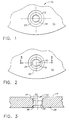
- FIG. 1 is a partial broken top plan view of a metal substrate with the hole to be repositioned or repaired having been enlarged by an exemplary embodiment of the method of the present invention.
- FIG. 2 is the partial broken top plan view of the metal substrate FIG.1 after forming locking portions in the enlarged hole.
- FIG. 3 is a side sectional view taken along line 3-3 of FIG. 2.
- FIG. 4 is a side view of the deformable insert
- FIG. 5 is the side sectional view of FIG. 3 after the deformable metal insert has been inserted into the enlarged hole.
- FIG. 6 is the side sectional view of FIG. 5 showing the physical forces being applied to the insert after insertion in the enlarged hole.
- FIG. 7 is the side sectional view of FIG. 6 showing the insert fixed within the enlarged hole, as well as the new repositioned hole formed in the fixed insert.
- FIG. 1 shows a portion of a metal substrate indicated by 10 from a metal component such as a nozzle support, or a rotor or compressor disk, fastener attachments, or the like that has a mislocated, misaligned, misdrilled, or damaged hole 12 requiring repair or repositioning and a first surface indicated by 14.
- hole 12 that is to be repaired or repositioned has already been enlarged to form an enlarged hole 18 in the metal substrate by drilling, boring or similar methods known to those skilled in the art.
- the method of the present invention can also be used to repair or reposition holes having other configurations, including those where the shape of the hole is oval, elliptical, rounded rectangular, TV screen shaped multiple lobes or the like.
- a recess 22 is formed in surface 14 at one end of hole 18. While recess 22 is typically formed after enlarged hole 18 is formed, the particular order of formation is not critical. As shown in FIG. 2, enlarged hole 18 is elongated across one axis, typically by milling hole 18, so that hole 18 to form a pair of opposed, typically ear-shaped locking portions 26 and 30. These locking portions 26 and 30 extend axially typically from one end of enlarged hole 18 to the other end of enlarged hole 18. As shown in FIG. 3, recess 22 comprises a countersink 32 that is connected at one end of enlarged hole 18 and counterbore 34 connected at one end of countersink 32 that extends to surface 14 of metal substrate 12.
- counterbore 34 is typically to receive the head of the fastener such as a bolt or pin that goes into hole 12 and to allow the head of the fastener to lies flush with or below surface 14. Accordingly, the formation of counterbore can be optional in the method of the present invention.
- the diameter of the wall of countersink 32 tapers inwardly in the direction away from surface 14 and counterbore 34 and towards the end of hole 18 to which it is connected so that the diameter of the wall of countersink 32 is larger at the end closer to surface 14 and smaller at the end connected to hole 18.
- substrate 10 has another (second) surface indicated by 38 that has formed therein a recess in the form of countersink 46 that is connected at the other end of hole 18.
- the diameter of the wall of countersink 46 tapers inwardly in the direction away from surface 38 and towards the other end of hole 18 to which it is connected so that the diameter of the wall of countersink 46 is larger at the end closer to surface 38 and smaller at the end of hole 18. While countersinks 32 and 46 are shown in FIG. 3 as being of similar configuration and diameter, they can also be of different configuration and diameter without departing from the method of the present invention.
- FIG. 4 shows an insert in the form of a rivet 52 made from a physically deformable metal, such as a nickel-based metal like Inco-600, which, as shown in FIG.5, is inserted through countersink 46 and within hole 18.
- rivet 52 has a head portion 56 and a body portion 60.
- Head portion 56 has an end indicated by 64 with a diameter larger than the diameter of at least a portion of, and typically most of, the diameter of the wall of countersink 46 so that rivet 52 cannot be inserted completely through hole 18.
- FIGs. 4 shows an insert in the form of a rivet 52 made from a physically deformable metal, such as a nickel-based metal like Inco-600, which, as shown in FIG.5, is inserted through countersink 46 and within hole 18.
- rivet 52 has a head portion 56 and a body portion 60.
- Head portion 56 has an end indicated by 64 with a diameter larger than the diameter of at least a portion of, and typically most of, the diameter of the wall of countersink 46 so that rivet 52 cannot
- head portion 56 has a tapered, frustoconical configuration that is typically sized to be of the same or similar configuration as countersink 46 so that it fits snug against the wall of countersink 46 when rivet 52 is inserted.
- body portion 60 has a cylindrical configuration that is typically sized to be of the same or similar diameter as hole 18 so that body portion 60 extends at least partially within, and preferably completely through, hole 18, when the rivet is inserted.
- body portion 60 has sufficient length so that its end indicated by 68 extends beyond the end of enlarge hole 18 and into countersink 32 of recess 22.
- Patent 3,653,243 (Ramseier), issued April 4, 1972 which discloses such radial-riveters.
- Other suitable methods for deforming rivet 52 include the use of the combination of a conventional impact riveter or rivet gun and blocking bar, as well as other forms mechanical squeezing.
- Tool head 76 preferably moves not only downwardly against end 68 of body portion 60 to apply the deforming forces, but also in series of overlapping orbital paths substantially parallel to the surface 14 of substrate 10 and substantially perpendicular to the longitudinal axis of body portion 60 so as to knead end 68 of body portion 60 outwardly, inwardly, in an overlapping fashion and generally towards the opposite surface 38 of the substrate.
- end 68 of body portion 60 deforms and frictionally engages the wall of countersink 36 closest the end of hole 18.
- radial forming In a preferred series of overlapping orbital paths referred to as "radial forming," the movement of tool head 76 forms a rosette pattern (typically an eleven-sided rosette pattern) that ensures uniform and consistent deformation of end 68 of body portion 60.
- protrusion 84 on support 82 resists the axial movement of body portion 60 of rivet 52 within enlarged hole 18 and thus applies deforming forces to end 64 of head portion 56.
- head portion 56 deforms and frictionally engages the wall of countersink 46.
- the combined deforming forces created by the movement of tool head 76 and the resistance of protrusion 84 on support 82 also cause body portion 60 within enlarged hole 18 to also deform into and frictionally engage locking portions 26 and 30 of hole 18.
- rivet 52 can have a tendency to rotate within enlarged hole 18 as tool head 76 moves in the series of overlapping orbital paths substantially parallel to surface 14 of substrate 10 (and substantially perpendicular to the longitudinal axis of body portion 60) so as to apply the deforming forces to end 68 of body portion 60.
- the body portion 60 of rivet 52 is less able to rotate within hole 18.
- rivet 52 becomes substantially axially fixed within hole 18. Indeed, the deformed and fixed rivet 52 tends not to migrate axially within hole 18 even over time as substrate 10 is subjected to stresses normally encountered during use.
- a new repositioned hole 88 of circular shape and cylindrical configuration is formed in fixed rivet 52.
- Hole 88 has diameter smaller than that of enlarged hole 18 and extends axially from end 64 of head portion 56 to end 68 of body portion 60.
- a support such as a backing plate, preferably positioned against the deformed head portion 56 while hole 88 is formed through end portion 68 of body portion 60.
- Use of the support or backing plate restricts and resists axial movement of the fixed rivet 52 so that it does not become dislodged from hole 18, or possibly stretch or become distorted.
- end 64 of head portion 56 is preferably at or below the surface 38 of substrate 10, while end 68 of body portion 60 can be at or below surface 14 of substrate 10. This can be achieved either by removing the excess portions of ends 64 or 68 after insert 52 has been fixed within hole 18, or more typically by applying sufficient force for a sufficient period of time through the combined movement of tool head 76 and the resistance of support 82, especially so that end 64 is deformed sufficiently so as to be at least flush with surface 38 of substrate 10.
Landscapes
- Engineering & Computer Science (AREA)
- Mechanical Engineering (AREA)
- General Engineering & Computer Science (AREA)
- Connection Of Plates (AREA)
- Powder Metallurgy (AREA)
Abstract
Description
- The present invention relates generally to method for repositioning or repairing holes in metal substrates such as metal components used in jet engines and the like, and more particularly to method for repositioning or repairing holes such metal substrates using a physically deformable metal insert.
- Many metal components such as nozzle supports and rotor or compressor disks used in jet engines require holes to be drilled in the component so that other components can bolted on or otherwise attached thereto. For example, U.S. Patent 4,953,777 (Griffith et al), issued September 4, 1990, shows fan rotor assemblies used in jet engines where the fan blades are mounted on a rotatable disk. The fan blades can have one or more tangs by which the blades are attached in spaced relation around the periphery of the disk. In one such embodiment, the blade has three tangs, each having a hole therein aligned along the same axis. The blade is mounted to the disk, the center tang entering a peripheral annular space of the disk, with the two outer tangs extending along the outside surface of each side of the disk which also has holes that line up with the holes of the tangs. A retaining pin is then passed through the holes in the disk and the aligned holes of the tangs to attach each of the blades to the periphery of the disk.
- Another example of an engine component with drilled holes is illustrated in U.S. Patent 5,111,570 (Baumgarten et al), issued May 12, 1992. In Figure 1 of this patent is shown an integrally bladed compressor disk 1 having a plurality of bolt holes 2 located on spaced arrangement around the circumference of
flange 3. Other engine components are joined to this compressor disk by bolting these components ontoflange 3 using bolt holes 2. - When holes are drilled or otherwise formed in such metal components, one or more of the holes can mislocated, misaligned, misdrilled, or damaged during assembly of the components or during use. For example, the holes formed in these components can be subjected to stress during use and wear away or deform. This can lead to removal, discarding or scrapping of the component where the mislocated, misaligned, misdrilled, or damaged hole is located. This can be very expensive, especially in the case of certain components such as rotor or compressor disks used in jet engines. For example, in the case of integrally bladed rotors, substantial expense has been incurred prior to joining the components to each other. Accordingly, as the value of the individual assembly increases, the margin of error in machining and joining these components together becomes even more critical.
- In the past, such mislocated, misaligned, misdrilled, or damaged holes were sometimes repaired by welding. However, welding and subsequent heat treatment to reposition or repair the hole can cause undesired distortion of the component, as well as a reduction the metal fatigue capability of a component that can be subjected to high temperatures and stresses during use, as is typically the case of the jet engine components. In the case of certain metal alloys such as high volume fraction gamma prime nickel-base superalloys, components made from such alloys are not weldable due to strain age cracking.
- Another method for repositioning or repairing such holes is described in U.S. Patent 4,953, 777. In the method of this patent, as particularly shown in Figures 2A-C and 3, hole 19 to be repaired is machined to a diameter sufficient to remove the damaged portion and to provide a new enlarged hole with a smooth finish. A metal bushing 20 having a composition compatible with the metal component being repaired is then inserted into this enlarged hole 19. The outer diameter of bushing 19 is machined to provide a close fit with the enlarged hole 19. Following insertion of bushing 20 into the enlarged hole 19, metal mandrel 21 is inserted into the bushing opening and the resulting assembly heated to cause diffusion bonding of bushing to the component 17. The assembly is then cooled and mandrel 21 is removed to provide the new hole formed by the opening in bushing 20. Again, like welding, diffusion bonding of the bushing according to this patent can cause undesired distortion of the component.
- A variation of the method involved in U.S. Patent 4,953,777 is to use a threaded or flanged bushing to reposition or repair the hole. In this situation, the threaded or flanged bushing is held within the enlarged hole by frictional forces. However, the use of threaded or flanged bushing may not be possible those situations where the hole to be repositioned or repaired is relatively small in diameter, where the area where the hole to be repositioned or repaired is relatively small or both. Also, threaded or flanged bushings are frequently held in place by green tack welds that have a tendency to crack over time and allow the bushing to migrate axially within the hole.
- Another method for repositioning or repairing such holes is described in U.S. Patent 5,111,570. In the method of this patent, as particularly shown in Figures 2-4, an enlarged hole indicated by 5 is formed such as by drilling in
flange 3. Repair plug, 6 is positioned in enlarged hole 5 and then a forge joining pressure is applied from both ends of the plug, such by upper andlower punches 9 and 10 that are shaped and positioned to promote uniform heating and deformation of plug 6. While this force is applied bypunches 9 and 10, the interface between plug 6 and the wall of enlarged hole 5 is locally heated. After the forge joining step, excess protrusion material 11 located on both sides offlange 3 can be machined away, leaving a smooth flange surface that can be redrilled to provide a new hole 13 of selected position and diameter as shown in Figure 7. Again, like welding and diffusion bonding, heating of the plug can cause undesired distortion of the component. In addition, like a threaded or flanged bushing, plug 6 can be subject to axial movement within enlarged hole 5 over time after the removal of the excess material 11. - Accordingly, it would desirable, therefore, to provide a method for repositioning or repairing mislocated, misaligned, misdrilled, or damaged holes in metal components that can be achieved without the use of an insert other than a threaded or flanged bushing, does not require heating of the component or insert used in the repositioning or repair of the hole, and which avoids or minimizes axial migration of the insert used to reposition or repair the hole.
- The present invention relates to a method for repositioning or repairing a hole in a metal substrate having a first and second surface where the hole extends through the metal substrate from the first surface to the second surface of the substrate. In this method, the diameter of the hole is enlarged through the metal substrate from the first to the second surface to form an enlarged hole. A first recess having a wall with at least a portion of its diameter larger than the diameter of the enlarged hole is formed in one surface of the metal substrate at one end of the enlarged hole. A second recess having a wall with at least a portion of its diameter larger than the diameter of the enlarged hole is formed in the other surface of the metal substrate at the other end of the enlarged hole. A physically deformable metal insert having a head portion and body portion is provided and is inserted through one recess at one end of the enlarged hole so that the body portion extends at least partially within the enlarged hole. The head portion of the insert has an end with a diameter larger than the diameter of the enlarged hole, and is sized and configured so as to be capable of frictionally engaging the wall of one of the recesses. The body portion of the insert has an end, a diameter sized to permit it to be inserted at least partially within the enlarged hole and a length such that the end of the body portion is capable of extending at least to the other recess. After insertion, the head and body portions of the insert are then subjected to physical forces so as to cause the head portion of the insert to be deformed and frictionally engage the wall of the one recess, so as to cause the body portion of the insert to be deformed and frictionally engage the enlarged hole and so as to cause the end of the body portion to be deformed and frictionally engage the wall of the other recess so that insert becomes substantially axially fixed within the enlarged hole. A new, repositioned or repaired hole having a diameter smaller than that of the enlarged hole can then be formed in the fixed insert that extends axially therethrough from the end of the head portion to the end of the body portion.
- The method of the present allows mislocated, misaligned, misdrilled, or damaged holes in the metal substrate to be repaired or repositioned without the use of heat treatment that can cause distortion or degradation of metal substrate. The use of the deformable metal insert having the head portion with a diameter sized to frictionally engage the wall of one of the recesses formed in one surface of the metal substrate, along with the end of the body portion of the insert that is capable of being deformed to frictionally engage the wall of the other recess formed in the other surface of the substrate, allows the insert to be substantially axially fixed within the enlarged hole. As a result, the insert tends not to migrate axially within the enlarged hole, even over time.
- An embodiment of the invention will now be described, by way of example, with reference to the accompanying drawings, in which:-
- FIG. 1 is a partial broken top plan view of a metal substrate with the hole to be repositioned or repaired having been enlarged by an exemplary embodiment of the method of the present invention.
- FIG. 2 is the partial broken top plan view of the metal substrate FIG.1 after forming locking portions in the enlarged hole.
- FIG. 3 is a side sectional view taken along line 3-3 of FIG. 2.
- FIG. 4 is a side view of the deformable insert
- FIG. 5 is the side sectional view of FIG. 3 after the deformable metal insert has been inserted into the enlarged hole.
- FIG. 6 is the side sectional view of FIG. 5 showing the physical forces being applied to the insert after insertion in the enlarged hole.
- FIG. 7 is the side sectional view of FIG. 6 showing the insert fixed within the enlarged hole, as well as the new repositioned hole formed in the fixed insert.
- Referring to the drawings, FIG. 1 shows a portion of a metal substrate indicated by 10 from a metal component such as a nozzle support, or a rotor or compressor disk, fastener attachments, or the like that has a mislocated, misaligned, misdrilled, or damaged
hole 12 requiring repair or repositioning and a first surface indicated by 14. As shown in FIG. 1,hole 12 that is to be repaired or repositioned has already been enlarged to form an enlargedhole 18 in the metal substrate by drilling, boring or similar methods known to those skilled in the art. While the hole that has been enlarged to form enlargedhole 18 has a circular shape so as to be cylindrical in configuration, the method of the present invention can also be used to repair or reposition holes having other configurations, including those where the shape of the hole is oval, elliptical, rounded rectangular, TV screen shaped multiple lobes or the like. - As also shown in FIG.1, a
recess 22 is formed insurface 14 at one end ofhole 18. Whilerecess 22 is typically formed after enlargedhole 18 is formed, the particular order of formation is not critical. As shown in FIG. 2, enlargedhole 18 is elongated across one axis, typically bymilling hole 18, so thathole 18 to form a pair of opposed, typically ear-shaped locking portions locking portions hole 18 to the other end of enlargedhole 18. As shown in FIG. 3,recess 22 comprises acountersink 32 that is connected at one end ofenlarged hole 18 andcounterbore 34 connected at one end ofcountersink 32 that extends to surface 14 ofmetal substrate 12. The purpose ofcounterbore 34 is typically to receive the head of the fastener such as a bolt or pin that goes intohole 12 and to allow the head of the fastener to lies flush with or belowsurface 14. Accordingly, the formation of counterbore can be optional in the method of the present invention. - As shown in FIG.3, the diameter of the wall of
countersink 32 tapers inwardly in the direction away fromsurface 14 andcounterbore 34 and towards the end ofhole 18 to which it is connected so that the diameter of the wall ofcountersink 32 is larger at the end closer to surface 14 and smaller at the end connected to hole 18. As also shown in FIG. 3,substrate 10 has another (second) surface indicated by 38 that has formed therein a recess in the form ofcountersink 46 that is connected at the other end ofhole 18. As also shown in FIG. 3 and likecountersink 32, the diameter of the wall ofcountersink 46 tapers inwardly in the direction away fromsurface 38 and towards the other end ofhole 18 to which it is connected so that the diameter of the wall ofcountersink 46 is larger at the end closer to surface 38 and smaller at the end ofhole 18. Whilecountersinks - FIG. 4 shows an insert in the form of a
rivet 52 made from a physically deformable metal, such as a nickel-based metal like Inco-600, which, as shown in FIG.5, is inserted throughcountersink 46 and withinhole 18. As shown in FIGs. 4 and 5, rivet 52 has ahead portion 56 and abody portion 60.Head portion 56 has an end indicated by 64 with a diameter larger than the diameter of at least a portion of, and typically most of, the diameter of the wall ofcountersink 46 so thatrivet 52 cannot be inserted completely throughhole 18. As also shown in FIGs. 4 and 5,head portion 56 has a tapered, frustoconical configuration that is typically sized to be of the same or similar configuration ascountersink 46 so that it fits snug against the wall ofcountersink 46 whenrivet 52 is inserted. As also shown in FIGs. 4 and 5,body portion 60 has a cylindrical configuration that is typically sized to be of the same or similar diameter ashole 18 so thatbody portion 60 extends at least partially within, and preferably completely through,hole 18, when the rivet is inserted. As shown in FIG. 5,body portion 60 has sufficient length so that its end indicated by 68 extends beyond the end of enlargehole 18 and intocountersink 32 ofrecess 22. - As shown in FIG. 6, physical forces are then applied to head and
body portions countersinks hole 18. These physical forces can be in the form a tool head or rivet set indicated by 76 that is part of, for example, a Bracker RN 281 radial-riveter that imparts radial forming forces throughtool head 76, and an anvil or support indicated by 82 with a golf tee shaped insert made of a hard material such as tungsten carbide fits within a recess insupport 82 and provides a cylindrical protrusion indicated by 84 that abutshead portion 56 ofrivet 52. See U.S. Patent 3,653,243 (Ramseier), issued April 4, 1972 which discloses such radial-riveters. Other suitable methods for deformingrivet 52 include the use of the combination of a conventional impact riveter or rivet gun and blocking bar, as well as other forms mechanical squeezing. -
Tool head 76 preferably moves not only downwardly againstend 68 ofbody portion 60 to apply the deforming forces, but also in series of overlapping orbital paths substantially parallel to thesurface 14 ofsubstrate 10 and substantially perpendicular to the longitudinal axis ofbody portion 60 so as to kneadend 68 ofbody portion 60 outwardly, inwardly, in an overlapping fashion and generally towards theopposite surface 38 of the substrate. As a result, end 68 ofbody portion 60 deforms and frictionally engages the wall of countersink 36 closest the end ofhole 18. In a preferred series of overlapping orbital paths referred to as "radial forming," the movement oftool head 76 forms a rosette pattern (typically an eleven-sided rosette pattern) that ensures uniform and consistent deformation ofend 68 ofbody portion 60. - As
tool head 76 applies deforming forces to end 68 ofbody portion 60 in the direction towardsopposite surface 38 ofsubstrate 10,protrusion 84 onsupport 82 resists the axial movement ofbody portion 60 ofrivet 52 withinenlarged hole 18 and thus applies deforming forces to end 64 ofhead portion 56. As a result,head portion 56 deforms and frictionally engages the wall ofcountersink 46. The combined deforming forces created by the movement oftool head 76 and the resistance ofprotrusion 84 onsupport 82 also causebody portion 60 withinenlarged hole 18 to also deform into and frictionally engage lockingportions hole 18. In the absence of lockingportions enlarged hole 18 astool head 76 moves in the series of overlapping orbital paths substantially parallel to surface 14 of substrate 10 (and substantially perpendicular to the longitudinal axis of body portion 60) so as to apply the deforming forces to end 68 ofbody portion 60. However, as thebody portion 60 withinenlarged hole 18 is deformed into and frictionally engages lockingportions body portion 60 ofrivet 52 is less able to rotate withinhole 18. Asbody portion 60 frictionally engages lockingportions enlarged hole 18, and especially because of the deformation and frictional engagement ofhead portion 56 with the wall ofcountersink 46, as well asend 68 ofbody portion 60 with the wall ofcountersink 32,rivet 52 becomes substantially axially fixed withinhole 18. Indeed, the deformed and fixedrivet 52 tends not to migrate axially withinhole 18 even over time assubstrate 10 is subjected to stresses normally encountered during use. - As shown in FIG. 7, a new repositioned
hole 88 of circular shape and cylindrical configuration is formed in fixedrivet 52.Hole 88 has diameter smaller than that ofenlarged hole 18 and extends axially fromend 64 ofhead portion 56 to end 68 ofbody portion 60. In forminghole 88 such as by drilling through fixedrivet 52, it can be desirable to use a support, such as a backing plate, preferably positioned against thedeformed head portion 56 whilehole 88 is formed throughend portion 68 ofbody portion 60. Use of the support or backing plate restricts and resists axial movement of the fixedrivet 52 so that it does not become dislodged fromhole 18, or possibly stretch or become distorted. It can also be desirable to initially drill a hole smaller in diameter than that of hole 88 (again preferably using a support or backing plate) to further minimize the tendency of fixedrivet 52 to be axially dislodged, stretched or distorted whenlarger diameter hole 88 is finally formed. - As also shown in FIGS. 6 and 7, end 64 of
head portion 56 is preferably at or below thesurface 38 ofsubstrate 10, whileend 68 ofbody portion 60 can be at or belowsurface 14 ofsubstrate 10. This can be achieved either by removing the excess portions ofends insert 52 has been fixed withinhole 18, or more typically by applying sufficient force for a sufficient period of time through the combined movement oftool head 76 and the resistance ofsupport 82, especially so thatend 64 is deformed sufficiently so as to be at least flush withsurface 38 ofsubstrate 10. - For completeness, various aspects of the invention are set out in the following numbered clauses:-
- 1. A method for repositioning or repairing a hole (12) in a metal substrate (10)
having a first (14) and second (38) surface wherein the hole (12) extends through the
substrate (10) from the first surface (14) to the second surface (38) of the substrate,
the method comprising the steps of
- (a) enlarging the diameter of the hole (12) to form an enlarged hole (18) through the substrate (10) from the first (14) to the second (38) surface;
- (b) forming in the first surface (14) a first recess (22) at one end of the enlarged hole (18), the first recess (22) having a wall (32) with at least a portion of its diameter larger than the diameter of the enlarged hole (18);
- (c) forming in the second surface (38) a second recess (46) at the other end of the enlarged hole (18), the second recess (46) having a wall with at least a portion of its diameter larger than the diameter of the enlarged hole (18);
- (d) providing a physically deformable metal insert (52) having a head portion (56) and body portion (60), the head portion (56) having an end (64) with a diameter larger than the diameter of the enlarged hole (18), and being sized and configured so as to be capable of frictionally engaging the wall of one of the recesses (46), the body portion (60) having an end (68), a diameter sized to permit the body portion (60) to be inserted at least partially within the enlarged hole (18) and a length such that the end (68) of the body portion (60) is capable of extending at least to the other recess (22);
- (e) inserting the insert (52) through the one recess (46) so that the body portion (60) extends at least partially within the enlarged hole (18);
- (f) after insertion, subjecting the head (56) and body (60) portions of the insert (52) to physical deforming forces so as to cause the head portion (56) to be deformed and frictionally engage the wall of the one recess (46), so as to cause the body portion (60) to be deformed and frictionally engage the enlarged hole (18) and so as to cause the end (68) of the body portion (60) to be deformed and frictionally engage the wall (32) of the other recess (22), so that the insert (52) becomes substantially axially fixed within the enlarged hole (18).
- 2. The method of clause 1 which comprises the further step (g) of forming another hole (88) having a diameter smaller than that of the enlarged hole (18) in the fixed insert (52) that extends axially therethrough from the end (64) of the head portion (56) to the end (68) of the body portion (60).
- 3. The method of clause 2 wherein the enlarged hole (18) has a cylindrical configuration.
- 4. The method of
clause 3 wherein the diameter of the wall (32) of the first recess (22) tapers inwardly in the direction away from the first surface (14) of the substrate (10) and towards one end of the enlarged hole (18) and wherein the diameter of the wall of the second recess (46) tapers inwardly in the direction away from the second surface (38) of the substrate (46) and towards the other end of the enlarged hole (18). - 5. The method of clause 4 wherein the enlarged hole (18) has formed therein a pair of opposed locking portions (26, 30) that extend axially from one end of the enlarged hole (18) to the other end thereof, and wherein the body portion (60) of the insert (52) within the enlarged holed (18) is deformed during step (f) into and frictionally engages the locking portions (26, 30) so that the body portion (60) is less able to rotate within the enlarged hole (18).
- 6. The method of clause 4 wherein the head portion (56) of the insert (52) has a tapered configuration sized to be similar in configuration to that of the recess (46) through which the insert (52) is inserted.
- 7. The method of clause 6 wherein the head portion (56) of the insert (52) has a frustoconical configuration and wherein the body portion (60) of the insert (52) has a cylindrical configuration
- 8. The method of clause 2 wherein the body portion (60) of the insert has sufficient length such that the end (68) of the body portion (60) extends beyond one end of the enlarged hole (18) and wherein step (f) is carried out by kneading the end (68) of the body portion (60) in the direction towards the opposite surface (38) of the substrate (10) while resisting axial movement of the body portion (60) within the enlarged hole (18).
- 9. The method of clause 8 wherein the end (68) of the body portion (60) of the insert (52) is kneaded during step (f) by a tool head (76) that moves in a series overlapping orbital paths substantially perpendicular to the longitudinal axis of the body portion (60).
- 10. The method of clause 9 wherein the movement during step (f) of the tool head (76) in the series of orbital paths forms a rosette pattern.
- 11. The method of clause 2 wherein the smaller diameter hole (88) is formed during step (g) through the end portion (68) of the body portion (60) of the fixed insert (52) and wherein axial movement of the fixed insert (52) is resisted during formation of the smaller diameter hole (88) by placing a support against deformed head portion (56) of the fixed insert (52).
- 12. A method for repositioning or repairing a hole (12) in a metal substrate (10)
having a first (14) and second (38) surface wherein the hole (12) extends through the
substrate (10) from the first surface (14) to the second surface (38) of the substrate,
the method comprising the steps of:
- (a) enlarging the diameter of the (12) to form an enlarged hole (18) having a cylindrical configuration through the substrate (10 from the first (14) to the second (38) surface;
- (b) forming in the first surface (14) a first recess (22) at one end of the enlarged hole, the first recess (22) having a wall (32) with a diameter that tapers inwardly in the direction away from the first surface (14) of the substrate (10) and towards one end of the enlarged hole (18);
- (c) forming in the second surface (38) a second recess (46) at the other end of the enlarged hole (18) , the second recess (46) having a wall with a diameter that tapers inwardly in the direction away from the second surface (38) of the substrate (10) and towards the other end of the enlarged hole (18);
- (d) providing a physically deformable metal rivet (52) having a head portion (56) with a frustoconical configuration and a body portion (60) with a cylindrical configuration, the head portion (56) being a capable of frictionally engaging the tapered wall (32) of one of the recesses (22) and having an end (64) with a diameter larger than the diameter of the enlarged hole (18), the body portion (60) having an end (68), a diameter sized to permit the body portion (60) to be inserted at least partially within the enlarged hole (18) and a length such that the end (68) of the body portion (60) is capable of extending at least to the other recess (22);
- (e) inserting the rivet (52) through the one recess (46) so that the body portion (60) extends at least partially within the enlarged hole (18);
- (f) after insertion, subjecting the head (56) and body (60) portions of the rivet (52) to physical deforming forces so as to cause the head portion (56) to be deformed and frictionally engage the tapered wall of the one recess (46), so as to cause the body portion (60)to be deformed and frictionally engage the enlarged hole (18) and so as to cause the end (68) of the body portion (60) to be deformed and frictionally engage the tapered wall (32) of the other recess (22), so that the rivet (52) becomes substantially axially fixed within the enlarged hole (18);
- (g) forming another hole (88) having a cylindrical configuration and a diameter smaller than that of the enlarged hole (18) in the fixed rivet (52) that extends axially therethrough from the end (64) of the head portion (56) to the end (68) of the body portion (60).
- 13. The method of
clause 12 wherein the enlarged hole (18) has formed therein a pair of opposed locking portions (26, 30) that extend axially from one end of the enlarged hole (18) to the other end thereof, and wherein the body portion (60) of the rivet (52) within the enlarged holed (18) is deformed during step (f) into and frictionally engages the locking portions (26, 30) so that the body portion (60) is less able to rotate within the enlarged hole. - 14. The method of clause 13 wherein the body portion (60) of the rivet (52) has sufficient length such that the end (68) of the body portion (60) extends beyond one end of the enlarged hole (18) and wherein step (f) is carried out by kneading the end (68) of the body portion (60) in the direction towards the opposite surface (38) of the substrate (10) while resisting axial movement of the body portion (60) within the enlarged hole (18).
- 15. The method of
clause 14 wherein the end (68) of the body portion (60) of the rivet (52) is kneaded during step (f) by a tool head (76) that moves in a series overlapping orbital paths substantially perpendicular to the longitudinal axis of the body portion (60). - 16. The method of
clause 14 wherein the movement during step (f) of the tool head (76) in the series of orbital paths forms a rosette pattern. - 17. The method of
clause 12 wherein the smaller diameter hole (88) is formed during step (g) through the end portion (68) of the body portion (60) of the fixed rivet (52) and wherein axial movement of the fixed rivet (52) is resisted during formation of the smaller diameter hole (88) by placing a support against deformed head portion (56) of the fixed rivet (52). -
Claims (10)
- A method for repositioning or repairing a hole (12) in a metal substrate (10) having a first (14) and second (38) surface wherein the hole (12) extends through the substrate (10) from the first surface (14) to the second surface (38) of the substrate, the method comprising the steps of:(a) enlarging the diameter of the hole (12) to form an enlarged hole (18) through the substrate (10) from the first (14) to the second (38) surface;(b) forming in the first surface (14) a first recess (22) at one end of the enlarged hole (18), the first recess (22) having a wall (32) with at least a portion of its diameter larger than the diameter of the enlarged hole (18);(c) forming in the second surface (38) a second recess (46) at the other end of the enlarged hole (18), the second recess (46) having a wall with at least a portion of its diameter larger than the diameter of the enlarged hole (18);(d) providing a physically deformable metal insert (52) having a head portion (56) and body portion (60), the head portion (56) having an end (64) with a diameter larger than the diameter of the enlarged hole (18), and being sized and configured so as to be capable of frictionally engaging the wall of one of the recesses (46), the body portion (60) having an end (68), a diameter sized to permit the body portion (60) to be inserted at least partially within the enlarged hole (18) and a length such that the end (68) of the body portion (60) is capable of extending at least to the other recess (22);(e) inserting the insert (52) through the one recess (46) so that the body portion (60) extends at least partially within the enlarged hole (18);(f) after insertion, subjecting the head (56) and body (60) portions of the insert (52) to physical deforming forces so as to cause the head portion (56) to be deformed and frictionally engage the wall of the one recess (46), so as to cause the body portion (60) to be deformed and frictionally engage the enlarged hole (18) and so as to cause the end (68) of the body portion (60)to be deformed and frictionally engage the wall (32) of the other recess (22), so that the insert (52) becomes substantially axially fixed within the enlarged hole (18).
- The method of claim 1 which comprises the further step (g) of forming another hole (88) having a diameter smaller than that of the enlarged hole (18) in the fixed insert (52) that extends axially therethrough from the end (64) of the head portion (56) to the end (68) of the body portion (60).
- The method of claim 2 wherein the diameter of the wall (32) of the first recess (22) tapers inwardly in the direction away from the first surface (14) of the substrate (10) and towards one end of the enlarged hole (18) and wherein the diameter of the wall of the second recess (46) tapers inwardly in the direction away from the second surface (38) of the substrate (46) and towards the other end of the enlarged hole (18).
- The method of claim 2 wherein the body portion (60) of the insert has sufficient length such that the end (68) of the body portion (60) extends beyond one end of the enlarged hole (18) and wherein step (f) is carried out by kneading the end (68) of the body portion (60) in the direction towards the opposite surface (38) of the substrate (10) while resisting axial movement of the body portion (60) within the enlarged hole (18).
- The method of claim 4 wherein the end (68) of the body portion (60) of the insert (52) is kneaded during step (f) by a tool head (76) that moves in a series overlapping orbital paths substantially perpendicular to the longitudinal axis of the body portion (60).
- The method of claim 2 wherein the smaller diameter hole (88) is formed during step (g) through the end portion (68) of the body portion (60) of the fixed insert (52) and wherein axial movement of the fixed insert (52) is resisted during formation of the smaller diameter hole (88) by placing a support against deformed head portion (56) of the fixed insert (52).
- A method for repositioning or repairing a hole (12) in a metal substrate (10) having a first (14) and second (38) surface wherein the hole (12) extends through the substrate (10) from the first surface (14) to the second surface (38) of the substrate, the method comprising the steps of:(a) enlarging the diameter of the (12) to form an enlarged hole (18) having a cylindrical configuration through the substrate (10 from the first (14) to the second (38) surface;(b) forming in the first surface (14) a first recess (22) at one end of the enlarged hole, the first recess (22) having a wall (32) with a diameter that tapers inwardly in the direction away from the first surface (14) of the substrate (10) and towards one end of the enlarged hole (18);(c) forming in the second surface (38) a second recess (46) at the other end of the enlarged hole (18) , the second recess (46) having a wall with a diameter that tapers inwardly in the direction away from the second surface (38) of the substrate (10) and towards the other end of the enlarged hole (18);(d) providing a physically deformable metal rivet (52) having a head portion (56) with a frustoconical configuration and a body portion (60) with a cylindrical configuration, the head portion (56) being a capable of frictionally engaging the tapered wall (32) of one of the recesses (22) and having an end (64) with a diameter larger than the diameter of the enlarged hole (18), the body portion (60) having an end (68), a diameter sized to permit the body portion (60) to be inserted at least partially within the enlarged hole (18) and a length such that the end (68) of the body portion (60) is capable of extending at least to the other recess (22);(e) inserting the rivet (52) through the one recess (46) so that the body portion (60) extends at least partially within the enlarged hole (18);(f) after insertion, subjecting the head (56) and body (60) portions of the rivet (52) to physical deforming forces so as to cause the head portion (56) to be deformed and frictionally engage the tapered wall of the one recess (46), so as to cause the body portion (60)to be deformed and frictionally engage the enlarged hole (18) and so as to cause the end (68) of the body portion (60) to be deformed and frictionally engage the tapered wall (32) of the other recess (22), so that the rivet (52) becomes substantially axially fixed within the enlarged hole (18);(g) forming another hole (88) having a cylindrical configuration and a diameter smaller than that of the enlarged hole (18) in the fixed rivet (52) that extends axially therethrough from the end (64) of the head portion (56) to the end (68) of the body portion (60).
- The method of Claim 7 wherein the enlarged hole (18) has formed therein a pair of opposed locking portions (26, 30) that extend axially from one end of the enlarged hole (18) to the other end thereof, and wherein the body portion (60) of the rivet (52) within the enlarged holed (18) is deformed during step (f) into and frictionally engages the locking portions (26, 30) so that the body portion (60) is less able to rotate within the enlarged hole.
- The method of claim 8 wherein the body portion (60) of the rivet (52) has sufficient length such that the end (68) of the body portion (60) extends beyond one end of the enlarged hole (18) and wherein step (f) is carried out by kneading the end (68) of the body portion (60) in the direction towards the opposite surface (38) of the substrate (10) while resisting axial movement of the body portion (60) within the enlarged hole (18).
- The method of claim 7 wherein the smaller diameter hole (88) is formed during step (g) through the end portion (68) of the body portion (60) of the fixed rivet (52) and wherein axial movement of the fixed rivet (52) is resisted during formation of the smaller diameter hole (88) by placing a support against deformed head portion (56) of the fixed rivet (52).
Applications Claiming Priority (2)
| Application Number | Priority Date | Filing Date | Title |
|---|---|---|---|
| US09/556,182 US6370752B1 (en) | 2000-04-21 | 2000-04-21 | Method for repositioning or repairing holes |
| US556182 | 2000-04-21 |
Publications (1)
| Publication Number | Publication Date |
|---|---|
| EP1147849A1 true EP1147849A1 (en) | 2001-10-24 |
Family
ID=24220234
Family Applications (1)
| Application Number | Title | Priority Date | Filing Date |
|---|---|---|---|
| EP01303611A Withdrawn EP1147849A1 (en) | 2000-04-21 | 2001-04-20 | Method for repositioning or repairing holes |
Country Status (5)
| Country | Link |
|---|---|
| US (1) | US6370752B1 (en) |
| EP (1) | EP1147849A1 (en) |
| JP (1) | JP2002045933A (en) |
| BR (1) | BR0101519A (en) |
| SG (1) | SG90243A1 (en) |
Cited By (11)
| Publication number | Priority date | Publication date | Assignee | Title |
|---|---|---|---|---|
| WO2005103451A1 (en) * | 2004-04-22 | 2005-11-03 | Mtu Aero Engines Gmbh | Method for obturating a core outlet of a turbine bucket and turbine bucket |
| EP1590165A4 (en) * | 2002-11-25 | 2006-03-15 | Stresswave Inc | Nut plates, and method for installation |
| EP1775061A1 (en) * | 2005-10-13 | 2007-04-18 | United Technologies Corporation | Hole repair technique and apparatus |
| EP1918065A1 (en) * | 2006-10-23 | 2008-05-07 | United Technologies Corporation | Engine mount bearing sleeve repair |
| EP1724444A3 (en) * | 2005-05-02 | 2009-11-11 | United Technologies Corporation | Bypass air metering valve |
| FR2961552A1 (en) * | 2010-06-21 | 2011-12-23 | Snecma | IMPACT COOLED CAVITY TURBINE TURBINE BLADE |
| WO2015139945A1 (en) * | 2014-03-17 | 2015-09-24 | Siemens Aktiengesellschaft | Method for closing a hole and component |
| EP3789591A1 (en) * | 2019-09-09 | 2021-03-10 | Raytheon Technologies Corporation | Variable vane arrangement with vane receptacle insert |
| CN113146162A (en) * | 2021-04-28 | 2021-07-23 | 上海三一重机股份有限公司 | Maintenance method for crushing shaft hole of operation machinery platform |
| EP4253723A1 (en) * | 2022-03-31 | 2023-10-04 | General Electric Company | Cooling passage exit opening cross-sectional area reduction for turbine system component |
| US12203387B2 (en) | 2022-03-31 | 2025-01-21 | Ge Infrastructure Technology Llc | Thermal profile based redirection of turbine system component coolant by targeted alteration of cooling passage exit opening cross-sectional area |
Families Citing this family (36)
| Publication number | Priority date | Publication date | Assignee | Title |
|---|---|---|---|---|
| US6615470B2 (en) * | 1997-12-15 | 2003-09-09 | General Electric Company | System and method for repairing cast articles |
| EP1247602B1 (en) * | 2001-04-04 | 2008-02-20 | Siemens Aktiengesellschaft | Method for producing an airfoil |
| US7204019B2 (en) * | 2001-08-23 | 2007-04-17 | United Technologies Corporation | Method for repairing an apertured gas turbine component |
| US6883700B2 (en) * | 2002-09-26 | 2005-04-26 | Siemens Westinghouse Power Corporation | Turbine blade closure system |
| US7377036B2 (en) * | 2004-10-05 | 2008-05-27 | General Electric Company | Methods for tuning fuel injection assemblies for a gas turbine fuel nozzle |
| US7650678B2 (en) * | 2006-03-30 | 2010-01-26 | United Technologies Corporation | Fabric bushing installation to repair a hole |
| US7640793B2 (en) * | 2007-09-12 | 2010-01-05 | United Technologies Corporation | Systems and methods for determining airflow parameters of gas turbine engine components |
| US9404374B2 (en) | 2008-04-09 | 2016-08-02 | United Technologies Corporation | Trunnion hole repair utilizing interference fit inserts |
| US8127581B2 (en) * | 2008-04-15 | 2012-03-06 | United Technologies Corporation | Turbine blade twist angle correction tooling |
| US8122601B2 (en) * | 2008-04-15 | 2012-02-28 | United Technologies Corporation | Methods for correcting twist angle in a gas turbine engine blade |
| US8230569B2 (en) * | 2009-01-20 | 2012-07-31 | United Technologies Corporation | Repair of case flange with bolt holes |
| CN102049543B (en) * | 2009-11-10 | 2013-10-30 | 柳州福臻车体实业有限公司 | Method for re-drilling positioning hole after heat treatment deformation of die insert |
| SI2412528T1 (en) * | 2010-07-28 | 2015-06-30 | Felix Boettcher Gmbh & Co. Kg | Method for repairing a cylinder |
| CN103562560B (en) * | 2011-05-31 | 2017-05-03 | 株式会社Ihi | Jig utilized to repair member joined by pin, and method utilizing same |
| CN102319976B (en) * | 2011-06-03 | 2012-12-26 | 哈尔滨飞机工业集团有限责任公司 | Method for processing locating hole of product locating piece in forming mould |
| CN102794609A (en) * | 2012-08-24 | 2012-11-28 | 无锡透平叶片有限公司 | Method for re-drilling center holes of blades |
| US10099322B2 (en) * | 2012-10-29 | 2018-10-16 | South Dakota Board Of Regents | Methods for cold spray repair |
| US10441962B2 (en) | 2012-10-29 | 2019-10-15 | South Dakota Board Of Regents | Cold spray device and system |
| FR3002181B1 (en) * | 2013-02-21 | 2015-02-20 | Airbus Operations Sas | DEVICE AND METHOD FOR REPAIRING DEFORMABLE CORRUGATED RINGS WITH A DAMAGED AREA OF AN INTERMEDIATE LAYER OF A MULTILAYER STRUCTURE |
| WO2015026798A1 (en) * | 2013-08-20 | 2015-02-26 | United Technologies Corporation | Replacing an aperture with an annular bushing in a composite laminated composite component |
| CN103433685B (en) * | 2013-09-16 | 2015-09-30 | 南车戚墅堰机车有限公司 | The insetting sleeve repair method of diesel-engine body cam hole |
| US9593595B2 (en) | 2014-04-14 | 2017-03-14 | Solar Turbines Incorporated | Method of remanufacturing a machine component |
| EP3134932B1 (en) | 2014-04-25 | 2021-08-25 | South Dakota Board of Regents | High capacity electrodes |
| CN105312593A (en) * | 2014-07-30 | 2016-02-10 | 桂林福达重工锻造有限公司 | Ejection rod hole drilling method after surfacing of crankshaft forging die |
| US9670984B2 (en) | 2015-01-05 | 2017-06-06 | Caterpillar Inc. | Method for remanufacturing flywheel |
| US20160230599A1 (en) * | 2015-02-09 | 2016-08-11 | United Technologies Corporation | Flangeless conical sleeve and method of repair |
| DE102016213578A1 (en) * | 2016-07-25 | 2018-01-25 | Bayerische Motoren Werke Aktiengesellschaft | Method for permanently inserting joining auxiliary elements into a component, component with joining auxiliary elements and component assembly |
| US10468674B2 (en) | 2018-01-09 | 2019-11-05 | South Dakota Board Of Regents | Layered high capacity electrodes |
| US20190217429A1 (en) * | 2018-01-16 | 2019-07-18 | General Electric Company | Systems and methods for resizing holes |
| KR102086162B1 (en) * | 2018-04-20 | 2020-03-06 | 서한산업(주) | Manufacturing method of wheel support member and |
| US11213897B2 (en) * | 2019-05-28 | 2022-01-04 | The Boeing Company | Method of assembling members of an assembly |
| US11185912B2 (en) | 2019-10-29 | 2021-11-30 | The Boeing Company | Automated rivet apparatus for automated installation of semi-tubular fastener rivets |
| CN111633429A (en) * | 2020-06-03 | 2020-09-08 | 一汽解放大连柴油机有限公司 | A tappet hole repairing device and a tappet hole repairing method |
| US11633798B1 (en) * | 2021-12-02 | 2023-04-25 | General Electric Company | Braze method to modify a passage |
| CN114310188B (en) * | 2022-01-07 | 2024-02-13 | 哈尔滨电机厂有限责任公司 | Method for fixing combined surface of large hydroelectric generating set split piece |
| FR3153008B1 (en) * | 2023-09-20 | 2026-01-30 | Safran Aircraft Engines | Offset crimp insert and its crimping process |
Citations (7)
| Publication number | Priority date | Publication date | Assignee | Title |
|---|---|---|---|---|
| US2010569A (en) * | 1934-03-28 | 1935-08-06 | Florence Pipe Foundry & Machin | Method of plugging holes in plates |
| GB694368A (en) * | 1950-07-11 | 1953-07-22 | Metropolitan Cammell Carriage | Improvements in and relating to rivets and riveted joints |
| US3653243A (en) * | 1969-04-11 | 1972-04-04 | Braecker Ag | Device for forming closing heads at rivets |
| US4953777A (en) * | 1986-10-08 | 1990-09-04 | Chromalloy Gas Turbine Corporation | Method for repairing by solid state diffusion metal parts having damaged holes |
| US5111570A (en) * | 1990-08-10 | 1992-05-12 | United Technologies Corporation | Forge joining repair technique |
| DE19622584C1 (en) * | 1996-06-05 | 1997-09-04 | Mtu Muenchen Gmbh | Filling body for repair of fault points in structural part surfaces |
| US5671521A (en) * | 1996-02-06 | 1997-09-30 | Briles; Franklin S. | Rivet clamp-up deformation |
Family Cites Families (15)
| Publication number | Priority date | Publication date | Assignee | Title |
|---|---|---|---|---|
| US222321A (en) * | 1879-12-02 | Improvement in drilling-machines | ||
| US3487530A (en) | 1967-10-09 | 1970-01-06 | Abex Corp | Method of repairing casting defects |
| US3519503A (en) | 1967-12-22 | 1970-07-07 | United Aircraft Corp | Fabrication method for the high temperature alloys |
| US3522648A (en) | 1968-11-29 | 1970-08-04 | Caterpillar Tractor Co | Sealed hole and method of producing |
| US3626568A (en) | 1969-04-23 | 1971-12-14 | Avco Corp | Method for bonding pins into holes in a hollow turbine blade |
| US3878599A (en) * | 1969-07-11 | 1975-04-22 | Multifastener Corp | Method of forming a nut and panel assembly |
| US4164807A (en) | 1974-03-19 | 1979-08-21 | King John O Jun | Method of forming a coldworked joint |
| US4221041A (en) * | 1978-10-02 | 1980-09-09 | Boeing Commercial Airplane Company | Semi-tubular rivets and method of using |
| SU1532177A1 (en) * | 1988-03-14 | 1989-12-30 | Харьковский авиационный институт им.Н.Е.Жуковского | Method of repairing rivetted joint with countersunk head |
| US4985979A (en) * | 1989-01-23 | 1991-01-22 | Mcdonnell Douglas Corporation | Method of installing interference fit sleeved fasteners having radiused intersection for stress coining |
| US5077882A (en) * | 1989-01-24 | 1992-01-07 | Adams Dale R | Method for reboring a housing |
| US4984347A (en) * | 1989-05-05 | 1991-01-15 | Mcdonnell Douglas Corporation | Method for attaching a doubler to a skin structure |
| US5651172A (en) * | 1990-01-26 | 1997-07-29 | Ste. Ateliers De La Haute-Garonne-Ets Auriol Et Cie | Process for the assembly of materials and riveting member for carrying out the process |
| GB9119022D0 (en) | 1991-09-05 | 1991-10-23 | Welding Inst | Friction forming |
| US5975406A (en) | 1998-02-27 | 1999-11-02 | The Boeing Company | Method to repair voids in aluminum alloys |
-
2000
- 2000-04-21 US US09/556,182 patent/US6370752B1/en not_active Expired - Fee Related
-
2001
- 2001-04-11 SG SG200102096A patent/SG90243A1/en unknown
- 2001-04-19 BR BR0101519-2A patent/BR0101519A/en not_active IP Right Cessation
- 2001-04-20 JP JP2001121840A patent/JP2002045933A/en not_active Withdrawn
- 2001-04-20 EP EP01303611A patent/EP1147849A1/en not_active Withdrawn
Patent Citations (7)
| Publication number | Priority date | Publication date | Assignee | Title |
|---|---|---|---|---|
| US2010569A (en) * | 1934-03-28 | 1935-08-06 | Florence Pipe Foundry & Machin | Method of plugging holes in plates |
| GB694368A (en) * | 1950-07-11 | 1953-07-22 | Metropolitan Cammell Carriage | Improvements in and relating to rivets and riveted joints |
| US3653243A (en) * | 1969-04-11 | 1972-04-04 | Braecker Ag | Device for forming closing heads at rivets |
| US4953777A (en) * | 1986-10-08 | 1990-09-04 | Chromalloy Gas Turbine Corporation | Method for repairing by solid state diffusion metal parts having damaged holes |
| US5111570A (en) * | 1990-08-10 | 1992-05-12 | United Technologies Corporation | Forge joining repair technique |
| US5671521A (en) * | 1996-02-06 | 1997-09-30 | Briles; Franklin S. | Rivet clamp-up deformation |
| DE19622584C1 (en) * | 1996-06-05 | 1997-09-04 | Mtu Muenchen Gmbh | Filling body for repair of fault points in structural part surfaces |
Cited By (18)
| Publication number | Priority date | Publication date | Assignee | Title |
|---|---|---|---|---|
| US7516534B2 (en) | 2001-11-25 | 2009-04-14 | Stresswave, Inc. | Method for attaching a nut element to a metal structure |
| EP1590165A4 (en) * | 2002-11-25 | 2006-03-15 | Stresswave Inc | Nut plates, and method for installation |
| WO2005103451A1 (en) * | 2004-04-22 | 2005-11-03 | Mtu Aero Engines Gmbh | Method for obturating a core outlet of a turbine bucket and turbine bucket |
| EP1724444A3 (en) * | 2005-05-02 | 2009-11-11 | United Technologies Corporation | Bypass air metering valve |
| EP1775061A1 (en) * | 2005-10-13 | 2007-04-18 | United Technologies Corporation | Hole repair technique and apparatus |
| US7552855B2 (en) | 2005-10-13 | 2009-06-30 | United Technologies Corporation | Hole repair technique and apparatus |
| US8028414B2 (en) | 2006-10-23 | 2011-10-04 | United Technologies Corporation | Engine mount bearing sleeve repair |
| US7810239B2 (en) | 2006-10-23 | 2010-10-12 | United Technologies Corporation | Engine mount bearing sleeve repair |
| EP1918065A1 (en) * | 2006-10-23 | 2008-05-07 | United Technologies Corporation | Engine mount bearing sleeve repair |
| FR2961552A1 (en) * | 2010-06-21 | 2011-12-23 | Snecma | IMPACT COOLED CAVITY TURBINE TURBINE BLADE |
| WO2011161357A1 (en) * | 2010-06-21 | 2011-12-29 | Snecma | Core for the manufacture of a turbine blade having impact-cooled leading edge cavity |
| WO2015139945A1 (en) * | 2014-03-17 | 2015-09-24 | Siemens Aktiengesellschaft | Method for closing a hole and component |
| EP3789591A1 (en) * | 2019-09-09 | 2021-03-10 | Raytheon Technologies Corporation | Variable vane arrangement with vane receptacle insert |
| CN113146162A (en) * | 2021-04-28 | 2021-07-23 | 上海三一重机股份有限公司 | Maintenance method for crushing shaft hole of operation machinery platform |
| EP4253723A1 (en) * | 2022-03-31 | 2023-10-04 | General Electric Company | Cooling passage exit opening cross-sectional area reduction for turbine system component |
| US11859512B2 (en) | 2022-03-31 | 2024-01-02 | General Electric Company | Cooling passage exit opening cross-sectional area reduction for turbine system component |
| US12203387B2 (en) | 2022-03-31 | 2025-01-21 | Ge Infrastructure Technology Llc | Thermal profile based redirection of turbine system component coolant by targeted alteration of cooling passage exit opening cross-sectional area |
| US12428964B2 (en) | 2022-03-31 | 2025-09-30 | Ge Infrastructure Technology Llc | Cooling passage exit opening cross-sectional area reduction for turbine system component |
Also Published As
| Publication number | Publication date |
|---|---|
| BR0101519A (en) | 2001-11-20 |
| JP2002045933A (en) | 2002-02-12 |
| SG90243A1 (en) | 2002-07-23 |
| US6370752B1 (en) | 2002-04-16 |
Similar Documents
| Publication | Publication Date | Title |
|---|---|---|
| US6370752B1 (en) | Method for repositioning or repairing holes | |
| JP3219154B2 (en) | Repairing method for forged products | |
| JP4198021B2 (en) | How to repair component cracks | |
| EP0705389B1 (en) | Self-drilling blind rivet and method for making a pressure-tight riveted joint by means of same | |
| EP0873476B1 (en) | Tacking fastener | |
| JP4686130B2 (en) | Swage-type fastener having optimized locking groove and crest and method for making the fastener | |
| EP1775061B1 (en) | Hole repair technique | |
| EP2106875B1 (en) | Hole repair technique | |
| WO1997025538A9 (en) | Tacking fastener | |
| US4809420A (en) | Method and apparatus for backing up mandrel exit holes in knuckle structures | |
| US7513024B2 (en) | Method for repairing structural cracks | |
| CN101218413A (en) | Rotary drill shaft, rotary drill thus equipped, and manufacturing method | |
| EP1623126B1 (en) | Blind fastener and method of removing it from a workpiece | |
| DE10361882B4 (en) | Rotor for the high-pressure turbine of an aircraft engine | |
| DE102009052882A1 (en) | Method and device for producing an integrally bladed rotor and rotor produced by the method | |
| US20230226618A1 (en) | Blind fastener | |
| US20070175015A1 (en) | Drilling apparatus and method | |
| EP1095208B1 (en) | Blade retention apparatus for gas turbine rotor | |
| USRE39582E1 (en) | Method for replacing a tacking fastener | |
| US7043811B2 (en) | Method of removing studs | |
| AU693138B2 (en) | Turbine blade repair | |
| EP2394026A2 (en) | Gas turbine blade for a turbomachine | |
| JP5436617B2 (en) | How to remove rivets |
Legal Events
| Date | Code | Title | Description |
|---|---|---|---|
| PUAI | Public reference made under article 153(3) epc to a published international application that has entered the european phase |
Free format text: ORIGINAL CODE: 0009012 |
|
| AK | Designated contracting states |
Kind code of ref document: A1 Designated state(s): AT BE CH CY DE DK ES FI FR GB GR IE IT LI LU MC NL PT SE TR Kind code of ref document: A1 Designated state(s): DE FR GB IT |
|
| AX | Request for extension of the european patent |
Free format text: AL;LT;LV;MK;RO;SI |
|
| 17P | Request for examination filed |
Effective date: 20020424 |
|
| AKX | Designation fees paid |
Free format text: DE FR GB IT |
|
| 17Q | First examination report despatched |
Effective date: 20021217 |
|
| GRAP | Despatch of communication of intention to grant a patent |
Free format text: ORIGINAL CODE: EPIDOSNIGR1 |
|
| STAA | Information on the status of an ep patent application or granted ep patent |
Free format text: STATUS: THE APPLICATION IS DEEMED TO BE WITHDRAWN |
|
| 18D | Application deemed to be withdrawn |
Effective date: 20040113 |