EP3106714A2 - Moteur à turbine à gaz à engrenage - Google Patents
Moteur à turbine à gaz à engrenage Download PDFInfo
- Publication number
- EP3106714A2 EP3106714A2 EP16169749.5A EP16169749A EP3106714A2 EP 3106714 A2 EP3106714 A2 EP 3106714A2 EP 16169749 A EP16169749 A EP 16169749A EP 3106714 A2 EP3106714 A2 EP 3106714A2
- Authority
- EP
- European Patent Office
- Prior art keywords
- planet
- gear
- planet gear
- annular
- gas turbine
- Prior art date
- Legal status (The legal status is an assumption and is not a legal conclusion. Google has not performed a legal analysis and makes no representation as to the accuracy of the status listed.)
- Granted
Links
Images


Classifications
-
- F—MECHANICAL ENGINEERING; LIGHTING; HEATING; WEAPONS; BLASTING
- F16—ENGINEERING ELEMENTS AND UNITS; GENERAL MEASURES FOR PRODUCING AND MAINTAINING EFFECTIVE FUNCTIONING OF MACHINES OR INSTALLATIONS; THERMAL INSULATION IN GENERAL
- F16H—GEARING
- F16H57/00—General details of gearing
- F16H57/04—Features relating to lubrication or cooling or heating
- F16H57/0467—Elements of gearings to be lubricated, cooled or heated
- F16H57/0479—Gears or bearings on planet carriers
-
- F—MECHANICAL ENGINEERING; LIGHTING; HEATING; WEAPONS; BLASTING
- F02—COMBUSTION ENGINES; HOT-GAS OR COMBUSTION-PRODUCT ENGINE PLANTS
- F02C—GAS-TURBINE PLANTS; AIR INTAKES FOR JET-PROPULSION PLANTS; CONTROLLING FUEL SUPPLY IN AIR-BREATHING JET-PROPULSION PLANTS
- F02C3/00—Gas-turbine plants characterised by the use of combustion products as the working fluid
- F02C3/04—Gas-turbine plants characterised by the use of combustion products as the working fluid having a turbine driving a compressor
-
- F—MECHANICAL ENGINEERING; LIGHTING; HEATING; WEAPONS; BLASTING
- F02—COMBUSTION ENGINES; HOT-GAS OR COMBUSTION-PRODUCT ENGINE PLANTS
- F02C—GAS-TURBINE PLANTS; AIR INTAKES FOR JET-PROPULSION PLANTS; CONTROLLING FUEL SUPPLY IN AIR-BREATHING JET-PROPULSION PLANTS
- F02C7/00—Features, components parts, details or accessories, not provided for in, or of interest apart form groups F02C1/00 - F02C6/00; Air intakes for jet-propulsion plants
- F02C7/36—Power transmission arrangements between the different shafts of the gas turbine plant, or between the gas-turbine plant and the power user
-
- F—MECHANICAL ENGINEERING; LIGHTING; HEATING; WEAPONS; BLASTING
- F16—ENGINEERING ELEMENTS AND UNITS; GENERAL MEASURES FOR PRODUCING AND MAINTAINING EFFECTIVE FUNCTIONING OF MACHINES OR INSTALLATIONS; THERMAL INSULATION IN GENERAL
- F16H—GEARING
- F16H1/00—Toothed gearings for conveying rotary motion
- F16H1/28—Toothed gearings for conveying rotary motion with gears having orbital motion
-
- F—MECHANICAL ENGINEERING; LIGHTING; HEATING; WEAPONS; BLASTING
- F16—ENGINEERING ELEMENTS AND UNITS; GENERAL MEASURES FOR PRODUCING AND MAINTAINING EFFECTIVE FUNCTIONING OF MACHINES OR INSTALLATIONS; THERMAL INSULATION IN GENERAL
- F16H—GEARING
- F16H57/00—General details of gearing
- F16H57/04—Features relating to lubrication or cooling or heating
- F16H57/042—Guidance of lubricant
- F16H57/0421—Guidance of lubricant on or within the casing, e.g. shields or baffles for collecting lubricant, tubes, pipes, grooves, channels or the like
- F16H57/0426—Means for guiding lubricant into an axial channel of a shaft
-
- F—MECHANICAL ENGINEERING; LIGHTING; HEATING; WEAPONS; BLASTING
- F16—ENGINEERING ELEMENTS AND UNITS; GENERAL MEASURES FOR PRODUCING AND MAINTAINING EFFECTIVE FUNCTIONING OF MACHINES OR INSTALLATIONS; THERMAL INSULATION IN GENERAL
- F16H—GEARING
- F16H57/00—General details of gearing
- F16H57/04—Features relating to lubrication or cooling or heating
- F16H57/042—Guidance of lubricant
- F16H57/0427—Guidance of lubricant on rotary parts, e.g. using baffles for collecting lubricant by centrifugal force
-
- F—MECHANICAL ENGINEERING; LIGHTING; HEATING; WEAPONS; BLASTING
- F16—ENGINEERING ELEMENTS AND UNITS; GENERAL MEASURES FOR PRODUCING AND MAINTAINING EFFECTIVE FUNCTIONING OF MACHINES OR INSTALLATIONS; THERMAL INSULATION IN GENERAL
- F16H—GEARING
- F16H57/00—General details of gearing
- F16H57/04—Features relating to lubrication or cooling or heating
- F16H57/042—Guidance of lubricant
- F16H57/043—Guidance of lubricant within rotary parts, e.g. axial channels or radial openings in shafts
-
- F—MECHANICAL ENGINEERING; LIGHTING; HEATING; WEAPONS; BLASTING
- F16—ENGINEERING ELEMENTS AND UNITS; GENERAL MEASURES FOR PRODUCING AND MAINTAINING EFFECTIVE FUNCTIONING OF MACHINES OR INSTALLATIONS; THERMAL INSULATION IN GENERAL
- F16H—GEARING
- F16H57/00—General details of gearing
- F16H57/04—Features relating to lubrication or cooling or heating
- F16H57/045—Lubricant storage reservoirs, e.g. reservoirs in addition to a gear sump for collecting lubricant in the upper part of a gear case
-
- F—MECHANICAL ENGINEERING; LIGHTING; HEATING; WEAPONS; BLASTING
- F16—ENGINEERING ELEMENTS AND UNITS; GENERAL MEASURES FOR PRODUCING AND MAINTAINING EFFECTIVE FUNCTIONING OF MACHINES OR INSTALLATIONS; THERMAL INSULATION IN GENERAL
- F16H—GEARING
- F16H57/00—General details of gearing
- F16H57/04—Features relating to lubrication or cooling or heating
- F16H57/0458—Oil-mist or spray lubrication; Means to reduce foam formation
- F16H57/046—Oil-mist or spray lubrication
-
- F—MECHANICAL ENGINEERING; LIGHTING; HEATING; WEAPONS; BLASTING
- F16—ENGINEERING ELEMENTS AND UNITS; GENERAL MEASURES FOR PRODUCING AND MAINTAINING EFFECTIVE FUNCTIONING OF MACHINES OR INSTALLATIONS; THERMAL INSULATION IN GENERAL
- F16H—GEARING
- F16H57/00—General details of gearing
- F16H57/04—Features relating to lubrication or cooling or heating
- F16H57/048—Type of gearings to be lubricated, cooled or heated
- F16H57/0482—Gearings with gears having orbital motion
- F16H57/0486—Gearings with gears having orbital motion with fixed gear ratio
-
- F—MECHANICAL ENGINEERING; LIGHTING; HEATING; WEAPONS; BLASTING
- F16—ENGINEERING ELEMENTS AND UNITS; GENERAL MEASURES FOR PRODUCING AND MAINTAINING EFFECTIVE FUNCTIONING OF MACHINES OR INSTALLATIONS; THERMAL INSULATION IN GENERAL
- F16H—GEARING
- F16H57/00—General details of gearing
- F16H57/08—General details of gearing of gearings with members having orbital motion
- F16H57/082—Planet carriers
-
- F—MECHANICAL ENGINEERING; LIGHTING; HEATING; WEAPONS; BLASTING
- F05—INDEXING SCHEMES RELATING TO ENGINES OR PUMPS IN VARIOUS SUBCLASSES OF CLASSES F01-F04
- F05D—INDEXING SCHEME FOR ASPECTS RELATING TO NON-POSITIVE-DISPLACEMENT MACHINES OR ENGINES, GAS-TURBINES OR JET-PROPULSION PLANTS
- F05D2260/00—Function
- F05D2260/40—Transmission of power
- F05D2260/403—Transmission of power through the shape of the drive components
- F05D2260/4031—Transmission of power through the shape of the drive components as in toothed gearing
- F05D2260/40311—Transmission of power through the shape of the drive components as in toothed gearing of the epicyclical, planetary or differential type
-
- F—MECHANICAL ENGINEERING; LIGHTING; HEATING; WEAPONS; BLASTING
- F05—INDEXING SCHEMES RELATING TO ENGINES OR PUMPS IN VARIOUS SUBCLASSES OF CLASSES F01-F04
- F05D—INDEXING SCHEME FOR ASPECTS RELATING TO NON-POSITIVE-DISPLACEMENT MACHINES OR ENGINES, GAS-TURBINES OR JET-PROPULSION PLANTS
- F05D2260/00—Function
- F05D2260/98—Lubrication
-
- F—MECHANICAL ENGINEERING; LIGHTING; HEATING; WEAPONS; BLASTING
- F16—ENGINEERING ELEMENTS AND UNITS; GENERAL MEASURES FOR PRODUCING AND MAINTAINING EFFECTIVE FUNCTIONING OF MACHINES OR INSTALLATIONS; THERMAL INSULATION IN GENERAL
- F16H—GEARING
- F16H57/00—General details of gearing
- F16H57/08—General details of gearing of gearings with members having orbital motion
- F16H2057/085—Bearings for orbital gears
Definitions
- the present disclosure concerns a geared gas turbine engine and in particular to a geared turbofan gas turbine engine or a geared turbo propeller gas turbine engine.
- Geared gas turbine engines have a gearbox to drive the fan or propeller.
- the gearbox may be a planetary gearbox which requires a lubricant supply to supply lubricant to the gears and the bearings of the planet gears.
- the lubricant lubricates and cools the gears and the bearings of the planet gears.
- the lubricant is usually supplied to a planet gear carrier and then supplied from the planet gear carrier to the bearings of the planet gears and to the gears.
- the planet gear carrier is generally provided with several internal passages which are produced in the planet gear carrier by casting and/or machining.
- the internal passages within the planet gear carrier generally have a small cross-sectional flow area which may lead to a significant loss of pressure in the lubricant.
- the internal passages within the planet gear carrier may lead to high stresses within the planet gear carrier or an increase in thickness of the planet gear carrier to accommodate the internal passages with a consequential increase in weight.
- the total volume of lubricant within the planet gear carrier is relatively small, which is rapidly depleted in the event of an interruption in the lubricant supply. Any pressure fluctuations in the lubricant supply may not be damped out before the lubricant is supplied to the gears or planet gear bearings.
- the manufacturing tolerances of the internal passages within the planet gear carrier may lead to undesirable differences in supply pressure at the different supply positions. It is expensive to produce the internal passages in the planet gear carrier by casting and/or machining.
- a gas turbine engine comprising a gearbox, the gearbox comprising a sun gear, an annulus gear, a plurality of planet gears and a planet gear carrier, each planet gear being rotatably mounted in the planet gear carrier by at least one planet gear bearing, the sun gear meshing with the planet gears and the planet gears meshing with the annulus gear, a lubrication system arranged to supply lubricant to the planet gear bearings and one or more of the sun gear, the annulus gear and the planet gears, the planet gear carrier comprising an annular extension, the lubrication system comprising an annular member arranged coaxially around and spaced from the annular extension to define an annular chamber, the annular member being sealed at its ends to the planet gear carrier, the annular chamber having a volume selected to form a reservoir of lubricant, the annular member having at least one inlet aperture to supply lubricant into the annular chamber, the planet carrier having at least one first passage to supply lubric
- the annular chamber may have a large volume to form a reservoir of lubricant.
- the annular extension may be rotatably mounted in a static structure.
- the planet gear carrier may comprise a first ring, a second ring spaced axially from the first ring and a plurality of circumferentially spaced axles extending axially between the first ring and the second ring, each planet gear being rotatably mounted on a respective one of the axles and the annular extension extending from the first ring.
- Each planet gear may be rotatably mounted on the planer gear carrier by a journal bearing or at least one roller bearing.
- Each planet gear may be rotatably mounted on the planer gear carrier by two roller bearings.
- the annular member may comprise a cylindrical portion arranged around the annular extension and a radially extending portion spaced axially from the planet carrier.
- An end of the cylindrical portion may be sealed to the annular extension and a radially outer end of the radially extending portion may be sealed to the planet gear carrier.
- the radially extending portion may be frustoconical.
- the annular member may be frustoconical and arranged around the annular extension.
- a radially inner end of the frustoconical annular member may be sealed to the annular extension and a radially outer end of the frustoconical annular member may be sealed to the planet gear carrier.
- the planet gear carrier may have a plurality of second passages to supply lubricant to the planet gear bearings.
- Each second passage may extend through the first ring of the planet gear carrier to the interior of the respective axle.
- Each axle may have at least one passage extending there-through to supply lubricant to the respective planet gear bearing.
- each second passage may extend through the first ring of the planet gear carrier to at least one internal passage within the respective axle.
- Each axle may have at least one passage extending there-through from the at least one internal passage to supply lubricant to the respective planet gear bearing.
- the planet gear carrier may have a plurality of first passages to supply lubricant to one or more of the sun gear, the annulus gear and the planet gears.
- Each first passage may extend axially through the first ring of the planet gear carrier to a respective spray tube.
- Each spray tube may have at least one aperture to supply lubricant onto the sun gear and a planet gear.
- Each spray tube may have a plurality of apertures to supply lubricant onto the sun gear and a planet gear.
- An annular dividing member may be positioned radially between the annular extension and the annular member, the annular dividing member being sealed to the planet carrier to define a second annular chamber, the second annular chamber being arranged to supply lubricant via the at least one first passage to one or more of the sun gear, the annulus gear and the planet gears and the annular chamber being arranged to supply lubricant via the at least one second passage to the planet gear bearings.
- the gas turbine engine may comprise a propulsor, an intermediate-pressure compressor, a high-pressure compressor, a high-pressure turbine and a low-pressure turbine, the high-pressure turbine is arranged to directly drive the high-pressure compressor, the low-pressure turbine is arranged to directly drive the intermediate-pressure compressor and the low-pressure turbine is arranged to drive the propulsor via a gearbox.
- the gas turbine engine may comprising a propulsor, an intermediate-pressure compressor, a high-pressure compressor, a high-pressure turbine and a low-pressure turbine, the high-pressure turbine is arranged to directly drive the high-pressure compressor, the low-pressure turbine is arranged to directly drive the propulsor and the low-pressure turbine is arranged to drive the intermediate-pressure compressor via a gearbox.
- the gas turbine engine may comprise a propulsor, an intermediate-pressure compressor, a high-pressure compressor, a high-pressure turbine, an intermediate-pressure turbine and a low-pressure turbine, the high-pressure turbine is arranged to directly drive the high-pressure compressor, the intermediate-pressure turbine is arranged to directly drive the intermediate-pressure compressor and the low-pressure turbine is arranged to drive the propulsor via a gearbox.
- the gas turbine engine may comprise a propulsor, a high-pressure compressor, a high-pressure turbine and a low-pressure turbine, the high-pressure turbine is arranged to directly drive the high-pressure compressor and the low-pressure turbine is arranged to drive the propulsor via a gearbox.
- the gas turbine engine comprises a first propulsor, a second propulsor, an intermediate-pressure compressor, a high-pressure compressor, a high-pressure turbine, an intermediate-pressure turbine and a low-pressure turbine
- the high-pressure turbine is arranged to directly drive the high-pressure compressor
- the intermediate-pressure turbine is arranged to drive the intermediate-pressure compressor
- the low-pressure turbine is arranged to drive the first propulsor and the second propulsor via a gearbox.
- the sun gear may be driven by the low-pressure turbine, the annulus gear may be secured to static structure and the planet gear carrier may be arranged to drive the propulsor.
- the sun gear may be driven by the low-pressure turbine, the planet gear carrier may be secured to static structure and the annulus gear may be arranged to drive the propulsor.
- the planet gear carrier may be driven by the low-pressure turbine, the sun gear may be secured to static structure and the annulus gear may be arranged to drive a propulsor.
- the sun gear may be driven by the low-pressure turbine, the planet gear carrier may be arranged to drive a first propulsor and the annulus gear may be arranged to drive a second propulsor.
- the propulsor is a fan or a propeller.
- a gearbox comprising a sun gear, an annulus gear, a plurality of planet gears and a planet gear carrier, each planet gear being rotatably mounted in the planet gear carrier by at least one planet gear bearing, the sun gear meshing with the planet gears and the planet gears meshing with the annulus gear, a lubrication system arranged to supply lubricant to the planet gear bearings and one or more of the sun gear, the annulus gear and the planet gears, the planet gear carrier comprising an annular extension, the lubrication system comprising an annular member arranged coaxially around and spaced from the annular extension to define an annular chamber, the annular member being sealed at its ends to the planet gear carrier, the annular member having at least one inlet aperture to supply lubricant into the annular chamber, the planet carrier having at least one first passage to supply lubricant to one or more of the sun gear, the annulus gear and the planet gears and at least one second passage to supply lubricant
- a method of operating a gas turbine engine comprising a gearbox, the gearbox comprising a sun gear, an annulus gear, a plurality of planet gears and a planet gear carrier, each planet gear being rotatably mounted in the planet gear carrier by at least one planet gear bearing, the sun gear meshing with the planet gears and the planet gears meshing with the annulus gear, a lubrication system arranged to supply lubricant to the planet gear bearings and one or more of the sun gear, the annulus gear and the planet gears, the planet gear carrier comprising an annular extension, the lubrication system comprising a lubricant supply, an annular member arranged coaxially around and spaced from the annular extension to define an annular chamber, the annular member being sealed at its ends to the planet gear carrier, the annular chamber having a volume selected to form a reservoir of lubricant, the annular member having at least one inlet aperture to supply lubricant into
- a geared turbofan gas turbine engine is generally indicated at 10, having a principal and rotational axis 9.
- the engine 10 comprises, in axial flow series, an air intake 12, a propulsive fan 13, an intermediate-pressure, or booster, compressor 14, a high-pressure compressor 15, combustion equipment 16, a high-pressure turbine 17, a low-pressure turbine 19 and a core exhaust nozzle 20.
- the intermediate-pressure compressor 14, the high-pressure compressor 15, the combustion equipment 16, the high-pressure turbine 17 and the low-pressure turbine 19 form a core engine 11.
- a nacelle 21 generally surrounds the engine 10 and defines the intake 12, a bypass duct 22 and a bypass exhaust nozzle 18.
- the gas turbine engine 10 works in the conventional manner so that air entering the intake 12 is accelerated by the fan 13 to produce two air flows: a first air flow A into the intermediate-pressure compressor 14 and a second air flow B which passes through the bypass duct 22 to provide the majority of the propulsive thrust.
- the intermediate-pressure compressor 14 compresses the air flow directed into it before delivering that air to the high-pressure compressor 15 where further compression takes place.
- the compressed air exhausted from the high-pressure compressor 15 is directed into the combustion equipment 16 where it is mixed with fuel and the mixture combusted.
- the resultant hot combustion products then expand through, and thereby drive the high and low-pressure turbines 17, 19 before being exhausted through the core nozzle 20 to provide additional propulsive thrust.
- the high-pressure turbine 17 drives the high-pressure compressor 15 by a shaft 23.
- the low-pressure turbine 19 drives the intermediate-pressure compressor 14 directly via shafts 26 and 27.
- the low-pressure turbine 19 drives the fan 13 indirectly via the shaft 26, a gearbox 28 and a shaft 38.
- the gearbox 28 comprises a sun gear 30, an annulus gear 32, a plurality of planet gears 34 and a planet gear carrier 36.
- the sun gear 30 meshes with the planet gears 34 and the planet gears 32 mesh with the annulus gear 32.
- the planet gear carrier 36 constrains the planet gears 34 to precess around the sun gear 30 in synchronicity whilst enabling each planet gear 34 to rotate about its own axis independently.
- the planet gear carrier 36 is coupled via the shaft 38 to the fan 13 in order to drive its rotation about the engine axis 9.
- the annulus gear 32 is coupled to a static structure 24.
- the axes of the planet gears 34 and the axis of the planet gear carrier 36 are parallel to the engine axis 9.
- the gearbox 28 is shown more clearly in figures 3 and 4 and the planet gear carrier 36 comprises a first ring 36A, a second ring 36B spaced axially from the first ring 36A and a plurality of circumferentially spaced axles 40 which extend axially between the first ring 36A and the second ring 36B.
- Each planet gear 34 is rotatably mounted on a respective one of the axles 40 and an annular extension, e.g. an extension shaft, 36C extends axially from the first ring 36A.
- Each planet gear 34 is rotatably mounted in the planet gear carrier 36 by at least one planet gear bearing 42.
- the extension shaft 36C is rotatably mounted in the static structure 24 by a bearing 44.
- each planet gear 34 is rotatably mounted on the planer gear carrier 36 by two roller bearings 42.
- each planet gear 34 may be rotatably mounted on the planer gear carrier 36 by a journal bearing.
- a lubrication system 46 is arranged to supply lubricant to the planet gear bearings 42, the sun gear 30 and the planet gears 34.
- the lubrication system 46 comprises an annular member 48 arranged coaxially around and spaced from the extension shaft 36C to define an annular chamber 50.
- the annular member 48 is sealed at its ends to the planet gear carrier 36.
- the annular member 48 has at least one inlet aperture 52 to supply lubricant into the annular chamber 50.
- the annular member 48 has a plurality of circumferentially spaced inlet apertures 52.
- the planet carrier 36 has at least one first passage 54 to supply lubricant to the sun gear 30 and the planet gears 34 and at least one second passage 56 to supply lubricant to the planet gear bearings 42.
- the annular chamber 50 has a large volume to form a reservoir of lubricant for the sun gear 30, the planet gears 34 and the planet gear bearings 42.
- the planet gear carrier 36 has a plurality of circumferentially spaced first passages 54 to supply lubricant to the sun gear 30 and the planet gears 34.
- Each first passage 54 extends axially through the first ring 36A of the planet gear carrier 36 to a respective spray tube 58.
- Each spray tube 58 has at least one aperture 60 to supply lubricant onto the sun gear 30 and a respective one of the planet gears 34.
- Each spray tube 58 in particular has a plurality of axially spaced apertures 60 to supply lubricant onto the sun gear 30 and the respective one of the planet gears 34.
- Each spray tube 58 is positioned close to the region where the sun gear 30 meshes with a respective one of the planet gears 34 and the apertures 60 in each spray tube 58 directs the lubricant onto the region where the sun gear 30 meshes with a respective one of the planet gears 34.
- the planet gear carrier 36 has a plurality of circumferentially spaced second passages 56 to supply lubricant to the planet gear bearings 42.
- Each second passage 56 extends axially and radially through the first ring 36A of the planet gear carrier 36 and though a respective one of the axles 40 to the interior of the respective axle 40.
- Each axle 40 also has at least one passage extending radially there-through to supply lubricant to the respective planet gear bearing 42, e.g. to both of the roller bearings 42 or to the journal bearing.
- each second passage may extend axially and radially through the first ring 36A of the planet gear carrier 36 to at least one internal passage within the respective axle 40.
- Each axle 40 may have at least one passage extending there-through from the at least one internal passage to supply lubricant to the respective planet gear bearing 42.
- the annular member 48 comprises a cylindrical portion 51 arranged coaxially around the extension shaft 36C of the planer gear carrier 36 and a radially extending portion 53 spaced axially from the first ring 36A of the planet gear carrier 36.
- a downstream end 47 of the cylindrical portion 51 of the annular member 48 is sealed to the extension shaft 36C of the planet gear carrier 36 by an annular seal 68 and an upstream end 49, a radially outer end, of the radially extending portion 53 of the annular member 48 is sealed to the planet gear carrier 36 by an annular seal 70.
- the radially extending portion 53 in this example is frustoconical. There may be a smoothly curved junction between the cylindrical portion 51 and the frustoconical portion 53 of the annular member 48.
- downstream end 47 of the cylindrical portion 51 of the annular member 48 may be sealed to the extension shaft 36C of the planet gear carrier 36 by welding, brazing or by providing an interference fit and the upstream end 49, the radially outer end, of the radially extending portion 53 of the annular member 48 may be sealed to the planet gear carrier 36 welding, brazing or by providing an interference fit.
- a pipe 62 is arranged to supply lubricant to a lubricant coupling 64 which has at least one outlet aperture 66 to supply lubricant to the annular chamber 50 via the inlet aperture, or apertures, 52 in the annular member 48.
- the lubricant coupling 64 has a plurality of circumferentially spaced outlet apertures 66 to supply lubricant to the annular chamber 50.
- the lubricant coupling 64 is mounted on the static structure 24 and lubricant coupling seals (not shown) are provided between the lubricant coupling 66 and the annular member 48.
- the lubricant coupling 64 is annular and is arranged coaxially around the annular member 48.
- the advantage of this arrangement of the present disclosure is that the annular chamber has a relatively large cross-sectional flow area, compared to the previous arrangement, and therefore the pressure losses in the lubricant are reduced and the lubricant may be delivered to the sun gear and planet gears and the planet gear bearings with a more uniform pressure.
- a further advantage is that the number of passages provided through, or within, the planet gear carrier is reduced and therefore stress concentrations are reduced and the risk of manufacturing non-conformance is reduced.
- the volume of the annular chamber is larger than the previous arrangement and therefore the volume of the annular chamber may be selected to maintain a reserve of lubricant in the event of a significant interruption in the supply of lubricant from the lubricant supply, lubricant tank.
- the reserve of lubricant in the annular chamber would be able to maintain some hydraulic pressure due to the centrifugal forces resulting from the rotation of the planet gear carrier and the annular member in the embodiments of the disclosure in which the planet gear carrier is rotatably mounted in the static structure.
- the reserve of lubricant in the annular chamber may help to damp out any pressure fluctuations in the lubricant supply system before distributing the lubricant to the planet gear bearings and the sun gear and the planet gears. It is relatively easy to manufacture the annular member so as to form the annular chamber compared to casting and/or machining the internal passages in the planet gear carrier.
- FIG. 5 An alternative lubrication system 46A for the gearbox 28 is shown in figure 5 .
- the lubrication system 46A and the gearbox 28 are substantially the same as those shown in figures 3 and 4 and like parts are denoted by like numerals with a suffix of A.
- the lubrication system 46A differs in that an annular dividing member 80 is positioned radially between the annular extension, the extension shaft, 36C and the annular member 48A.
- the annular dividing member 80 is sealed to the first ring 36A of the planet gear carrier 36 to define a second annular chamber 82 and a third annular chamber 84.
- the second annular chamber 82 is defined between the second annular member 84 and the extension shaft 36C and the third annular chamber 84 is defined between the annular member 48A and the second annular member 80.
- the second annular chamber 82 is arranged to supply lubricant via the at least one first passage 54A to the sun gear 30 and planet gears 34 and the third annular chamber 84 is arranged to supply lubricant via the at least one second passage 56A to the planet gear bearings 42.
- the lubricant supplied to the annular chamber 50A is supplied to the second annular chamber 82 and the third annular chamber 84.
- the volume of the third annular chamber 84 is larger than the volume of the second annular chamber 82.
- the second annular chamber 82 has a large volume to form a reservoir of lubricant for the sun gear 30 and the planet gears 34 and the third annular chamber 84 has a large volume to form a reservoir of lubricant for the planet gear bearings 42.
- the internal diameter of the upstream end of the second annular member 80 is less than the internal diameter of the downstream end of the cylindrical portion 51 A of the annular member 48A. There may be a smoothly curved junction between the cylindrical portion 51 A and the frustoconical portion 53A of the annular member 48A.
- the advantage of this arrangement of the present disclosure is that the volume of the third annular chamber is larger than the volume of the second annular chamber so that there is a greater reserve of lubricant to supply the planet gear bearings because bearings are more sensitive to an interruption in the supply of lubricant from the lubricant supply, lubricant tank, than gear meshes.
- a further advantage of this arrangement of the present disclosure is that the centrifugal forces on the lubricant within the annular chamber will tend to cause the majority of the lubricant to be supplied to the third annular chamber and any air within the lubricant and the minority of the lubricant will tend to be supplied to the second annular chamber.
- the second annular member acts as a separator to separate out any air in the lubricant and supply the air preferentially to the second annular chamber.
- the second annular member ensures that the amount of air supplied to the third annular chamber is minimised and hence the planet gear bearings are supplied with a minimal amount of, or no, air.
- the planet gear bearings are more sensitive to the presence of air within the lubricant and the presence of air within the lubricant may lead to premature failure of the planet gear bearings.
- the lubricant supplied from the second annular chamber to the sun gear and the planet gears may contain air.
- FIG. 6 An alternative arrangement of lubrication system 46B for the gearbox 28 is shown in figure 6 .
- the lubrication system 46B and the gearbox 28 are substantially the same as those shown in figures 3 and 4 and like parts are denoted by like numerals with a suffix of B.
- the annular member 148 simply comprises a substantially frustoconical member 151 arranged coaxially around the extension shaft 36C of the planer gear carrier 36.
- a downstream end 47B of the frustoconical member 151 of the annular member 148 is sealed to the extension shaft 36C of the planet gear carrier 36 by an annular seal 68B and an upstream end 49B, a radially outer end, of the frustoconical member 151 of the annular member 148 is sealed to the planet gear carrier 36 by an annular seal 70B.
- downstream end 47B of the frustoconical member 151 of the annular member 148 may be sealed to the extension shaft 36C of the planet gear carrier 36 by welding, brazing or by providing an interference fit and the upstream end 149B, the radially outer end, of the frustoconical member 151 of the annular member 148 may be sealed to the planet gear carrier 36 welding, brazing or by providing an interference fit.
- the annular chamber 50B has a large volume to form a reservoir of lubricant for the sun gear 30, the planet gears 34 and the planet gear bearings 42.
- FIG. 7 An alternative arrangement of lubrication system 46C for the gearbox 28 is shown in figure 7 .
- the lubrication system 46C and the gearbox 28 are substantially the same as those shown in figure 6 and like parts are denoted by like numerals with a suffix of C.
- the lubrication system 46C differs in that an annular dividing member 80C is positioned radially between the annular extension, the extension shaft, 36C and the annular member 148C.
- the annular dividing member 80C is sealed to the first ring 36A of the planet gear carrier 36 to define a second annular chamber 82C and a third annular chamber 84C.
- the second annular chamber 82C is defined between the second annular member 84C and the extension shaft 36C and the third annular chamber 84C is defined between the annular member 148C and the second annular member 80C.
- the second annular chamber 82C is arranged to supply lubricant via the at least one first passage 54C to the sun gear 30 and planet gears 34 and the third annular chamber 84C is arranged to supply lubricant via the at least one second passage 56C to the planet gear bearings.
- the lubricant supplied to the annular chamber 50C is supplied to the second annular chamber 82C and the third annular chamber 84C.
- the volume of the third annular chamber 84C is larger than the volume of the second annular chamber 82C.
- the second annular chamber 82C has a large volume to form a reservoir of lubricant for the sun gear 30 and the planet gears 34 and the third annular chamber 84C has a large volume to form a reservoir of lubricant for the planet gear bearings 42. It is to be noted that the internal diameter of the upstream end of the second annular member 80C is less than the internal diameter of the downstream end of the frustoconical member 151 C of the annular member 148A.
- FIG 8 shows an arrangement in which the low-pressure turbine 19 drives the fan 13 indirectly via the shaft 126, a gearbox 128 and a shaft 138.
- the gearbox 128 comprises a sun gear 130, an annulus gear 132, a plurality of star gears 134 and a star gear carrier 136.
- the sun gear 130 meshes with the star gears 134 and the star gears 134 mesh with the annulus gear 132.
- the star gear carrier 136 enabling each star gear 134 to rotate about its own axis independently.
- the star gear carrier 136 is coupled to a static structure 124.
- the annulus gear 132 is coupled via the shaft 138 to the fan 13 in order to drive its rotation about the engine axis 9.
- the axes of the star gears 134 are parallel to the engine axis 9.
- the star gear carrier 136 comprises a first ring 136A, a second ring 136B spaced axially from the first ring 136A and a plurality of circumferentially spaced axles 140 which extend axially between the first ring 136A and the second ring 136B.
- Each star gear 134 is rotatably mounted on a respective one of the axles 140 and an annular extension 136C extends axially from the first ring 136A.
- Each star gear 134 is rotatably mounted in the star gear carrier 136 by at least one planet gear bearing 142.
- the annular extension 136C is secured to the static structure 124.
- each star gear 134 is rotatably mounted on the star gear carrier 136 by two roller bearings 142.
- each star gear 134 may be rotatably mounted on the star gear carrier 136 by a journal bearing.
- a lubrication system 146 is arranged to supply lubricant to the star gear bearings 142, the sun gear 130 and the planet gears 134.
- the gearbox arrangement 128 of figure 8 may be provided with a lubrication system 146 with an annular member 148 and an annular chamber 150 as described with reference to figures 4, 5 , 6 or 7 .
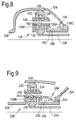
- Figure 9 shows an arrangement in which the low-pressure turbine 19 drives two fans indirectly via the shaft 226, a gearbox 228 and shaft 238A and 238B.
- the gearbox 228 comprises a sun gear 230, an annulus gear 232, a plurality of planet gears 234 and a planet gear carrier 236.
- the sun gear 230 meshes with the planet gears 234 and the planet gears 234 mesh with the annulus gear 232.
- the planet gear carrier 236 enabling each planet gear 234 to rotate about its own axis independently.
- the planet gear carrier 236 is coupled via the shaft 238A to a first propulsor (not shown) and the annulus gear 232 is coupled via the shaft 238B to a second propulsor (not shown) in order to drive their rotation about the engine axis 9.
- the propulsors are driven to rotate in opposite rotational directions.
- the axes of the planet gears 234 are parallel to the engine axis 9.
- the planet gear carrier 236 comprises a first ring 236A, a second ring 236B spaced axially from the first ring 236A and a plurality of circumferentially spaced axles 240 which extend axially between the first ring 236A and the second ring 236B.
- Each planet gear 234 is rotatably mounted on a respective one of the axles 240 and an annular extension 236C extends axially from the first ring 236A.
- Each planet gear 234 is rotatably mounted in the planet gear carrier 236 by at least one planet gear bearing 242.
- the annular extension 236C is rotatably mounted in the static structure 224 by a bearing 244.
- each planet gear 234 is rotatably mounted on the planet gear carrier 236 by two roller bearings 242.
- each planet gear 234 may be rotatably mounted on the planet gear carrier 236 by a journal bearing.
- a lubrication system 246 is arranged to supply lubricant to the planet gear bearings 242, the sun gear 230 and the planet gears 234.
- the gearbox arrangement 228 of figure 9 may be provided with a lubrication system 246 with an annular member 248 and an annular chamber 250 as described with reference to figures 4, 5 , 6 or 7 .
- the sun gear, the annulus gear, the planet gear carrier, or star gear carrier, and the shaft are coaxial.
- the lubricant e.g. oil
- the gas turbine engine comprises a propulsor, an intermediate-pressure compressor, a high-pressure compressor, a high-pressure turbine and a low-pressure turbine, the high-pressure turbine is arranged to directly drive the high-pressure compressor, the low-pressure turbine is arranged to directly drive the intermediate-pressure compressor and the low-pressure turbine is arranged to drive the propulsor via a gearbox.
- the gas turbine engine comprises a propulsor, an intermediate-pressure compressor, a high-pressure compressor, a high-pressure turbine and a low-pressure turbine, the high-pressure turbine is arranged to directly drive the high-pressure compressor, the low-pressure turbine is arranged to directly drive the propulsor and the low-pressure turbine is arranged to drive the intermediate-pressure compressor via a gearbox.
- the gas turbine engine comprises a propulsor, an intermediate-pressure compressor, a high-pressure compressor, a high-pressure turbine, an intermediate-pressure turbine and a low-pressure turbine
- the high-pressure turbine is arranged to directly drive the high-pressure compressor
- the intermediate-pressure turbine is arranged to directly drive the intermediate-pressure compressor
- the low-pressure turbine is arranged to drive the propulsor via a gearbox.
- the gas turbine engine may comprise a propulsor, a high-pressure compressor, a high-pressure turbine and a low-pressure turbine, the high-pressure turbine is arranged to directly drive the high-pressure compressor and the low-pressure turbine is arranged to drive the propulsor via a gearbox.
- the gas turbine engine comprises a first propulsor, a second propulsor, an intermediate-pressure compressor, a high-pressure compressor, a high-pressure turbine, an intermediate-pressure turbine and a low-pressure turbine
- the high-pressure turbine is arranged to directly drive the high-pressure compressor
- the intermediate-pressure turbine is arranged to directly drive the intermediate-pressure compressor
- the low-pressure turbine is arranged to drive the first propulsor and the second propulsor via a gearbox.
- the gas turbine engine comprises a first propulsor, a second propulsor, a low-pressure compressor, a high-pressure compressor, a high-pressure turbine, a low-pressure turbine and a free power turbine
- the high-pressure turbine is arranged to directly drive the high-pressure compressor
- the low-pressure turbine is arranged to directly drive the low-pressure compressor
- the free power turbine is arranged to drive the first propulsor and the second propulsor via a gearbox.
- the gas turbine engine comprises a first propulsor, a second propulsor, a low-pressure compressor, a high-pressure compressor, a high-pressure turbine and a low-pressure turbine
- the high-pressure turbine is arranged to directly drive the high-pressure compressor
- the low-pressure turbine is arranged to directly drive the low-pressure compressor
- the low-pressure turbine is arranged to drive the first propulsor and the second propulsor via a gearbox.
- the sun gear may be driven by a low-pressure turbine, the annulus gear may be secured to static structure and the planet gear carrier may be arranged to drive a propulsor.
- the sun gear may be driven by the low-pressure turbine, the planet gear carrier may be secured to static structure and the annulus gear may be arranged to drive a propulsor.
- the planet gears are termed star gears and the annular extension of the planet gear carrier is secured to the static structure.
- each planet gear rotates about its own axis and the planet gear carrier does not rotate about the engine axis.
- the axes of the planet gears are parallel to the engine axis.
- the planet gear carrier may be driven by the low-pressure turbine, the sun gear may be secured to static structure and the annulus gear may be arranged to drive a propulsor.
- the sun gear may be driven by the low-pressure turbine, the planet gear carrier may be arranged to drive a first propulsor and the annulus gear may be arranged to drive a second propulsor.
- the propulsor may be a fan or a propeller.
Applications Claiming Priority (1)
| Application Number | Priority Date | Filing Date | Title |
|---|---|---|---|
| GBGB1510050.6A GB201510050D0 (en) | 2015-06-10 | 2015-06-10 | A geared gas turbine engine |
Publications (3)
| Publication Number | Publication Date |
|---|---|
| EP3106714A2 true EP3106714A2 (fr) | 2016-12-21 |
| EP3106714A3 EP3106714A3 (fr) | 2017-02-15 |
| EP3106714B1 EP3106714B1 (fr) | 2018-03-14 |
Family
ID=53785225
Family Applications (1)
| Application Number | Title | Priority Date | Filing Date |
|---|---|---|---|
| EP16169749.5A Active EP3106714B1 (fr) | 2015-06-10 | 2016-05-16 | Moteur à turbine à gaz à engrenage |
Country Status (3)
| Country | Link |
|---|---|
| US (1) | US10794469B2 (fr) |
| EP (1) | EP3106714B1 (fr) |
| GB (1) | GB201510050D0 (fr) |
Cited By (4)
| Publication number | Priority date | Publication date | Assignee | Title |
|---|---|---|---|---|
| EP3495642A1 (fr) * | 2017-12-07 | 2019-06-12 | Rolls-Royce plc | Moteur à turbine à gaz |
| CN110506171A (zh) * | 2017-04-14 | 2019-11-26 | 赛峰航空器发动机 | 外摆线齿轮系的润滑 |
| US10914240B2 (en) | 2018-06-27 | 2021-02-09 | Rolls-Royce Plc | Gas turbine |
| WO2023036355A1 (fr) * | 2021-09-07 | 2023-03-16 | Schaeffler Technologies AG & Co. KG | Bac de collecte d'huile pour boîte de vitesses à trains planétaires |
Families Citing this family (14)
| Publication number | Priority date | Publication date | Assignee | Title |
|---|---|---|---|---|
| FR3013385B1 (fr) * | 2013-11-21 | 2015-11-13 | Snecma | Enceinte avant etanche lors du desassemblage modulaire d'un turboreacteur a reducteur |
| CN106255845B (zh) * | 2014-03-18 | 2018-11-02 | Ge亚飞欧有限责任公司 | 使润滑油从固定部分流至旋转部分的油转移组件 |
| JP6498559B2 (ja) * | 2015-07-31 | 2019-04-10 | 川崎重工業株式会社 | 遊星歯車装置への給油構造 |
| FR3062681B1 (fr) * | 2017-02-07 | 2020-11-20 | Safran Aircraft Engines | Turboreacteur a architecture de paliers optimisee pour le support d'un arbre basse pression |
| US10662879B2 (en) | 2017-08-08 | 2020-05-26 | Pratt & Whitney Canada Corp. | Epicyclic gear stage |
| FR3073915B1 (fr) * | 2017-11-17 | 2019-10-25 | Safran Transmission Systems | Cage de reducteur de vitesse a train planetaire ou epicycloidal de turbomachine |
| US10927944B2 (en) | 2018-01-26 | 2021-02-23 | Pratt & Whitney Canada Corp. | Compact, twist controlled planet carrier and epicyclic gear train having same |
| US10760677B2 (en) | 2018-01-31 | 2020-09-01 | Pratt & Whitney Canada Corp. | Epicyclic gear train with balanced carrier stiffness |
| US10711877B2 (en) * | 2018-02-23 | 2020-07-14 | General Electric Company | Passive lubrication system for gas turbine engine gearbox during wind milling |
| GB201819064D0 (en) | 2018-11-23 | 2019-01-09 | Rolls Royce | Aerofoil stagnation zone cooling |
| US10989073B2 (en) | 2019-03-05 | 2021-04-27 | Rolls-Royce Corporation | Power gearbox with embedded oil reservoir for use in a gas turbine engine |
| FR3095243B1 (fr) * | 2019-04-19 | 2021-04-30 | Safran Aircraft Engines | Reducteur de vitesse d’une turbomachine |
| CN113123876A (zh) * | 2019-12-30 | 2021-07-16 | 中国航发商用航空发动机有限责任公司 | 无涡轮后机匣构型航空发动机 |
| IT202000015064A1 (it) * | 2020-06-23 | 2021-12-23 | Ge Avio Srl | Gruppo ingranaggi per un motore aeronautico con tasche di stoccaggio di lubrificante |
Family Cites Families (24)
| Publication number | Priority date | Publication date | Assignee | Title |
|---|---|---|---|---|
| US4271928A (en) * | 1978-07-11 | 1981-06-09 | Rolls-Royce Limited | Lubricant supply device |
| DE3012846C2 (de) | 1980-04-02 | 1982-08-05 | Zahnradfabrik Friedrichshafen Ag, 7990 Friedrichshafen | Schmiereinrichtung für Planetenradlager |
| GB8630754D0 (en) | 1986-12-23 | 1987-02-04 | Rolls Royce Plc | Turbofan gas turbine engine |
| GB2199900B (en) | 1987-01-15 | 1991-06-19 | Rolls Royce Plc | A turbopropeller or turbofan gas turbine engine |
| GB2234035B (en) | 1989-07-21 | 1993-05-12 | Rolls Royce Plc | A reduction gear assembly and a gas turbine engine |
| EP1828573B1 (fr) | 2004-12-01 | 2010-06-16 | United Technologies Corporation | Joint hydraulique pour boite de vitesses de moteur a turbine d'extremite |
| US8267826B2 (en) | 2005-03-15 | 2012-09-18 | United Technologies Corporation | Uninterruptible oil supply in planetary system |
| US7704178B2 (en) | 2006-07-05 | 2010-04-27 | United Technologies Corporation | Oil baffle for gas turbine fan drive gear system |
| US8205432B2 (en) | 2007-10-03 | 2012-06-26 | United Technologies Corporation | Epicyclic gear train for turbo fan engine |
| DE102008000900A1 (de) | 2008-04-01 | 2009-10-08 | Zf Friedrichshafen Ag | Planetengetriebe |
| US8672801B2 (en) | 2009-11-30 | 2014-03-18 | United Technologies Corporation | Mounting system for a planetary gear train in a gas turbine engine |
| GB201005442D0 (en) | 2010-03-31 | 2010-05-19 | Rolls Royce Plc | Hydraulic fluid transfer coupling |
| US9995174B2 (en) * | 2010-10-12 | 2018-06-12 | United Technologies Corporation | Planetary gear system arrangement with auxiliary oil system |
| WO2013141931A1 (fr) | 2012-01-09 | 2013-09-26 | United Technologies Corporation | Moteur à turbine à gaz présentant une architecture à engrenages |
| FR2987417B1 (fr) | 2012-02-23 | 2014-03-28 | Snecma | Dispositif de recuperation de l'huile de lubrification d'un reducteur epicycloidal. |
| FR2987416B1 (fr) * | 2012-02-23 | 2015-09-04 | Snecma | Dispositif de lubrification d'un reducteur epicycloidal. |
| CN104204464B (zh) | 2012-03-23 | 2017-12-15 | 联合工艺公司 | 燃气涡轮发动机 |
| US8790075B2 (en) | 2012-03-30 | 2014-07-29 | United Technologies Corporation | Gas turbine engine geared architecture axial retention arrangement |
| US8484942B1 (en) | 2012-05-30 | 2013-07-16 | United Technologies Corporation | Planetary gear system arrangement with auxiliary oil system |
| JP6078160B2 (ja) | 2012-09-28 | 2017-02-08 | ユナイテッド テクノロジーズ コーポレイションUnited Technologies Corporation | ガスタービンファン駆動ギアシステムの組立方法 |
| EP2904250A4 (fr) | 2012-10-01 | 2015-10-21 | United Technologies Corp | Densité de puissance élevée de boîte de vitesses d'un turboréacteur double-flux à engrenages |
| GB201219544D0 (en) | 2012-10-31 | 2012-12-12 | Rolls Royce Deutschland | Geared compressor for gas turbine engine |
| GB201222203D0 (en) * | 2012-12-11 | 2013-01-23 | Rolls Royce Deutschland | Lubricant system |
| US10634237B2 (en) * | 2015-06-24 | 2020-04-28 | United Technologies Corporation | Lubricant delivery system for planetary fan drive gear system |
-
2015
- 2015-06-10 GB GBGB1510050.6A patent/GB201510050D0/en not_active Ceased
-
2016
- 2016-05-16 EP EP16169749.5A patent/EP3106714B1/fr active Active
- 2016-05-16 US US15/155,398 patent/US10794469B2/en active Active
Cited By (9)
| Publication number | Priority date | Publication date | Assignee | Title |
|---|---|---|---|---|
| CN110506171A (zh) * | 2017-04-14 | 2019-11-26 | 赛峰航空器发动机 | 外摆线齿轮系的润滑 |
| CN110506171B (zh) * | 2017-04-14 | 2024-03-15 | 赛峰航空器发动机 | 外摆线齿轮系的润滑 |
| EP3495642A1 (fr) * | 2017-12-07 | 2019-06-12 | Rolls-Royce plc | Moteur à turbine à gaz |
| US11015448B2 (en) | 2017-12-07 | 2021-05-25 | Rolls-Royce Plc | Gas turbine engine |
| US10914240B2 (en) | 2018-06-27 | 2021-02-09 | Rolls-Royce Plc | Gas turbine |
| US10920672B2 (en) | 2018-06-27 | 2021-02-16 | Rolls-Royce Plc | Gas turbine |
| US11187157B2 (en) | 2018-06-27 | 2021-11-30 | Rolls-Royce Plc | Gas turbine |
| US11454174B2 (en) | 2018-06-27 | 2022-09-27 | Rolls-Royce Plc | Gas turbine |
| WO2023036355A1 (fr) * | 2021-09-07 | 2023-03-16 | Schaeffler Technologies AG & Co. KG | Bac de collecte d'huile pour boîte de vitesses à trains planétaires |
Also Published As
| Publication number | Publication date |
|---|---|
| EP3106714B1 (fr) | 2018-03-14 |
| US10794469B2 (en) | 2020-10-06 |
| EP3106714A3 (fr) | 2017-02-15 |
| GB201510050D0 (en) | 2015-07-22 |
| US20160363211A1 (en) | 2016-12-15 |
Similar Documents
| Publication | Publication Date | Title |
|---|---|---|
| EP3106714B1 (fr) | Moteur à turbine à gaz à engrenage | |
| US11300007B2 (en) | Planetary gearbox having compliant journal bearings | |
| CN107013669B (zh) | 带有座圈内润滑设计的圆柱滚子轴承的行星齿轮箱 | |
| US10352195B2 (en) | Non-contacting seals for geared gas turbine engine bearing compartments | |
| EP2799674B1 (fr) | Système d'huile de lubrification pour réducteur de vitesse à engrenages | |
| US11486269B2 (en) | Gas turbine engine shaft bearing configuration | |
| EP2915962B1 (fr) | Soufflante à réducteur avec support frontal intégral | |
| US9726031B2 (en) | Piston ring coated carbon seal | |
| EP2925982B1 (fr) | Turbine à gaz à architecture à engrenages dotée d'un système de palier à rouleaux résistant au désalignement et à graissage amélioré | |
| EP3054139B1 (fr) | Système d'engrenage d'entraînement de soufflante | |
| US10066506B2 (en) | Reduced misalignment gear system | |
| EP3792472B1 (fr) | Moteur à turbine à gaz avec système d'engrenage d'entraînement de soufflante comprenant un arbre de soufflante en deux parties à récupération de fuite de transfert de lubrifiant | |
| EP3045772B2 (fr) | Moteur turbofan avec un système de transmission de couple divisé | |
| EP3020953B1 (fr) | Moteur à turbine à gaz | |
| GB2420381A (en) | Lubricating system for turbine engine. | |
| US10605352B2 (en) | Transfer bearing for geared turbofan | |
| US20160377166A1 (en) | Journal bearing for rotating gear carrier | |
| EP3001072B1 (fr) | Palier de transfert d'huile et méthode de transfert d'huile | |
| EP3825575B1 (fr) | Architecture à engrenages pour moteur à turbine à gaz |
Legal Events
| Date | Code | Title | Description |
|---|---|---|---|
| PUAI | Public reference made under article 153(3) epc to a published international application that has entered the european phase |
Free format text: ORIGINAL CODE: 0009012 |
|
| AK | Designated contracting states |
Kind code of ref document: A2 Designated state(s): AL AT BE BG CH CY CZ DE DK EE ES FI FR GB GR HR HU IE IS IT LI LT LU LV MC MK MT NL NO PL PT RO RS SE SI SK SM TR |
|
| AX | Request for extension of the european patent |
Extension state: BA ME |
|
| PUAL | Search report despatched |
Free format text: ORIGINAL CODE: 0009013 |
|
| AK | Designated contracting states |
Kind code of ref document: A3 Designated state(s): AL AT BE BG CH CY CZ DE DK EE ES FI FR GB GR HR HU IE IS IT LI LT LU LV MC MK MT NL NO PL PT RO RS SE SI SK SM TR |
|
| AX | Request for extension of the european patent |
Extension state: BA ME |
|
| RIC1 | Information provided on ipc code assigned before grant |
Ipc: F02C 7/36 20060101ALI20170111BHEP Ipc: F16H 57/04 20100101AFI20170111BHEP |
|
| 17P | Request for examination filed |
Effective date: 20170623 |
|
| RBV | Designated contracting states (corrected) |
Designated state(s): AL AT BE BG CH CY CZ DE DK EE ES FI FR GB GR HR HU IE IS IT LI LT LU LV MC MK MT NL NO PL PT RO RS SE SI SK SM TR |
|
| GRAP | Despatch of communication of intention to grant a patent |
Free format text: ORIGINAL CODE: EPIDOSNIGR1 |
|
| INTG | Intention to grant announced |
Effective date: 20170816 |
|
| GRAJ | Information related to disapproval of communication of intention to grant by the applicant or resumption of examination proceedings by the epo deleted |
Free format text: ORIGINAL CODE: EPIDOSDIGR1 |
|
| GRAP | Despatch of communication of intention to grant a patent |
Free format text: ORIGINAL CODE: EPIDOSNIGR1 |
|
| INTC | Intention to grant announced (deleted) | ||
| INTG | Intention to grant announced |
Effective date: 20171117 |
|
| GRAS | Grant fee paid |
Free format text: ORIGINAL CODE: EPIDOSNIGR3 |
|
| GRAA | (expected) grant |
Free format text: ORIGINAL CODE: 0009210 |
|
| AK | Designated contracting states |
Kind code of ref document: B1 Designated state(s): AL AT BE BG CH CY CZ DE DK EE ES FI FR GB GR HR HU IE IS IT LI LT LU LV MC MK MT NL NO PL PT RO RS SE SI SK SM TR |
|
| REG | Reference to a national code |
Ref country code: GB Ref legal event code: FG4D |
|
| REG | Reference to a national code |
Ref country code: CH Ref legal event code: EP Ref country code: AT Ref legal event code: REF Ref document number: 979217 Country of ref document: AT Kind code of ref document: T Effective date: 20180315 |
|
| REG | Reference to a national code |
Ref country code: IE Ref legal event code: FG4D |
|
| REG | Reference to a national code |
Ref country code: DE Ref legal event code: R096 Ref document number: 602016001950 Country of ref document: DE |
|
| REG | Reference to a national code |
Ref country code: FR Ref legal event code: PLFP Year of fee payment: 3 |
|
| REG | Reference to a national code |
Ref country code: NL Ref legal event code: MP Effective date: 20180314 |
|
| REG | Reference to a national code |
Ref country code: LT Ref legal event code: MG4D |
|
| PG25 | Lapsed in a contracting state [announced via postgrant information from national office to epo] |
Ref country code: FI Free format text: LAPSE BECAUSE OF FAILURE TO SUBMIT A TRANSLATION OF THE DESCRIPTION OR TO PAY THE FEE WITHIN THE PRESCRIBED TIME-LIMIT Effective date: 20180314 Ref country code: NO Free format text: LAPSE BECAUSE OF FAILURE TO SUBMIT A TRANSLATION OF THE DESCRIPTION OR TO PAY THE FEE WITHIN THE PRESCRIBED TIME-LIMIT Effective date: 20180614 Ref country code: CY Free format text: LAPSE BECAUSE OF FAILURE TO SUBMIT A TRANSLATION OF THE DESCRIPTION OR TO PAY THE FEE WITHIN THE PRESCRIBED TIME-LIMIT Effective date: 20180314 Ref country code: HR Free format text: LAPSE BECAUSE OF FAILURE TO SUBMIT A TRANSLATION OF THE DESCRIPTION OR TO PAY THE FEE WITHIN THE PRESCRIBED TIME-LIMIT Effective date: 20180314 Ref country code: LT Free format text: LAPSE BECAUSE OF FAILURE TO SUBMIT A TRANSLATION OF THE DESCRIPTION OR TO PAY THE FEE WITHIN THE PRESCRIBED TIME-LIMIT Effective date: 20180314 |
|
| REG | Reference to a national code |
Ref country code: AT Ref legal event code: MK05 Ref document number: 979217 Country of ref document: AT Kind code of ref document: T Effective date: 20180314 |
|
| PG25 | Lapsed in a contracting state [announced via postgrant information from national office to epo] |
Ref country code: LV Free format text: LAPSE BECAUSE OF FAILURE TO SUBMIT A TRANSLATION OF THE DESCRIPTION OR TO PAY THE FEE WITHIN THE PRESCRIBED TIME-LIMIT Effective date: 20180314 Ref country code: SE Free format text: LAPSE BECAUSE OF FAILURE TO SUBMIT A TRANSLATION OF THE DESCRIPTION OR TO PAY THE FEE WITHIN THE PRESCRIBED TIME-LIMIT Effective date: 20180314 Ref country code: BG Free format text: LAPSE BECAUSE OF FAILURE TO SUBMIT A TRANSLATION OF THE DESCRIPTION OR TO PAY THE FEE WITHIN THE PRESCRIBED TIME-LIMIT Effective date: 20180614 Ref country code: RS Free format text: LAPSE BECAUSE OF FAILURE TO SUBMIT A TRANSLATION OF THE DESCRIPTION OR TO PAY THE FEE WITHIN THE PRESCRIBED TIME-LIMIT Effective date: 20180314 Ref country code: GR Free format text: LAPSE BECAUSE OF FAILURE TO SUBMIT A TRANSLATION OF THE DESCRIPTION OR TO PAY THE FEE WITHIN THE PRESCRIBED TIME-LIMIT Effective date: 20180615 |
|
| PG25 | Lapsed in a contracting state [announced via postgrant information from national office to epo] |
Ref country code: RO Free format text: LAPSE BECAUSE OF FAILURE TO SUBMIT A TRANSLATION OF THE DESCRIPTION OR TO PAY THE FEE WITHIN THE PRESCRIBED TIME-LIMIT Effective date: 20180314 Ref country code: IT Free format text: LAPSE BECAUSE OF FAILURE TO SUBMIT A TRANSLATION OF THE DESCRIPTION OR TO PAY THE FEE WITHIN THE PRESCRIBED TIME-LIMIT Effective date: 20180314 Ref country code: EE Free format text: LAPSE BECAUSE OF FAILURE TO SUBMIT A TRANSLATION OF THE DESCRIPTION OR TO PAY THE FEE WITHIN THE PRESCRIBED TIME-LIMIT Effective date: 20180314 Ref country code: ES Free format text: LAPSE BECAUSE OF FAILURE TO SUBMIT A TRANSLATION OF THE DESCRIPTION OR TO PAY THE FEE WITHIN THE PRESCRIBED TIME-LIMIT Effective date: 20180314 Ref country code: AL Free format text: LAPSE BECAUSE OF FAILURE TO SUBMIT A TRANSLATION OF THE DESCRIPTION OR TO PAY THE FEE WITHIN THE PRESCRIBED TIME-LIMIT Effective date: 20180314 Ref country code: NL Free format text: LAPSE BECAUSE OF FAILURE TO SUBMIT A TRANSLATION OF THE DESCRIPTION OR TO PAY THE FEE WITHIN THE PRESCRIBED TIME-LIMIT Effective date: 20180314 Ref country code: PL Free format text: LAPSE BECAUSE OF FAILURE TO SUBMIT A TRANSLATION OF THE DESCRIPTION OR TO PAY THE FEE WITHIN THE PRESCRIBED TIME-LIMIT Effective date: 20180314 |
|
| PG25 | Lapsed in a contracting state [announced via postgrant information from national office to epo] |
Ref country code: AT Free format text: LAPSE BECAUSE OF FAILURE TO SUBMIT A TRANSLATION OF THE DESCRIPTION OR TO PAY THE FEE WITHIN THE PRESCRIBED TIME-LIMIT Effective date: 20180314 Ref country code: CZ Free format text: LAPSE BECAUSE OF FAILURE TO SUBMIT A TRANSLATION OF THE DESCRIPTION OR TO PAY THE FEE WITHIN THE PRESCRIBED TIME-LIMIT Effective date: 20180314 Ref country code: SK Free format text: LAPSE BECAUSE OF FAILURE TO SUBMIT A TRANSLATION OF THE DESCRIPTION OR TO PAY THE FEE WITHIN THE PRESCRIBED TIME-LIMIT Effective date: 20180314 Ref country code: SM Free format text: LAPSE BECAUSE OF FAILURE TO SUBMIT A TRANSLATION OF THE DESCRIPTION OR TO PAY THE FEE WITHIN THE PRESCRIBED TIME-LIMIT Effective date: 20180314 |
|
| REG | Reference to a national code |
Ref country code: DE Ref legal event code: R097 Ref document number: 602016001950 Country of ref document: DE |
|
| PG25 | Lapsed in a contracting state [announced via postgrant information from national office to epo] |
Ref country code: PT Free format text: LAPSE BECAUSE OF FAILURE TO SUBMIT A TRANSLATION OF THE DESCRIPTION OR TO PAY THE FEE WITHIN THE PRESCRIBED TIME-LIMIT Effective date: 20180716 |
|
| PLBE | No opposition filed within time limit |
Free format text: ORIGINAL CODE: 0009261 |
|
| STAA | Information on the status of an ep patent application or granted ep patent |
Free format text: STATUS: NO OPPOSITION FILED WITHIN TIME LIMIT |
|
| REG | Reference to a national code |
Ref country code: BE Ref legal event code: MM Effective date: 20180531 |
|
| PG25 | Lapsed in a contracting state [announced via postgrant information from national office to epo] |
Ref country code: MC Free format text: LAPSE BECAUSE OF FAILURE TO SUBMIT A TRANSLATION OF THE DESCRIPTION OR TO PAY THE FEE WITHIN THE PRESCRIBED TIME-LIMIT Effective date: 20180314 Ref country code: DK Free format text: LAPSE BECAUSE OF FAILURE TO SUBMIT A TRANSLATION OF THE DESCRIPTION OR TO PAY THE FEE WITHIN THE PRESCRIBED TIME-LIMIT Effective date: 20180314 |
|
| 26N | No opposition filed |
Effective date: 20181217 |
|
| REG | Reference to a national code |
Ref country code: IE Ref legal event code: MM4A |
|
| PG25 | Lapsed in a contracting state [announced via postgrant information from national office to epo] |
Ref country code: SI Free format text: LAPSE BECAUSE OF FAILURE TO SUBMIT A TRANSLATION OF THE DESCRIPTION OR TO PAY THE FEE WITHIN THE PRESCRIBED TIME-LIMIT Effective date: 20180314 |
|
| PG25 | Lapsed in a contracting state [announced via postgrant information from national office to epo] |
Ref country code: LU Free format text: LAPSE BECAUSE OF NON-PAYMENT OF DUE FEES Effective date: 20180516 |
|
| PG25 | Lapsed in a contracting state [announced via postgrant information from national office to epo] |
Ref country code: IE Free format text: LAPSE BECAUSE OF NON-PAYMENT OF DUE FEES Effective date: 20180516 |
|
| PG25 | Lapsed in a contracting state [announced via postgrant information from national office to epo] |
Ref country code: BE Free format text: LAPSE BECAUSE OF NON-PAYMENT OF DUE FEES Effective date: 20180531 |
|
| REG | Reference to a national code |
Ref country code: CH Ref legal event code: PL |
|
| PG25 | Lapsed in a contracting state [announced via postgrant information from national office to epo] |
Ref country code: LI Free format text: LAPSE BECAUSE OF NON-PAYMENT OF DUE FEES Effective date: 20190531 Ref country code: MT Free format text: LAPSE BECAUSE OF NON-PAYMENT OF DUE FEES Effective date: 20180516 Ref country code: CH Free format text: LAPSE BECAUSE OF NON-PAYMENT OF DUE FEES Effective date: 20190531 |
|
| PG25 | Lapsed in a contracting state [announced via postgrant information from national office to epo] |
Ref country code: TR Free format text: LAPSE BECAUSE OF FAILURE TO SUBMIT A TRANSLATION OF THE DESCRIPTION OR TO PAY THE FEE WITHIN THE PRESCRIBED TIME-LIMIT Effective date: 20180314 |
|
| PG25 | Lapsed in a contracting state [announced via postgrant information from national office to epo] |
Ref country code: HU Free format text: LAPSE BECAUSE OF FAILURE TO SUBMIT A TRANSLATION OF THE DESCRIPTION OR TO PAY THE FEE WITHIN THE PRESCRIBED TIME-LIMIT; INVALID AB INITIO Effective date: 20160516 Ref country code: MK Free format text: LAPSE BECAUSE OF NON-PAYMENT OF DUE FEES Effective date: 20180314 |
|
| PG25 | Lapsed in a contracting state [announced via postgrant information from national office to epo] |
Ref country code: IS Free format text: LAPSE BECAUSE OF FAILURE TO SUBMIT A TRANSLATION OF THE DESCRIPTION OR TO PAY THE FEE WITHIN THE PRESCRIBED TIME-LIMIT Effective date: 20180714 |
|
| P01 | Opt-out of the competence of the unified patent court (upc) registered |
Effective date: 20230528 |
|
| PGFP | Annual fee paid to national office [announced via postgrant information from national office to epo] |
Ref country code: FR Payment date: 20230523 Year of fee payment: 8 Ref country code: DE Payment date: 20230530 Year of fee payment: 8 |
|
| PGFP | Annual fee paid to national office [announced via postgrant information from national office to epo] |
Ref country code: GB Payment date: 20230523 Year of fee payment: 8 |