EP3106325B1 - Pneumatisches system zum befüllen eines reifens, das in eine motorisierte achse integriert ist - Google Patents
Pneumatisches system zum befüllen eines reifens, das in eine motorisierte achse integriert ist Download PDFInfo
- Publication number
- EP3106325B1 EP3106325B1 EP16174637.5A EP16174637A EP3106325B1 EP 3106325 B1 EP3106325 B1 EP 3106325B1 EP 16174637 A EP16174637 A EP 16174637A EP 3106325 B1 EP3106325 B1 EP 3106325B1
- Authority
- EP
- European Patent Office
- Prior art keywords
- bearing support
- seal
- chamber
- shaft
- bearing
- Prior art date
- Legal status (The legal status is an assumption and is not a legal conclusion. Google has not performed a legal analysis and makes no representation as to the accuracy of the status listed.)
- Active
Links
Images








Classifications
-
- B—PERFORMING OPERATIONS; TRANSPORTING
- B60—VEHICLES IN GENERAL
- B60C—VEHICLE TYRES; TYRE INFLATION; TYRE CHANGING; CONNECTING VALVES TO INFLATABLE ELASTIC BODIES IN GENERAL; DEVICES OR ARRANGEMENTS RELATED TO TYRES
- B60C23/00—Devices for measuring, signalling, controlling, or distributing tyre pressure or temperature, specially adapted for mounting on vehicles; Arrangement of tyre inflating devices on vehicles, e.g. of pumps or of tanks; Tyre cooling arrangements
- B60C23/001—Devices for manually or automatically controlling or distributing tyre pressure whilst the vehicle is moving
-
- B—PERFORMING OPERATIONS; TRANSPORTING
- B60—VEHICLES IN GENERAL
- B60C—VEHICLE TYRES; TYRE INFLATION; TYRE CHANGING; CONNECTING VALVES TO INFLATABLE ELASTIC BODIES IN GENERAL; DEVICES OR ARRANGEMENTS RELATED TO TYRES
- B60C23/00—Devices for measuring, signalling, controlling, or distributing tyre pressure or temperature, specially adapted for mounting on vehicles; Arrangement of tyre inflating devices on vehicles, e.g. of pumps or of tanks; Tyre cooling arrangements
- B60C23/001—Devices for manually or automatically controlling or distributing tyre pressure whilst the vehicle is moving
- B60C23/003—Devices for manually or automatically controlling or distributing tyre pressure whilst the vehicle is moving comprising rotational joints between vehicle-mounted pressure sources and the tyres
- B60C23/00309—Devices for manually or automatically controlling or distributing tyre pressure whilst the vehicle is moving comprising rotational joints between vehicle-mounted pressure sources and the tyres characterised by the location of the components, e.g. valves, sealings, conduits or sensors
- B60C23/00318—Devices for manually or automatically controlling or distributing tyre pressure whilst the vehicle is moving comprising rotational joints between vehicle-mounted pressure sources and the tyres characterised by the location of the components, e.g. valves, sealings, conduits or sensors on the wheels or the hubs
-
- B—PERFORMING OPERATIONS; TRANSPORTING
- B60—VEHICLES IN GENERAL
- B60C—VEHICLE TYRES; TYRE INFLATION; TYRE CHANGING; CONNECTING VALVES TO INFLATABLE ELASTIC BODIES IN GENERAL; DEVICES OR ARRANGEMENTS RELATED TO TYRES
- B60C23/00—Devices for measuring, signalling, controlling, or distributing tyre pressure or temperature, specially adapted for mounting on vehicles; Arrangement of tyre inflating devices on vehicles, e.g. of pumps or of tanks; Tyre cooling arrangements
- B60C23/001—Devices for manually or automatically controlling or distributing tyre pressure whilst the vehicle is moving
- B60C23/003—Devices for manually or automatically controlling or distributing tyre pressure whilst the vehicle is moving comprising rotational joints between vehicle-mounted pressure sources and the tyres
- B60C23/00345—Details of the rotational joints
-
- B—PERFORMING OPERATIONS; TRANSPORTING
- B60—VEHICLES IN GENERAL
- B60C—VEHICLE TYRES; TYRE INFLATION; TYRE CHANGING; CONNECTING VALVES TO INFLATABLE ELASTIC BODIES IN GENERAL; DEVICES OR ARRANGEMENTS RELATED TO TYRES
- B60C23/00—Devices for measuring, signalling, controlling, or distributing tyre pressure or temperature, specially adapted for mounting on vehicles; Arrangement of tyre inflating devices on vehicles, e.g. of pumps or of tanks; Tyre cooling arrangements
- B60C23/001—Devices for manually or automatically controlling or distributing tyre pressure whilst the vehicle is moving
- B60C23/003—Devices for manually or automatically controlling or distributing tyre pressure whilst the vehicle is moving comprising rotational joints between vehicle-mounted pressure sources and the tyres
- B60C23/00363—Details of sealings
-
- B—PERFORMING OPERATIONS; TRANSPORTING
- B60—VEHICLES IN GENERAL
- B60C—VEHICLE TYRES; TYRE INFLATION; TYRE CHANGING; CONNECTING VALVES TO INFLATABLE ELASTIC BODIES IN GENERAL; DEVICES OR ARRANGEMENTS RELATED TO TYRES
- B60C23/00—Devices for measuring, signalling, controlling, or distributing tyre pressure or temperature, specially adapted for mounting on vehicles; Arrangement of tyre inflating devices on vehicles, e.g. of pumps or of tanks; Tyre cooling arrangements
- B60C23/001—Devices for manually or automatically controlling or distributing tyre pressure whilst the vehicle is moving
- B60C23/003—Devices for manually or automatically controlling or distributing tyre pressure whilst the vehicle is moving comprising rotational joints between vehicle-mounted pressure sources and the tyres
- B60C23/0039—Devices for manually or automatically controlling or distributing tyre pressure whilst the vehicle is moving comprising rotational joints between vehicle-mounted pressure sources and the tyres specially adapted for driven wheels
-
- F—MECHANICAL ENGINEERING; LIGHTING; HEATING; WEAPONS; BLASTING
- F16—ENGINEERING ELEMENTS AND UNITS; GENERAL MEASURES FOR PRODUCING AND MAINTAINING EFFECTIVE FUNCTIONING OF MACHINES OR INSTALLATIONS; THERMAL INSULATION IN GENERAL
- F16C—SHAFTS; FLEXIBLE SHAFTS; ELEMENTS OR CRANKSHAFT MECHANISMS; ROTARY BODIES OTHER THAN GEARING ELEMENTS; BEARINGS
- F16C33/00—Parts of bearings; Special methods for making bearings or parts thereof
- F16C33/72—Sealings
- F16C33/726—Sealings with means to vent the interior of the bearing
-
- B—PERFORMING OPERATIONS; TRANSPORTING
- B60—VEHICLES IN GENERAL
- B60B—VEHICLE WHEELS; CASTORS; AXLES FOR WHEELS OR CASTORS; INCREASING WHEEL ADHESION
- B60B27/00—Hubs
- B60B27/0047—Hubs characterised by functional integration of other elements
-
- B—PERFORMING OPERATIONS; TRANSPORTING
- B60—VEHICLES IN GENERAL
- B60B—VEHICLE WHEELS; CASTORS; AXLES FOR WHEELS OR CASTORS; INCREASING WHEEL ADHESION
- B60B27/00—Hubs
- B60B27/0073—Hubs characterised by sealing means
-
- B—PERFORMING OPERATIONS; TRANSPORTING
- B60—VEHICLES IN GENERAL
- B60K—ARRANGEMENT OR MOUNTING OF PROPULSION UNITS OR OF TRANSMISSIONS IN VEHICLES; ARRANGEMENT OR MOUNTING OF PLURAL DIVERSE PRIME-MOVERS IN VEHICLES; AUXILIARY DRIVES FOR VEHICLES; INSTRUMENTATION OR DASHBOARDS FOR VEHICLES; ARRANGEMENTS IN CONNECTION WITH COOLING, AIR INTAKE, GAS EXHAUST OR FUEL SUPPLY OF PROPULSION UNITS IN VEHICLES
- B60K7/00—Disposition of motor in, or adjacent to, traction wheel
- B60K7/0015—Disposition of motor in, or adjacent to, traction wheel the motor being hydraulic
-
- F—MECHANICAL ENGINEERING; LIGHTING; HEATING; WEAPONS; BLASTING
- F16—ENGINEERING ELEMENTS AND UNITS; GENERAL MEASURES FOR PRODUCING AND MAINTAINING EFFECTIVE FUNCTIONING OF MACHINES OR INSTALLATIONS; THERMAL INSULATION IN GENERAL
- F16C—SHAFTS; FLEXIBLE SHAFTS; ELEMENTS OR CRANKSHAFT MECHANISMS; ROTARY BODIES OTHER THAN GEARING ELEMENTS; BEARINGS
- F16C19/00—Bearings with rolling contact, for exclusively rotary movement
- F16C19/54—Systems consisting of a plurality of bearings with rolling friction
- F16C19/546—Systems with spaced apart rolling bearings including at least one angular contact bearing
- F16C19/547—Systems with spaced apart rolling bearings including at least one angular contact bearing with two angular contact rolling bearings
- F16C19/548—Systems with spaced apart rolling bearings including at least one angular contact bearing with two angular contact rolling bearings in O-arrangement
-
- F—MECHANICAL ENGINEERING; LIGHTING; HEATING; WEAPONS; BLASTING
- F16—ENGINEERING ELEMENTS AND UNITS; GENERAL MEASURES FOR PRODUCING AND MAINTAINING EFFECTIVE FUNCTIONING OF MACHINES OR INSTALLATIONS; THERMAL INSULATION IN GENERAL
- F16C—SHAFTS; FLEXIBLE SHAFTS; ELEMENTS OR CRANKSHAFT MECHANISMS; ROTARY BODIES OTHER THAN GEARING ELEMENTS; BEARINGS
- F16C2326/00—Articles relating to transporting
- F16C2326/01—Parts of vehicles in general
- F16C2326/02—Wheel hubs or castors
-
- F—MECHANICAL ENGINEERING; LIGHTING; HEATING; WEAPONS; BLASTING
- F16—ENGINEERING ELEMENTS AND UNITS; GENERAL MEASURES FOR PRODUCING AND MAINTAINING EFFECTIVE FUNCTIONING OF MACHINES OR INSTALLATIONS; THERMAL INSULATION IN GENERAL
- F16C—SHAFTS; FLEXIBLE SHAFTS; ELEMENTS OR CRANKSHAFT MECHANISMS; ROTARY BODIES OTHER THAN GEARING ELEMENTS; BEARINGS
- F16C33/00—Parts of bearings; Special methods for making bearings or parts thereof
- F16C33/30—Parts of ball or roller bearings
- F16C33/66—Special parts or details in view of lubrication
- F16C33/6603—Special parts or details in view of lubrication with grease as lubricant
-
- F—MECHANICAL ENGINEERING; LIGHTING; HEATING; WEAPONS; BLASTING
- F16—ENGINEERING ELEMENTS AND UNITS; GENERAL MEASURES FOR PRODUCING AND MAINTAINING EFFECTIVE FUNCTIONING OF MACHINES OR INSTALLATIONS; THERMAL INSULATION IN GENERAL
- F16C—SHAFTS; FLEXIBLE SHAFTS; ELEMENTS OR CRANKSHAFT MECHANISMS; ROTARY BODIES OTHER THAN GEARING ELEMENTS; BEARINGS
- F16C33/00—Parts of bearings; Special methods for making bearings or parts thereof
- F16C33/30—Parts of ball or roller bearings
- F16C33/66—Special parts or details in view of lubrication
- F16C33/6637—Special parts or details in view of lubrication with liquid lubricant
-
- F—MECHANICAL ENGINEERING; LIGHTING; HEATING; WEAPONS; BLASTING
- F16—ENGINEERING ELEMENTS AND UNITS; GENERAL MEASURES FOR PRODUCING AND MAINTAINING EFFECTIVE FUNCTIONING OF MACHINES OR INSTALLATIONS; THERMAL INSULATION IN GENERAL
- F16C—SHAFTS; FLEXIBLE SHAFTS; ELEMENTS OR CRANKSHAFT MECHANISMS; ROTARY BODIES OTHER THAN GEARING ELEMENTS; BEARINGS
- F16C43/00—Assembling bearings
- F16C43/04—Assembling rolling-contact bearings
Definitions
- the invention relates to pneumatic supply systems for controlling and inflating the inflation state of vehicle wheels. More particularly, the invention relates to such systems in the motorized wheel frame locally by a rotating shaft hydraulic machine.
- Wheel inflation adjustment is common in agricultural machinery or construction machinery to increase or decrease the ground contact area.
- FR 2 895 470 A1 discloses such a system for known wheel pneumatic supply, comprising a bearing bearing set, disposed between a bearing support and a hub for the rotation of said hub in the bearing bracket about a longitudinal axis.
- the invention aims to allow the supply of compressed air of a tire mounted on a rim of the vehicle.
- the chamber allows fluid communication between rotating parts and fixed parts.
- the joints allow the creation of such a sealed chamber.
- the two channels serve to transmit the compressed air from the fixed bearing support to the rotating rim.
- the invention proposes a vehicle comprising an assembly as described above.
- Said vehicles may be road vehicles, but also agricultural machinery or public works machinery, and, in the broad sense, all machines having a wheel (for example trucks, etc.) and which comprise an air supply compressed a tire mounted on a rim.
- a system 1 comprising a bearing support 10 and a shaft 20 which extends along a longitudinal axis X and which comprises a hub end 21.
- the bearing support 10 has a general shape of revolution within which the shaft 20 is rotatable.
- the hub end 21 makes it possible to attach a wheel rim 2a carrying a tire 2b.
- the end 21 forming a hub extends radially, that is to say it has a dimension in a radial direction Y, orthogonal to the longitudinal axis X, greater than one dimension of the shaft 20 (outside the end 21 forming a hub) in the same direction Y.
- the system is mounted on a vehicle, for example an agricultural or construction vehicle, equipped with rims 2a each carrying a tire 2b.
- the tire 2b can be inflated to different pressures.
- the inflation of the tire 2b is done by an air inlet at the rim.
- Compressed air supply means 5 can supply the system with compressed air, as will be detailed later.
- the shaft 20 is rotated along the longitudinal axis X relative to the bearing support 10. It is thus defined that the bearing support 10 is fixed. By fixed, we therefore mean relative to a vehicle reference. However, even if the bearing support 10 does not perform rotation related to the movement of the vehicle, it can be mobile in a frame linked to the vehicle when teaming a directional wheel. At least one bearing race is provided between the bearing support 10 and the shaft 20.
- the bearing comprises rolling tracks and rolling elements on these tracks, such as rollers, balls or any other equivalent means.
- the rolling elements can be housed in cages to keep them in position.
- tapered rollers 30 bear on two tracks 31, 32, one secured to the support of Bearing 10 and the other of the shaft 20.
- the rollers of the bearing are typically housed in cages 33.
- the bearing bearing set 30 is typically lubricated with grease. Grease provides better lubrication than oil. It works better at high contact pressures, and allows longer bearing life for very high loads on the bearings. Alternatively, to simplify the architecture of the system, the bearing bearing set 30 can be lubricated with oil.
- a second set of bearing bearings 35 may be provided to form an "O" or "X" mount.
- This game 35 also has its own tracks of bearings.
- An inter-rolling joint 36 can separate the two sets of bearings 30, 35 to allow each to have its own lubrication.
- the second set 35 can be lubricated with oil from a hydraulic machine.
- bearings can be lubricated with oil, or with grease, or in a mixed way, some with oil and some with grease in the same machine. Be that as it may, bearings that are lubricated with grease must be separated from the oil contained in a housing of the hydraulic machine 96 (see figure 1 , 13 ) by a joint.
- the tracks of the bearings 30 or 35 can be made in one piece with the bearing support 10 or the shaft 20. Longitudinally, these elements are arranged in the following order: end 21 forming a hub, the bearing set 30 , the inter-rolling seal 36, the second set of bearings 35, then the hydraulic machine 3.
- the shaft 20 is preferably rotated by a hydraulic machine 3.
- the hydraulic machine 3 will be presented at the end of the description.
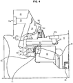
- the system 1 furthermore comprises a chamber C formed by the end 21 forming a hub, the bearing support 10 and two joints: a rolling joint 40 and a chamber seal 50 ( figures 2 , 3 ).
- This chamber C formed between rotating parts and fixed (non-rotating) parts, makes it possible to perform the interface in the compressed air transmission system from the means for supplying compressed air 5 to the rim 2a ( figure 1 ).
- a primary channel 60 is provided, which passes through the bearing support 10 to open into the chamber C.
- This primary channel 60 comprises an inlet orifice 60a, opening on the outer radial surface of the bearing support 10, on which connect a pipe 4 connected to the compressed air supply means 5 ( figure 1 ). Since the inlet port 60a is on the bearing support 10, it is fixed and can therefore be supplied without difficulty with compressed air. The compressed air is thus injected into the sealed chamber C through the joints 40, 50.
- a secondary channel 70 is also provided, which passes through the end 21 forming a hub to open into the chamber C.
- This secondary channel 70 comprises an outlet orifice 70a configured to open into the portion of the end 21 forming a hub, which is located substantially in the center or in the central part of the rim 2a ( figure 1 ).
- the outlet orifice 70a contains in a known manner sealing and fixing surfaces, typically a thread, for receiving a connection to the tire 2b via the rim. Since the outlet port 70a is on the rotating hub end 21, the function of the chamber C is to provide a fluid connection between the stationary members of the system and the rotating members.
- An inflation control valve system may be attached to the outlet port 70a to control the flow of air to the tire.
- An inflation orifice (not shown in the figures) present in the rim makes it possible to put the interior of the tire into communication with the outlet orifice 70a, in particular via the inflation control valve, using, for example, a pipe (not shown in the figures).
- This pipe may be rigid and formed along its path, or flexible, or have a rigid portion and a flexible portion.
- the control valve may be located anywhere on the air transmission chain between the outlet port 70a of the secondary channel 70 and the inflation port. The fluidic communications are then ensured either by direct fastening or by flexible hoses.
- the seal is provided by the seals 40, 50 which close the chamber C.
- the two seals 40, 50 are in the form of a circular seal.
- the chamber C has a section along a plane orthogonal to the longitudinal axis X ring-shaped, or according to the chosen plane, of several concentric rings.
- the bearing seal 40 is in contact with both the bearing support 10 and the shaft 20, to seal the cavity C during the rotation of the shaft 20.
- the chamber seal 50 seals the cavity C at the end 21 forming the hub and the bearing support 10.
- the bearing support 10 comprises an end 11 and the end 21 forming a hub comprises a longitudinal extension 22 which comes longitudinally opposite the end 11 of the bearing support 10.
- end 11 of the bearing support 10 is radially located between the shaft 20 and the longitudinal extension 22 of the end 21 forming a hub.
- the end 11 of the bearing support 20 has a cylindrical barrel shape which is housed inside a circular groove formed in the end 11 forming a hub.
- the groove which comprises an inner radial face 21a, an axial face 22b and an outer radial face 21c, opens on the bearing support 20.
- the chamber seal 50 is advantageously positioned between the end 11 of the bearing support 10, that is to say on the outer radial face 21c and the longitudinal extension 22. It ensures the sealing of the cavity C between the longitudinal extension 22 rotating and the end 11 of the bearing support 10 fixed (non-rotating).
- the two seals 40, 50 are located in the same radial plane or substantially in the same radial plane, that is to say in the same or substantially in the same plane orthogonal to the longitudinal axis.
- a sectional view of the system presented in figure 5 (figure not to scale) found in a same plane, orthogonal to the longitudinal axis X, the shaft 20, the bearing seal 40, the end 11 of the bearing support 10, the chamber seal 50 and the longitudinal extension 22.
- the seals 40, 50 are radially framed by the shaft 20 and the bearing support 10, or the shaft 20 and the longitudinal extension 22.
- substantially in the same plane is meant that there is a radial sectional plane in which the two joints are visible.
- a seal holder 44 of the hoop type can be disposed between the bearing seal 40 and the bearing support 10 and a wedging support 45 can be disposed between said seal 40 and the shaft 20 (inner radial face 21a).
- a shim 46 can be arranged in the chamber C, in contact with the chamber gasket C, to lock it longitudinally.
- Gaskets 40, 50 are ring-like lip, which are adapted for rotating parts.
- the seals 40, 50 each comprise a liner 41, 51 in fixed contact respectively with the shaft 20 and the end 21 forming a hub (or the joint support 41 if appropriate), and a lip 42, 52, which is in friction with the bearing support 10 (or the seal support 41 if appropriate) and allows the sealing of the cavity C despite the rotation.
- the two seals 40, 50 are integral with the rotating parts and are therefore rotated relative to the bearing support 10. This embodiment is convenient for assembly and assembly of the machine. Nevertheless, one of the two seals 40, 50 may not be rotating (see figure 2 for example) and be integral with the bearing support 10.
- the gasket and the sealing lip are interconnected by a finer intermediate portion offset on one of the edges of the gasket and the lip, thereby defining a hollow portion at the opposite edge between the gasket and the lip.
- This hollow part forms, in a sectional plane shown in the figures, a C.
- the hollow portion faces the chamber C, according to another embodiment, the hollow portion faces the bearings.
- a protective ring can be combined with each lip seal.
- the primary channel 60 comprises a rectilinear channel portion 61 which extends longitudinally or substantially longitudinally with respect to the longitudinal axis X in the bearing support end 11.
- the channel portion 61 opens in room C.
- a straight duct 62 is provided in order to be able to connect the channel portion 61 to the inlet orifice 60a.
- the latter extends radially, or substantially radially, ie orthogonal or substantially orthogonal to the longitudinal axis X.
- the inlet orifice 60a contains unrepresented fastening means, for example a thread and sealing means, for connecting it to the pipe 4 in a known manner.
- the arrangement of the primary channel 60 in a rectilinear channel portion 61 and a rectilinear conduit 62 which intersect in the bearing support 10 allows their formation in the bearing support 10 by simple drilling.
- the length of the primary channel 60 is preferably minimal. By using drilling, it is not necessary to modify the foundry molds.
- the primary channel 60 may include a second channel portion 63 fluidly in parallel to that mentioned previously.
- the two channel portions 61, 63 open into the cavity C and are then spaced a distance smaller than the diameter of the duct 62, in order to also open into the duct 62.
- the communication is made by intersection of several cylinders corresponding to the portions 61, 63 and leads 62.
- the two portions 61, 63 are geometrically parallel. Having two channel portions 61, 63 makes it possible to reduce their diameter compared to a single portion 61, for a constant air flow.
- the bearing support 10 is a part subjected to strong stresses (it bears in particular the weight of the vehicle) and it may be desirable to minimize the volume of each recess.
- having two channel portions 61, 63 makes it possible to limit the recess of material radially. This makes it possible to have a bearing support part 10 which is stronger or thinner to pass the necessary air flow.
- An attachment zone 23 is defined on the end 21 forming a hub (see FIG. figure 1 ).
- This zone corresponds to a radial plane area (relative to the longitudinal axis X) of the hub on which the rim 2a is secured.
- a set of bolts 24 regularly distributed in a ring traversed at its center by the longitudinal axis X.
- the secondary channel 70 can be in the form of a rectilinear channel extending longitudinally or substantially longitudinally along the longitudinal axis X.
- the orifice of 70a of the channel 70 is located radially between the longitudinal axis X and the attachment zone 23.
- the secondary channel 70 can be in the form of a rectilinear channel extending obliquely diverging radially with respect to the longitudinal axis X to open at the attachment zone 23, that is to say that the outlet orifice 70a is in this zone 23.
- a recess 25 is formed in the attachment zone 23 to allow the outlet orifice 70a to be in the extension of the rectilinear channel 70 without being in the zone plane of the fastening area 23.
- bias means that in a cutting plane comprising the longitudinal axis X, the channel extends at an angle between 10 and 80 °, and more precisely between 30 and 60 °.
- the secondary channel 70 may comprise a first portion 71 extending longitudinally from the fastening region 23. 70a outlet is in the radial plane area of the attachment region
- the secondary channel 70 also includes a second portion 72 which connects the first portion 71 to the chamber C.
- the second portion 72 passes through the hub end 21 to the chamber C, joining the first portion 71 in said end 21 hub.
- An inner radial end of said portion 72 thus opens into the chamber C and an outer radial end of said portion 72 opens onto an outer radial surface of the end 11 forming a hub, said second portion 72 being intersecting with the first portion 71.
- the portions are preferably made by drilling, not by foundry molding.
- the portions are preferably rectilinear.
- the second portion 72 may be biased relative to the longitudinal extension X or orthogonal.
- a plug 73 is provided at the outer radial end of the second portion 72 to seal the secondary channel 70 and allow the compressed air of the chamber C to reach the outlet 70a.
- the primary and secondary channels are preferably never aligned, so as to avoid a direct flow of air and maintain a buffer role of the cavity C, to possibly absorb transient overpressures.
- the channel portion 61 and the secondary channel 70 extend rectilinearly parallel to the longitudinal axis X, they are arranged at different radial distances.
- a protective seal 80 may be provided.
- the chamber seal 50 is located between the chamber C and the seal 80 which prevents water, dust, etc. to come into contact with said chamber seal 50.
- the protective seal 80 is positioned radially between the bearing support 10 and the longitudinal extension 22 to protect the chamber seal 50 ( figure 2 ). This is typically a lip seal ring, already used in bearings to protect them from the outside environment. The protective seal 80 is fixed.
- a sheet metal gasket 81 is positioned radially outwardly on the bearing support 10 and extends toward the extension 22 to partially cover it without touching it. This sheet 81 makes it possible to protect the direct shine protection seal.
- the seals 40, 50 have some leaks, favored when the compressed air supply means 5 malfunction and cause overpressures in the chamber C. The seals could then jump from their housing or tear, making thus to pass dirt in the fat.
- the inter-rolling joint 36 is damaged, there would be a risk of grease leakage to the crankcase of the engine lubricated with oil.
- the inter-rolling joint 36 is in fluid communication with the volume between the rolling joint 40 and the first bearing set 30.
- a device is provided to allow atmospheric pressure to be put on the volumes around the seals 40, 50, as well as the volume around the bearings 30, 35.
- a first bore 82 may be provided in the longitudinal extension 22.
- This bore 82 from an outer surface to the end 21 forming a hub opens between the chamber seal 50 and the protective seal 80.
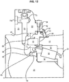
- a second hole 83 may be provided in the end 11 of the bearing support 10, and, where appropriate the fretted seal holder 44, in order to open into the region around the bearings 30.
- a fluid communication 82, 83 is then provided between this region and the outside which is at atmospheric pressure, via the two holes 82, 83.
- the drilling 83 in the bearing support 10 and in the hoop 44 is not necessarily straight, that is to say that there may be an offset, for example if there is a volume in the form of a circular groove , or groove, between the hoop 44 and the bearing support 10.
- Said groove can be made in the hoop or in the bearing support 10. In a known manner this groove communicates the bore in the end 11 of the support of bearing 10 and the drilling in the band 44, even if they are not face to face radially, and to a lesser extent axially.
- a valve 84 which serves as a non-return valve, closes the first bore 82 to both allow the evacuation of overpressure but also prevent dirt from entering through the first bore 82.
- the valve 84 is calibrated to the desired pressure . In particular, the calibration of the valve 84 is sufficiently small so that the pressure of deterioration of the joints, especially the inter-rolling seal 36 is not reached.
- the second hole 83 is made in another plane than the latter, so that there is no fluid communication between the primary channel 60 and the second hole 83.
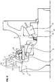
- the figure 11 is a sectional view in the plane of the primary channel 60, therefore, the second hole 83 is not visible.
- the figure 12 represents a sectional view of the bearing support 10 in the plane of the bore 83.
- the pipe 4 is preferably flexible since the bearing supports 10 can be part of a directional wheel (typically the front wheels of a vehicle), or a wheel movable relative to the chassis, thanks to a suspension system.
- a directional wheel typically the front wheels of a vehicle
- a wheel movable relative to the chassis thanks to a suspension system.
- the machine shaft 95 can be integral in rotation with the shaft 20 or, as is the case in the figures, form a single piece with the shaft 20.
- the bearing supports 10 are typically integral with the housing and / or the cover.
- a gear reducer can be placed between the block and the output shaft.
- the hydraulic machine is preferably a hydraulic machine called fast axial piston, or a radial piston machine and cam with a single lobe. In this case the machine turns faster than the wheels.
- the bearing support 10 is equipped with the running track 31 integral with the bearing support 10. This track 31 can be held in place by the seal holder 44 of the hoop type.
- the metal seal 81 and the protective seal 80 are placed, as well as the inter-rolling seal 36.
- the bearing support 10 is placed on the shaft 20 thus equipped.
- the tracks of the second bearing set 35 can then be put in place.
- a wedge 37 and an elastic ring 38 are placed in an annular groove extending on a periphery of the shaft (not shown) outside the bearings 30, 35.
- the wedge 37 and the elastic ring 38 are longitudinally between the machine 3 and the bearings 30, 35.
- the holding of the machine shaft 95, or the shaft 20 according to the embodiments, in the hydraulic machine 3 is thus improved.
- the shaft 20 comprises longitudinal splines ("spline shaft") to achieve the torque transmission between the cylinder block 93 and the shaft 20, 90, the groove is machined transversely to these grooves.
Landscapes
- Engineering & Computer Science (AREA)
- Mechanical Engineering (AREA)
- General Engineering & Computer Science (AREA)
- Rolling Contact Bearings (AREA)
Claims (16)
- System für die pneumatische Radversorgung, umfassend:- einen Lagerbock (10),- eine Welle (20), die sich gemäß einer Längsachse (X) im Innern des Lagerbocks (10) erstreckt und ein Ende (21) umfasst, das eine Nabe bildet, die sich radial erstreckt (Y), wobei die Welle konfiguriert ist, um von einer Hydraulikmaschine rotierend angetrieben zu sein,- mindestens ein Wälzlagerset (30), das zwischen dem Lagerbock (10) und der Welle (20) für die Rotation der Welle im Lagerbock um die Längsachse angeordnet ist, wobei das System ferner umfasst:- eine Kammer (C), gebildet von dem Ende (21), das eine Nabe bildet, dem Lagerbock (10), einer Lagerdichtung (40) und einer Kammerdichtung (50),- einen primären Kanal (60), der den Lagerbock (10) durchquert und in die Kammer (C) ausmündet,- einen sekundären Kanal (70), der das Ende (21) durchquert, das eine Nabe bildet, und in der Kammer (C) ausmündet,wobei:- die Lagerdichtung (40), die längs zwischen dem Wälzlagerset (30) und der Kammer (C) angeordnet ist, im Kontakt mit dem Lagerbock (10) und der Welle (20) ist, um die Dichtigkeit zwischen der Welle (20), die konfiguriert ist, um rotierend beweglich zu sein, und dem Lagerbock (10), der konfiguriert ist, um fest zu sein, zu sichern,- die Kammerdichtung (50) im Kontakt mit dem Lagerbock (10) und dem Ende (21), das eine Nabe bildet, ist, um die Dichtigkeit zwischen dem Ende (21), das eine Nabe bildet, das konfiguriert ist um rotierend beweglich zu sein, und dem Lagerbock (10), der konfiguriert ist, um fest zu sein, zu sichern.
- System nach Anspruch 1, wobei das Ende (21), das eine Nabe bildet, eine längliche Erweiterung (22) umfasst, die einem Ende (11) des Lagerbocks (10) zugewandt ist, wobei sich dadurch das Ende (11) des Lagerbocks (10) radial zwischen der Welle (10) und der länglichen Erweiterung (22) befindet.
- System nach Anspruch 2, wobei die Kammerdichtung (50) radial zwischen dem Ende (11) des Lagerbocks (10) und der länglichen Erweiterung (22) positioniert ist.
- System nach Anspruch 2 oder 3, wobei sich die Lagerdichtung (40) und die Kammerdichtung (50) in einer selben radialen Ebene befinden.
- System nach einem der Ansprüche 1 bis 4, wobei der primäre Kanal (60) einen geraden Kanalabschnitt (61) umfasst, der sich längs im Ende (11) des Lagerbocks (10) erstreckt und in die Kammer (C) ausmündet.
- System nach Anspruch 5, umfassend einen zweiten Kanalabschnitt (63), der sich parallel zum Kanalabschnitt (61) derart erstreckt, dass Abschnitte mit kleineren Querschnitten vorliegen.
- System nach einem der vorangehenden Ansprüche, wobei der sekundäre Kanal (70) in dem Ende (21), das eine Nabe bildet, längs verläuft.
- System nach einem der vorangehenden Ansprüche, wobei das Ende (21), das eine Nabe bildet, einen Befestigungsbereich (23) umfasst, und der sekundäre Kanal (70) die Kammer (C) mit dem Befestigungsbereich (23) verbindet.
- System nach vorangehendem Anspruch, wobei der sekundäre Kanal (70) in den Befestigungsbereich (23) ausmündet, indem er einen Winkel zwischen 30 und 60° inklusive in Bezug zur Längsachse (X) bildet.
- System nach vorangehendem Anspruch, wobei der sekundäre Kanal (70) einen ersten Abschnitt (71) umfasst, der sich längs ab dem Befestigungsbereich (23) erstreckt, und einen zweiten Abschnitt (72), der die Kammer (C) mit dem ersten Abschnitt (71) verbindet.
- System nach einem der vorangehenden Ansprüche in Kombination mit Anspruch 2, umfassend ferner eine radial zwischen dem Lagerbock (10) und der länglichen Erweiterung (22) zum Schutz der Kammerdichtung (50) positionierte Schutzdichtung (80), wobei sich dadurch die Kammerdichtung (50) längs zwischen der Kammer (C) und der Schutzdichtung (80) befindet.
- System nach einem der vorangehenden Ansprüche, wobei ein Wälzlager (30) mit Fett geschmiert ist.
- Einheit, umfassend:- ein System (1) nach einem der vorangehenden Ansprüche,- Mittel für die Bereitstellung von Druckluft (5) mit einem Schlauch (4), um Druckluft bereitzustellen,- eine Felge (2),wobei:- die Felge (2) mit dem Ende (21), das eine Nabe bildet, fest verbunden ist,- der Schlauch (4) den ersten Kanal (60) mit Druckluft versorgt,- die Felge (2) über die Kammer (C) vom zweiten Kanal (70) mit Druckluft versorgt wird.
- Fahrzeug, umfassend eine Einheit nach vorangehendem Anspruch.
- Montageverfahren eines Systems nach einem der Ansprüche 1 bis 12, umfassend Schritte:- der Bereitstellung eines Lagerbocks (10),- der Bereitstellung einer Welle (20),- der Montage des Lagerbocks (10) und der Welle (20),- der Verbindung des Lagerbocks (10) und der Welle (20) .
- Verfahren nach Anspruch 15, wobei:- der Schritt der Bereitstellung des Lagerbocks das Platzieren einer Rollbahn (31), einer Metalldichtung (81), einer Schutzdichtung (80) umfasst,- der Schritt der Bereitstellung der Welle das Platzieren einer Kammerdichtung (50) und einer Lagerdichtung (40), das Platzieren einer Rollbahn (32) und des entsprechenden Wälzlagers (30) umfasst,- der Schritt der Verbindung des Lagerbocks (10) und der Welle (20) das Platzieren eines Keils (37) und eines elastischen Rings (38) umfasst.
Applications Claiming Priority (1)
| Application Number | Priority Date | Filing Date | Title |
|---|---|---|---|
| FR1555500A FR3037533B1 (fr) | 2015-06-16 | 2015-06-16 | Systeme pneumatique pour gonflage de roue integre a un essieu motorise |
Publications (2)
| Publication Number | Publication Date |
|---|---|
| EP3106325A1 EP3106325A1 (de) | 2016-12-21 |
| EP3106325B1 true EP3106325B1 (de) | 2018-03-14 |
Family
ID=54329666
Family Applications (1)
| Application Number | Title | Priority Date | Filing Date |
|---|---|---|---|
| EP16174637.5A Active EP3106325B1 (de) | 2015-06-16 | 2016-06-15 | Pneumatisches system zum befüllen eines reifens, das in eine motorisierte achse integriert ist |
Country Status (3)
| Country | Link |
|---|---|
| US (1) | US10675923B2 (de) |
| EP (1) | EP3106325B1 (de) |
| FR (1) | FR3037533B1 (de) |
Cited By (1)
| Publication number | Priority date | Publication date | Assignee | Title |
|---|---|---|---|---|
| EP4158236B1 (de) * | 2020-05-25 | 2024-09-11 | Poclain Hydraulics Industrie | Verbesserte schmierung für eine hydraulische maschinendichtung |
Families Citing this family (4)
| Publication number | Priority date | Publication date | Assignee | Title |
|---|---|---|---|---|
| FR3068299B1 (fr) * | 2017-06-30 | 2019-08-16 | Poclain Hydraulics Industrie | Pivot de direction ameliore formant un conduit pneumatique interne |
| FR3068300B1 (fr) | 2017-06-30 | 2019-08-16 | Poclain Hydraulics Industrie | Appareil hydraulique ameliore comprenant une conduite pour la circulation d'air |
| US12344047B2 (en) * | 2020-10-29 | 2025-07-01 | William Pamphile | Automatic air tire technology system |
| CN118789986B (zh) * | 2024-09-10 | 2024-12-13 | 万向钱潮股份公司 | 一种活动供气系统及车辆 |
Family Cites Families (9)
| Publication number | Priority date | Publication date | Assignee | Title |
|---|---|---|---|---|
| FR2465602A1 (fr) * | 1979-09-18 | 1981-03-27 | Bennes Marrel | Dispositif pour gonfler ou degonfler les pneumatiques pendant la marche sur un vehicule lourd |
| FR2673684B1 (fr) * | 1991-03-04 | 1993-07-09 | Poclain Hydraulics Sa | Ensemble d'un moteur a fluide sous pression a plusieurs cylindrees et d'un frein associe. |
| US5203391A (en) * | 1991-03-15 | 1993-04-20 | The Timken Company | Wheel mounting for tire pressure adjustment system |
| US6325123B1 (en) * | 1999-12-23 | 2001-12-04 | Dana Corporation | Tire inflation system for a steering knuckle wheel end |
| US6776261B2 (en) * | 2002-05-29 | 2004-08-17 | Garlock Sealing Technologies Llc | Lubricant monitoring system |
| FR2895470B1 (fr) * | 2005-12-28 | 2008-02-15 | Snr Roulements Sa | Palier a roulement a passage d'air optionnel |
| US8915274B2 (en) * | 2009-01-22 | 2014-12-23 | Arvinmeritor Technology, Llc | Spindle for controlling wheel end endplay and preload |
| GB201002350D0 (en) * | 2010-02-12 | 2010-03-31 | Supacat Ltd | Central tyre inflation systems |
| EP2803506B1 (de) * | 2013-05-15 | 2018-03-28 | Meritor Technology, LLC | System zum Verändern des Reifendrucks |
-
2015
- 2015-06-16 FR FR1555500A patent/FR3037533B1/fr not_active Expired - Fee Related
-
2016
- 2016-06-15 US US15/183,698 patent/US10675923B2/en active Active
- 2016-06-15 EP EP16174637.5A patent/EP3106325B1/de active Active
Non-Patent Citations (1)
| Title |
|---|
| None * |
Cited By (1)
| Publication number | Priority date | Publication date | Assignee | Title |
|---|---|---|---|---|
| EP4158236B1 (de) * | 2020-05-25 | 2024-09-11 | Poclain Hydraulics Industrie | Verbesserte schmierung für eine hydraulische maschinendichtung |
Also Published As
| Publication number | Publication date |
|---|---|
| FR3037533B1 (fr) | 2017-06-30 |
| FR3037533A1 (fr) | 2016-12-23 |
| US10675923B2 (en) | 2020-06-09 |
| US20160368329A1 (en) | 2016-12-22 |
| EP3106325A1 (de) | 2016-12-21 |
Similar Documents
| Publication | Publication Date | Title |
|---|---|---|
| EP3106325A1 (de) | Pneumatisches system zum befüllen eines reifens, das in eine motorisierte achse integriert ist | |
| EP3645320B1 (de) | Verbesserte hydraulische vorrichtung mit einer luftstromleitung | |
| FR2750082A1 (fr) | Ensemble moyeu et porte-moyeu pour vehicule equipe d'un systeme de gonflage centralise | |
| EP2795165B1 (de) | Ablauf für dynamische dichtungsanordnung | |
| EP3308026B1 (de) | Hydrauliksystem mit entwässerter kammer | |
| EP3870833B1 (de) | Verbesserter hydraulischer motor für ein lenkbares rad eines fahrzeugs | |
| EP3645328B1 (de) | Verbesserter lenkungsdrehzapfen, der einen internen pneumatischen durchgang bildet | |
| EP2739490B1 (de) | Rotationsvorrichtung und dichtring für eine solche vorrichtung | |
| FR2871537A1 (fr) | Palier a passage d'air dans un alesage pourvu de cannelures | |
| EP2303609B1 (de) | Entlüftungsvorrichtung für eine montierte einheit und verfahren zum entleeren einer montierten einheit | |
| FR3049548B1 (fr) | Moteur de vehicule ferroviaire et procede d'installation d'un moteur | |
| EP3379105B1 (de) | Zahnradgetriebeelement mit rollen | |
| FR3155468A1 (fr) | Machine hydrostatique de rotation à frein optimisé | |
| FR3106635A1 (fr) | Assemblage de ROue de véhicule automobile | |
| WO2026003214A1 (fr) | Moteur hydraulique comprenant une conduite pour la circulation d'air | |
| FR3047789A1 (fr) | Systeme d'etancheite ameliore pour carter et palier de machine hydraulique | |
| WO2023237266A1 (fr) | Elargisseur de voie pour le gonflage/dégonflage de pneumatiques d'un véhicule | |
| WO2023073142A1 (fr) | Dispositif d'entrainement en rotation d'une roue comprenant un moteur hydraulique a pistons radiaux et des moyens de verrouillage des pistons en position rentree | |
| EP3093527A2 (de) | Antriebsrolle | |
| FR2895469A1 (fr) | Palier a roulement a passage d'air comprenant un espace lateral etanche | |
| FR2853370A1 (fr) | Roulement muni d'un insert en elastomere et machine agricole comportant un tel roulement | |
| EP0541424A1 (de) | Schutz- und Schmierstoff festhaltende Vorrichtung für ein Kreuzgelenk und mit einer solchen Vorrichtung versehenes homokynetisches Gelenk | |
| FR3066789A1 (fr) | Appareil hydraulique comprenant un distributeur ameliore | |
| FR2964159A1 (fr) | Machine hydrostatique a pistons axiaux |
Legal Events
| Date | Code | Title | Description |
|---|---|---|---|
| PUAI | Public reference made under article 153(3) epc to a published international application that has entered the european phase |
Free format text: ORIGINAL CODE: 0009012 |
|
| 17P | Request for examination filed |
Effective date: 20160615 |
|
| AK | Designated contracting states |
Kind code of ref document: A1 Designated state(s): AL AT BE BG CH CY CZ DE DK EE ES FI FR GB GR HR HU IE IS IT LI LT LU LV MC MK MT NL NO PL PT RO RS SE SI SK SM TR |
|
| AX | Request for extension of the european patent |
Extension state: BA ME |
|
| RIC1 | Information provided on ipc code assigned before grant |
Ipc: B60K 7/00 20060101ALN20170725BHEP Ipc: B60C 23/00 20060101AFI20170725BHEP |
|
| GRAP | Despatch of communication of intention to grant a patent |
Free format text: ORIGINAL CODE: EPIDOSNIGR1 |
|
| RIC1 | Information provided on ipc code assigned before grant |
Ipc: B60C 23/00 20060101AFI20170831BHEP Ipc: F16C 33/72 20060101ALN20170831BHEP Ipc: B60K 7/00 20060101ALN20170831BHEP Ipc: F16C 33/66 20060101ALN20170831BHEP Ipc: B60B 27/00 20060101ALN20170831BHEP |
|
| INTG | Intention to grant announced |
Effective date: 20170926 |
|
| GRAS | Grant fee paid |
Free format text: ORIGINAL CODE: EPIDOSNIGR3 |
|
| GRAA | (expected) grant |
Free format text: ORIGINAL CODE: 0009210 |
|
| AK | Designated contracting states |
Kind code of ref document: B1 Designated state(s): AL AT BE BG CH CY CZ DE DK EE ES FI FR GB GR HR HU IE IS IT LI LT LU LV MC MK MT NL NO PL PT RO RS SE SI SK SM TR |
|
| REG | Reference to a national code |
Ref country code: GB Ref legal event code: FG4D Free format text: NOT ENGLISH |
|
| REG | Reference to a national code |
Ref country code: CH Ref legal event code: EP Ref country code: AT Ref legal event code: REF Ref document number: 978497 Country of ref document: AT Kind code of ref document: T Effective date: 20180315 |
|
| REG | Reference to a national code |
Ref country code: IE Ref legal event code: FG4D Free format text: LANGUAGE OF EP DOCUMENT: FRENCH |
|
| REG | Reference to a national code |
Ref country code: DE Ref legal event code: R096 Ref document number: 602016001966 Country of ref document: DE |
|
| REG | Reference to a national code |
Ref country code: FR Ref legal event code: PLFP Year of fee payment: 3 |
|
| REG | Reference to a national code |
Ref country code: NL Ref legal event code: MP Effective date: 20180314 |
|
| REG | Reference to a national code |
Ref country code: LT Ref legal event code: MG4D |
|
| PG25 | Lapsed in a contracting state [announced via postgrant information from national office to epo] |
Ref country code: HR Free format text: LAPSE BECAUSE OF FAILURE TO SUBMIT A TRANSLATION OF THE DESCRIPTION OR TO PAY THE FEE WITHIN THE PRESCRIBED TIME-LIMIT Effective date: 20180314 Ref country code: NO Free format text: LAPSE BECAUSE OF FAILURE TO SUBMIT A TRANSLATION OF THE DESCRIPTION OR TO PAY THE FEE WITHIN THE PRESCRIBED TIME-LIMIT Effective date: 20180614 Ref country code: FI Free format text: LAPSE BECAUSE OF FAILURE TO SUBMIT A TRANSLATION OF THE DESCRIPTION OR TO PAY THE FEE WITHIN THE PRESCRIBED TIME-LIMIT Effective date: 20180314 Ref country code: LT Free format text: LAPSE BECAUSE OF FAILURE TO SUBMIT A TRANSLATION OF THE DESCRIPTION OR TO PAY THE FEE WITHIN THE PRESCRIBED TIME-LIMIT Effective date: 20180314 Ref country code: CY Free format text: LAPSE BECAUSE OF FAILURE TO SUBMIT A TRANSLATION OF THE DESCRIPTION OR TO PAY THE FEE WITHIN THE PRESCRIBED TIME-LIMIT Effective date: 20180314 |
|
| REG | Reference to a national code |
Ref country code: AT Ref legal event code: MK05 Ref document number: 978497 Country of ref document: AT Kind code of ref document: T Effective date: 20180314 |
|
| PG25 | Lapsed in a contracting state [announced via postgrant information from national office to epo] |
Ref country code: GR Free format text: LAPSE BECAUSE OF FAILURE TO SUBMIT A TRANSLATION OF THE DESCRIPTION OR TO PAY THE FEE WITHIN THE PRESCRIBED TIME-LIMIT Effective date: 20180615 Ref country code: LV Free format text: LAPSE BECAUSE OF FAILURE TO SUBMIT A TRANSLATION OF THE DESCRIPTION OR TO PAY THE FEE WITHIN THE PRESCRIBED TIME-LIMIT Effective date: 20180314 Ref country code: SE Free format text: LAPSE BECAUSE OF FAILURE TO SUBMIT A TRANSLATION OF THE DESCRIPTION OR TO PAY THE FEE WITHIN THE PRESCRIBED TIME-LIMIT Effective date: 20180314 Ref country code: RS Free format text: LAPSE BECAUSE OF FAILURE TO SUBMIT A TRANSLATION OF THE DESCRIPTION OR TO PAY THE FEE WITHIN THE PRESCRIBED TIME-LIMIT Effective date: 20180314 Ref country code: BG Free format text: LAPSE BECAUSE OF FAILURE TO SUBMIT A TRANSLATION OF THE DESCRIPTION OR TO PAY THE FEE WITHIN THE PRESCRIBED TIME-LIMIT Effective date: 20180614 |
|
| PG25 | Lapsed in a contracting state [announced via postgrant information from national office to epo] |
Ref country code: MT Free format text: LAPSE BECAUSE OF FAILURE TO SUBMIT A TRANSLATION OF THE DESCRIPTION OR TO PAY THE FEE WITHIN THE PRESCRIBED TIME-LIMIT Effective date: 20180314 |
|
| PG25 | Lapsed in a contracting state [announced via postgrant information from national office to epo] |
Ref country code: IT Free format text: LAPSE BECAUSE OF FAILURE TO SUBMIT A TRANSLATION OF THE DESCRIPTION OR TO PAY THE FEE WITHIN THE PRESCRIBED TIME-LIMIT Effective date: 20180314 Ref country code: RO Free format text: LAPSE BECAUSE OF FAILURE TO SUBMIT A TRANSLATION OF THE DESCRIPTION OR TO PAY THE FEE WITHIN THE PRESCRIBED TIME-LIMIT Effective date: 20180314 Ref country code: EE Free format text: LAPSE BECAUSE OF FAILURE TO SUBMIT A TRANSLATION OF THE DESCRIPTION OR TO PAY THE FEE WITHIN THE PRESCRIBED TIME-LIMIT Effective date: 20180314 Ref country code: NL Free format text: LAPSE BECAUSE OF FAILURE TO SUBMIT A TRANSLATION OF THE DESCRIPTION OR TO PAY THE FEE WITHIN THE PRESCRIBED TIME-LIMIT Effective date: 20180314 Ref country code: AL Free format text: LAPSE BECAUSE OF FAILURE TO SUBMIT A TRANSLATION OF THE DESCRIPTION OR TO PAY THE FEE WITHIN THE PRESCRIBED TIME-LIMIT Effective date: 20180314 Ref country code: ES Free format text: LAPSE BECAUSE OF FAILURE TO SUBMIT A TRANSLATION OF THE DESCRIPTION OR TO PAY THE FEE WITHIN THE PRESCRIBED TIME-LIMIT Effective date: 20180314 Ref country code: PL Free format text: LAPSE BECAUSE OF FAILURE TO SUBMIT A TRANSLATION OF THE DESCRIPTION OR TO PAY THE FEE WITHIN THE PRESCRIBED TIME-LIMIT Effective date: 20180314 |
|
| PG25 | Lapsed in a contracting state [announced via postgrant information from national office to epo] |
Ref country code: AT Free format text: LAPSE BECAUSE OF FAILURE TO SUBMIT A TRANSLATION OF THE DESCRIPTION OR TO PAY THE FEE WITHIN THE PRESCRIBED TIME-LIMIT Effective date: 20180314 Ref country code: CZ Free format text: LAPSE BECAUSE OF FAILURE TO SUBMIT A TRANSLATION OF THE DESCRIPTION OR TO PAY THE FEE WITHIN THE PRESCRIBED TIME-LIMIT Effective date: 20180314 Ref country code: SK Free format text: LAPSE BECAUSE OF FAILURE TO SUBMIT A TRANSLATION OF THE DESCRIPTION OR TO PAY THE FEE WITHIN THE PRESCRIBED TIME-LIMIT Effective date: 20180314 Ref country code: SM Free format text: LAPSE BECAUSE OF FAILURE TO SUBMIT A TRANSLATION OF THE DESCRIPTION OR TO PAY THE FEE WITHIN THE PRESCRIBED TIME-LIMIT Effective date: 20180314 |
|
| REG | Reference to a national code |
Ref country code: DE Ref legal event code: R097 Ref document number: 602016001966 Country of ref document: DE |
|
| PG25 | Lapsed in a contracting state [announced via postgrant information from national office to epo] |
Ref country code: PT Free format text: LAPSE BECAUSE OF FAILURE TO SUBMIT A TRANSLATION OF THE DESCRIPTION OR TO PAY THE FEE WITHIN THE PRESCRIBED TIME-LIMIT Effective date: 20180716 |
|
| PLBE | No opposition filed within time limit |
Free format text: ORIGINAL CODE: 0009261 |
|
| STAA | Information on the status of an ep patent application or granted ep patent |
Free format text: STATUS: NO OPPOSITION FILED WITHIN TIME LIMIT |
|
| PG25 | Lapsed in a contracting state [announced via postgrant information from national office to epo] |
Ref country code: DK Free format text: LAPSE BECAUSE OF FAILURE TO SUBMIT A TRANSLATION OF THE DESCRIPTION OR TO PAY THE FEE WITHIN THE PRESCRIBED TIME-LIMIT Effective date: 20180314 |
|
| 26N | No opposition filed |
Effective date: 20181217 |
|
| PG25 | Lapsed in a contracting state [announced via postgrant information from national office to epo] |
Ref country code: SI Free format text: LAPSE BECAUSE OF FAILURE TO SUBMIT A TRANSLATION OF THE DESCRIPTION OR TO PAY THE FEE WITHIN THE PRESCRIBED TIME-LIMIT Effective date: 20180314 |
|
| REG | Reference to a national code |
Ref country code: BE Ref legal event code: MM Effective date: 20180630 |
|
| REG | Reference to a national code |
Ref country code: IE Ref legal event code: MM4A |
|
| PG25 | Lapsed in a contracting state [announced via postgrant information from national office to epo] |
Ref country code: LU Free format text: LAPSE BECAUSE OF NON-PAYMENT OF DUE FEES Effective date: 20180615 Ref country code: MC Free format text: LAPSE BECAUSE OF FAILURE TO SUBMIT A TRANSLATION OF THE DESCRIPTION OR TO PAY THE FEE WITHIN THE PRESCRIBED TIME-LIMIT Effective date: 20180314 |
|
| PG25 | Lapsed in a contracting state [announced via postgrant information from national office to epo] |
Ref country code: IE Free format text: LAPSE BECAUSE OF NON-PAYMENT OF DUE FEES Effective date: 20180615 |
|
| PG25 | Lapsed in a contracting state [announced via postgrant information from national office to epo] |
Ref country code: BE Free format text: LAPSE BECAUSE OF NON-PAYMENT OF DUE FEES Effective date: 20180630 |
|
| REG | Reference to a national code |
Ref country code: CH Ref legal event code: PL |
|
| PG25 | Lapsed in a contracting state [announced via postgrant information from national office to epo] |
Ref country code: TR Free format text: LAPSE BECAUSE OF FAILURE TO SUBMIT A TRANSLATION OF THE DESCRIPTION OR TO PAY THE FEE WITHIN THE PRESCRIBED TIME-LIMIT Effective date: 20180314 |
|
| PG25 | Lapsed in a contracting state [announced via postgrant information from national office to epo] |
Ref country code: CH Free format text: LAPSE BECAUSE OF NON-PAYMENT OF DUE FEES Effective date: 20190630 Ref country code: LI Free format text: LAPSE BECAUSE OF NON-PAYMENT OF DUE FEES Effective date: 20190630 |
|
| PG25 | Lapsed in a contracting state [announced via postgrant information from national office to epo] |
Ref country code: HU Free format text: LAPSE BECAUSE OF FAILURE TO SUBMIT A TRANSLATION OF THE DESCRIPTION OR TO PAY THE FEE WITHIN THE PRESCRIBED TIME-LIMIT; INVALID AB INITIO Effective date: 20160615 Ref country code: MK Free format text: LAPSE BECAUSE OF NON-PAYMENT OF DUE FEES Effective date: 20180314 |
|
| PG25 | Lapsed in a contracting state [announced via postgrant information from national office to epo] |
Ref country code: IS Free format text: LAPSE BECAUSE OF FAILURE TO SUBMIT A TRANSLATION OF THE DESCRIPTION OR TO PAY THE FEE WITHIN THE PRESCRIBED TIME-LIMIT Effective date: 20180714 |
|
| P01 | Opt-out of the competence of the unified patent court (upc) registered |
Effective date: 20230513 |
|
| PGFP | Annual fee paid to national office [announced via postgrant information from national office to epo] |
Ref country code: GB Payment date: 20260624 Year of fee payment: 11 |
|
| PGFP | Annual fee paid to national office [announced via postgrant information from national office to epo] |
Ref country code: DE Payment date: 20260612 Year of fee payment: 11 |
|
| PGFP | Annual fee paid to national office [announced via postgrant information from national office to epo] |
Ref country code: FR Payment date: 20260512 Year of fee payment: 11 |