EP3105946B1 - System und verfahren ein individualisiertes netzwerk der fünften generation (5g) - Google Patents
System und verfahren ein individualisiertes netzwerk der fünften generation (5g) Download PDFInfo
- Publication number
- EP3105946B1 EP3105946B1 EP15758835.1A EP15758835A EP3105946B1 EP 3105946 B1 EP3105946 B1 EP 3105946B1 EP 15758835 A EP15758835 A EP 15758835A EP 3105946 B1 EP3105946 B1 EP 3105946B1
- Authority
- EP
- European Patent Office
- Prior art keywords
- service
- plane
- network
- data
- topology
- Prior art date
- Legal status (The legal status is an assumption and is not a legal conclusion. Google has not performed a legal analysis and makes no representation as to the accuracy of the status listed.)
- Active
Links
Images




Classifications
-
- H—ELECTRICITY
- H04—ELECTRIC COMMUNICATION TECHNIQUE
- H04W—WIRELESS COMMUNICATION NETWORKS
- H04W16/00—Network planning, e.g. coverage or traffic planning tools; Network deployment, e.g. resource partitioning or cells structures
- H04W16/14—Spectrum sharing arrangements between different networks
-
- H—ELECTRICITY
- H04—ELECTRIC COMMUNICATION TECHNIQUE
- H04L—TRANSMISSION OF DIGITAL INFORMATION, e.g. TELEGRAPHIC COMMUNICATION
- H04L12/00—Data switching networks
- H04L12/02—Details
- H04L12/14—Charging, metering or billing arrangements specially adapted for data communications, e.g. authentication, authorisation and accounting [AAA] framework
-
- H—ELECTRICITY
- H04—ELECTRIC COMMUNICATION TECHNIQUE
- H04L—TRANSMISSION OF DIGITAL INFORMATION, e.g. TELEGRAPHIC COMMUNICATION
- H04L41/00—Arrangements for maintenance, administration or management of data switching networks, e.g. of packet switching networks
- H04L41/12—Discovery or management of network topologies
-
- H—ELECTRICITY
- H04—ELECTRIC COMMUNICATION TECHNIQUE
- H04L—TRANSMISSION OF DIGITAL INFORMATION, e.g. TELEGRAPHIC COMMUNICATION
- H04L41/00—Arrangements for maintenance, administration or management of data switching networks, e.g. of packet switching networks
- H04L41/12—Discovery or management of network topologies
- H04L41/122—Discovery or management of network topologies of virtualised topologies, e.g. software-defined networks [SDN] or network function virtualisation [NFV]
-
- H—ELECTRICITY
- H04—ELECTRIC COMMUNICATION TECHNIQUE
- H04L—TRANSMISSION OF DIGITAL INFORMATION, e.g. TELEGRAPHIC COMMUNICATION
- H04L41/00—Arrangements for maintenance, administration or management of data switching networks, e.g. of packet switching networks
- H04L41/40—Arrangements for maintenance, administration or management of data switching networks, e.g. of packet switching networks using virtualisation of network functions or resources, e.g. SDN or NFV entities
-
- H—ELECTRICITY
- H04—ELECTRIC COMMUNICATION TECHNIQUE
- H04L—TRANSMISSION OF DIGITAL INFORMATION, e.g. TELEGRAPHIC COMMUNICATION
- H04L41/00—Arrangements for maintenance, administration or management of data switching networks, e.g. of packet switching networks
- H04L41/50—Network service management, e.g. ensuring proper service fulfilment according to agreements
- H04L41/5041—Network service management, e.g. ensuring proper service fulfilment according to agreements characterised by the time relationship between creation and deployment of a service
- H04L41/5054—Automatic deployment of services triggered by the service manager, e.g. service implementation by automatic configuration of network components
-
- H—ELECTRICITY
- H04—ELECTRIC COMMUNICATION TECHNIQUE
- H04L—TRANSMISSION OF DIGITAL INFORMATION, e.g. TELEGRAPHIC COMMUNICATION
- H04L45/00—Routing or path finding of packets in data switching networks
- H04L45/58—Association of routers
- H04L45/586—Association of routers of virtual routers
-
- H—ELECTRICITY
- H04—ELECTRIC COMMUNICATION TECHNIQUE
- H04M—TELEPHONIC COMMUNICATION
- H04M15/00—Arrangements for metering, time-control or time indication ; Metering, charging or billing arrangements for voice wireline or wireless communications, e.g. VoIP
-
- H—ELECTRICITY
- H04—ELECTRIC COMMUNICATION TECHNIQUE
- H04M—TELEPHONIC COMMUNICATION
- H04M15/00—Arrangements for metering, time-control or time indication ; Metering, charging or billing arrangements for voice wireline or wireless communications, e.g. VoIP
- H04M15/31—Distributed metering or calculation of charges
-
- H—ELECTRICITY
- H04—ELECTRIC COMMUNICATION TECHNIQUE
- H04M—TELEPHONIC COMMUNICATION
- H04M15/00—Arrangements for metering, time-control or time indication ; Metering, charging or billing arrangements for voice wireline or wireless communications, e.g. VoIP
- H04M15/44—Augmented, consolidated or itemized billing statement or bill presentation
-
- H—ELECTRICITY
- H04—ELECTRIC COMMUNICATION TECHNIQUE
- H04M—TELEPHONIC COMMUNICATION
- H04M15/00—Arrangements for metering, time-control or time indication ; Metering, charging or billing arrangements for voice wireline or wireless communications, e.g. VoIP
- H04M15/58—Arrangements for metering, time-control or time indication ; Metering, charging or billing arrangements for voice wireline or wireless communications, e.g. VoIP based on statistics of usage or network monitoring
-
- H—ELECTRICITY
- H04—ELECTRIC COMMUNICATION TECHNIQUE
- H04M—TELEPHONIC COMMUNICATION
- H04M15/00—Arrangements for metering, time-control or time indication ; Metering, charging or billing arrangements for voice wireline or wireless communications, e.g. VoIP
- H04M15/61—Arrangements for metering, time-control or time indication ; Metering, charging or billing arrangements for voice wireline or wireless communications, e.g. VoIP based on the service used
-
- H—ELECTRICITY
- H04—ELECTRIC COMMUNICATION TECHNIQUE
- H04M—TELEPHONIC COMMUNICATION
- H04M15/00—Arrangements for metering, time-control or time indication ; Metering, charging or billing arrangements for voice wireline or wireless communications, e.g. VoIP
- H04M15/70—Administration or customization aspects; Counter-checking correct charges
- H04M15/765—Linked or grouped accounts, e.g. of users or devices
-
- H—ELECTRICITY
- H04—ELECTRIC COMMUNICATION TECHNIQUE
- H04M—TELEPHONIC COMMUNICATION
- H04M15/00—Arrangements for metering, time-control or time indication ; Metering, charging or billing arrangements for voice wireline or wireless communications, e.g. VoIP
- H04M15/80—Rating or billing plans; Tariff determination aspects
- H04M15/8044—Least cost routing
-
- H—ELECTRICITY
- H04—ELECTRIC COMMUNICATION TECHNIQUE
- H04W—WIRELESS COMMUNICATION NETWORKS
- H04W4/00—Services specially adapted for wireless communication networks; Facilities therefor
- H04W4/24—Accounting or billing
-
- H—ELECTRICITY
- H04—ELECTRIC COMMUNICATION TECHNIQUE
- H04M—TELEPHONIC COMMUNICATION
- H04M15/00—Arrangements for metering, time-control or time indication ; Metering, charging or billing arrangements for voice wireline or wireless communications, e.g. VoIP
- H04M15/66—Policy and charging system
-
- H—ELECTRICITY
- H04—ELECTRIC COMMUNICATION TECHNIQUE
- H04W—WIRELESS COMMUNICATION NETWORKS
- H04W64/00—Locating users or terminals or network equipment for network management purposes, e.g. mobility management
Definitions
- the present invention relates to a system and method for wireless communications, and, in particular embodiments, to a system and method for a customized fifth generation (5G) network.
- 5G fifth generation
- 5G wireless networks may represent a major paradigm shift from previous wireless networks.
- 5G wireless networks may utilize high carrier frequencies with unprecedented numbers of antennas.
- 5G wireless networks may be highly integrative, tying any potentially new 5G air interface together with LTE and WiFi to provide universal high-rate coverage with a seamless user experience.
- 5G wireless networks may also include densely deployed heterogeneous radio access networks (RANs) having macro base stations and low power nodes that are inter-connected via wireless access mesh backhaul networks.
- RANs radio access networks
- US2011/0246669A1 is directed to a method and system of virtual machine migration.
- US2011/0131525A1 is directed to a method and apparatus for physical/logical relationship mapping between resources.
- CN 102 904 794 A is directed to a method and apparatus for virtual network mapping.
- US2009/0171906A1 is directed to a communication system.
- US2013/0282579A1 is directed to a method and system for providing wireless vulnerability management for local area computer networks.
- a method for providing control functions in next-generation wireless networks includes establishing a virtual data-plane logical topology for a service, the virtual data-plane logical topology being specific to the service, by a software defined topology (SDT) logical entity, mapping the virtual data-plane topology specific to the service to a physical data-plane for transporting service-related traffic over a wireless network, by a software defined resource allocation (SDRA) logical entity, and selecting transport protocol(s) for transporting the service-related traffic over a physical data-plane of the wireless network by a software defined per-service customized data plane process (SDP) logical entity.
- SDT software defined topology
- SDRA software defined resource allocation
- a method for establishing a virtual gateway includes instantiating a first virtual user-specific serving gateway (v-u-SGW) on a network device, and assigning a first local v-u-SGW ID to the first v-u-SGW.
- the network device is assigned a host identifier (ID).
- ID host identifier
- Different v-u-SGWs on the network device are assigned different local v-u-SGW IDs.
- the method further includes configuring routing parameters in the network so that packets specifying both the host ID and the first local v-u-SGW ID are forwarded to the first v-u-SGW.
- a method for routing traffic comprises receiving a traffic flow from an upstream network node.
- the traffic flow is destined for a user equipment (UE) associated with a virtual user-specific serving gateway (v-u-SGW) instantiated on a network device.
- the method further includes identifying address information specified by the service-related traffic, and forwarding the traffic flow to a downstream network node in accordance with the address information.
- the address information indicates a host ID assigned to the network device and a local ID assigned to the v-u-SGW.
- a method for managing network services includes identifying a service being provided to a group of wirelessly-enabled devices.
- the group of wirelessly-enabled devices includes user equipments (UEs), machine-to-machine (M2M) devices, or combinations thereof.
- the method further includes assigning a virtual service specific serving gateway (v-s-SGW) to the service.
- the v-s-SGW is responsible for aggregating service-related traffic communicated by the group of UEs.
- a method for location tracking includes identifying user equipments (UEs) positioned in wireless networks, and tracking locations of the UEs via a device location tracking as a service (LTaaS) layer.
- the locations of the UEs are dynamically updated as the UEs move to different locations in the wireless networks.
- a first one of the UEs is positioned in a first wireless network. Tracking the locations of the UEs via the LTaaS layer comprises determining that the first UE is nearby a first network device in the first wireless network, and updating a central control center in the LTaaS layer to indicate that the first UE is located nearby the first network device in the first wireless network.
- a method for content caching includes sensing the popularity of available content by a content forwarding service manager (CFM).
- the available content is stored in one or more application servers.
- the method further includes selecting, from the available content, content for caching in an information-centric networking (ICN) virtual network (VN) based on the popularity of the available content; and prompting the selected content to be forwarded to a network device in a radio access network (RAN) of a wireless network.
- the network device comprises a virtual ICN server of the ICN VN.
- the network device is adapted to provide the selected content to a virtual user-specific serving gateway (v-u-SGW) of a served user equipment (UE) upon request.
- v-u-SGW virtual user-specific serving gateway
- the method includes receiving content at a network device in a wireless network.
- the network device comprises a virtual information-centric networking (ICN) server of a ICN virtual network (VN).
- the method further includes caching the content in an ICN format, receiving a content request from a virtual user-specific serving gateway (v-u-SGW) of a served UE, and forwarding the content in the ICN format to the v-u-SGW.
- the v-u-SGW is adapted to translate the selected content from the ICN format to a user-specific format before relaying the translated content to the served UE.
- wireless network refers to a network adapted to provide wireless access to wirelessly enabled devices.
- a wireless network may include multiple network-side devices connected by wireless or wireline links, and may include multiple network domains, e.g., multiple radio access networks (RANs), one or more evolved packet core (EPC) networks, etc..
- RANs radio access networks
- EPC evolved packet core
- wireless network does not imply that the network is currently providing wireless access.
- a wireless network may be offline (e.g., for maintenance, etc.).
- the wireless network may be online without presently serving any users.
- the logical function architecture includes a data plane, a control plane, and a management plane.
- the control plane includes a software defined topology (SDT) logical entity configured to establish a virtual data-plane logical topology for a service, a software defined resource allocation (SDRA) logical entity configured to map the virtual data-plane topology to a physical data-plane for transporting service-related traffic over the wireless network, and a software defined per-service customized data plane process (SDP) logical entity configured to select transport protocol(s) for transporting the service-related traffic over a physical data-plane of the wireless network.
- the management plane may include entities for performing various management related tasks.
- the management plane may include an infrastructure management entity adapted to manage spectrum sharing between different radio access networks (RANs) or different wireless networks, e.g., wireless networks maintained by different operators.
- the management plane may also include one or more of a data and analytics entity, a customer service management entity, a connectivity management entity, and a content service management entity, which are described in greater detail below.
- v-s-SGW virtual service specific serving gateway
- the v-s-SGW is assigned specifically to a service being provided by a group of wirelessly enabled devices, and is responsible for aggregating service-related traffic communicated by the group of wirelessly enabled devices.
- the v-s-SGW provides access protection for the service-related traffic by encrypting/decrypting data communicated over bearer channels extending between the v-s-SGW and the wirelessly-enabled devices.
- the v-s-SGW may also provide a layer two (L2) anchor point between the group of wirelessly-enabled devices.
- L2 layer two
- the v-s-SGW may provide convergence between the different wireless communication protocols used by the wirelessly-enabled devices, as well as between different wireless networks or RANs being access by the wirelessly-enabled devices. Additionally, the v-s-SGW may perform at least some application layer processing for the service related traffic communicated by the wirelessly-enabled devices. Aspects of this disclosure further provide an embodiment device naming structure. For the v-s-SGW. Specifically, a v-s-SGW initiated on a network device is assigned a local v-u-SGW ID. Outgoing packets from the v-u-SGW ID include the local v-u-SGW ID and a host ID of the network device.
- recipients of those outgoing packets can learn the local v-u-SGW ID and the host ID associated with a particular v-s-SGW, and thereafter send packets to the v-s-SGW by including the local v-u-SGW ID and the host ID in the packet header.
- the LTaaS feature may track locations of user equipments (UEs) via a device location tracking as a service (LTaaS) layer such that locations of the UEs are dynamically updated in a LTaaS layer as the UEs move to different locations in the wireless networks.
- UEs user equipments
- LTAaS device location tracking as a service
- the LTaaS layer consists of a centralized control center.
- the LTaaS layer consists of a set of distributed control centers positioned in the wireless network, e.g., an application installed on a network device, such as a gateway or AP.
- the LTaaS layer comprises both a central controller center and regional control centers.
- the central control center may be updated periodically by the regional control centers, which may monitor UE movement in their respective wireless networks.
- the LTaaS layer may monitor general locations of the UEs. For example, the LTaaS layer may associate the UE's location with a network device in a specific wireless network, e.g., an access point, a serving gateway (SGW), etc.
- SGW serving gateway
- aspects of this disclosure also provide content caching techniques for next-generation 5G wireless networks.
- content may be cached in network devices of wireless network or radio access network (RAN) in anticipation that a mobile device or user will want to access the content in the future.
- RAN radio access network
- a content forwarding service manager CFM may select content to be pushed to a caching location in the wireless network based on the popularity of available content stored in one or more application servers.
- the network device may comprise a virtual information-centric networking (ICN) server of a ICN virtual network (VN), and may be adapted to provide the cached content to a virtual user-specific serving gateway (v-u-SGW) of a served user equipment (UE) upon request.
- ICN virtual information-centric networking
- VN virtual network
- v-u-SGW virtual user-specific serving gateway
- the cached content is stored by the network device in an information-centric networking (ICN) format
- the v-u-SGW may translate the cached content from the ICN format to a user-specific format upon receiving the cached content pursuant to a content request.
- the v-u-SGW may then relay the cached content having the user-specific format to a served UE.
- the content forwarding service manager CFM
- the content cache table may associate a name of the content with a network address of the network device or the virtual IVN server included in the network device.
- the ICN VN may be transparent to the served UE, and may be operated by one of the wireless network operators or a third party.
- FIG. 1 illustrates a network 100 for communicating data.
- the network 100 comprises an access point (AP) 110 having a coverage area 101, a plurality of mobile devices 120, and a backhaul network 130.
- the AP 110 establishes at least one of uplink (dashed line) and downlink (dotted line) connections with the mobile devices 120, which serve to carry data from the mobile devices 120 to the AP 110 and vice-versa.
- Data carried over the uplink/downlink connections may include data communicated between the mobile devices 120, as well as data communicated to/from a remote-end (not shown) by way of the backhaul network 130.
- AP refers to any component (or collection of components) configured to provide wireless access to a network, such as an enhanced base station (eNB), a macro-cell, a femtocell, a Wi-Fi access point (AP), or other wirelessly enabled devices.
- APs may provide wireless access in accordance with one or more wireless communication protocols, e.g., long term evolution (LTE), LTE advanced (LTE-A), High Speed Packet Access (HSPA), Wi-Fi 802.11a/b/g/n/ac, etc.
- LTE long term evolution
- LTE-A LTE advanced
- HSPA High Speed Packet Access
- Wi-Fi 802.11a/b/g/n/ac etc.
- the term “mobile device” refers to any component (or collection of components) capable of establishing a wireless connection with an AP, such as a user equipment (UE), a mobile station (STA), and other wirelessly enabled devices.
- the network 100 may comprise various other wireless devices, such as relays, low power nodes, etc.
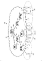
- FIG. 2 illustrates an embodiment 5G network architecture 200 comprising a wireless network domain 201 serving multiple radio access networks (RANs) 210, 220, 230.
- the wireless network domain 201 may include various gateway devices, e.g., packet data network (PDN) gateways, serving gateways (SGWs), while each of the RANs 210, 220, 230 may include one or more access points (APs), e.g., macro-base stations, low power nodes, etc.
- PDN packet data network
- SGWs serving gateways
- APs access points
- FIG. 3 illustrates an embodiment logical function architecture 300 for next-generation 5G wireless networks.
- the embodiment logical function architecture 300 comprises a management plane 310, a control plane 320, and a data plane 330.
- the management plane 310 may include entities for performing various management related tasks.
- the management plane 330 includes a data and analytics entity 311, an infrastructure management entity 312, customer service management entity 313, a connectivity management entity 314, and a content service management entity 315.
- the data and analytics entity 311 is configured to provide data analytics as a service (DAaaS). This may include manage on-demand network status analytics and on-demand service QoE status analytics for a particular service, and providing a data analytics summary to a client.
- the infrastructure management entity 312 may manage spectrum sharing between different radio access network (RANs) in a wireless network, or between wireless networks maintained by different operators. This may include wireless network integration, management of RAN backhaul and access link resources, coordination of spectrum sharing among co-located wireless networks, access management, air interface management, and device access naming and network node naming responsibilities.
- RANs radio access network
- the customer service management entity 313 may provide customer service functions, including managing customer context information, service-specific quality of experience (QoE) monitoring, and charging responsibilities.
- the connectivity management entity 314 may provide location tracking as a service (LTaaS) over the data plane of the wireless network.
- the connectivity management entity 314 may also have other responsibilities, such as establishing customized and scenario aware location tracking scheme, establishing software defined and virtual per-mobile user geographic location tracking schemes, and triggering user specific data plane topology updates.
- the content service management entity 315 may manage content caching in the wireless network. This may include selecting content to be cached in RAN, selecting caching locations, configuring cache capable network nodes, and managing content forwarding.
- the management plane may also include a security management entity that is responsible for network access security (e.g., service-specific security, customer device network access protection, etc.), as well as inter-domain and intra-domain wireless network security.
- the control plane 320 may include entities for performing various control related tasks.
- the control plane includes a software defined topology (SDT) logical entity 322, a software defined resource allocation (SDRA) logical entity 324, and a software defined per-service customized data plane process (SDP) logical entity 326.
- the SDT entity 322, the SDRA logical entity 324, and the SDP logical entity 326 may collectively configure a service-specific data plane for carrying service-related traffic.
- the software defined topology (SDT) logical entity 322 is configured to establish a virtual data-plane logical topology for a service. This may include selecting network devices to provide the service from a collection of network devices forming the data plane 330.
- the software defined resource allocation (SDRA) logical entity 324 is configured to map the virtual data-plane topology to a physical data-plane for transporting service-related traffic over the wireless network. This may include mapping logical links of the virtual data-plane topology to physical paths of the data plane.
- the software defined per-service customized data plane process (SDP) logical entity 326 is configured to select transport protocol(s) for transporting the service-related traffic over a physical data-plane of the wireless network. The transport protocols may be selected based on various criteria. In one example, the SDP logical entity selects the transport protocol based on a characteristic of the service-related traffic, e.g., business characteristic, payload volume, quality of service (QoS) requirement, etc. In another example, the SDP logical entity selects the transport protocol based on a condition on the network, e.g., loading on the data paths, etc.
- a characteristic of the service-related traffic e.g., business characteristic, payload volume, quality of service (Q
- the SDT entity 322, the SDRA logical entity 324, and the SDP logical entity 326 may have other responsibilities beyond their respective roles in establishing a service-specific data plane.
- the SDT entity 322 may dynamically define key functionality for v-s-SGWs/v-u-SGWs, as well as enable mobile VN migration and provide mobility management services.
- the SDRA logical entity 324 may embed virtual network sessions, as well as provide radio transmission coordination.
- One or both of the SDT entity 322 and the SDRA logical entity 324 may provide policy and charging rule function (PCRF) services.
- PCRF policy and charging rule function
- the SDT entity 322, the SDRA logical entity 324, and the SDP logical entity 326 may collectively configure a service-specific data plane for carrying service-related traffic.
- the SDT entity 322 establishes a virtual data-plane logical topology for the service
- the SDRA logical entity 324 maps the virtual data-plane topology to a physical data-plane path for transporting service-related traffic over the wireless network
- the SDP logical entity 326 select transport protocol(s) for transporting the service-related traffic over the physical data-plane.
- FIG. 4 illustrates a diagram 400 depicting a virtual data-plane logical topology 450 established for a service over the embodiment 5G network architecture illustrated in FIG. 2 .
- the virtual data-plane logical topology 450 includes a series of logical links 451, 542, 543 extending between network devices 411, 422, and 433 adapted to provide the service.
- a virtual service specific serving gateway (v-s-SGW) 401 is responsible for aggregating service-related traffic communicated between the network devices 411, 422, and 433.
- the SDP logical entity 326 may establish the virtual data-plane logical topology 450 by selecting the network devices 411, 422, and 433 to provide the service, as well as the v-s-SGW 401 for aggregating the service related traffic.
- FIG. 5 illustrates a diagram 500 depicting a physical data-plane 550 for transporting service-related traffic over the embodiment 5G network architecture illustrated in FIG. 2 .
- the physical data-plane 550 includes physical paths 511-513, 521-524, and 531-534 extending between the v-s-SGW 401 and the network nodes 411, 422, and 433 configured to provide the service.
- the physical paths 511-513 were mapped to the logical link 451
- the physical paths 521-524 were mapped to the logical link 542
- the physical paths 531-534 were mapped to the logical link 543.
- FIG. 6A illustrates an example 5G network architecture 600 that includes v-s-SGWs 612, 614 assigned to aggregate service-specific traffic. As shown, the v-s-SGWs 612, 614 are instantiated on a network device 610 . The v-s-SGWs 612, 614 are assigned to different services. Specifically, the v-s-SGWs 612 is assigned to a service being provided or accessed by the devices 622, and the v-s-SGWs 614 is assigned to a service being provided or accessed by the devices 644.
- v-s-SGWs 612, 614 are assigned different local v-s-SGW identifiers (IDs).
- IDs local v-s-SGW identifiers
- the v-s-SGW 612 is assigned a first local v-s-SGW ID (vID-1)
- vID-2 local v-s-SGW ID
- vID-2 second local v-s-SGW ID
- the local v-s-SGW IDs may be used, in combination with an ID assigned to the network device 610 (host ID-1), to communicate with the v-s-SGWs 612, 614.
- a packet e.g., data, control, management, or otherwise
- a packet specifying the host ID and the vID-1 may be routed to the v-s-SGW 612
- a packet specifying the host ID and the vID-2 may be routed to the v-s-SGW 614.
- FIG. 6B illustrates an example 5G network architecture 600 that includes v-u-SGWs 613, 615 assigned to UEs 633, 655 (respectively).
- the v-u-SGWs 613, 615 are instantiated on a network device 611, and are assigned different local v-u-SGW identifiers (IDs).
- IDs local v-u-SGW identifiers
- the v-u-SGW 613 is assigned a third local v-u-SGW ID (vID-3)
- the v-u-SGW 615 is assigned a fourth local v-u-SGW ID (vID-2).
- the local v-u-SGW IDs may be used, in combination with an ID assigned to the network device 611 (host ID 2), to communicate with the v-u-SGWs 613, 615.
- FIG. 7 illustrates an example 5G network architecture 700 for providing location tracking as a service (LTaaS).
- the example 5G network architecture 700 comprises network domains 701, 702, and an LTaaS layer 705.
- the network domain 701 includes a plurality of gateways 710, 715 and a plurality of APs 712, 714, 716, 718.
- the network domain 702 includes a plurality of gateways 720, 725 and a plurality of APs 724, 728.
- the gateways 710, 715, 720, 725 may include any network gateway e.g., virtual serving gateways (vSGWs) in a radio access network (RAN), SGWs or PGWs in an evolved packet core (EPC), etc.
- vSGWs virtual serving gateways
- the LTaaS layer 705 includes a central control center 750 and regional control centers 751, 752 positioned in the network domains 701, 702 (respectively).
- the LTaaS layer 705 may be completely centralized such that it only includes central control center 750, or completely distributed such that it only includes the regional control centers 751, 752.
- the LTaaS layer 705 may track the position of UEs 791, 792 as they migrate throughout the network domains 701, 702 by monitoring the relative locations of the UEs 791, 792 to network components (e.g., the gateways 710, 715, 720, 725, the APs 712, 714, 716, 718, 724, 728, etc.) in the network domains 701, 702.
- the granularity with which the LTaaS layer 705 monitors the position of the UEs 791, 792 may vary across different embodiments.
- the LTaaS layer 705 monitors the position of the UEs 791, 792 in relation to the APs 712, 714, 716, 718, 724, 728.
- the LTaaS layer 705 may be updated when a UE migrates from one AP to another, e.g., the UE 791 migrates from the AP 714 to the AP 712.
- the LTaaS layer 705 monitors the position of the UEs 791, 792 in relation to the gateways 710, 715, 720, 725.
- the LTaaS layer 705 may be updated when a UE migrates between APs associated with different gateways, but not when a UE migrates between APs associated with the same gateway.
- the LTaaS layer 705 may be updated when the UE 791 migrates from the AP 714 to the AP 716, as that would require re-associating the UE 791 with the gateway 715.
- no update may be triggered when the UE 791 migrates from the AP 714 to the AP 712, as those APs are both associated with the gateway 710.
- the LTaaS layer 705 monitors the position of the UEs 791, 792 in relation to the network domains 701, 702.
- the LTaaS layer 705 may be updated when a UE migrates between wireless network domains, but not when a UE migrates between different APs in the same network domain.
- the LTaaS layer 705 may be updated when the UE 792 migrates from the AP 728 to the AP 718, but not when the UE 792 migrates from the AP 728 to the AP 724.
- the regional datacenters 751 may track the location of the UEs 791, 792 with relation to a network device in the wireless network domains 701, 702, and the central datacenter 750 may track which wireless network domain the UEs 791, 792 are attached.
- the central datacenter 750 may store a carbon copy of the location tables maintained by the regional data centers 751, 752.
- FIG. 8 illustrates an example, 5G network architecture 800 adapted for content caching.
- the embodiment 5G network architecture 800 comprises network domains 801, 802, a wide area network (WAN) 803, and a content location tracking layer 805.
- the network domain 801 includes caching capable network devices 810, 811 a gateway 815, and a plurality of APs 812, 814, 816, 818.
- the network domain 802 includes a caching capable network device 820, a gateway 825, and a plurality of APs 824, 828.
- the network devices 810, 815, 820, 825 may include any network device, such as a gateway.
- Content stored in application servers 831, 832 may be pushed from the WAN 803 to the caching capable network devices 810, 811, 820 in the wireless network domains 801, 802 by content forwarding service managers (CFMs) instantiated on the regional control centers 851, 852 (respectively).
- CFMs content forwarding service managers
- the CFMs may sense the popularity of available content stored on the application servers 831, 832, and then prompt popular content to be pushed to one or more of the caching capable network devices 810, 811, 820.
- content may also be cached in one or more of the gateways 815, 825 or APs 812, 814, 816, 818.
- the caching capable network devices 810, 811, 820 may comprise virtual information-centric networking (ICN) servers of a ICN virtual network (VN), which may be transparent to the UEs 892, 894, 896, 898.
- the ICN VN may be operated by one of the wireless network operators or a third party.
- the caching capable network devices 810, 811, 820 may be adapted to provide cached content to a virtual user-specific serving gateway (v-u-SGW) of a served user equipment (UE) upon request.
- v-u-SGW virtual user-specific serving gateway
- the v-u-SGWs may be instantiated on the gateways 815, 825.
- the cached content may be stored by the caching capable network devices 810, 811, 820 in an information-centric networking (ICN) format, and the v-u-SGWs may translate the cached content from the ICN format to a user-specific format prior to sending it to one or more of the UEs 892, 894, 896, 898 that requested the content.
- the content forwarding service managers may update content cache tables in the regional control centers 851, 852 to indicate which network components in the wireless network domains 801, 802 are caching the content.
- a central control center 850 in the content location tracking layer 805 may store a central version of the content cache tables maintained at the regional control centers 851, 852.
- the content cache tables may associate a name of the content with a network address of the network device or the virtual IVN server included in the network device.
- An example system and method provide a 5G network referred to herein as MyNET, which is customized to consumers.
- MyNET includes network architecture and logical functionality architecture.
- An example architecture for a customized network provides for machine-to-machine (M2M) communication, private social networking, virtual network migration, security architecture, content in-radio access network (RAN), confederation network, customer location tracking as a service, network status analytics as a service, service delivery quality of experience (QoE) statistics as a service, device / mobile /user naming architecture, transport protocol, etc.
- M2M machine-to-machine
- RAN content in-radio access network
- QoE service delivery quality of experience
- the data plane of each MyNET network may be customized on a per-service basis.
- the RAN network has a service traffic aware data plane topology.
- Virtual service-specific serving gateways (v-s-SGWs) may be created on-demand, and dynamically configured based on machine distributions and traffic characteristics.
- Virtual mobile user-specific SGWs (v-u-SGW) and connectivity manager (v-u-CM) may be migrated to different network devices.
- Customized location tracking schemes are provided. Location tracking as a service is enabled.
- the v-u-SGWs' location and functionality are dynamically configured.
- the mobile's relative location (RL) is tracked.
- a virtual service-specific SGW may be independent from the public social network, and may provide service privacy.
- the v-s-SGW may be assigned to various services, such as video conferencing.
- the MyNET end-customer ad-hoc network may have a customer ad-hoc network-aware data plane architecture.
- the WN operator may configure one or more ad-hoc virtual cloud SGWs (v-c-SGWs) to forward/aggregate traffic of end-customers in the cloud to the ad-hoc cloud GWs.
- FIG. 13 illustrates example, MyNET support of content-centric network.
- Cache-in-RAN is controlled by content service (CS) control.
- Selective network nodes (NN) (CC-capable NN) are configured with store-and-forward and late binding functions.
- Content location is transparent to content consumers (v-u-SGW forwards interest/request to local CS controller or closest CC-node).
- the WNO communicates with content location resolution layer to get the content name-location info. WNO keeps the content name cache - CC-node address information in RAN.
- Example MyNET security architectures may provide multiple layer network access protection.
- Embodiment MyNET security architectures user/device specific and non-user specific wireless access protection.
- Preliminary WN access protection material is kept in all edge nodes, independent from customer device (WN-specific), and provides preliminary WN access protection.
- Secondary WN protection materials are kept in v-u-SGW, are user/device specific, and provide stronger WN access protection.
- the customer equipment obtains WN network access key materials to gain access.
- VN access materials are kept at edge GW of VN or v-u-SGW and provide VN-specific protection.
- Cooperative energy saving mode utilizes surrounding active devices/network to relay location update message and paging message.
- the VN may be active or idle.
- WN operators manage mobile MAC state and state transition, manage active VN and idle VN and transition, and manage customized access MAP. Corporation and collaboration of multiple geographically co-located and disjointed networks are developed by same or different operators.
- the device is independent from the operators.
- Device location tracking uses cooperation and control (customer LTaaS).
- WNO registers the location to global control center when a customer enters its WN and the corresponding GW address. WNO retrieves a WN name where a mobile customer currently is for data forwarding purposes. A global unique user/device name does not change during movement.
- the network access ID (PHYID/MACID) is local RAN-unique and is updated during movement. It is fully decoupled with internet protocol (IP).
- the naming structure For each device/UE/user (one user can have multiple devices), device naming registration (global) is done offline, and PHYID or network access ID is done on-line and is unique within a local area.
- the naming structure For v-u-SGW of each user/device, the naming structure includes the network address of the network node where the v-u-SGW locates, and a V-u-SGW ID (unique within the network node) are used.
- the naming structure includes intra-location RAN: NN ID (unique within a local RAN), and boundary node (Unique ID and global ID/IP address) are used.
- Flow ID is unique within a local RAN/core.
- Destination Node NA is unique within a local RAN/core.
- Sub-flow ID is unique within a device.
- FIG. 9 illustrates a block diagram of an embodiment of a communications device 900, which may be equivalent to one or more devices (e.g., UEs, NBs, etc.) discussed above.
- the communications device 900 may include a processor 904, a memory 906, and a plurality of interfaces 910, 912, 914, which may (or may not) be arranged as shown in FIG. 9 .
- the processor 904 may be any component capable of performing computations or other processing related tasks
- the memory 906 may be any component capable of storing programming or instructions for the processor 904.
- the interfaces 910 may be any component or collection of components that allows the communications device 900 to communicate with other devices.
- FIG. 10 is a block diagram of a processing system that may be used for implementing the devices and methods disclosed herein. Specific devices may utilize all of the components shown, or only a subset of the components, and levels of integration may vary from device to device. Furthermore, a device may contain multiple instances of a component, such as multiple processing units, processors, memories, transmitters, receivers, etc.
- the processing system may comprise a processing unit equipped with one or more input/output devices, such as a speaker, microphone, mouse, touchscreen, keypad, keyboard, printer, display, and the like.
- the processing unit may include a central processing unit (CPU), memory, a mass storage device, a video adapter, and an I/O interface connected to a bus.
- CPU central processing unit
- the bus may be one or more of any type of several bus architectures including a memory bus or memory controller, a peripheral bus, video bus, or the like.
- the CPU may comprise any type of electronic data processor.
- the memory may comprise any type of non-transitory system memory such as static random access memory (SRAM), dynamic random access memory (DRAM), synchronous DRAM (SDRAM), read-only memory (ROM), a combination thereof, or the like.
- SRAM static random access memory
- DRAM dynamic random access memory
- SDRAM synchronous DRAM
- ROM read-only memory
- the memory may include ROM for use at boot-up, and DRAM for program and data storage for use while executing programs.
- the mass storage device may comprise any type of non-transitory storage device configured to store data, programs, and other information and to make the data, programs, and other information accessible via the bus.
- the mass storage device may comprise, for example, one or more of a solid state drive, hard disk drive, a magnetic disk drive, an optical disk drive, or the like.
- the video adapter and the I/O interface provide interfaces to couple external input and output devices to the processing unit.
- input and output devices include the display coupled to the video adapter and the mouse/keyboard/printer coupled to the I/O interface.
- Other devices may be coupled to the processing unit, and additional or fewer interface cards may be utilized.
- a serial interface such as Universal Serial Bus (USB) (not shown) may be used to provide an interface for a printer.
- USB Universal Serial Bus
- the processing unit also includes one or more network interfaces, which may comprise wired links, such as an Ethernet cable or the like, or wireless links to access nodes or different networks.
- the network interface allows the processing unit to communicate with remote units via the networks.
- the network interface may provide wireless communication via one or more transmitters/transmit antennas and one or more receivers/receive antennas.
- the processing unit is coupled to a local-area network or a wide-area network for data processing and communications with remote devices, such as other processing units, the Internet, remote storage facilities, or the like.
- a method for routing traffic comprising:
- the local ID is assigned to the v-u-SGW by the network device.
- a method for providing network services comprising:
- the v-s-SGW provides access protection for the service-related traffic communicated over bearer channels extending between the v-s-SGW and wirelessly-enabled devices in the group of wirelessly-enabled devices.
- the v-s-SGW provides a layer two (L2) anchor point between the group of wirelessly-enabled devices.
- least some wirelessly-enabled devices in the group of wirelessly-enabled devices utilize different wireless communication protocols than one another, and wherein the v-s-SGW provides a layer two (L2) anchor point for convergence between the different wireless communication protocols.
- At least some wirelessly-enabled devices in the group of wirelessly-enabled devices are positioned in different radio access networks (RANs), and wherein the v-s-SGW provides a layer two (L2) anchor point for multi-RAN convergence between the different RANs.
- the v-s-SGW performs at least some application layer processing for the service related traffic.
- the v-s-SGW computes at least some statistical information corresponding to the service related traffic, and communicates the statistical information in control messages to UEs in the group of UEs, application servers in the one or more application servers, or combinations thereof.
- the application layer processing performed by the v-s-SGW is configured by a client.
- the application layer processing performed by the v-s-SGW is configured by an operator.
- a method for location tracking comprising:
- the LTaaS layer is operated by at least one operator of the wireless networks. In a further embodiment, the LTaaS layer is operated by a third party that is different than operator(s) of the wireless networks. In another embodiment, the LTaaS layer comprises a central control center that is independent from the wireless networks. In another aspect, the first network device comprises an access point in the first wireless network. In another aspect, the first network device comprises a serving gateway (SGW) in the first wireless network.
- SGW serving gateway
- the first UE is in a second wireless network that is separate from the first wireless network, and wherein the method further comprises sending an update from the central control center in the LTaaS layer to a regional control center in the second wireless network, the update indicating that the first UE is located nearby the first network device in the first wireless network, wherein the regional control center in the second wireless network is adapted to notify the second UE of a relative location of the first UE upon request.
- the second wireless network is operated by a different network operator than the first wireless network.
- the LTaaS layer comprises distributed regional controllers located in the wireless networks.
- a first one of the UEs is positioned in a first wireless network
- tracking the locations of the UEs via the LTaaS layer comprises: determining that the first UE has migrated to a position nearby a first network device in the first wireless network; and updating a first regional control center in the first wireless network to indicate that the first UE is located nearby the first network device in the first wireless network.
- a second one of the UEs is positioned in a second wireless network that is separate from the first wireless network, and wherein the method further comprises: sending an update from the first regional control center to a second regional control center in the second wireless network, the update indicating that the first UE is located nearby the first network device in the first wireless network, wherein the regional control center in the second wireless network is adapted to notify the second UE of a relative location of the first UE upon request.
- the method further comprises:
- the third party operator operates a network resource over which traffic destined for the first UE is being transported.
- the third party operator is a virtual operator.
- method for content caching comprises:
- the selected content is stored by the network device in an information-centric networking (ICN) format.
- the v-u-SGW is adapted to translate the selected content from the ICN format to a user-specific format before relaying the content having the user-specific format to the served UE.
- the user-specific format comprises an internet protocol (IP) format.
- the method further comprises updating a content cache table stored in the CFM to indicate that the selected content has been cached by the network device.
- the content cache table associates a name of the content with a network address of the virtual IVN server.
- the ICN VN is transparent to the served UE.
- the ICN VN is operated by an operator of the wireless network.
- the ICN VN is operated by a third party operator that is different than an operator of the wireless network.
- a method for content caching comprising:
- a method for execution at a resource allocation logical entity comprising:
Landscapes
- Engineering & Computer Science (AREA)
- Computer Networks & Wireless Communication (AREA)
- Signal Processing (AREA)
- Business, Economics & Management (AREA)
- Accounting & Taxation (AREA)
- Physics & Mathematics (AREA)
- Probability & Statistics with Applications (AREA)
- Mobile Radio Communication Systems (AREA)
- Data Exchanges In Wide-Area Networks (AREA)
Claims (11)
- Verfahren, umfassend:Herstellen, durch eine logische Entität für eine softwaredefinierte Topologie, SDT, (322) einer logischen virtuellen Datenebenentopologie für einen Dienst, wobei die logische virtuelle Datenebenentopologie für den Dienst spezifisch ist;Abbilden, durch eine logische Entität für eine softwaredefinierte Ressourcenzuweisung, SDRA, (324) der für den Dienst spezifischen virtuellen Datenebenentopologie auf eine physische Datenebene zum Transportieren dienstbezogenen Verkehrs über ein drahtloses Netz; undAuswählen, durch eine logische Entität für einen softwaredefinierten prodienst-zugeschnittenen Datenebenenprozess, SDP, (326) von einem Transportprotokoll bzw. von Transportprotokollen zum Transportieren des dienstbezogenen Verkehrs über eine physische Datenebene des drahtlosen Netzes.
- Verfahren nach Anspruch 1, wobei Herstellen der virtuellen Datenebenentopologie Folgendes umfasst:
Auswählen von Netzvorrichtungen zum Bereitstellen des Dienstes aus einer Sammlung von Netzvorrichtungen, die die physische Datenebene ausbilden. - Verfahren nach Anspruch 2, wobei Abbilden der virtuellen Datenebenentopologie auf die physische Datenebene Abbilden logischer Verbindungen der virtuellen Datenebenentopologie auf physische Wege der physischen Datenebene umfasst, wobei sich die logischen Verbindungen zwischen den zum Bereitstellen des Dienstes ausgewählten Netzvorrichtungen erstrecken.
- Verfahren nach Anspruch 3, wobei Auswählen des Transportprotokolls bzw. der Transportprotokolle zum Transportieren des dienstbezogenen Verkehrs über die physische Datenebene Folgendes umfasst:
Auswählen des Transportprotokolls bzw. der Transportprotokolle gemäß einer Eigenschaft des dienstbezogenen Verkehrs. - Verfahren nach einem der Ansprüche 1 bis 4, ferner umfassend:
Managen, durch eine Infrastrukturmanagemententität, von Spektrumgemeinnutzens zwischen verschiedenen Funkzugangsnetzen (RANs) in dem drahtlosen Netz. - Verfahren nach Anspruch 5, ferner umfassend:
Managen, durch die Infrastrukturmanagemententität, von Spektrumgemeinnutzens zwischen mehreren drahtlosen Netzen. - Verfahren nach einem der Ansprüche 5 und 6, ferner umfassend:
Bereitstellen, durch eine Daten- und Analyseentität, von Datenanalyse als einen Dienst. - Verfahren nach einem der Ansprüche 5 bis 7, ferner umfassend:
Belasten, durch eine Kundendienstmanagemententität, von Clients für Nutzung der Datenebene gemäß einer Dienstvereinbarung. - Verfahren nach einem der Ansprüche 5 bis 8, ferner umfassend:
Bereitstellen, durch eine Konnektivitätsmanagemententität, von Standortverfolgung als einen Dienst (LTaaS) über die Datenebene des drahtlosen Netzes. - Verfahren nach einem der Ansprüche 5 bis 9, ferner umfassend:
Managen, durch eine Inhaltsdienstmanagemententität, von Inhaltscachen auf der Datenebene des drahtlosen Netzes. - Steuerungsebene für ein drahtloses Netz (320), umfassend:eine Vielzahl von Prozessoren (904);eine Vielzahl von computerlesbaren Speichern (906), die Anweisungen speichern, die, wenn sie durch Prozessoren aus der Vielzahl von Prozessoren (904) ausgeführt werden, die sie Steuerungsebene für ein drahtloses Netz (320) zu veranlassen, zum Instanziieren:einer logischen Entität für eine softwaredefinierte Topologie, SDT, (322) zum Definieren einer logischen virtuellen Datenebenentopologie für einen Dienst, wobei die logische virtuelle Datenebenentopologie für den Dienst spezifisch ist;einer logischen Entität für eine softwaredefinierte Ressourcenzuweisung, SDRA, (324) zum Abbilden der für den Dienst spezifischen virtuellen Datenebenentopologie auf eine physische Datenebene zum Transportieren dienstbezogenen Verkehrs über ein drahtloses Netz; undeiner logischen Entität für einen softwaredefinierten prodienst-zugeschnittenen Datenebenenprozess, SDP, (326) zum Auswählen von mindestens einem Transportprotokoll zum Transportieren des dienstbezogenen Verkehrs über eine physische Datenebene des drahtlosen Netzes.
Priority Applications (1)
| Application Number | Priority Date | Filing Date | Title |
|---|---|---|---|
| EP18179993.3A EP3425848B1 (de) | 2014-03-05 | 2015-03-05 | System und methode für ein angepasstes netzwerk der fünften generation (5g) |
Applications Claiming Priority (3)
| Application Number | Priority Date | Filing Date | Title |
|---|---|---|---|
| US201461948507P | 2014-03-05 | 2014-03-05 | |
| US201461994626P | 2014-05-16 | 2014-05-16 | |
| PCT/US2015/018970 WO2015134751A1 (en) | 2014-03-05 | 2015-03-05 | System and method for a customized fifth generation (5g) network |
Related Child Applications (2)
| Application Number | Title | Priority Date | Filing Date |
|---|---|---|---|
| EP18179993.3A Division EP3425848B1 (de) | 2014-03-05 | 2015-03-05 | System und methode für ein angepasstes netzwerk der fünften generation (5g) |
| EP18179993.3A Division-Into EP3425848B1 (de) | 2014-03-05 | 2015-03-05 | System und methode für ein angepasstes netzwerk der fünften generation (5g) |
Publications (3)
| Publication Number | Publication Date |
|---|---|
| EP3105946A1 EP3105946A1 (de) | 2016-12-21 |
| EP3105946A4 EP3105946A4 (de) | 2017-07-12 |
| EP3105946B1 true EP3105946B1 (de) | 2018-09-19 |
Family
ID=54018787
Family Applications (2)
| Application Number | Title | Priority Date | Filing Date |
|---|---|---|---|
| EP15758835.1A Active EP3105946B1 (de) | 2014-03-05 | 2015-03-05 | System und verfahren ein individualisiertes netzwerk der fünften generation (5g) |
| EP18179993.3A Active EP3425848B1 (de) | 2014-03-05 | 2015-03-05 | System und methode für ein angepasstes netzwerk der fünften generation (5g) |
Family Applications After (1)
| Application Number | Title | Priority Date | Filing Date |
|---|---|---|---|
| EP18179993.3A Active EP3425848B1 (de) | 2014-03-05 | 2015-03-05 | System und methode für ein angepasstes netzwerk der fünften generation (5g) |
Country Status (6)
| Country | Link |
|---|---|
| US (2) | US9788211B2 (de) |
| EP (2) | EP3105946B1 (de) |
| JP (2) | JP6363723B2 (de) |
| KR (2) | KR102048333B1 (de) |
| CN (2) | CN110611899B (de) |
| WO (1) | WO2015134751A1 (de) |
Families Citing this family (70)
| Publication number | Priority date | Publication date | Assignee | Title |
|---|---|---|---|---|
| WO2015144226A1 (en) * | 2014-03-27 | 2015-10-01 | Nokia Solutions And Networks Oy | On demand network service in 5th generation mobile networks |
| US10084643B2 (en) | 2014-11-28 | 2018-09-25 | Huawei Technologies Co., Ltd. | Systems and methods for providing customized virtual wireless networks based on service oriented network auto-creation |
| US9775045B2 (en) | 2015-09-11 | 2017-09-26 | Intel IP Corporation | Slicing architecture for wireless communication |
| DE112016004103T5 (de) * | 2015-09-11 | 2018-05-30 | Intel IP Corporation | Slice-fähige Funkzugangsnetzwerkarchitektur zur Drahtloskommunikation |
| WO2017074486A1 (en) * | 2015-10-28 | 2017-05-04 | Intel IP Corporation | Slice-based operation in wireless networks with end-to-end network slicing |
| US10129108B2 (en) * | 2015-11-13 | 2018-11-13 | Huawei Technologies Co., Ltd. | System and methods for network management and orchestration for network slicing |
| SI3398378T1 (sl) * | 2015-12-30 | 2021-04-30 | Deutsche Telekom Ag | Postopek za vzpostavitev zveze med gostovanjem |
| WO2017148542A1 (en) * | 2016-03-01 | 2017-09-08 | Telefonaktiebolaget Lm Ericsson (Publ) | Handover initiated alignment of pending interest tables |
| CN108886703B (zh) | 2016-04-04 | 2022-06-10 | 诺基亚技术有限公司 | 在5g系统中的情境感知qos/qoe策略供应和适配 |
| PL3443713T3 (pl) | 2016-04-11 | 2020-07-13 | Nokia Technologies Oy | Egzekwowanie zarządzania przepływami QoS/QoE w sieci 5G |
| US10149193B2 (en) | 2016-06-15 | 2018-12-04 | At&T Intellectual Property I, L.P. | Method and apparatus for dynamically managing network resources |
| US10841208B2 (en) | 2016-08-05 | 2020-11-17 | Huawei Technologies Co., Ltd. | Slice/service-based routing in virtual networks |
| WO2018034156A1 (ja) * | 2016-08-17 | 2018-02-22 | 株式会社Nttドコモ | スライス割当方法 |
| CN109565469A (zh) * | 2016-08-17 | 2019-04-02 | 株式会社Ntt都科摩 | 切片分配方法 |
| GB2553558B (en) * | 2016-09-08 | 2019-02-20 | Ip Access Ltd | Network entities, a wireless communication system and a method for collecting data for multiple mobile network operators |
| US10284730B2 (en) | 2016-11-01 | 2019-05-07 | At&T Intellectual Property I, L.P. | Method and apparatus for adaptive charging and performance in a software defined network |
| US10454836B2 (en) | 2016-11-01 | 2019-10-22 | At&T Intellectual Property I, L.P. | Method and apparatus for dynamically adapting a software defined network |
| US20180123896A1 (en) * | 2016-11-01 | 2018-05-03 | Huawei Technologies Co., Ltd. | Systems and methods for hierarchical network management |
| US10505870B2 (en) | 2016-11-07 | 2019-12-10 | At&T Intellectual Property I, L.P. | Method and apparatus for a responsive software defined network |
| US10469376B2 (en) | 2016-11-15 | 2019-11-05 | At&T Intellectual Property I, L.P. | Method and apparatus for dynamic network routing in a software defined network |
| US10039006B2 (en) | 2016-12-05 | 2018-07-31 | At&T Intellectual Property I, L.P. | Method and system providing local data breakout within mobility networks |
| US10536981B2 (en) | 2017-01-05 | 2020-01-14 | At&T Intellectual Property I, L.P. | Long-term evolution assisted new radio initial access and mobility for 5G or other next generation networks |
| US10264075B2 (en) * | 2017-02-27 | 2019-04-16 | At&T Intellectual Property I, L.P. | Methods, systems, and devices for multiplexing service information from sensor data |
| US10469286B2 (en) | 2017-03-06 | 2019-11-05 | At&T Intellectual Property I, L.P. | Methods, systems, and devices for managing client devices using a virtual anchor manager |
| US10841184B2 (en) * | 2017-03-28 | 2020-11-17 | Huawei Technologies Co., Ltd. | Architecture for integrating service, network and domain management subsystems |
| CN107257583B (zh) * | 2017-04-26 | 2020-09-01 | 重庆邮电大学 | 一种基于自回传小蜂窝网络的虚拟资源分配方法 |
| US10749796B2 (en) | 2017-04-27 | 2020-08-18 | At&T Intellectual Property I, L.P. | Method and apparatus for selecting processing paths in a software defined network |
| US10212289B2 (en) | 2017-04-27 | 2019-02-19 | At&T Intellectual Property I, L.P. | Method and apparatus for managing resources in a software defined network |
| US10673751B2 (en) | 2017-04-27 | 2020-06-02 | At&T Intellectual Property I, L.P. | Method and apparatus for enhancing services in a software defined network |
| US10819606B2 (en) | 2017-04-27 | 2020-10-27 | At&T Intellectual Property I, L.P. | Method and apparatus for selecting processing paths in a converged network |
| US10257668B2 (en) | 2017-05-09 | 2019-04-09 | At&T Intellectual Property I, L.P. | Dynamic network slice-switching and handover system and method |
| US10382903B2 (en) | 2017-05-09 | 2019-08-13 | At&T Intellectual Property I, L.P. | Multi-slicing orchestration system and method for service and/or content delivery |
| US10630552B2 (en) * | 2017-06-08 | 2020-04-21 | Huawei Technologies Co., Ltd. | Wireless communication access node (WCAN) device based policy enforcement and statistics collection in anchorless communication systems |
| US10834575B2 (en) | 2017-06-16 | 2020-11-10 | At&T Intellectual Property I, L.P. | Initial access configuration for coexistence of multiple wireless communication systems |
| WO2018236624A1 (en) * | 2017-06-19 | 2018-12-27 | Intel IP Corporation | Devices and methods for ue-specific ran-cn associations |
| US10070344B1 (en) | 2017-07-25 | 2018-09-04 | At&T Intellectual Property I, L.P. | Method and system for managing utilization of slices in a virtual network function environment |
| US11823273B2 (en) | 2017-10-06 | 2023-11-21 | BlueOwl, LLC | System and method for preventing fraud in the capture of trip telemetry data |
| KR101985266B1 (ko) * | 2017-10-18 | 2019-06-03 | 에스케이 텔레콤주식회사 | 패킷 처리 기능 선택방법 및 그를 위한 장치 |
| US10104548B1 (en) | 2017-12-18 | 2018-10-16 | At&T Intellectual Property I, L.P. | Method and apparatus for dynamic instantiation of virtual service slices for autonomous machines |
| WO2019210437A1 (en) * | 2018-04-30 | 2019-11-07 | Qualcomm Incorporated | An addressing model and method |
| US11039315B2 (en) | 2018-08-01 | 2021-06-15 | At&T Intellectual Property I, L.P. | On-demand super slice instantiation and orchestration |
| GB2577055B (en) | 2018-09-11 | 2021-09-01 | Samsung Electronics Co Ltd | Improvements in and relating to telecommunication networks |
| CN112789882A (zh) * | 2018-10-01 | 2021-05-11 | 康普技术有限责任公司 | 集中式无线电接入网络中的控制器冗余 |
| US11930471B2 (en) | 2018-11-02 | 2024-03-12 | Apple Inc. | Supporting information centric networking in next generation cellular networks |
| US10925105B2 (en) | 2018-12-12 | 2021-02-16 | Bank Of America Corporation | Hybrid system local area network |
| US11013043B2 (en) * | 2019-01-08 | 2021-05-18 | Micron Technology, Inc. | Methods and apparatus for routine based fog networking |
| KR102704801B1 (ko) | 2019-02-19 | 2024-09-09 | 삼성전자주식회사 | 안테나 구조체의 신호 방사를 지원하는 전자 장치 |
| US10461421B1 (en) | 2019-05-07 | 2019-10-29 | Bao Tran | Cellular system |
| US10498029B1 (en) | 2019-07-15 | 2019-12-03 | Bao Tran | Cellular system |
| US11321282B2 (en) | 2019-05-17 | 2022-05-03 | Bao Tran | Blockchain cellular system |
| US12289083B2 (en) | 2019-05-31 | 2025-04-29 | Semiconductor Energy Laboratory Co., Ltd. | Communication device |
| US11017017B2 (en) * | 2019-06-04 | 2021-05-25 | International Business Machines Corporation | Real-time vision assistance |
| GB2586328B (en) * | 2019-06-11 | 2022-04-27 | Samsung Electronics Co Ltd | Improvements in and relating to the provision of data analytics in a telecommunication network |
| CN110381020B (zh) * | 2019-06-13 | 2021-10-29 | 长沙理工大学 | 一种ids资源配置方法、装置和计算机可读存储介质 |
| US10735936B1 (en) | 2019-06-19 | 2020-08-04 | Bank Of America Corporation | Leveraging fifth generation (5G) cellular capabilities for transmission and reception of emergency notifications and responses |
| US11523276B2 (en) | 2019-06-28 | 2022-12-06 | Bank Of America Corporation | Utilizing a high generation cellular network to authorize an event |
| US11301900B2 (en) | 2019-07-01 | 2022-04-12 | Bank Of America Corporation | Real-time multi-computer data exchange and control system |
| US11418503B2 (en) | 2019-07-03 | 2022-08-16 | Bank Of America Corporation | Sensor-based authentication, notification, and assistance systems |
| US11017773B2 (en) | 2019-07-09 | 2021-05-25 | Bank Of America Corporation | Voice-based time-sensitive task processing over a high generation cellular network |
| US11317280B2 (en) | 2019-07-24 | 2022-04-26 | Bank Of America Corporation | Real-time authentication using a mobile device on a high generation cellular network |
| US10706704B1 (en) | 2019-07-25 | 2020-07-07 | Bank Of America Corporation | Utilizing a high generation cellular network for identifying devices associated with unauthorized activities and notifying enterprise facilities |
| US11337144B2 (en) | 2019-08-06 | 2022-05-17 | Bank Of America Corporation | Multicomputer signal processing to dynamically generate customized output and control functions |
| US11330006B2 (en) | 2019-08-29 | 2022-05-10 | Bank Of America Corporation | Detecting and identifying devices at enterprise locations to protect enterprise-managed information and resources |
| US11356462B2 (en) | 2019-08-29 | 2022-06-07 | Bank Of America Corporation | Detecting and identifying devices at enterprise locations to protect enterprise-managed information and resources |
| US10694399B1 (en) | 2019-09-02 | 2020-06-23 | Bao Tran | Cellular system |
| US10812992B1 (en) | 2019-09-02 | 2020-10-20 | Bao Tran | Cellular system |
| KR102798665B1 (ko) | 2019-11-07 | 2025-04-18 | 후아웨이 테크놀러지 컴퍼니 리미티드 | 애널리틱스 생성을 지원하기 위한 네트워크 엔티티 |
| WO2021166249A1 (ja) * | 2020-02-21 | 2021-08-26 | 日本電信電話株式会社 | 通信装置、通信方法及びプログラム |
| US11381972B2 (en) | 2020-02-24 | 2022-07-05 | Bank Of America Corporation | Optimizing authentication and management of wireless devices in zero trust computing environments |
| EP4309346A4 (de) | 2021-06-28 | 2024-10-02 | Samsung Electronics Co., Ltd. | Verfahren und system zur verbesserung der cache-verwaltung in einer 5g-netzwerkfunktion |
Family Cites Families (21)
| Publication number | Priority date | Publication date | Assignee | Title |
|---|---|---|---|---|
| US7804826B1 (en) * | 2002-11-15 | 2010-09-28 | Nortel Networks Limited | Mobile IP over VPN communication protocol |
| US7802251B2 (en) * | 2005-11-09 | 2010-09-21 | Hitachi, Ltd. | System for resource allocation to an active virtual machine using switch and controller to associate resource groups |
| US8391873B2 (en) | 2006-07-21 | 2013-03-05 | Qualcomm Incorporated | Systems and methods for coordinating supplementary services for voice telephone calls in a centralized fashion |
| US7822594B2 (en) | 2006-08-07 | 2010-10-26 | Voltaire Ltd. | Service-oriented infrastructure management |
| US8032939B2 (en) | 2007-11-06 | 2011-10-04 | Airtight Networks, Inc. | Method and system for providing wireless vulnerability management for local area computer networks |
| GB2457432A (en) * | 2008-01-28 | 2009-08-19 | Fujitsu Lab Of Europ Ltd | Mitigating interference in wireless communication systems |
| US8958339B2 (en) * | 2009-05-22 | 2015-02-17 | Nec Europe Ltd. | Method for supporting routing decisions in a wireless mesh network and wireless mesh network |
| US9416690B2 (en) * | 2009-07-30 | 2016-08-16 | Freudenberg-Nok General Partnership | Reduced inertia valve stem seal flange |
| KR101277274B1 (ko) * | 2009-11-27 | 2013-06-20 | 한국전자통신연구원 | 자원 간의 물리적/논리적 관계를 맵핑하는 방법 및 장치 |
| CN104935669B (zh) * | 2010-03-09 | 2020-02-14 | Iot控股公司 | 一种机器对机器(m2m)通信的方法及网关 |
| JP5190084B2 (ja) * | 2010-03-30 | 2013-04-24 | 株式会社日立製作所 | 仮想マシンのマイグレーション方法およびシステム |
| US8909786B2 (en) | 2010-08-26 | 2014-12-09 | Futurewei Technologies, Inc. | Method and system for cross-stratum optimization in application-transport networks |
| WO2011144067A2 (zh) | 2011-05-24 | 2011-11-24 | 华为技术有限公司 | 处理报文的方法和装置 |
| TWI474681B (zh) | 2012-05-11 | 2015-02-21 | Hope Bay Technologies Inc | 雲端系統中的虛擬機器連線方法 |
| US9160183B2 (en) * | 2012-06-27 | 2015-10-13 | Bren-Tronics, Inc. | Foldable battery charger |
| US20140020102A1 (en) * | 2012-07-16 | 2014-01-16 | Infosys Limited | Integrated network architecture |
| CN102801715B (zh) * | 2012-07-30 | 2015-03-11 | 华为技术有限公司 | 一种网络中虚拟机迁移的方法、网关及系统 |
| CN102904794A (zh) * | 2012-09-27 | 2013-01-30 | 北京邮电大学 | 一种虚拟网络映射方法和装置 |
| CN103051629B (zh) * | 2012-12-24 | 2017-02-08 | 华为技术有限公司 | 一种基于软件定义网络中数据处理的系统、方法和节点 |
| US10291515B2 (en) * | 2013-04-10 | 2019-05-14 | Huawei Technologies Co., Ltd. | System and method for a control plane reference model framework |
| US10034222B2 (en) * | 2013-06-06 | 2018-07-24 | Huawei Technologies Co., Ltd. | System and method for mapping a service-level topology to a service-specific data plane logical topology |
-
2015
- 2015-03-05 EP EP15758835.1A patent/EP3105946B1/de active Active
- 2015-03-05 KR KR1020187020988A patent/KR102048333B1/ko active Active
- 2015-03-05 WO PCT/US2015/018970 patent/WO2015134751A1/en not_active Ceased
- 2015-03-05 JP JP2016555510A patent/JP6363723B2/ja active Active
- 2015-03-05 US US14/639,572 patent/US9788211B2/en active Active
- 2015-03-05 CN CN201910614862.6A patent/CN110611899B/zh active Active
- 2015-03-05 KR KR1020167027575A patent/KR101882884B1/ko active Active
- 2015-03-05 EP EP18179993.3A patent/EP3425848B1/de active Active
- 2015-03-05 CN CN201580011201.4A patent/CN106063298B/zh active Active
-
2017
- 2017-09-12 US US15/702,428 patent/US10484877B2/en active Active
-
2018
- 2018-06-28 JP JP2018123457A patent/JP6612935B2/ja active Active
Non-Patent Citations (1)
| Title |
|---|
| None * |
Also Published As
| Publication number | Publication date |
|---|---|
| EP3105946A1 (de) | 2016-12-21 |
| JP2018148589A (ja) | 2018-09-20 |
| EP3425848B1 (de) | 2021-08-11 |
| CN110611899B (zh) | 2022-02-15 |
| JP6363723B2 (ja) | 2018-07-25 |
| JP6612935B2 (ja) | 2019-11-27 |
| US20150257012A1 (en) | 2015-09-10 |
| US9788211B2 (en) | 2017-10-10 |
| KR102048333B1 (ko) | 2019-11-25 |
| WO2015134751A1 (en) | 2015-09-11 |
| JP2017518653A (ja) | 2017-07-06 |
| CN106063298B (zh) | 2019-07-12 |
| CN110611899A (zh) | 2019-12-24 |
| KR20180087454A (ko) | 2018-08-01 |
| KR20160129896A (ko) | 2016-11-09 |
| US20180014204A1 (en) | 2018-01-11 |
| US10484877B2 (en) | 2019-11-19 |
| EP3105946A4 (de) | 2017-07-12 |
| CN106063298A (zh) | 2016-10-26 |
| KR101882884B1 (ko) | 2018-07-27 |
| EP3425848A1 (de) | 2019-01-09 |
Similar Documents
| Publication | Publication Date | Title |
|---|---|---|
| US10484877B2 (en) | System and method for a customized fifth generation (5G) network | |
| US11711858B2 (en) | Shared PDU session establishment and binding | |
| EP3494677B1 (de) | Slice-/dienstbasiertes routing in virtuellen netzwerken | |
| CN112153098B (zh) | 一种应用迁移方法及装置 | |
| US9775008B2 (en) | System and method for elastic scaling in a push to talk (PTT) platform using user affinity groups | |
| JP6463839B2 (ja) | モバイル環境におけるフローベースのアドレス指定のためのシステム及び方法 | |
| US9924483B2 (en) | Systems and methods for signal brokering in distributed evolved packet core (EPC) network architectures | |
| US12376017B2 (en) | Methods and apparatus for transport context translation | |
| US20260075028A1 (en) | Automatic detection and failover of multimedia message service center (mmsc) servers from user plane function voice (upfv) in public cloud services | |
| US12323304B2 (en) | Method to update 5G VN group topology update to AF for efficient network management |
Legal Events
| Date | Code | Title | Description |
|---|---|---|---|
| STAA | Information on the status of an ep patent application or granted ep patent |
Free format text: STATUS: THE INTERNATIONAL PUBLICATION HAS BEEN MADE |
|
| PUAI | Public reference made under article 153(3) epc to a published international application that has entered the european phase |
Free format text: ORIGINAL CODE: 0009012 |
|
| STAA | Information on the status of an ep patent application or granted ep patent |
Free format text: STATUS: REQUEST FOR EXAMINATION WAS MADE |
|
| 17P | Request for examination filed |
Effective date: 20160915 |
|
| AK | Designated contracting states |
Kind code of ref document: A1 Designated state(s): AL AT BE BG CH CY CZ DE DK EE ES FI FR GB GR HR HU IE IS IT LI LT LU LV MC MK MT NL NO PL PT RO RS SE SI SK SM TR |
|
| AX | Request for extension of the european patent |
Extension state: BA ME |
|
| DAV | Request for validation of the european patent (deleted) | ||
| DAX | Request for extension of the european patent (deleted) | ||
| A4 | Supplementary search report drawn up and despatched |
Effective date: 20170612 |
|
| RIC1 | Information provided on ipc code assigned before grant |
Ipc: H04W 4/00 20090101AFI20170606BHEP |
|
| REG | Reference to a national code |
Ref country code: DE Ref legal event code: R079 Ref document number: 602015016687 Country of ref document: DE Free format text: PREVIOUS MAIN CLASS: H04W0004000000 Ipc: H04M0015000000 |
|
| GRAP | Despatch of communication of intention to grant a patent |
Free format text: ORIGINAL CODE: EPIDOSNIGR1 |
|
| STAA | Information on the status of an ep patent application or granted ep patent |
Free format text: STATUS: GRANT OF PATENT IS INTENDED |
|
| RIC1 | Information provided on ipc code assigned before grant |
Ipc: H04M 15/00 20060101AFI20180228BHEP Ipc: H04L 12/14 20060101ALI20180228BHEP Ipc: H04W 4/24 20090101ALI20180228BHEP |
|
| INTG | Intention to grant announced |
Effective date: 20180404 |
|
| GRAS | Grant fee paid |
Free format text: ORIGINAL CODE: EPIDOSNIGR3 |
|
| GRAA | (expected) grant |
Free format text: ORIGINAL CODE: 0009210 |
|
| STAA | Information on the status of an ep patent application or granted ep patent |
Free format text: STATUS: THE PATENT HAS BEEN GRANTED |
|
| AK | Designated contracting states |
Kind code of ref document: B1 Designated state(s): AL AT BE BG CH CY CZ DE DK EE ES FI FR GB GR HR HU IE IS IT LI LT LU LV MC MK MT NL NO PL PT RO RS SE SI SK SM TR |
|
| REG | Reference to a national code |
Ref country code: GB Ref legal event code: FG4D |
|
| REG | Reference to a national code |
Ref country code: CH Ref legal event code: EP |
|
| REG | Reference to a national code |
Ref country code: AT Ref legal event code: REF Ref document number: 1044647 Country of ref document: AT Kind code of ref document: T Effective date: 20181015 |
|
| REG | Reference to a national code |
Ref country code: IE Ref legal event code: FG4D |
|
| REG | Reference to a national code |
Ref country code: DE Ref legal event code: R096 Ref document number: 602015016687 Country of ref document: DE |
|
| REG | Reference to a national code |
Ref country code: NL Ref legal event code: MP Effective date: 20180919 |
|
| PG25 | Lapsed in a contracting state [announced via postgrant information from national office to epo] |
Ref country code: SE Free format text: LAPSE BECAUSE OF FAILURE TO SUBMIT A TRANSLATION OF THE DESCRIPTION OR TO PAY THE FEE WITHIN THE PRESCRIBED TIME-LIMIT Effective date: 20180919 Ref country code: BG Free format text: LAPSE BECAUSE OF FAILURE TO SUBMIT A TRANSLATION OF THE DESCRIPTION OR TO PAY THE FEE WITHIN THE PRESCRIBED TIME-LIMIT Effective date: 20181219 Ref country code: RS Free format text: LAPSE BECAUSE OF FAILURE TO SUBMIT A TRANSLATION OF THE DESCRIPTION OR TO PAY THE FEE WITHIN THE PRESCRIBED TIME-LIMIT Effective date: 20180919 Ref country code: LT Free format text: LAPSE BECAUSE OF FAILURE TO SUBMIT A TRANSLATION OF THE DESCRIPTION OR TO PAY THE FEE WITHIN THE PRESCRIBED TIME-LIMIT Effective date: 20180919 Ref country code: FI Free format text: LAPSE BECAUSE OF FAILURE TO SUBMIT A TRANSLATION OF THE DESCRIPTION OR TO PAY THE FEE WITHIN THE PRESCRIBED TIME-LIMIT Effective date: 20180919 Ref country code: GR Free format text: LAPSE BECAUSE OF FAILURE TO SUBMIT A TRANSLATION OF THE DESCRIPTION OR TO PAY THE FEE WITHIN THE PRESCRIBED TIME-LIMIT Effective date: 20181220 Ref country code: NO Free format text: LAPSE BECAUSE OF FAILURE TO SUBMIT A TRANSLATION OF THE DESCRIPTION OR TO PAY THE FEE WITHIN THE PRESCRIBED TIME-LIMIT Effective date: 20181219 |
|
| REG | Reference to a national code |
Ref country code: LT Ref legal event code: MG4D |
|
| PG25 | Lapsed in a contracting state [announced via postgrant information from national office to epo] |
Ref country code: LV Free format text: LAPSE BECAUSE OF FAILURE TO SUBMIT A TRANSLATION OF THE DESCRIPTION OR TO PAY THE FEE WITHIN THE PRESCRIBED TIME-LIMIT Effective date: 20180919 Ref country code: HR Free format text: LAPSE BECAUSE OF FAILURE TO SUBMIT A TRANSLATION OF THE DESCRIPTION OR TO PAY THE FEE WITHIN THE PRESCRIBED TIME-LIMIT Effective date: 20180919 Ref country code: AL Free format text: LAPSE BECAUSE OF FAILURE TO SUBMIT A TRANSLATION OF THE DESCRIPTION OR TO PAY THE FEE WITHIN THE PRESCRIBED TIME-LIMIT Effective date: 20180919 |
|
| REG | Reference to a national code |
Ref country code: AT Ref legal event code: MK05 Ref document number: 1044647 Country of ref document: AT Kind code of ref document: T Effective date: 20180919 |
|
| PG25 | Lapsed in a contracting state [announced via postgrant information from national office to epo] |
Ref country code: RO Free format text: LAPSE BECAUSE OF FAILURE TO SUBMIT A TRANSLATION OF THE DESCRIPTION OR TO PAY THE FEE WITHIN THE PRESCRIBED TIME-LIMIT Effective date: 20180919 Ref country code: EE Free format text: LAPSE BECAUSE OF FAILURE TO SUBMIT A TRANSLATION OF THE DESCRIPTION OR TO PAY THE FEE WITHIN THE PRESCRIBED TIME-LIMIT Effective date: 20180919 Ref country code: CZ Free format text: LAPSE BECAUSE OF FAILURE TO SUBMIT A TRANSLATION OF THE DESCRIPTION OR TO PAY THE FEE WITHIN THE PRESCRIBED TIME-LIMIT Effective date: 20180919 Ref country code: IT Free format text: LAPSE BECAUSE OF FAILURE TO SUBMIT A TRANSLATION OF THE DESCRIPTION OR TO PAY THE FEE WITHIN THE PRESCRIBED TIME-LIMIT Effective date: 20180919 Ref country code: AT Free format text: LAPSE BECAUSE OF FAILURE TO SUBMIT A TRANSLATION OF THE DESCRIPTION OR TO PAY THE FEE WITHIN THE PRESCRIBED TIME-LIMIT Effective date: 20180919 Ref country code: NL Free format text: LAPSE BECAUSE OF FAILURE TO SUBMIT A TRANSLATION OF THE DESCRIPTION OR TO PAY THE FEE WITHIN THE PRESCRIBED TIME-LIMIT Effective date: 20180919 Ref country code: ES Free format text: LAPSE BECAUSE OF FAILURE TO SUBMIT A TRANSLATION OF THE DESCRIPTION OR TO PAY THE FEE WITHIN THE PRESCRIBED TIME-LIMIT Effective date: 20180919 Ref country code: PL Free format text: LAPSE BECAUSE OF FAILURE TO SUBMIT A TRANSLATION OF THE DESCRIPTION OR TO PAY THE FEE WITHIN THE PRESCRIBED TIME-LIMIT Effective date: 20180919 Ref country code: IS Free format text: LAPSE BECAUSE OF FAILURE TO SUBMIT A TRANSLATION OF THE DESCRIPTION OR TO PAY THE FEE WITHIN THE PRESCRIBED TIME-LIMIT Effective date: 20190119 |
|
| PG25 | Lapsed in a contracting state [announced via postgrant information from national office to epo] |
Ref country code: SK Free format text: LAPSE BECAUSE OF FAILURE TO SUBMIT A TRANSLATION OF THE DESCRIPTION OR TO PAY THE FEE WITHIN THE PRESCRIBED TIME-LIMIT Effective date: 20180919 Ref country code: PT Free format text: LAPSE BECAUSE OF FAILURE TO SUBMIT A TRANSLATION OF THE DESCRIPTION OR TO PAY THE FEE WITHIN THE PRESCRIBED TIME-LIMIT Effective date: 20190119 Ref country code: SM Free format text: LAPSE BECAUSE OF FAILURE TO SUBMIT A TRANSLATION OF THE DESCRIPTION OR TO PAY THE FEE WITHIN THE PRESCRIBED TIME-LIMIT Effective date: 20180919 |
|
| REG | Reference to a national code |
Ref country code: DE Ref legal event code: R097 Ref document number: 602015016687 Country of ref document: DE |
|
| PLBE | No opposition filed within time limit |
Free format text: ORIGINAL CODE: 0009261 |
|
| STAA | Information on the status of an ep patent application or granted ep patent |
Free format text: STATUS: NO OPPOSITION FILED WITHIN TIME LIMIT |
|
| PG25 | Lapsed in a contracting state [announced via postgrant information from national office to epo] |
Ref country code: DK Free format text: LAPSE BECAUSE OF FAILURE TO SUBMIT A TRANSLATION OF THE DESCRIPTION OR TO PAY THE FEE WITHIN THE PRESCRIBED TIME-LIMIT Effective date: 20180919 |
|
| 26N | No opposition filed |
Effective date: 20190620 |
|
| PG25 | Lapsed in a contracting state [announced via postgrant information from national office to epo] |
Ref country code: MC Free format text: LAPSE BECAUSE OF FAILURE TO SUBMIT A TRANSLATION OF THE DESCRIPTION OR TO PAY THE FEE WITHIN THE PRESCRIBED TIME-LIMIT Effective date: 20180919 Ref country code: SI Free format text: LAPSE BECAUSE OF FAILURE TO SUBMIT A TRANSLATION OF THE DESCRIPTION OR TO PAY THE FEE WITHIN THE PRESCRIBED TIME-LIMIT Effective date: 20180919 |
|
| REG | Reference to a national code |
Ref country code: CH Ref legal event code: PL |
|
| PG25 | Lapsed in a contracting state [announced via postgrant information from national office to epo] |
Ref country code: LU Free format text: LAPSE BECAUSE OF NON-PAYMENT OF DUE FEES Effective date: 20190305 |
|
| REG | Reference to a national code |
Ref country code: BE Ref legal event code: MM Effective date: 20190331 |
|
| PG25 | Lapsed in a contracting state [announced via postgrant information from national office to epo] |
Ref country code: IE Free format text: LAPSE BECAUSE OF NON-PAYMENT OF DUE FEES Effective date: 20190305 Ref country code: LI Free format text: LAPSE BECAUSE OF NON-PAYMENT OF DUE FEES Effective date: 20190331 Ref country code: CH Free format text: LAPSE BECAUSE OF NON-PAYMENT OF DUE FEES Effective date: 20190331 |
|
| PG25 | Lapsed in a contracting state [announced via postgrant information from national office to epo] |
Ref country code: FR Free format text: LAPSE BECAUSE OF NON-PAYMENT OF DUE FEES Effective date: 20190331 Ref country code: BE Free format text: LAPSE BECAUSE OF NON-PAYMENT OF DUE FEES Effective date: 20190331 |
|
| PG25 | Lapsed in a contracting state [announced via postgrant information from national office to epo] |
Ref country code: TR Free format text: LAPSE BECAUSE OF FAILURE TO SUBMIT A TRANSLATION OF THE DESCRIPTION OR TO PAY THE FEE WITHIN THE PRESCRIBED TIME-LIMIT Effective date: 20180919 |
|
| PG25 | Lapsed in a contracting state [announced via postgrant information from national office to epo] |
Ref country code: MT Free format text: LAPSE BECAUSE OF NON-PAYMENT OF DUE FEES Effective date: 20190305 |
|
| PG25 | Lapsed in a contracting state [announced via postgrant information from national office to epo] |
Ref country code: CY Free format text: LAPSE BECAUSE OF FAILURE TO SUBMIT A TRANSLATION OF THE DESCRIPTION OR TO PAY THE FEE WITHIN THE PRESCRIBED TIME-LIMIT Effective date: 20180919 |
|
| PG25 | Lapsed in a contracting state [announced via postgrant information from national office to epo] |
Ref country code: HU Free format text: LAPSE BECAUSE OF FAILURE TO SUBMIT A TRANSLATION OF THE DESCRIPTION OR TO PAY THE FEE WITHIN THE PRESCRIBED TIME-LIMIT; INVALID AB INITIO Effective date: 20150305 |
|
| PG25 | Lapsed in a contracting state [announced via postgrant information from national office to epo] |
Ref country code: MK Free format text: LAPSE BECAUSE OF FAILURE TO SUBMIT A TRANSLATION OF THE DESCRIPTION OR TO PAY THE FEE WITHIN THE PRESCRIBED TIME-LIMIT Effective date: 20180919 |
|
| PGFP | Annual fee paid to national office [announced via postgrant information from national office to epo] |
Ref country code: GB Payment date: 20260202 Year of fee payment: 12 |
|
| PGFP | Annual fee paid to national office [announced via postgrant information from national office to epo] |
Ref country code: DE Payment date: 20260204 Year of fee payment: 12 |