EP3105522B1 - Hybrid continuous flow grain dryer - Google Patents
Hybrid continuous flow grain dryer Download PDFInfo
- Publication number
- EP3105522B1 EP3105522B1 EP15704687.1A EP15704687A EP3105522B1 EP 3105522 B1 EP3105522 B1 EP 3105522B1 EP 15704687 A EP15704687 A EP 15704687A EP 3105522 B1 EP3105522 B1 EP 3105522B1
- Authority
- EP
- European Patent Office
- Prior art keywords
- grain
- grain flow
- openings
- pair
- flow path
- Prior art date
- Legal status (The legal status is an assumption and is not a legal conclusion. Google has not performed a legal analysis and makes no representation as to the accuracy of the status listed.)
- Active
Links
Images


Classifications
-
- F—MECHANICAL ENGINEERING; LIGHTING; HEATING; WEAPONS; BLASTING
- F26—DRYING
- F26B—DRYING SOLID MATERIALS OR OBJECTS BY REMOVING LIQUID THEREFROM
- F26B17/00—Machines or apparatus for drying materials in loose, plastic, or fluidised form, e.g. granules, staple fibres, with progressive movement
- F26B17/12—Machines or apparatus for drying materials in loose, plastic, or fluidised form, e.g. granules, staple fibres, with progressive movement with movement performed solely by gravity, i.e. the material moving through a substantially vertical drying enclosure, e.g. shaft
- F26B17/122—Machines or apparatus for drying materials in loose, plastic, or fluidised form, e.g. granules, staple fibres, with progressive movement with movement performed solely by gravity, i.e. the material moving through a substantially vertical drying enclosure, e.g. shaft the material moving through a cross-flow of drying gas; the drying enclosure, e.g. shaft, consisting of substantially vertical, perforated walls
- F26B17/126—Machines or apparatus for drying materials in loose, plastic, or fluidised form, e.g. granules, staple fibres, with progressive movement with movement performed solely by gravity, i.e. the material moving through a substantially vertical drying enclosure, e.g. shaft the material moving through a cross-flow of drying gas; the drying enclosure, e.g. shaft, consisting of substantially vertical, perforated walls the vertical walls consisting of baffles, e.g. in louvre-arrangement
-
- F—MECHANICAL ENGINEERING; LIGHTING; HEATING; WEAPONS; BLASTING
- F26—DRYING
- F26B—DRYING SOLID MATERIALS OR OBJECTS BY REMOVING LIQUID THEREFROM
- F26B17/00—Machines or apparatus for drying materials in loose, plastic, or fluidised form, e.g. granules, staple fibres, with progressive movement
- F26B17/12—Machines or apparatus for drying materials in loose, plastic, or fluidised form, e.g. granules, staple fibres, with progressive movement with movement performed solely by gravity, i.e. the material moving through a substantially vertical drying enclosure, e.g. shaft
- F26B17/128—Machines or apparatus for drying materials in loose, plastic, or fluidised form, e.g. granules, staple fibres, with progressive movement with movement performed solely by gravity, i.e. the material moving through a substantially vertical drying enclosure, e.g. shaft with provisions for working under reduced or increased pressure, with or without heating
-
- F—MECHANICAL ENGINEERING; LIGHTING; HEATING; WEAPONS; BLASTING
- F26—DRYING
- F26B—DRYING SOLID MATERIALS OR OBJECTS BY REMOVING LIQUID THEREFROM
- F26B17/00—Machines or apparatus for drying materials in loose, plastic, or fluidised form, e.g. granules, staple fibres, with progressive movement
- F26B17/12—Machines or apparatus for drying materials in loose, plastic, or fluidised form, e.g. granules, staple fibres, with progressive movement with movement performed solely by gravity, i.e. the material moving through a substantially vertical drying enclosure, e.g. shaft
- F26B17/14—Machines or apparatus for drying materials in loose, plastic, or fluidised form, e.g. granules, staple fibres, with progressive movement with movement performed solely by gravity, i.e. the material moving through a substantially vertical drying enclosure, e.g. shaft the materials moving through a counter-current of gas
- F26B17/1433—Machines or apparatus for drying materials in loose, plastic, or fluidised form, e.g. granules, staple fibres, with progressive movement with movement performed solely by gravity, i.e. the material moving through a substantially vertical drying enclosure, e.g. shaft the materials moving through a counter-current of gas the drying enclosure, e.g. shaft, having internal members or bodies for guiding, mixing or agitating the material, e.g. imposing a zig-zag movement onto the material
- F26B17/1441—Machines or apparatus for drying materials in loose, plastic, or fluidised form, e.g. granules, staple fibres, with progressive movement with movement performed solely by gravity, i.e. the material moving through a substantially vertical drying enclosure, e.g. shaft the materials moving through a counter-current of gas the drying enclosure, e.g. shaft, having internal members or bodies for guiding, mixing or agitating the material, e.g. imposing a zig-zag movement onto the material the members or bodies being stationary, e.g. fixed panels, baffles, grids, the position of which may be adjustable
- F26B17/145—Machines or apparatus for drying materials in loose, plastic, or fluidised form, e.g. granules, staple fibres, with progressive movement with movement performed solely by gravity, i.e. the material moving through a substantially vertical drying enclosure, e.g. shaft the materials moving through a counter-current of gas the drying enclosure, e.g. shaft, having internal members or bodies for guiding, mixing or agitating the material, e.g. imposing a zig-zag movement onto the material the members or bodies being stationary, e.g. fixed panels, baffles, grids, the position of which may be adjustable consisting of non-perforated panels or baffles
-
- F—MECHANICAL ENGINEERING; LIGHTING; HEATING; WEAPONS; BLASTING
- F26—DRYING
- F26B—DRYING SOLID MATERIALS OR OBJECTS BY REMOVING LIQUID THEREFROM
- F26B2200/00—Drying processes and machines for solid materials characterised by the specific requirements of the drying good
- F26B2200/06—Grains, e.g. cereals, wheat, rice, corn
Landscapes
- Engineering & Computer Science (AREA)
- Mechanical Engineering (AREA)
- General Engineering & Computer Science (AREA)
- Drying Of Solid Materials (AREA)
- Adjustment And Processing Of Grains (AREA)
Description
- The present disclosure relates to continuous flow grain dryers.
- This section provides background information related to the present disclosure which is not necessarily prior art.
- Continuous flow grain dryers, such as those shown in
U.S. Patent Nos. 4,404,756 ,4,268,971 , and5,467,535 , generally include two continuously moving columns of grain. One type of continuous flow grain dryer is known in the industry as a "mixed flow" grain dryer. Such grain dryers are commercially available from companies such as Cimbria, NECO, and Grain Handler USA. Other types of continuous flow grain dryers are also available. Each type of grain dryer has its own advantages and disadvantages. - For example, in most types of continuous flow grain dryers air discharged from a fan typically next passes through a burner and then through a grain column only once before being discharged or returned to the blower for recirculation. Recirculated air from volatile grains presents a risk of fire, since it typically needs to pass through the heater during the recirculation process where fines can be ignited. Such single pass airflow through the grain column, and such limitations on the ability to recirculate the air limits the efficiency of the grain drying operation.
- One way to attempt to increase efficiency is to cause the heated air to pass through the grain column multiple times. Sometimes this can create challenges for dealing with grain fines within the grain column. For example, some continuous flow grain dryer types might tend to cause the fines to move to a particular position in the grain column (e.g., the edges). Some continuous flow grain dryer types might also recirculate the heated air into grain when the grain has not yet been sufficiently heated to minimize condensation on the grain kernel, which can cause fines to clump, or to stick to the grain dryer walls or diverters.
-
US 731682 A relates to a drying or cooling apparatus.US2013/0014404 A1 relates to a continuous flow grain dryer. - This section provides a general summary of the disclosure, and is not a comprehensive disclosure of its full scope or all of its features.
- In one aspect of the disclosure a hybrid continuous flow grain dryer is provided according to claim 1.
- Further advantageous features are provided according to dependent claims.
- Further areas of applicability will become apparent from the description provided herein. The description and specific examples in this summary are intended for purposes of illustration only and are not intended to limit the scope of the present disclosure.
- The drawings described herein are for illustrative purposes only of one exemplary embodiment and not all possible implementations, and are not intended to limit the scope of the present disclosure.
-
Fig. 1 is a perspective view of one exemplary grain dryer in accordance with the present disclosure; -
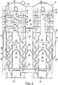
Fig. 2 is a simplified cross-sectional view showing the grain flow paths and certain airflow paths within the exemplary grain dryer ofFig. 1 ; -
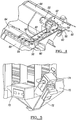
Fig. 3 is an internal view of one of the sub-plenums and showing the elongated airflow openings defined by the panels of the exemplary grain dryer ofFig. 1 ; -
Fig. 4 illustrates a loop paddle conveyor which can be used to feed grain into the top of the grain flow paths in exemplary grain dryer ofFig. 1 ; -
Fig. 5 illustrates a jump drag conveyor by which the output from each metering paddle conveyor can be joined to a single grain output in the exemplary grain dryer ofFig. 1 ; -
Fig. 6 is a simplified perspective view illustrating various airflow paths of the exemplary grain dryer ofFig. 1 ; -
Fig. 7 is a perspective view showing an outer shroud of the fan of the exemplary grain dryer ofFig. 1 ; and -
Fig. 8 is a partial perspective view illustrating the alignment of the upper diverters relative to the lower diverters (substantially perpendicular to each other) and relative to the longitudinal side walls and transverse end walls; and -
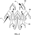
Fig 9 is a perspective view showing the airflow into, thru, and out of the grain column in an upper portion of the grain flow path. - Corresponding reference numerals indicate corresponding parts throughout the several views of the drawings.
- Example embodiments will now be described more fully with reference to the accompanying drawings.
- Referring to
Figs. 1 through 9 , an exemplary embodiment of a continuousflow grain dryer 10 of the present disclosure can generally include an induced draft burner 12 (Fig. 6 ), and a double wide, double inlet centrifugal fan 14 (Fig. 6 ) providing double pass airflow through a plurality of grain columns within grain flow paths 16 (Fig. 2 ). - The illustrated embodiment includes four adjacent
grain flow paths 16 that define four grain columns in use. In this exemplary embodiment, the adjacentgrain flow paths 16 are longitudinally extending and therefore are completely separate from each other. Eachgrain flow path 16 is defined by a pair of longitudinally extendingside walls 95 and a pair ofend walls 94. Adjacentgrain flow paths 16, however, can also exist in a circular grain dryer wherein opposing portions of a circular grain column can be considered to form adjacentgrain flow paths 16. - An upper portion of each
grain flow path 16 includes a plurality of upperelongated grain diverters 88 extending transversely across thegrain flow path 16. These uppertransverse grain diverters 88 can extend substantially perpendicular to theside walls 95 in a side (or elevation) view, or in a top (or plan) view, or in both side and plan views. Theseupper grain diverters 88 can have a generally inverted "V" or "U" shaped configuration and can be coupled to opposingside walls 95 at their opposing ends. - These upper
transverse grain diverters 88 can be arranged in a plurality of substantially horizontal rows. Thetransverse diverters 88 of each horizontal row can be offset from each other by fifty percent. In other words, thetransverse diverters 88 in alternating horizontal rows can be vertically aligned and thetransverse diverters 88 of adjacent horizontal rows can be aligned along a plane that is angled to a horizontal plane as seen inFigs. 8 and9 . - A generally
triangular opening 89 in aside wall 95 can be associated with one end of each of thetransverse diverters 88. Specifically, the grain diverters 88 in one horizontal row can be coupled to aside wall 95 to surround the upper portion of atriangular opening 89 in theside wall 95 defining agrain flow path 16. The upper transverse grain diverters 88 in adjacent horizontal rows can be coupled to theopposite side wall 95 defining the samegrain flow path 16 to surround the upper portion of atriangular opening 89 in theopposite side wall 95. - Such a configuration can create an airflow path through a grain column in the
grain flow path 16 as illustrated inFig. 9 . It should be appreciated fromFig. 9 that the air flows into the grain column through an inlet opening 89 in oneside wall 95 at onetransverse diverter 88 as indicated byarrow 47 and then can exit through an outlet opening 89 in theopposite side wall 95 associated with or at adifferent diverter 88 as indicated byarrow 49. In addition, theinlet openings 89 can be provided at first alternating horizontal rows oftransverse diverters 88a, while theexit openings 89 can be provided at second alternating rows of thetransverse diverters 88b interspersed therebetween. AlthoughFig. 9 has been simplified to show only three rows of diverters, six or seven, or a different plurality of rows ofdiverters 88 andopenings 89 can be provided. - Not only can this
upper portion 17 of thegrain flow paths 16 have thetransverse diverters 88, but theupper portion 17 can also have a relatively large cross-sectional area relative to the lower portion 19 (detailed hereinafter) of thegrain flow paths 16. This additional cross-sectional area can be provided by providing a larger transverse distance between theopposing side walls 95 defining eachgrain flow path 16 in theupper portion 17, than in thelower portion 19. This can enable a larger volume of grain to be resident in theupper portion 17 of thegrain column 16 than in thelower portion 19. The relatively larger cross sectional area of width can also enable a larger residence time per vertical foot (30.48 cm) of movement for the grain in theupper portion 17 of thegrain column 16 than in thelower portion 19. - In the
lower portion 19 of eachgrain flow path 16 each of the grain columns can result from an undulatinggrain flow path 16. Thegrain flow path 16 is defined by opposing sets of a plurality of longitudinally
extendingpanels 18. The longitudinally extendingpanels 18 have a lower portion that is angled transversely downwardly and toward the center of thegrain flow path 16 to provide lowerelongated grain diverters 98, which act as moisture equalizers. - The
lower grain diverters 98 extend longitudinally along alternating sides of thegran flow path 16 or grain column between the opposing pair of end walls that define thegrain flow path 16. Thelower grain diverters 18 can extend longitudinally in a direction substantially parallel to theside walls 95 in a top (or plan) view. Thus, thelower grain diverters 18 can extend longitudinally in a direction that is substantially perpendicular to the longitudinal direction of theupper grain diverters 88 in top (or plan) view, or in side (or elevation) view, or in both side and plan views. - As should be apparent from the above description, the
upper grain diverters 88 can tend to distribute grain fines along transverse lines extending the width of theupper portion 17 of the grain column, or substantially perpendicular to theside walls 95. In contrast, thelower grain diverters 98 can tend to distribute grain fines along longitudinal lines substantially parallel to theside walls 95. As a result, the grain fines can remain more evenly distributed throughout the grain column as the grain flows from the top of thegrain flow path 16 to its bottom. - The
angled panels 18 of each opposingside wall 95 are vertically spaced apart from each other forming upwardly facing elongated openings 20 (seen best inFig. 3 with grain present) between verticallyadjacent panels 18.Elongated openings 20 allow airflow to pass through onelateral side wall 95 of eachgrain flow path 16 betweenpanels 18, through centrally located undulatinggrain flow path 16, and out of thegrain flow path 16 throughelongated openings 20 of the opposinglateral side wall 95. - A
central air plenum 22 is located in the space between a pair of grain flow paths 16 (a first and second grain flow path 16) on the left inFig. 2 . An additionalcentral air plenum 22 is positioned in the space between another pair (a third and fourth grain flow path 16) on the right inFig. 2 . The sides of eachcentral air plenum 22 are laterally defined byinner side walls 95 of adjacentgrain flow paths 16 in the pair. - Each
central air plenum 22 can include adivider 26 separatingcentral plenum 22 into two sub-plenums. The upper sub-plenum can be aheat plenum 32. The high pressure (or positive pressure), high heat airflow fromfan 14 first flows intoheat plenum 32 ofcentral plenum 22. Sub-plenum belowheat plenum 32 can be areturn plenum 34. Air which has passed through a grain column in one of thegrain flow paths 16 can be pulled fromreturn plenum 34 to aninlet 36 offan 14 via a returnflow air duct 38. Thus, the pressure inreturn plenum 34 can be below atmospheric pressure (negative pressure) during operation. -
Enclosures grain flow paths 16 opposite that definingcentral plenum 22.Outer enclosures 40 on opposing sides of the four grain columns can be defined by outer walls 44 (Fig. 6 ).Inner enclosure 42 can be provided in the space between the pairs of grain flow paths 16 (between second and thirdgrain flow paths 16 in this example). Sides ofinner enclosure 42 are partially defined by sets ofpanels 18 forming theside wall 95 opposite those forming thesides walls 95 of thecentral plenum 22. -
Enclosures high heat plenum 32 to capture airflow passing through the lower portion of adjacentgrain flow path 16 fromheat plenum 32 via high heat airflow path represented by two-headedarrow 45.Enclosures arrows 46 that once again passes through an adjacentgrain flow path 16 before being ultimately exhausted to the atmosphere from thegrain dryer 10. -
Enclosures arrows 48 that once again passes through an adjacentgrain flow path 16 and intoreturn plenum 34. Thus, air enteringcentral plenum 22 and passing through the grain flow path into one of theenclosures grain flow path 16 prior to (1) exiting to the atmosphere, or (2) returning viareturn plenum 34 to fan 14 viareturn duct 38 for recirculation. - Air also enters the grain columns from each
heat plenum 32 at the upper portion of thegrain flow paths 16 via thetriangular inlet openings 89 of theside walls 95 defining the high pressure (or positive pressure),heat plenum 32 as indicated by double-headedarrows 47. The air flows into the channel created below the associated generallytriangular diverter 88. The air then flows through the grain column as seen inFig. 9 , and then out a triangular outlet opening 89 of the opposingside wall 95 defining thegrain flow path 16. The air exiting of theupper portion 17 through the uppertriangular outlet openings 89 is exhausted to the atmosphere directly or viaexhaust plenum 28 between the pairs of grain columns abovedivider 24 definingenclosure 42. Thiscentral exhaust plenum 28 is open to the atmosphere viaopenings 30 in theend walls 94 as best seen inFig. 1 . This provides a pre-heat zone in theupper portion 17 of the grain column as described hereinafter. - Referring to
Figure 4 , a loopdrag input conveyor 52 including grain paddles 54 can be provided. Amotor 55 drives loopdrag input conveyor 52.Paddles 54 are positioned in a loop above twoupper shelves 56 extending the length of thegrain flow paths 16. Eachshelf 52 can includeperiodic openings 58 allowing grain to fall through theshelf 52. Additionally or alternatively, eachshelf 52 can include downwardly angledwalls 60 along each side ofshelves 52 or belowopenings 58, with eachangled wall 60 extending downwardly toward the top of one of thegrain flow paths 16. Thus, each downwardly angledwall 60 can be configured to direct grain from shelves 52 (e.g., over a side or through an opening 58) into the top of one of thegrain flow paths 16. A connectingshelf 62 can connect the two upper shelves together at each end ofgrain dryer 10 to complete the loop arrangement ofdrag conveyor 52. - A cover can be provided over
loop drag conveyor 52, which includes a plurality ofpanels 64. The loop arrangement ofdrag conveyor 52 allows grain to be added to thecontinuous flow dryer 10 at essentially any point along the loop. For example, anycover panel 64 can simply be removed to create a grain input opening to feed grain toloop drag conveyer 52 by which the pairs ofgrain flow paths 16 are fed. Alternatively, acover panel 64 including a grain input opening therethrough (not shown) can simply be placed at any point along the loop to feedconveyor 52. Thus, a grain input opening can be located at either end ofgrain dryer 10, or at any point along either lateral side ofgrain dryer 10. It can be desirable in some instances to disposemotor 55 opposite in the loop from the location of the grain input. For example, the bothmotor 55 and the grain input can be on opposite sides at one end of the grain dryer, so that the inputted grain flows along a "U" shape path prior to encounteringmotor 55 coupled to the paddle drive. - Referring to
Figure 2 ,shelves 56 and downwardly angledwalls 60 by which grain flows intograin flow paths 16 can be seen. This allows grain to flow into each of thegrain flow paths 16 between pairs of longitudinally extendingside walls 95 of theupper portion 17. The longitudinally extendingside walls 95 of theupper portion 17 can be formed by a plurality of panels withopenings 89 aligned in horizontal rows as previously described. Also as previously described, theupper portion 17 can have a larger cross-sectional area relative to thelower portion 19 of the grain flow column. - Opposing
panels 18 formingside walls 95 andgrain flow paths 16 can have a smaller width or cross-sectional arealower portion 19 below theupper portion 17 andadjacent return plenum 34 and theheat plenum 32. Inlower portion 19 of thegrain flow path 16 the lateral spacing between opposingpanels 18 forming eachgrain flow path 16 can be constant. In addition, the lower end of eachpanel 18 on one side can be vertically aligned with the lower end of opposingpanels 18. Thus, the fact thatangled panels 18 define undulatinggrain flow paths 16 defining a grain column can be understood. - Horizontally extending
elongated airflow openings 20 can also be defined by spaces between verticallyadjacent panels 18 on each side ofgrain flow paths 16. Theseairflow openings 20 between verticallyadjacent panels 18 are present on opposing sides of eachgrain flow path 16.Openings 20 enable airflow through one side of thegrain flow path 16, through a grain column in thepath 16, and out through opposingopenings 20 of the other lateral side of thegrain flow path 16. The relationship between the airflow flowing through a grain column in to and out of various plenums ofcentral plenum 22 is affected by the width ofelongated openings 20 created by the spacing between verticallyadjacent panels 18. The width ofopenings 20 can also be sufficiently large that the exiting airflow speed throughopenings 20 is below that which lifts grain out ofgrain flow path 16 throughopenings 20. Thus, there is no need for any screens on theopenings 20, despite the fact that the width ofopenings 20 is larger than the diameter of grain ingrain flow path 16. The width ofopenings 20 can be many times larger than the average diameter of the grain. For example, the width in some cases can be at least about 25 mm, at least about 50 mm, at least about 75 mm, or at least about 100 mm. - The
divider 26 can also affect the relationship between the airflow flowing through grain columns ingrain flow paths 16 into and out of thecentral plenum 22. For example, thedivider 26 can be coupled to one ofangled panels 18 defining inner (or opposing) walls of adjacentgrain flow paths 16. This helps avoid any airflow path arounddividers heat plenum 32 to an adjacent part ofcentral plenum 22. The width ofelongated openings 20 can also be varied in order to aid in reducing undesirably shortened airflow paths. Differences in the widths of various elongated openings at various locations alonggrain flow paths 16 can be seen in the drawings. Thus, in some instances the width (or height) ofopenings 20 might vary between 20 mm and 100 mm at various locations alonggrain flow paths 16. - In addition,
divider 26 can have a sloped or convex upper central surface and can be attached at an upper end of anangled panel 18 on each side. Thus, any grain that might possibly fall from one ofelongated openings 20 will fall onto the sloped or convex upper surface of thedivider 26, which will guide the grain back into an adjacentgrain flow path 16 via an adjacentelongated opening 20. - Referring to
Figures 2 and5 , an outputmetering drag conveyor 70 can be provided at the bottom of each pair ofgrain flow paths 16. An exemplarymetering drag conveyor 70 which can be used is described in detail inU.S. Patent No. 6,834,442 , incorporated herein, in its entirety, by reference. An terminal end of each outputmetering drag conveyor 70 can include an output that feeds ajump drag mechanism 72 that can joins the outputs of bothmetering drag conveyors 70 into a single grain output collection point. From there adischarge drag conveyor 74 or auger conveyor can be used to discharge the conditioned grain from thegrain dryer 10. - Referring to
Figures 1 ,6 and7 , a combined fan andburner assembly 76 can be positioned at one end ofgrain dryer 10.Assembly 76 can include induceddraft burner 12 positioned between anair intake 78 andcentrifugal fan 14. Thus,fan 14 pulls airflow throughair intake 78 and intofan 14 through afan inlet 36.Fan 14 can be a double wheel, double intake centrifugal fan wherein there is acentral fan intake 36 on each side of thefan 14. A variable frequency drive motor (not shown) can drivefan 14 at variable speeds. - A
shroud 80 on each side ofassembly 76 provides airflow ducting fromburner 12 toinlet 36 offan 14. Eachshroud 80 also provides a portion ofreturn airflow duct 38 for airflow coming fromreturn plenum 34 toinlets 36 offan 14.Shroud 80 can include an outer member with a central opening 82 (Fig. 7 ) adjacent the fan wheel bearings 84 (Fig. 6 ).Central opening 82 inshroud 80 allows unheated air to flow overbearings 84 to cool them. This can greatly reduce negative effects onbearings 82 that might otherwise result from providingburner 12 immediately upstream fromfan 14. - Referring to
Fig. 6 , ambient air entersburner 12 viaair inlet 78.Air exiting burner 12 flows intoinlets 36 at each side offan 14. The air is directed viashroud 80, which defines an air duct betweenburner 12 andinlet 36 on each side offan 14. Thus, a burner airflow path flows throughair inlet 78 toburner 12, passes throughburner 12, and then fromburner 12 flows toinlets 36 offan 14. - Return airflow paths represented by
arrows 86 can provide additional air toinlets 36 offan 38. Eachreturn airflow path 86 travels within areturn air duct 38 from each of thereturn plenums 34 to one of theinlets 36 on either side offan 14. As noted above,shroud 80 can operate as part of thereturn air duct 38, helping to direct air of thereturn airflow paths 86 intoinlets 36 offan 14. As discussed above,shroud 80 can include a central opening 82 (Fig. 7 ) providing a bearing cooling flow path to permit some cooler ambient air to additionally enterinlets 36 offan 14 to flow overfan bearings 84 centrally located in thefan inlet 36. Thus, despite the fact that highly heated air flows intofan inlets 36 directly fromburner 12 via burner airflow path, and return warm airflows intoinlets 36 offan 14 viareturn airflow paths 86, cool air can still flow overfan bearings 84 viacentral opening 82 inshroud 80. - The air from these three flow paths can be thoroughly mixed in
fan 14, thereby outputting air that is of substantially uniform temperature. Fan output airflow paths represented byarrows 90 provide communication between outlet offan 14 and eachheat plenum 32. Fanoutlet airflow paths 90 can be provided by adual duct 92 arrangement as seen inFigure 6 . - Referring to
Fig. 2 , the airflow through grain columns of eachgrain flow path 16 is shown in relation to the left pair ofgrain flow paths 16. It should be understood, however, that the same airflow paths also flow through the other pair of grain columns withingrain flow paths 16 in like manner during operation ofgrain dryer 10. Air first entersheat plenum 32 via fanoutlet flow path 86. - From the lower portion of the
heat plenum 32, air flows outwardly through the grain columns oflower portions 19 of adjacentgrain flow paths 16 into the surroundingenclosures arrow 45. In this case, the leftouter enclosure 40 and theinner enclosure 42. Thus, a heat zone is provided in the grain columns of thelower portion 19 of thegrain flow paths 16adjacent heat plenum 32 due toheat airflow paths 45. - From the upper portion of the
heat plenum 32, air flows into theupper portion 17 of thegrain flow path 16 viainlet openings 89 associated with alternating rows of uppertransverse diverters 88a (Fig. 9 ) as indicated byarrows 47. After flowing through the grain column as shown inFig. 9 , the air can then exit thegrain dryer 10 throughopenings 89 associated with the interspersed alternating rows ofupper grain diverters 88b as indicated byarrows 49. Thus, a pre-heat zone is provided in the grain columns of theupper portion 19 of thegrain flow paths 16adjacent heat plenum 32 due topreheat airflow paths 47. - The relationship between the mass or volume of grain and the total cross-sectional area of the openings (89 and 20) in the upper and lower sections (17 and 19, respectively) create a pressure drop ratio that is approximately 2:1 (upper section pressure drop:lower section pressure drop). Stated another way, the
openings 89 andgrain flow paths 16 are configured to distribute approximately twice the amount of air from theheat plenum 32 into thelower portion 19 than into theupper portion 17 of the grain flow path during operation. - The combination of lower airflow and greater grain mass or volume in the
upper portion 17 ofgrain flow path 16 than in thelower portion 19, results in the grain being gently preheated in the preheat zone of theupper portion 17. The gentle heating of the grain in this pre-heat zone brings the moisture to the surface of the grain without causing it to be trapped within the grain. Likewise, this combination results in the grain being fully heated in the heat zone of thelower portion 19 to drive the moisture out of the grain without it being trapped therein. -
Enclosures airflow paths grain flow path 16 into theupper portion 17 orlower portion 19, respectively. In this way, air passes into the grain columns orgrain flow path 16 twice before being exhausted or returned tofan 14 for recirculation. - For example,
enclosures preheat airflow path 46 through a grain column fromenclosures exhaust plenum 28. The air ofpreheat airflow path 46 is still warm. As a result of thiswarm airflow 46, an extended preheat zone is provided in the grain columns ofgrain flow paths 16adjacent exhaust plenum 28. The preheat zone helps reduce thermal shock as the grain is being heated ingrain dryer 10. Air in theexhaust plenum 28 exits the grain dryer throughexhaust opening 30 in the back wall 94 (Fig. 1 ) ofgrain dryer 10. -
Enclosures temper airflow path 48 through a grain column of adjacentgrain flow paths 16 fromenclosures return plenum 34. Air flowing through a grain column intoreturn plenum 34 fromenclosures return plenum 34 is also still warm. This airflow occurs at an uppermost portion of the grain columnsadjacent return plenum 34, providing a temper zone. The temper zone helps reduce thermal shock as the grain is being cooled ingrain dryer 10. - A cooling zone is next created in grain columns adjacent below the temper zone as a result of ambient air being pulled into
return plenum 34 below temper zone viacooling airflow path 50. In cooling zone, ambient air is pulled intoreturn plenum 34 viacooling airflow path 50 through adjacent grain columns via correspondingopenings 20. Air withinreturn plenum 34 is pulled back into thefan 14 viareturn airflow path 86. Thus, returnair plenum 34 can typically be at a negative pressure during operation. - As a result of the
various airflow paths grain flow paths 16 definingcentral plenum 22, grain is first preheated in preheat zone as a result ofairflow path 47. Then, as grain moves downgrain flow paths 16, the grain is heated in heat zone as a result ofairflow path 45. Continuing downgrain flow paths 16, the grain is next subjected to a temper zone as a result ofairflow path 48, below whichairflow path 50 creates a cooling zone portion of grain columns ingrain flow paths 16 Thus, the grain can be subjected to at least four different treatment zones as it flows down through eachgrain flow path 16. -
Cooling airflow path 50,temper airflow path 48, or both, can pick up fines from the grain column and carry them intoreturn plenum 34 and returnairflow path 86 tofan 14. After passing throughfan 14, any such fines are returned to the grain columns viareturn airflow paths 90 including fanoutput airflow paths 90. Thus, returnairflow path 86 and fanoutput airflow path 90, including throughfan 14, define a recirculating airflow path in which fines might possibly be present. Since the airflow path throughburner 12 is positioned outside the recirculating airflow path, any fines picked up flow through the recirculating airflow path without passing throughburner 12. As discussed above, only fresh ambient air flows throughburner 12 on its way into the recirculating airflow path. Thus, there is no concern about igniting any fines pulled from a grain column. - Air flowing into the
upper portion 17 of the grain column orgrain flow path 16 from thecentral plenum 22 indicated byarrows 47 can pass through the grain as seen inFig. 9 and then out to the atmosphere as indicated byarrows 49. Air entering viaarrows 47 can also flow intoexhaust plenum 28 and can exitgrain dryer 10 to the atmosphere throughexhaust opening 30 in a central location between the adjacent pairs ofgrain flow paths 16 definingexhaust plenum 28 above thecentral divider 24. - Various methods should be apparent from the above discussion and should be considered part of the disclosure. For example, some methods disclosed herein can involve providing various components of
grain dryer 10 disclosed herein. Other methods disclosed herein can involve arranging or connecting various components as disclosed herein. Further methods disclosed herein can involve providing components to create or creating various airflow paths as disclosed herein. Additional methods disclosed herein can involve operating various components as disclosed herein. Providing various components to create the various treatment zones in a grain column are also methods disclosed herein. Moreover, combinations including various aspects of the disclosed methods, including those listed as examples above, are further methods disclosed herein. - The terminology used herein is for the purpose of describing particular example embodiments only and is not intended to be limiting. As used herein, the singular forms "a," "an," and "the" may be intended to include the plural forms as well, unless the context clearly indicates otherwise. The terms "comprises," "comprising," "including," and "having," are inclusive and therefore specify the presence of stated features, integers, steps, operations, elements, and/or components, but do not preclude the presence or addition of one or more other features, integers, steps, operations, elements, components, and/or groups thereof. The method steps, processes, and operations described herein are not to be construed as necessarily requiring their performance in the particular order discussed or illustrated, unless specifically identified as an order of performance. It is also to be understood that additional or alternative steps may be employed.
- Although the terms first, second, third, etc. may be used herein to describe various elements, components, regions, layers and/or sections, these elements, components, regions, layers and/or sections should not be limited by these terms. These terms may be only used to distinguish one element, component, region, layer or section from another region, layer or section. Terms such as "first," "second," and other numerical terms when used herein do not imply a sequence of importance or order unless clearly indicated by the context. Thus, a first element, component, region, layer or section discussed below could be termed a second element, component, region, layer or section without departing from the teachings of the example embodiments.
- The foregoing description of the embodiments has been provided for purposes of illustration and description. It is not intended to be exhaustive or to limit the disclosure. Individual elements or features of a particular embodiment are generally not limited to that particular embodiment, but, where applicable, are interchangeable and can be used in a selected embodiment, even if not specifically shown or described. The same may also be varied in many ways. Such variations are not to be regarded as a departure from the disclosure, and all such modifications are intended to be included within the scope of the disclosure.
Claims (11)
- A continuous flow grain dryer (10) comprising:a pair of grain flow paths (16) through which the grain flows downwardly under the influence of gravity in a grain column; each grain flow path (16) being defined by a pair of longitudinally extending side walls (95) and a pair of transversely extending end walls (94);each grain flow path (16) having an upper portion (17) comprising:a plurality of upper elongated grain diverters (88) extending transversely across the grain flow path (16) between opposing inner faces of the pair of longitudinally extending side walls (95);a first opening (89) in the side walls (95) associated with each upper grain diverter (88);a central air plenum (22) positioned between the pair of grain flow paths (16); anda divider (26) separating the central air plenum (22) into a positive pressure plenum (32) and a negative pressure plenum (34),characterized in that:
each grain flow path (16) has a lower portion (19) comprising:a plurality of lower elongated grain diverters (18) extending longitudinally along alternating sides of the grain flow path (16) between opposing inner faces of the pair of end walls (94);a longitudinally extending second opening (20) in the side walls (95) associated with each lower grain diverter (18). - The continuous grain flow dryer (10) of claim 1, wherein the upper elongated grain diverters (88) are aligned substantially perpendicular in plan view to the longitudinally extending side walls (95), and wherein the lower elongated grain diverters (18) are aligned substantially parallel in plan view to the longitudinally extending side walls (95).
- The continuous grain flow dryer (10) of any of the preceding claims, comprising an enclosure (40, 42) adjacent each opposite side of the pair of grain flow paths (16) that extends to include a plurality of the first openings (89) and a plurality of the longitudinally extending second openings (20), wherein air exiting the plurality of the longitudinally extending second openings (20) enclosed by the enclosure (40, 42) is returned into the first openings (89) enclosed by the enclosure (40, 42).
- The continuous grain flow dryer (10) of any of the preceding claims, wherein the at least one of the first openings (89) in the side walls (95) comprises a first row of the first openings (89) in the side walls (95) associated with a first row of the upper grain diverters (88).
- The continuous grain flow dryer (10) of any of the preceding claims, wherein the upper elongated grain diverters (88) of the upper portion (17) of each grain flow path (16) are arranged vertically offset relative to each other by fifty percent to provide a mixed grain flow within the upper portion (17) of the grain flow path (16).
- The continuous grain flow dryer (10) of any of the preceding claims, wherein, the first openings (89) and upper portions (17) of each grain flow path (16) are sized and shaped relative to the second openings (20) and lower portions (19) of each grain flow path (16) so that during operation, an upper portion pressure drop as airflow passes through the first openings (89) in a first of the pair of longitudinally extending side walls (95), through the grain flow path (16), and out the first openings (89) in a second of the pair of longitudinally extending side walls (95) is about two times that of a lower portion pressure drop as airflow passes through the second openings (20) in the first of the pair of longitudinally extending side walls (95), through the grain flow path (16), and out the second openings (20) in the second of the pair of longitudinally extending side walls (95) and back again out of the second openings (20) in the first of the pair of longitudinally extending side walls (95).
- The continuous grain flow dryer (10) of any of the preceding claims, wherein a total cross sectional area of each of the first and second openings (89, 20) and a width of each of the upper (17) and lower portions (19) of each grain flow path (16) are configured to cause about twice the volume of air to pass through grain in the lower portion (19) as through grain in the upper portion (16) during operation.
- The continuous grain flow dryer (10) of any of the preceding claims, wherein airflow passing from the positive pressure plenum (32) through the upper portion (17) of the pair of grain flow paths (16) creates a preheat zone in the upper portion (17) of the pair of grain flow paths (16) during operation; and wherein airflow passing from the positive pressure plenum (32) through the upper portion (17) of the pair of grain flow path (16) creates a heat zone in the pair of grain flow paths (16) below the preheat zone during operation.
- The continuous grain flow dryer (10) of claim 8, wherein airflow passing from first and second enclosures (40, 42) to the negative pressure plenum (34) creates a temper zone in the pair of grain flow paths (16) below the heat zone, and ambient airflow passing into the negative pressure plenum (34) via the plurality of second openings (20) creates a cooling zone below the temper zone during operation.
- The continuous grain flow dryer (10) of claim 8 or 9, further comprising:a recirculating airflow path (86, 90) from the negative pressure plenum (34) through a fan (14) and back to the positive pressure plenum (32), wherein during operation, the negative pressure plenum (34) is fed by airflow passing through grain columns in the pair of grain flow paths (16); anda burner (12) outside the recirculating airflow path (86, 90) providing heated air to the fan (14) via a burner airflow path that joins to the recirculating airflow path (86, 90), wherein during operation, the burner (12) is fed by ambient airflow from a burner inlet (78) without any recirculating airflow passing through the burner (12).
- The continuous grain flow dryer (10) of any of the preceding claims, wherein the lower elongated grain diverters (18) of the lower portion (19) of each grain flow path (16) are arranged relative to each other to define the lower portion (19) of the of the grain flow path (16) as an undulating grain flow path.
Applications Claiming Priority (2)
| Application Number | Priority Date | Filing Date | Title |
|---|---|---|---|
| US14/179,870 US9835375B2 (en) | 2014-02-13 | 2014-02-13 | Hybrid continuous flow grain dryer |
| PCT/US2015/014776 WO2015123099A1 (en) | 2014-02-13 | 2015-02-06 | Hybrid continuous flow grain dryer |
Publications (2)
| Publication Number | Publication Date |
|---|---|
| EP3105522A1 EP3105522A1 (en) | 2016-12-21 |
| EP3105522B1 true EP3105522B1 (en) | 2019-07-24 |
Family
ID=52472642
Family Applications (1)
| Application Number | Title | Priority Date | Filing Date |
|---|---|---|---|
| EP15704687.1A Active EP3105522B1 (en) | 2014-02-13 | 2015-02-06 | Hybrid continuous flow grain dryer |
Country Status (13)
| Country | Link |
|---|---|
| US (1) | US9835375B2 (en) |
| EP (1) | EP3105522B1 (en) |
| CN (1) | CN105992924A (en) |
| AR (1) | AR099468A1 (en) |
| AU (1) | AU2015217414B2 (en) |
| BR (1) | BR112016018705B1 (en) |
| CA (1) | CA2881714C (en) |
| HU (1) | HUE046188T2 (en) |
| MX (1) | MX2016010336A (en) |
| PH (1) | PH12016501478A1 (en) |
| RU (1) | RU2673303C2 (en) |
| UA (1) | UA121207C2 (en) |
| WO (1) | WO2015123099A1 (en) |
Families Citing this family (12)
| Publication number | Priority date | Publication date | Assignee | Title |
|---|---|---|---|---|
| RU2618638C1 (en) * | 2016-03-24 | 2017-05-05 | Федеральное государственное бюджетное образовательное учреждение высшего образования "Воронежский государственный университет инженерных технологий" (ФГБОУ ВО "ВГУИТ") | Convective drier |
| US10767926B2 (en) * | 2016-04-18 | 2020-09-08 | Sukup Manufacturing Co. | Mixed-flow grain dryer with cross-flow vacuum cool heat recovery system |
| US11193711B2 (en) | 2016-04-18 | 2021-12-07 | Sukup Manufacturing Co. | Bridge reducing mixed-flow grain dryer with cross-flow vacuum cool heat recovery system |
| US10378820B2 (en) | 2016-04-18 | 2019-08-13 | Sukup Manufacturing Co. | Mixed flow grain dryer with vacuum cool heat recovery system |
| WO2017197229A1 (en) * | 2016-05-12 | 2017-11-16 | The Gsi Group Llc | Agricultural dryer with mixed-flow fan |
| RU2663595C1 (en) * | 2017-07-10 | 2018-08-07 | Владимир Геннадьевич Чумаков | Chamber grain drier |
| CN107576190B (en) * | 2017-07-31 | 2019-08-06 | 新兴能源装备股份有限公司 | A kind of tower drier that waste heat from tail gas recycles |
| CN107906932A (en) * | 2017-09-19 | 2018-04-13 | 合肥市凯佳机械加工有限公司 | A kind of new drying tower drying layer |
| CN107702511B (en) * | 2017-11-23 | 2022-11-25 | 湖北金炉节能股份有限公司 | Clean moulded coal desiccator of inner loop |
| RU2732560C1 (en) * | 2019-08-26 | 2020-09-21 | Федеральное государственное бюджетное научное учреждение "Федеральный научный агроинженерный центр ВИМ" (ФГБНУ ФНАЦ ВИМ) | Device for double-flow drying of seeds and grains |
| RU200852U1 (en) * | 2020-07-16 | 2020-11-13 | Общество С Ограниченной Ответственностью "Всм Инвест" (Ооо "Всм Инвест") | Shaft louver grain dryer |
| RU200524U1 (en) * | 2020-07-16 | 2020-10-28 | Николай Николаевич Копылов | GRAIN DRYER |
Citations (1)
| Publication number | Priority date | Publication date | Assignee | Title |
|---|---|---|---|---|
| US731682A (en) * | 1901-09-28 | 1903-06-23 | Otto Moritz Hillig | Drying or cooling apparatus. |
Family Cites Families (25)
| Publication number | Priority date | Publication date | Assignee | Title |
|---|---|---|---|---|
| GB240533A (en) | 1924-07-01 | 1925-10-01 | Robert Arthur Smith | Improvements relating to apparatus for cooking, roasting, drying or sterilising edible nuts, oil seeds, and other granular materials |
| US2434202A (en) | 1944-04-01 | 1948-01-06 | Socony Vacuum Oil Co Inc | Method and apparatus for contacting gases with particle form solid contact materials |
| US3238637A (en) | 1961-12-22 | 1966-03-08 | Massey Ferguson Inc | Grain dryer |
| US3629954A (en) | 1968-09-26 | 1971-12-28 | Hart Carter Co | Gravity flow grain dries |
| DE2744449C2 (en) | 1976-10-05 | 1985-05-23 | Westlake Agricultural Engineering Inc., St. Marys, Ontario | Device for controlling the flow of granular material through a drying tower |
| SU635382A1 (en) | 1977-06-14 | 1978-11-30 | Всесоюзный Ордена Трудового Красного Знамени Научно-Исследовательский Институт Зерна И Продуктов Его Переработки | Heat exchanger for cooling and final drying of fluent materials |
| US4149844A (en) | 1977-09-08 | 1979-04-17 | Beard Industries, Inc. | Optimum continuous flow grain drying and conditioning method and apparatus |
| US4249891A (en) | 1978-09-14 | 1981-02-10 | Beard Industries, Inc. | Advanced optimum continuous crossflow grain drying and conditioning method and apparatus |
| US4268971A (en) | 1979-10-09 | 1981-05-26 | Noyes Ronald T | Optimum low profile continuous crossflow grain drying and conditioning method and apparatus |
| US4404756A (en) | 1981-06-12 | 1983-09-20 | Beard Industries, Inc. | Grain drying and conditioning apparatus |
| US4424634A (en) | 1981-06-19 | 1984-01-10 | Westelaken C | Modular column dryer for particulate material |
| FR2514878A1 (en) | 1981-10-20 | 1983-04-22 | Renault Tech Now | MODULAR DRYER FOR GRAIN DRYING |
| SU1285284A1 (en) | 1984-06-26 | 1987-01-23 | Всесоюзный научно-исследовательский институт зерна и продуктов его переработки | Heat exchanger for cooling loose materials |
| SU1267144A1 (en) | 1984-12-25 | 1986-10-30 | Украинский Филиал Всесоюзного Научно-Исследовательского Института Комбикормовой Промышленности | Apparatus for heat treatment of loose materials |
| US4914834A (en) | 1989-04-11 | 1990-04-10 | Sime Sylvan H | Grain dryer |
| SU1703933A1 (en) * | 1989-12-25 | 1992-01-07 | В.И. Лобанов, Н.И. Капустин, В.И. Подол ко и В.И. Косткж | Shaft drier |
| US5467535A (en) | 1994-05-25 | 1995-11-21 | Beard Industries, Inc. | Moisture equalizer for a continuous flow grain dryer |
| BR9705550A (en) | 1997-11-26 | 2000-05-16 | Dryexcel Manutencao De Equipam | Oblique cross-flow grain dryer |
| US6209223B1 (en) | 1998-12-08 | 2001-04-03 | Advanced Dryer Systems, Inc. | Grain drying system with high efficiency dehumidifier and modular drying bin |
| US6122838A (en) | 1999-09-09 | 2000-09-26 | Beard Industries | Method and apparatus for drying grain |
| RU20373U1 (en) * | 2001-04-27 | 2001-10-27 | Открытое акционерное общество Новосибирский опытно-экспериментальный завод нестандартизированного оборудования | DRYER FOR BULK MATERIALS |
| US6834443B2 (en) | 2003-02-11 | 2004-12-28 | Ctb Ip, Inc. | Full heat moving target grain drying system |
| US6834442B1 (en) | 2003-08-12 | 2004-12-28 | Ctb Ip, Inc. | Conveyor for grain dryer |
| RU2377488C1 (en) * | 2008-10-16 | 2009-12-27 | Государственное образовательное учреждение высшего профессионального образования Воронежская государственная технологическая академия | Convection drier |
| CA2772976A1 (en) * | 2011-07-12 | 2013-01-12 | Ctb, Inc. | Grain dryer with double pass airflow |
-
2014
- 2014-02-13 US US14/179,870 patent/US9835375B2/en active Active
-
2015
- 2015-02-06 CN CN201580008348.8A patent/CN105992924A/en active Pending
- 2015-02-06 BR BR112016018705-9A patent/BR112016018705B1/en active IP Right Grant
- 2015-02-06 AU AU2015217414A patent/AU2015217414B2/en active Active
- 2015-02-06 MX MX2016010336A patent/MX2016010336A/en active IP Right Grant
- 2015-02-06 EP EP15704687.1A patent/EP3105522B1/en active Active
- 2015-02-06 WO PCT/US2015/014776 patent/WO2015123099A1/en active Application Filing
- 2015-02-06 UA UAA201609126A patent/UA121207C2/en unknown
- 2015-02-06 RU RU2016132593A patent/RU2673303C2/en active
- 2015-02-06 HU HUE15704687A patent/HUE046188T2/en unknown
- 2015-02-09 CA CA2881714A patent/CA2881714C/en active Active
- 2015-02-12 AR ARP150100406A patent/AR099468A1/en active IP Right Grant
-
2016
- 2016-07-27 PH PH12016501478A patent/PH12016501478A1/en unknown
Patent Citations (1)
| Publication number | Priority date | Publication date | Assignee | Title |
|---|---|---|---|---|
| US731682A (en) * | 1901-09-28 | 1903-06-23 | Otto Moritz Hillig | Drying or cooling apparatus. |
Also Published As
| Publication number | Publication date |
|---|---|
| CN105992924A (en) | 2016-10-05 |
| RU2016132593A (en) | 2018-03-19 |
| RU2016132593A3 (en) | 2018-09-26 |
| AR099468A1 (en) | 2016-07-27 |
| BR112016018705A2 (en) | 2017-08-08 |
| CA2881714A1 (en) | 2015-08-13 |
| UA121207C2 (en) | 2020-04-27 |
| RU2673303C2 (en) | 2018-11-23 |
| PH12016501478B1 (en) | 2016-08-22 |
| AU2015217414B2 (en) | 2019-02-14 |
| WO2015123099A1 (en) | 2015-08-20 |
| AU2015217414A1 (en) | 2016-09-01 |
| MX2016010336A (en) | 2016-11-30 |
| US20150226482A1 (en) | 2015-08-13 |
| HUE046188T2 (en) | 2020-02-28 |
| US9835375B2 (en) | 2017-12-05 |
| CA2881714C (en) | 2021-11-02 |
| EP3105522A1 (en) | 2016-12-21 |
| BR112016018705B1 (en) | 2022-09-20 |
| PH12016501478A1 (en) | 2016-08-22 |
Similar Documents
| Publication | Publication Date | Title |
|---|---|---|
| EP3105522B1 (en) | Hybrid continuous flow grain dryer | |
| US20130014404A1 (en) | Grain dryer with double pass airflow | |
| US7963048B2 (en) | Dual path kiln | |
| RU2739512C2 (en) | Grain dryer with mixed flow with vacuum cool heat recovery system | |
| US4534780A (en) | Apparatus for heat treatment of objects by convection | |
| CN107388791A (en) | A kind of Multi-layer belt type foodstuff dryer | |
| JP5075827B2 (en) | Apparatus for processing elongated food products with a conditioned air stream | |
| US20060272172A1 (en) | Dual path kiln | |
| RU2008138139A (en) | SHAFT DRYER WITH AIR CIRCUIT BREAKER SYSTEM | |
| DE202007016918U1 (en) | Universal drying device | |
| US4479310A (en) | Continuous dehydration device and process | |
| JP4382725B2 (en) | Food heating equipment | |
| US10912317B2 (en) | Thermal processing apparatus | |
| BR112020018344A2 (en) | METHOD AND DEVICE FOR DRYING PLATES | |
| CN115003974A (en) | Dryer for ceramic tiles or slabs | |
| CN115769039A (en) | Drying machine with cooling function | |
| JP2598669B2 (en) | Poultry house with chicken dung drying mechanism | |
| CN207247816U (en) | A kind of Multi-layer belt type foodstuff dryer | |
| US11964823B2 (en) | Thermal processing apparatus | |
| JP7102655B2 (en) | Nozzle box for drying equipment to dry board-like material | |
| JPH1084899A (en) | Food cooling or drying device | |
| KR20240014698A (en) | The high speed drying system having multi-stage structure | |
| EA040356B1 (en) | METHOD AND DEVICE FOR DRYING PLATES | |
| EA040384B1 (en) | NOZZLE APPARATUS FOR DRYING DEVICE FOR DRYING MATERIALS IN THE FORM OF PLATES | |
| CA2479070A1 (en) | Multi-zone, multi-conveyor dryer and conversion methods and kit |
Legal Events
| Date | Code | Title | Description |
|---|---|---|---|
| PUAI | Public reference made under article 153(3) epc to a published international application that has entered the european phase |
Free format text: ORIGINAL CODE: 0009012 |
|
| STAA | Information on the status of an ep patent application or granted ep patent |
Free format text: STATUS: REQUEST FOR EXAMINATION WAS MADE |
|
| 17P | Request for examination filed |
Effective date: 20160818 |
|
| AK | Designated contracting states |
Kind code of ref document: A1 Designated state(s): AL AT BE BG CH CY CZ DE DK EE ES FI FR GB GR HR HU IE IS IT LI LT LU LV MC MK MT NL NO PL PT RO RS SE SI SK SM TR |
|
| AX | Request for extension of the european patent |
Extension state: BA ME |
|
| DAX | Request for extension of the european patent (deleted) | ||
| STAA | Information on the status of an ep patent application or granted ep patent |
Free format text: STATUS: EXAMINATION IS IN PROGRESS |
|
| 17Q | First examination report despatched |
Effective date: 20170929 |
|
| GRAP | Despatch of communication of intention to grant a patent |
Free format text: ORIGINAL CODE: EPIDOSNIGR1 |
|
| STAA | Information on the status of an ep patent application or granted ep patent |
Free format text: STATUS: GRANT OF PATENT IS INTENDED |
|
| INTG | Intention to grant announced |
Effective date: 20190215 |
|
| GRAS | Grant fee paid |
Free format text: ORIGINAL CODE: EPIDOSNIGR3 |
|
| GRAA | (expected) grant |
Free format text: ORIGINAL CODE: 0009210 |
|
| STAA | Information on the status of an ep patent application or granted ep patent |
Free format text: STATUS: THE PATENT HAS BEEN GRANTED |
|
| AK | Designated contracting states |
Kind code of ref document: B1 Designated state(s): AL AT BE BG CH CY CZ DE DK EE ES FI FR GB GR HR HU IE IS IT LI LT LU LV MC MK MT NL NO PL PT RO RS SE SI SK SM TR |
|
| REG | Reference to a national code |
Ref country code: GB Ref legal event code: FG4D |
|
| REG | Reference to a national code |
Ref country code: CH Ref legal event code: EP |
|
| REG | Reference to a national code |
Ref country code: DE Ref legal event code: R096 Ref document number: 602015034234 Country of ref document: DE |
|
| REG | Reference to a national code |
Ref country code: AT Ref legal event code: REF Ref document number: 1158691 Country of ref document: AT Kind code of ref document: T Effective date: 20190815 |
|
| REG | Reference to a national code |
Ref country code: IE Ref legal event code: FG4D |
|
| REG | Reference to a national code |
Ref country code: NL Ref legal event code: MP Effective date: 20190724 |
|
| REG | Reference to a national code |
Ref country code: LT Ref legal event code: MG4D |
|
| REG | Reference to a national code |
Ref country code: AT Ref legal event code: MK05 Ref document number: 1158691 Country of ref document: AT Kind code of ref document: T Effective date: 20190724 |
|
| PG25 | Lapsed in a contracting state [announced via postgrant information from national office to epo] |
Ref country code: AT Free format text: LAPSE BECAUSE OF FAILURE TO SUBMIT A TRANSLATION OF THE DESCRIPTION OR TO PAY THE FEE WITHIN THE PRESCRIBED TIME-LIMIT Effective date: 20190724 Ref country code: BG Free format text: LAPSE BECAUSE OF FAILURE TO SUBMIT A TRANSLATION OF THE DESCRIPTION OR TO PAY THE FEE WITHIN THE PRESCRIBED TIME-LIMIT Effective date: 20191024 Ref country code: SE Free format text: LAPSE BECAUSE OF FAILURE TO SUBMIT A TRANSLATION OF THE DESCRIPTION OR TO PAY THE FEE WITHIN THE PRESCRIBED TIME-LIMIT Effective date: 20190724 Ref country code: NL Free format text: LAPSE BECAUSE OF FAILURE TO SUBMIT A TRANSLATION OF THE DESCRIPTION OR TO PAY THE FEE WITHIN THE PRESCRIBED TIME-LIMIT Effective date: 20190724 Ref country code: PT Free format text: LAPSE BECAUSE OF FAILURE TO SUBMIT A TRANSLATION OF THE DESCRIPTION OR TO PAY THE FEE WITHIN THE PRESCRIBED TIME-LIMIT Effective date: 20191125 Ref country code: HR Free format text: LAPSE BECAUSE OF FAILURE TO SUBMIT A TRANSLATION OF THE DESCRIPTION OR TO PAY THE FEE WITHIN THE PRESCRIBED TIME-LIMIT Effective date: 20190724 Ref country code: LT Free format text: LAPSE BECAUSE OF FAILURE TO SUBMIT A TRANSLATION OF THE DESCRIPTION OR TO PAY THE FEE WITHIN THE PRESCRIBED TIME-LIMIT Effective date: 20190724 Ref country code: FI Free format text: LAPSE BECAUSE OF FAILURE TO SUBMIT A TRANSLATION OF THE DESCRIPTION OR TO PAY THE FEE WITHIN THE PRESCRIBED TIME-LIMIT Effective date: 20190724 Ref country code: NO Free format text: LAPSE BECAUSE OF FAILURE TO SUBMIT A TRANSLATION OF THE DESCRIPTION OR TO PAY THE FEE WITHIN THE PRESCRIBED TIME-LIMIT Effective date: 20191024 |
|
| PG25 | Lapsed in a contracting state [announced via postgrant information from national office to epo] |
Ref country code: LV Free format text: LAPSE BECAUSE OF FAILURE TO SUBMIT A TRANSLATION OF THE DESCRIPTION OR TO PAY THE FEE WITHIN THE PRESCRIBED TIME-LIMIT Effective date: 20190724 Ref country code: GR Free format text: LAPSE BECAUSE OF FAILURE TO SUBMIT A TRANSLATION OF THE DESCRIPTION OR TO PAY THE FEE WITHIN THE PRESCRIBED TIME-LIMIT Effective date: 20191025 Ref country code: ES Free format text: LAPSE BECAUSE OF FAILURE TO SUBMIT A TRANSLATION OF THE DESCRIPTION OR TO PAY THE FEE WITHIN THE PRESCRIBED TIME-LIMIT Effective date: 20190724 Ref country code: IS Free format text: LAPSE BECAUSE OF FAILURE TO SUBMIT A TRANSLATION OF THE DESCRIPTION OR TO PAY THE FEE WITHIN THE PRESCRIBED TIME-LIMIT Effective date: 20191124 Ref country code: RS Free format text: LAPSE BECAUSE OF FAILURE TO SUBMIT A TRANSLATION OF THE DESCRIPTION OR TO PAY THE FEE WITHIN THE PRESCRIBED TIME-LIMIT Effective date: 20190724 Ref country code: AL Free format text: LAPSE BECAUSE OF FAILURE TO SUBMIT A TRANSLATION OF THE DESCRIPTION OR TO PAY THE FEE WITHIN THE PRESCRIBED TIME-LIMIT Effective date: 20190724 |
|
| REG | Reference to a national code |
Ref country code: HU Ref legal event code: AG4A Ref document number: E046188 Country of ref document: HU |
|
| PG25 | Lapsed in a contracting state [announced via postgrant information from national office to epo] |
Ref country code: TR Free format text: LAPSE BECAUSE OF FAILURE TO SUBMIT A TRANSLATION OF THE DESCRIPTION OR TO PAY THE FEE WITHIN THE PRESCRIBED TIME-LIMIT Effective date: 20190724 |
|
| PG25 | Lapsed in a contracting state [announced via postgrant information from national office to epo] |
Ref country code: DK Free format text: LAPSE BECAUSE OF FAILURE TO SUBMIT A TRANSLATION OF THE DESCRIPTION OR TO PAY THE FEE WITHIN THE PRESCRIBED TIME-LIMIT Effective date: 20190724 Ref country code: IT Free format text: LAPSE BECAUSE OF FAILURE TO SUBMIT A TRANSLATION OF THE DESCRIPTION OR TO PAY THE FEE WITHIN THE PRESCRIBED TIME-LIMIT Effective date: 20190724 Ref country code: EE Free format text: LAPSE BECAUSE OF FAILURE TO SUBMIT A TRANSLATION OF THE DESCRIPTION OR TO PAY THE FEE WITHIN THE PRESCRIBED TIME-LIMIT Effective date: 20190724 Ref country code: RO Free format text: LAPSE BECAUSE OF FAILURE TO SUBMIT A TRANSLATION OF THE DESCRIPTION OR TO PAY THE FEE WITHIN THE PRESCRIBED TIME-LIMIT Effective date: 20190724 Ref country code: PL Free format text: LAPSE BECAUSE OF FAILURE TO SUBMIT A TRANSLATION OF THE DESCRIPTION OR TO PAY THE FEE WITHIN THE PRESCRIBED TIME-LIMIT Effective date: 20190724 |
|
| PG25 | Lapsed in a contracting state [announced via postgrant information from national office to epo] |
Ref country code: IS Free format text: LAPSE BECAUSE OF FAILURE TO SUBMIT A TRANSLATION OF THE DESCRIPTION OR TO PAY THE FEE WITHIN THE PRESCRIBED TIME-LIMIT Effective date: 20200224 Ref country code: SK Free format text: LAPSE BECAUSE OF FAILURE TO SUBMIT A TRANSLATION OF THE DESCRIPTION OR TO PAY THE FEE WITHIN THE PRESCRIBED TIME-LIMIT Effective date: 20190724 Ref country code: CZ Free format text: LAPSE BECAUSE OF FAILURE TO SUBMIT A TRANSLATION OF THE DESCRIPTION OR TO PAY THE FEE WITHIN THE PRESCRIBED TIME-LIMIT Effective date: 20190724 Ref country code: SM Free format text: LAPSE BECAUSE OF FAILURE TO SUBMIT A TRANSLATION OF THE DESCRIPTION OR TO PAY THE FEE WITHIN THE PRESCRIBED TIME-LIMIT Effective date: 20190724 |
|
| REG | Reference to a national code |
Ref country code: DE Ref legal event code: R097 Ref document number: 602015034234 Country of ref document: DE |
|
| PLBE | No opposition filed within time limit |
Free format text: ORIGINAL CODE: 0009261 |
|
| STAA | Information on the status of an ep patent application or granted ep patent |
Free format text: STATUS: NO OPPOSITION FILED WITHIN TIME LIMIT |
|
| PG2D | Information on lapse in contracting state deleted |
Ref country code: IS |
|
| 26N | No opposition filed |
Effective date: 20200603 |
|
| PG25 | Lapsed in a contracting state [announced via postgrant information from national office to epo] |
Ref country code: SI Free format text: LAPSE BECAUSE OF FAILURE TO SUBMIT A TRANSLATION OF THE DESCRIPTION OR TO PAY THE FEE WITHIN THE PRESCRIBED TIME-LIMIT Effective date: 20190724 |
|
| REG | Reference to a national code |
Ref country code: DE Ref legal event code: R119 Ref document number: 602015034234 Country of ref document: DE |
|
| REG | Reference to a national code |
Ref country code: CH Ref legal event code: PL |
|
| GBPC | Gb: european patent ceased through non-payment of renewal fee |
Effective date: 20200206 |
|
| REG | Reference to a national code |
Ref country code: BE Ref legal event code: MM Effective date: 20200229 |
|
| PG25 | Lapsed in a contracting state [announced via postgrant information from national office to epo] |
Ref country code: MC Free format text: LAPSE BECAUSE OF FAILURE TO SUBMIT A TRANSLATION OF THE DESCRIPTION OR TO PAY THE FEE WITHIN THE PRESCRIBED TIME-LIMIT Effective date: 20190724 Ref country code: LU Free format text: LAPSE BECAUSE OF NON-PAYMENT OF DUE FEES Effective date: 20200206 |
|
| PG25 | Lapsed in a contracting state [announced via postgrant information from national office to epo] |
Ref country code: CH Free format text: LAPSE BECAUSE OF NON-PAYMENT OF DUE FEES Effective date: 20200229 Ref country code: LI Free format text: LAPSE BECAUSE OF NON-PAYMENT OF DUE FEES Effective date: 20200229 |
|
| PG25 | Lapsed in a contracting state [announced via postgrant information from national office to epo] |
Ref country code: GB Free format text: LAPSE BECAUSE OF NON-PAYMENT OF DUE FEES Effective date: 20200206 Ref country code: FR Free format text: LAPSE BECAUSE OF NON-PAYMENT OF DUE FEES Effective date: 20200229 Ref country code: IE Free format text: LAPSE BECAUSE OF NON-PAYMENT OF DUE FEES Effective date: 20200206 Ref country code: DE Free format text: LAPSE BECAUSE OF NON-PAYMENT OF DUE FEES Effective date: 20200901 |
|
| PG25 | Lapsed in a contracting state [announced via postgrant information from national office to epo] |
Ref country code: BE Free format text: LAPSE BECAUSE OF NON-PAYMENT OF DUE FEES Effective date: 20200229 |
|
| PG25 | Lapsed in a contracting state [announced via postgrant information from national office to epo] |
Ref country code: MT Free format text: LAPSE BECAUSE OF FAILURE TO SUBMIT A TRANSLATION OF THE DESCRIPTION OR TO PAY THE FEE WITHIN THE PRESCRIBED TIME-LIMIT Effective date: 20190724 Ref country code: CY Free format text: LAPSE BECAUSE OF FAILURE TO SUBMIT A TRANSLATION OF THE DESCRIPTION OR TO PAY THE FEE WITHIN THE PRESCRIBED TIME-LIMIT Effective date: 20190724 |
|
| PG25 | Lapsed in a contracting state [announced via postgrant information from national office to epo] |
Ref country code: MK Free format text: LAPSE BECAUSE OF FAILURE TO SUBMIT A TRANSLATION OF THE DESCRIPTION OR TO PAY THE FEE WITHIN THE PRESCRIBED TIME-LIMIT Effective date: 20190724 |
|
| PGFP | Annual fee paid to national office [announced via postgrant information from national office to epo] |
Ref country code: HU Payment date: 20230126 Year of fee payment: 9 |