EP3105384B1 - Système de fixation structurel - Google Patents
Système de fixation structurel Download PDFInfo
- Publication number
- EP3105384B1 EP3105384B1 EP15748609.3A EP15748609A EP3105384B1 EP 3105384 B1 EP3105384 B1 EP 3105384B1 EP 15748609 A EP15748609 A EP 15748609A EP 3105384 B1 EP3105384 B1 EP 3105384B1
- Authority
- EP
- European Patent Office
- Prior art keywords
- unit
- locking
- hollow tube
- pair
- attachment system
- Prior art date
- Legal status (The legal status is an assumption and is not a legal conclusion. Google has not performed a legal analysis and makes no representation as to the accuracy of the status listed.)
- Not-in-force
Links
- 239000000203 mixture Substances 0.000 claims description 13
- 239000000463 material Substances 0.000 description 3
- 239000002131 composite material Substances 0.000 description 2
- 238000004519 manufacturing process Methods 0.000 description 2
- 239000004033 plastic Substances 0.000 description 2
- 229920003023 plastic Polymers 0.000 description 2
- 241000238631 Hexapoda Species 0.000 description 1
- 229910000831 Steel Inorganic materials 0.000 description 1
- 230000004888 barrier function Effects 0.000 description 1
- 238000005219 brazing Methods 0.000 description 1
- 239000003518 caustics Substances 0.000 description 1
- 239000004567 concrete Substances 0.000 description 1
- 239000000470 constituent Substances 0.000 description 1
- 238000010276 construction Methods 0.000 description 1
- 239000004035 construction material Substances 0.000 description 1
- 230000006866 deterioration Effects 0.000 description 1
- 238000009408 flooring Methods 0.000 description 1
- 239000003292 glue Substances 0.000 description 1
- 238000009413 insulation Methods 0.000 description 1
- JEIPFZHSYJVQDO-UHFFFAOYSA-N iron(III) oxide Inorganic materials O=[Fe]O[Fe]=O JEIPFZHSYJVQDO-UHFFFAOYSA-N 0.000 description 1
- 230000007774 longterm Effects 0.000 description 1
- 239000002184 metal Substances 0.000 description 1
- 239000010959 steel Substances 0.000 description 1
- XLYOFNOQVPJJNP-UHFFFAOYSA-N water Substances O XLYOFNOQVPJJNP-UHFFFAOYSA-N 0.000 description 1
- 238000003466 welding Methods 0.000 description 1
- 239000002023 wood Substances 0.000 description 1
Images

Classifications
-
- E—FIXED CONSTRUCTIONS
- E04—BUILDING
- E04B—GENERAL BUILDING CONSTRUCTIONS; WALLS, e.g. PARTITIONS; ROOFS; FLOORS; CEILINGS; INSULATION OR OTHER PROTECTION OF BUILDINGS
- E04B2/00—Walls, e.g. partitions, for buildings; Wall construction with regard to insulation; Connections specially adapted to walls
- E04B2/56—Load-bearing walls of framework or pillarwork; Walls incorporating load-bearing elongated members
- E04B2/58—Load-bearing walls of framework or pillarwork; Walls incorporating load-bearing elongated members with elongated members of metal
- E04B2/60—Load-bearing walls of framework or pillarwork; Walls incorporating load-bearing elongated members with elongated members of metal characterised by special cross-section of the elongated members
-
- F—MECHANICAL ENGINEERING; LIGHTING; HEATING; WEAPONS; BLASTING
- F16—ENGINEERING ELEMENTS AND UNITS; GENERAL MEASURES FOR PRODUCING AND MAINTAINING EFFECTIVE FUNCTIONING OF MACHINES OR INSTALLATIONS; THERMAL INSULATION IN GENERAL
- F16B—DEVICES FOR FASTENING OR SECURING CONSTRUCTIONAL ELEMENTS OR MACHINE PARTS TOGETHER, e.g. NAILS, BOLTS, CIRCLIPS, CLAMPS, CLIPS OR WEDGES; JOINTS OR JOINTING
- F16B7/00—Connections of rods or tubes, e.g. of non-circular section, mutually, including resilient connections
-
- E—FIXED CONSTRUCTIONS
- E04—BUILDING
- E04B—GENERAL BUILDING CONSTRUCTIONS; WALLS, e.g. PARTITIONS; ROOFS; FLOORS; CEILINGS; INSULATION OR OTHER PROTECTION OF BUILDINGS
- E04B1/00—Constructions in general; Structures which are not restricted either to walls, e.g. partitions, or floors or ceilings or roofs
- E04B1/18—Structures comprising elongated load-supporting parts, e.g. columns, girders, skeletons
- E04B1/24—Structures comprising elongated load-supporting parts, e.g. columns, girders, skeletons the supporting parts consisting of metal
- E04B1/2403—Connection details of the elongated load-supporting parts
- E04B2001/2415—Brackets, gussets, joining plates
-
- E—FIXED CONSTRUCTIONS
- E04—BUILDING
- E04B—GENERAL BUILDING CONSTRUCTIONS; WALLS, e.g. PARTITIONS; ROOFS; FLOORS; CEILINGS; INSULATION OR OTHER PROTECTION OF BUILDINGS
- E04B1/00—Constructions in general; Structures which are not restricted either to walls, e.g. partitions, or floors or ceilings or roofs
- E04B1/18—Structures comprising elongated load-supporting parts, e.g. columns, girders, skeletons
- E04B1/24—Structures comprising elongated load-supporting parts, e.g. columns, girders, skeletons the supporting parts consisting of metal
- E04B2001/2466—Details of the elongated load-supporting parts
- E04B2001/2475—Profile with an undercut grooves for connection purposes
-
- E—FIXED CONSTRUCTIONS
- E04—BUILDING
- E04B—GENERAL BUILDING CONSTRUCTIONS; WALLS, e.g. PARTITIONS; ROOFS; FLOORS; CEILINGS; INSULATION OR OTHER PROTECTION OF BUILDINGS
- E04B1/00—Constructions in general; Structures which are not restricted either to walls, e.g. partitions, or floors or ceilings or roofs
- E04B1/18—Structures comprising elongated load-supporting parts, e.g. columns, girders, skeletons
- E04B1/24—Structures comprising elongated load-supporting parts, e.g. columns, girders, skeletons the supporting parts consisting of metal
- E04B2001/2481—Details of wall panels
-
- E—FIXED CONSTRUCTIONS
- E04—BUILDING
- E04B—GENERAL BUILDING CONSTRUCTIONS; WALLS, e.g. PARTITIONS; ROOFS; FLOORS; CEILINGS; INSULATION OR OTHER PROTECTION OF BUILDINGS
- E04B1/00—Constructions in general; Structures which are not restricted either to walls, e.g. partitions, or floors or ceilings or roofs
- E04B1/38—Connections for building structures in general
- E04B1/388—Separate connecting elements
- E04B2001/389—Brackets
Definitions
- the embodiments herein relate generally to construction, and more particularly, to structural connection devices for easily and quickly erecting a structure.
- DE 296 11 887 U1 describes a mounting element for profiled rods.
- the structural attachment system may include a hollow tube unit having at least one T-slot positioned between a pair of square slots configured to engage with a unit connector.
- the unit connector may include a T-unit sandwiched between a pair of composition units and a pair of locking plates.
- the T-unit may have a first unit T-tab configured to engage with the T-slot on the hollow tube unit, and the locking plates may engage with the square slots, resulting in the unit connector being slidably fastened to the hollow tube unit.
- Paneling may also be attached to the hollow tube unit to create walls, a roof, and flooring.
- the devices of the present disclosure may be used to easily and quickly erect a structure and may comprise the following elements.
- This list of possible constituent elements is intended to be exemplary only, and it is not intended that this list be used to limit the devices of the present application to just these elements. Persons having ordinary skill in the art relevant to the present disclosure may understand there to be equivalent elements that may be substituted within the present disclosure without changing the essential function or operation of the device.
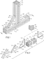
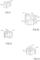
- some embodiments of the structural attachment system of the present disclosure comprise a hollow tube unit 10 comprising at least one T-slot 14 positioned between a pair of square slots 12 and a unit connector comprising a T-unit 30 sandwiched between a pair of composition units 18 and a pair of locking plates 16, such that the unit connector comprises, in order, a first locking plate 16, a first composition unit 18, the T-unit 30, a second composition unit 18, and a second locking plate 16, as shown in Figs.
- the T-unit 30 comprises a unit T-tab 32 configured to engage with the T-slot 14 on the hollow tube unit 10 an the locking plates 16 are configured to engage with the square slots 12, resulting in the unit connector being securely fastened to the hollow tube unit 10.
- the unit connector may be substantially triangular in shape with a right angle to create a 90 degree angle between two hollow tub units 10, wherein the T-unit 30 comprises a first unit T-tab 32 configured to engage with the T-slot 14 on a first hollow tube unit 10 and a second unit T-tab 32 configured to engage with the T-slot 14 on a second hollow tune unit 10.
- the unit connector may be other shapes to connect adjacent hollow tube units 10 at varying angles.
- the T-unit 30 may be a singular piece wherein two edges of the T-unit comprise T-tabs 32.
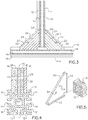
- the T-unit may comprise a plurality of T-unit pieces 20, which together form the desired shape T-unit.
- the T-unit may comprise a pair of T-unit pieces 20, each T-unit piece comprising a T-tab 22 configured to engage with a T-slot 14 on a hollow tube unit 10.
- the unit connectors may also comprise at least one fastener orifice, such as a pair of fastener orifices, extending therethrough, the at least one fastener orifice being configured to engage with a fastener to help secure the unit connector in place, locking the hollow tube units 10 in their desired configurations.
- the locking plate 16 may comprise a locking plate fastener orifice 28
- the composition unit 18 may comprise a composition unit fastener orifice 26
- the T-unit 30, 20 may comprise a T-unit fastener orifice 34, 24, wherein the orifices are all concentrically aligned, creating the fastener orifice in the unit connector.
- the unit connector may exist in alternative shapes, depending on the orientation of two hollow tube units 10 to be connected.
- the unit connector may comprise an interlocking double T unit 36 comprise a pair of interlocking T-tabs 38, wherein each of the T-tabs 38 is configured to engage with a T-slot 14 on a hollow tube unit 10.
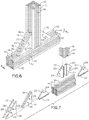
- the unit connector may comprise a corner connecting unit 40 comprising a pair of corner unit T-tabs 42 positioned at approximately a 90 degree angle relative to one another and a pair of panel slots 44, wherein the panel slots 44 are configured to accommodate a panel, such as a straight paneling unit 78, a curved corner paneling unit 80, a straight corner paneling unit 84, or the like, as shown in Figs. 15-17 .
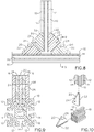
- a snap in holding unit 46, shown in Fig. 13 engaged with a locking unit 50, shown in Fig. 14 , may help secure adjacent paneling units to one another, as shown in Figs. 15-17 .
- the snap in holding unit 46 may comprise a pair of prongs 48 configured to engage with a locking unit slot 54 on the locking unit 50.
- the locking unit 50 may also comprise a locking unit T-tab 52 configured to engage with a T-slot 14 on a hollow tube unit 10. Paneling may be configured to engage with a space created by the engagement of the snap in holding unit 46 and the locking unit 50.
- hollow tube units 10 may be configured to engage with one another and also with corner connecting units 40, snap in holding units 46, and locking units 50 to attach a plurality of panels to one another, creating walls wherein, wherein the walls may comprise, for example, a plurality of straight paneling units 78, curved corner paneling units 80, straight corner paneling units 84, or the like with a material barrier/insulation 82 sandwiched between a pair of panels.
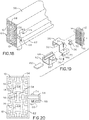
- FIGs. 18-20 illustrate an alternative embodiments wherein adjacent hollow tube units 10 may be attached by connecting a first sliding clamp unit 56 to a second sliding clamp unit 62 using a fastener, such as a bolt 74 and nut 76, which passes through a first clamp hole 70 and a second clamp hole 72 to attach the two sliding clamp units 56, 62 together.
- a fastener such as a bolt 74 and nut 76
- the first sliding clamp unit 56 may comprise a first clamp T-tab 58 configured to engage with a T-slot 14 in the first hollow tube unit 10 and the second sliding clamp unit 62 may comprise a second clamp T-tab 64 configured to engage with a T-slot 14 in the second hollow tube unit 10, wherein each of the sliding clamp units 56, 62 wrap partially around the circumference of its respective hollow tube unit 10 and meet at a side of the hollow tube units 10 that is opposite the first and second clamp T-tabs 58, 64, engaging with one another via a first clamp slot 60 engaging with a second clamp tab 66, wherein a clamp composition unit 68 may be positioned in the open space between the two sliding clamp units 56, 62.
- the hollow tube unit 10 may have a substantially square-shaped cross section with, for example, four sides comprising T-slots 14 and square slots 12.
- the hollow tub unit 10 may have any desired cross-sectional shape, such as a triangle, a pentagon, hexagon, heptagon, octagon, or the like, wherein each side may comprise the T-slots 14 and square slots 12.
- the structural attachment system may be made of any desired materials and, in some embodiments, is made of a metal, plastic, or other construction material suitable to provide structural integrity as required to meet national and international building code requirements.
- a user may attach a first hollow unit tube 10 to a second hollow unit tube 10 using a sliding connecting unit, which includes a locking plate 16 to prevent the hollow unit tubes 10 from sliding relative to one another.
- the user may then connect paneling units to the hollow unit tubes 10 by using, for example, a snap in holding unit 46 ad a locking unit 50, creating a structure with a wall, roof, and floor in an efficient manner
- Embodiments of the disclosed invention can be useful for easily and quickly erecting a structure.
Landscapes
- Engineering & Computer Science (AREA)
- Architecture (AREA)
- General Engineering & Computer Science (AREA)
- Civil Engineering (AREA)
- Structural Engineering (AREA)
- Physics & Mathematics (AREA)
- Electromagnetism (AREA)
- Mechanical Engineering (AREA)
- Joining Of Building Structures In Genera (AREA)
- Mutual Connection Of Rods And Tubes (AREA)
Claims (7)
- Système d'attachement structurel pour l'érection facile et rapide d'une structure, le système d'attachement structurel comprenant :une unité de tube creux (10) comprenant au moins une fente en forme de T (14) positionnée entre une paire de rainures carrée (12) ; etun connecteur d'unité comprenant dans l'ordre, une première plaque de verrouillage (16), une première unité de composition (18), une unité en forme de T (30), une deuxième unité de composition (18) et une deuxième plaque de verrouillage (16), l'unité en forme de T étant prise en sandwich entre la paire d'unités de composition, qui sont elles-mêmes prises en sandwich entre la paire de plaques de verrouillage,dans lequel :l'unité en forme de T (30) comprend une première patte d'unité en forme de T (32) configurée pour s'engager dans la fente en forme de T (14) sur l'unité de tube creux (10) ;les plaques de verrouillage (16) sont configurées pour s'engager dans les fentes carrées (12), ce qui a pour conséquence que le connecteur d'unité est fixé de manière coulissante à l'unité de tube creux (10) ; etdans lequel :le connecteur d'unité comprend au moins un orifice de fixation s'étendant à travers les plaques de verrouillage (16), les unités de composition (18) et l'unité en forme de T (30) ; etl'orifice de fixation est configuré pour recevoir un fixateur, qui est configuré pour sécuriser ensemble les plaques de verrouillage (16), les unités de composition (18), et l'unité en forme de T (30).
- Système de fixation structurel selon la revendication 1, comprenant en outre une deuxième unité de tube creux (10) comprenant au moins une fente en forme de T (14) positionné entre une paire de fentes carrées (12), la seconde unité de tube creux (10) étant configurée pour s'engager dans une deuxième patte d'unité en forme de T (32) sur l'unité en forme de T (30) et avec les plaques de verrouillage (16), de sorte que le premier tube creux (10) est fixé à la deuxième unité de tube creux (10).
- Système de fixation structurel selon l'une quelconque des revendications précédentes, dans lequel l'unité en forme de T comprend une paire de pièces d'unité en forme de T (20) qui ensemble forment l'unité en forme de T.
- Système de fixation structurel selon l'une quelconque des revendications précédentes, comprenant en outre un panneau fixé à l'unité de tube creux (10), formant une partie d'une paroi.
- Système de fixation structurel selon la revendication 4, comprenant en outre :une unité de verrouillage (50) comprenant une fente d'unité de verrouillage (54) et une patte en forme de T d'unité de verrouillage (52), la patte en forme de T d'unité de verrouillage (52) étant configurée pour s'engager dans la fente en forme de T (14) sur l'unité de tube creux (10) ; etune unité de maintien par encliquetage (46) comprenant une paire de broches (48) configurées pour s'engager dans la fente de l'unité de verrouillage (54) sur l'unité de verrouillage (50), dans lequel le panneau est configuré pour s'engager dans un espace créé par l'engagement de l'unité de maintien par encliquetage (46) et l'unité de verrouillage (50).
- Système de fixation structurel selon la revendication 4 ou 5, comprenant en outre :une unité de connexion de coins (40) comprenant une paire de pattes en forme de T d'unité de coin (42) et une paire de fentes de panneau (44),dans lequel les fentes de panneau (44) sont configurées pour recevoir un panneau.
- Système de fixation structurel selon la revendication 6, dans lequel le panneau comprend au moins un membre sélectionné dans le groupe constitué d'une unité de lambris droit (78), une unité de lambris à coins recourbés (80), et une unité de lambris à coins droits (84).
Applications Claiming Priority (2)
| Application Number | Priority Date | Filing Date | Title |
|---|---|---|---|
| US201461939085P | 2014-02-12 | 2014-02-12 | |
| PCT/US2015/014914 WO2015123116A1 (fr) | 2014-02-12 | 2015-02-06 | Système de fixation structurel |
Publications (3)
| Publication Number | Publication Date |
|---|---|
| EP3105384A1 EP3105384A1 (fr) | 2016-12-21 |
| EP3105384A4 EP3105384A4 (fr) | 2017-09-27 |
| EP3105384B1 true EP3105384B1 (fr) | 2018-10-31 |
Family
ID=53774469
Family Applications (1)
| Application Number | Title | Priority Date | Filing Date |
|---|---|---|---|
| EP15748609.3A Not-in-force EP3105384B1 (fr) | 2014-02-12 | 2015-02-06 | Système de fixation structurel |
Country Status (10)
| Country | Link |
|---|---|
| US (1) | US9200443B2 (fr) |
| EP (1) | EP3105384B1 (fr) |
| CN (1) | CN105934553B (fr) |
| AP (1) | AP2016009304A0 (fr) |
| AU (1) | AU2015217431B2 (fr) |
| BR (1) | BR112016018373A2 (fr) |
| CA (1) | CA2937921C (fr) |
| EA (1) | EA031148B1 (fr) |
| MX (1) | MX2016010274A (fr) |
| WO (1) | WO2015123116A1 (fr) |
Families Citing this family (10)
| Publication number | Priority date | Publication date | Assignee | Title |
|---|---|---|---|---|
| EP2786026B1 (fr) * | 2011-11-30 | 2015-10-14 | Hartmut Flaig | Barre profilée, assemblage de profilés et procédé de fabrication d'un assemblage de profilés |
| US20140294498A1 (en) * | 2013-04-02 | 2014-10-02 | William Robert Logan | Furniture component joining system |
| US10501929B2 (en) | 2013-09-30 | 2019-12-10 | Drew P. HENRY | Hollow connector sleeve with interlocking components |
| US10180007B1 (en) | 2016-05-06 | 2019-01-15 | Patrick J. Santini | Tubular beam extension |
| US10662650B2 (en) * | 2017-10-31 | 2020-05-26 | Vention Inc. | T-slot extrusion structure |
| US11680418B2 (en) * | 2018-08-28 | 2023-06-20 | Dhs Fraco Llc | Assembly for erecting and dismantling a common tower adjacent a building structure and a method of erecting and dismantling the same |
| NO344783B1 (en) * | 2019-04-05 | 2020-04-27 | Vardalife As | Fixing device for beam profiles |
| DE102019115548A1 (de) * | 2019-05-07 | 2020-11-12 | Carl Zeiss Fixture Systems Gmbh | Profilstrang für die Errichtung von Trägervorrichtungen |
| WO2021019284A1 (fr) * | 2019-07-31 | 2021-02-04 | Cavity Sliders Limited | Support amélioré |
| US11713590B2 (en) * | 2020-06-22 | 2023-08-01 | Katherine F. Hanna | Fence devices |
Family Cites Families (49)
| Publication number | Priority date | Publication date | Assignee | Title |
|---|---|---|---|---|
| US1465443A (en) * | 1922-03-23 | 1923-08-21 | Franklin P Smith | Window guard |
| US2690073A (en) * | 1948-11-24 | 1954-09-28 | Libbey Owens Ford Glass Co | Door and toilet stall construction |
| US3263388A (en) * | 1963-12-18 | 1966-08-02 | Allen Z Bogert | Ceiling tile hanger installation |
| FR1435227A (fr) * | 1965-03-16 | 1966-04-15 | Dispositif d'assemblage et éléments pour l'exécution de panneaux, cloisons et constructions similaires | |
| US3925939A (en) * | 1970-01-02 | 1975-12-16 | Angeles Metal Trim Co | Support structure for shelving |
| US3841049A (en) * | 1972-01-03 | 1974-10-15 | G Boice | Glazing framing method in modular wall construction |
| US3800489A (en) * | 1972-01-03 | 1974-04-02 | Structural Syst Inc | Modular wall construction |
| US3837128A (en) * | 1972-10-24 | 1974-09-24 | Fleury T | Partitioning system |
| US3989399A (en) * | 1974-10-04 | 1976-11-02 | Slowbe Joseph A | Structural joint assembly |
| US4347015A (en) * | 1980-11-03 | 1982-08-31 | General Electric Company | Structural frame corner assembly for electrical switchboards and the like |
| US4677794A (en) * | 1982-08-25 | 1987-07-07 | Ivan Parron | Support assembly for a shelf or like structure |
| US4976757A (en) * | 1989-05-04 | 1990-12-11 | Comp-Aire Systems, Inc. | Filtration plenum module constructed for on-site assembly |
| CH681383A5 (fr) * | 1990-04-11 | 1993-03-15 | Alusuisse Lonza Services Ag | |
| US5077951A (en) * | 1990-10-31 | 1992-01-07 | Baker Metal Products, Inc. | Suspended ceiling system |
| US5279090A (en) * | 1991-03-18 | 1994-01-18 | Asahi Kogyosha Co., Ltd. | Ceiling-frame construction method and ceiling-frame structure for clean rooms |
| US5231908A (en) * | 1991-05-13 | 1993-08-03 | Alpha Industries, Inc. | Apparatus for mounting a shearing blade |
| US5263296A (en) * | 1991-07-17 | 1993-11-23 | Speral Aluminium Inc. | Modular scaffolding assembly |
| US5634300A (en) | 1994-03-10 | 1997-06-03 | Plascore Inc. | Wall system employing grooved posts, connector blocks and T-bolt receiving battens |
| US6141926A (en) * | 1995-10-26 | 2000-11-07 | Tetrad Marketing/Sales Ltd. | Panel construction and connection system |
| US6073405A (en) * | 1995-12-22 | 2000-06-13 | Icf Kaiser Engineers, Inc. | Fitting for effecting bolted connection between a beam and a column in a steel frame structure |
| DE29611887U1 (de) * | 1996-07-09 | 1996-09-05 | Bauer Profiltechnik Gmbh | Montageelement |
| DE19854076C1 (de) * | 1998-11-24 | 2000-04-13 | Daimler Chrysler Ag | Hohlprofil mit zumindest einem seitlich abstehenden Flansch und ein Verfahren zur Herstellung desselben |
| US6516583B1 (en) * | 1999-03-26 | 2003-02-11 | David L. Houghton | Gusset plate connections for structural braced systems |
| US6481177B1 (en) | 2000-10-27 | 2002-11-19 | 80/20, Inc. | Inside corner connector for structural framing members |
| US6591573B2 (en) * | 2001-07-12 | 2003-07-15 | David L. Houghton | Gusset plates connection of beam to column |
| US7260919B1 (en) * | 2002-04-16 | 2007-08-28 | Daw Technologies, Inc. | Sealable ceiling assembly |
| US7716884B2 (en) * | 2002-08-16 | 2010-05-18 | Tapco International Corporation | Shutter assembly |
| US6749155B2 (en) * | 2002-09-13 | 2004-06-15 | The Boeing Company | Composite assembly with integrated composite joints |
| US20040079038A1 (en) * | 2002-10-25 | 2004-04-29 | Crooker Robert H. | Curtain wall anchor |
| DE20300637U1 (de) * | 2003-01-15 | 2004-06-17 | Franz Viegener Ii Gmbh & Co. Kg | Verbinder für Profile und Verbindungsanordnung |
| US7293394B2 (en) * | 2003-04-08 | 2007-11-13 | Davis John D | Buckling opposing support for I-joist |
| CN2667037Y (zh) * | 2003-12-18 | 2004-12-29 | 刘西嘉 | 一种多方位型材联接器 |
| US7555873B2 (en) * | 2004-11-30 | 2009-07-07 | The Boeing Company | Self-locating feature for a pi-joint assembly |
| DE202005016947U1 (de) | 2005-10-27 | 2006-01-05 | Viega Gmbh & Co. Kg | Verbinder für rinnenförmige Profilstäbe und Verbindungsanordnung |
| DE102006045225B4 (de) * | 2006-09-26 | 2009-10-22 | Göpfert, Janine | Präsentationsanordnung |
| US8282307B1 (en) * | 2007-04-06 | 2012-10-09 | Audubon Block Company | Furniture joinery |
| US7677830B1 (en) * | 2007-04-06 | 2010-03-16 | Brown Michael T | Furniture joinery |
| US7886496B1 (en) * | 2007-08-20 | 2011-02-15 | Daw Technologies, Inc. | Extruded aluminum bottom-load ceiling |
| US8365476B2 (en) * | 2007-12-28 | 2013-02-05 | Seismic Structural Design Associates, Inc. | Braced frame force distribution connection |
| DE102008018422A1 (de) * | 2008-04-10 | 2009-10-15 | Leichtmetallbau Schletter Gmbh | Montagesystem für Ständer für Photovoltaik-Freiflächenanlagen |
| CN201221134Y (zh) * | 2008-07-08 | 2009-04-15 | 上海信安幕墙建筑装饰有限公司 | 建筑桁架连接构件 |
| CN201234753Y (zh) | 2008-07-22 | 2009-05-13 | 东莞市兄奕塑胶制品有限公司 | 一种橱柜地角卡板 |
| IT1398514B1 (it) * | 2009-06-15 | 2013-03-01 | Unifor Spa | Struttura di telaio modulare per parete mobile |
| US8365484B2 (en) * | 2009-12-11 | 2013-02-05 | The Foley Group, LLC | Connector system for securing an end portion of a steel structural member to a vertical cast concrete member |
| US8910455B2 (en) * | 2010-03-19 | 2014-12-16 | Weihong Yang | Composite I-beam member |
| US8651393B2 (en) * | 2010-03-26 | 2014-02-18 | Holland, L.P. | Repair insert for repairing metallic structure |
| US9004715B1 (en) * | 2010-09-10 | 2015-04-14 | Emergency Technology, Inc. | Modular structural frame lighting |
| EP2786026B1 (fr) * | 2011-11-30 | 2015-10-14 | Hartmut Flaig | Barre profilée, assemblage de profilés et procédé de fabrication d'un assemblage de profilés |
| US9487949B2 (en) * | 2012-09-17 | 2016-11-08 | Steelcase Inc. | Method of positioning and installing a panel member on a floor-to-ceiling partition wall frame assembly |
-
2014
- 2014-12-19 US US14/578,118 patent/US9200443B2/en active Active
-
2015
- 2015-02-06 CA CA2937921A patent/CA2937921C/fr active Active
- 2015-02-06 AU AU2015217431A patent/AU2015217431B2/en not_active Ceased
- 2015-02-06 MX MX2016010274A patent/MX2016010274A/es unknown
- 2015-02-06 WO PCT/US2015/014914 patent/WO2015123116A1/fr active Application Filing
- 2015-02-06 EP EP15748609.3A patent/EP3105384B1/fr not_active Not-in-force
- 2015-02-06 AP AP2016009304A patent/AP2016009304A0/en unknown
- 2015-02-06 BR BR112016018373A patent/BR112016018373A2/pt not_active IP Right Cessation
- 2015-02-06 CN CN201580003973.3A patent/CN105934553B/zh not_active Expired - Fee Related
- 2015-02-06 EA EA201691480A patent/EA031148B1/ru not_active IP Right Cessation
Non-Patent Citations (1)
| Title |
|---|
| None * |
Also Published As
| Publication number | Publication date |
|---|---|
| AP2016009304A0 (en) | 2016-06-30 |
| BR112016018373A2 (pt) | 2018-09-18 |
| US20150225940A1 (en) | 2015-08-13 |
| US9200443B2 (en) | 2015-12-01 |
| AU2015217431B2 (en) | 2018-09-13 |
| EA031148B1 (ru) | 2018-11-30 |
| CA2937921C (fr) | 2018-08-21 |
| CA2937921A1 (fr) | 2015-08-20 |
| CN105934553B (zh) | 2018-01-09 |
| AU2015217431A1 (en) | 2016-07-14 |
| MX2016010274A (es) | 2017-04-13 |
| WO2015123116A1 (fr) | 2015-08-20 |
| EP3105384A1 (fr) | 2016-12-21 |
| CN105934553A (zh) | 2016-09-07 |
| EP3105384A4 (fr) | 2017-09-27 |
| EA201691480A1 (ru) | 2016-12-30 |
Similar Documents
| Publication | Publication Date | Title |
|---|---|---|
| EP3105384B1 (fr) | Système de fixation structurel | |
| US20140311082A1 (en) | Modular wall stud brace | |
| US7694483B1 (en) | Modular structure from prefabricated synthetic component elements | |
| US10081938B2 (en) | Modular construction system and method | |
| US20170145679A1 (en) | Connector system for c-channel members | |
| US8739493B2 (en) | Interlocking joint system for emergency structures | |
| JP2012241482A (ja) | 組立家屋及びその組立方法 | |
| CA3088705A1 (fr) | Abri construit a partir de panneaux d'interconnexion | |
| EP2960391A1 (fr) | Unite modulaire prefabriquee pour la construction de batiments | |
| US10900216B2 (en) | Supporting structure for a wall or roof partition | |
| US20050284061A1 (en) | Rigid foam building component | |
| JP6625988B2 (ja) | メタログ構造物用の補強材 | |
| JP2006316454A (ja) | 建築材料ユニット | |
| MX2013010418A (es) | Proteccion de pisos residenciales contra incendios durante 30 minutos. | |
| KR101242833B1 (ko) | 대리석 판넬 조립체 및 그 시공 방법 | |
| WO2015135054A1 (fr) | Entretoise de poteau mural modulaire | |
| OA18095A (en) | Structural attachment system | |
| US20160333567A1 (en) | Do-It-Yourself Construction of Resilient Houses in Disaster Prone Environments | |
| JP2008156836A (ja) | 耐震壁の構造および耐震補強工法 | |
| WO2011041824A1 (fr) | Ensemble ossature de bâtiment | |
| US20170284079A1 (en) | Self-interlocking blocks for habitable structures | |
| CA2953202A1 (fr) | Systeme de construction fonde sur les plaques de materiaux recycles | |
| US8261495B1 (en) | Connector system for connecting panels of framing members | |
| US20170081859A1 (en) | Slidable constructing plate | |
| JP2021038590A (ja) | 建材パネルおよびその建材パネルを用いて構築された構造体 |
Legal Events
| Date | Code | Title | Description |
|---|---|---|---|
| PUAI | Public reference made under article 153(3) epc to a published international application that has entered the european phase |
Free format text: ORIGINAL CODE: 0009012 |
|
| STAA | Information on the status of an ep patent application or granted ep patent |
Free format text: STATUS: REQUEST FOR EXAMINATION WAS MADE |
|
| 17P | Request for examination filed |
Effective date: 20160704 |
|
| AK | Designated contracting states |
Kind code of ref document: A1 Designated state(s): AL AT BE BG CH CY CZ DE DK EE ES FI FR GB GR HR HU IE IS IT LI LT LU LV MC MK MT NL NO PL PT RO RS SE SI SK SM TR |
|
| AX | Request for extension of the european patent |
Extension state: BA ME |
|
| DAX | Request for extension of the european patent (deleted) | ||
| A4 | Supplementary search report drawn up and despatched |
Effective date: 20170825 |
|
| RIC1 | Information provided on ipc code assigned before grant |
Ipc: E04B 1/58 20060101AFI20170821BHEP Ipc: F16B 7/04 20060101ALI20170821BHEP Ipc: F16B 7/00 20060101ALI20170821BHEP Ipc: E04B 2/78 20060101ALI20170821BHEP Ipc: E04B 2/60 20060101ALI20170821BHEP Ipc: E04B 1/24 20060101ALI20170821BHEP Ipc: E04B 1/38 20060101ALI20170821BHEP |
|
| GRAP | Despatch of communication of intention to grant a patent |
Free format text: ORIGINAL CODE: EPIDOSNIGR1 |
|
| STAA | Information on the status of an ep patent application or granted ep patent |
Free format text: STATUS: GRANT OF PATENT IS INTENDED |
|
| INTG | Intention to grant announced |
Effective date: 20180502 |
|
| GRAS | Grant fee paid |
Free format text: ORIGINAL CODE: EPIDOSNIGR3 |
|
| GRAA | (expected) grant |
Free format text: ORIGINAL CODE: 0009210 |
|
| STAA | Information on the status of an ep patent application or granted ep patent |
Free format text: STATUS: THE PATENT HAS BEEN GRANTED |
|
| AK | Designated contracting states |
Kind code of ref document: B1 Designated state(s): AL AT BE BG CH CY CZ DE DK EE ES FI FR GB GR HR HU IE IS IT LI LT LU LV MC MK MT NL NO PL PT RO RS SE SI SK SM TR |
|
| REG | Reference to a national code |
Ref country code: CH Ref legal event code: EP Ref country code: GB Ref legal event code: FG4D |
|
| REG | Reference to a national code |
Ref country code: AT Ref legal event code: REF Ref document number: 1059565 Country of ref document: AT Kind code of ref document: T Effective date: 20181115 |
|
| REG | Reference to a national code |
Ref country code: DE Ref legal event code: R096 Ref document number: 602015019138 Country of ref document: DE |
|
| REG | Reference to a national code |
Ref country code: IE Ref legal event code: FG4D |
|
| REG | Reference to a national code |
Ref country code: NL Ref legal event code: MP Effective date: 20181031 |
|
| REG | Reference to a national code |
Ref country code: LT Ref legal event code: MG4D |
|
| REG | Reference to a national code |
Ref country code: AT Ref legal event code: MK05 Ref document number: 1059565 Country of ref document: AT Kind code of ref document: T Effective date: 20181031 |
|
| PG25 | Lapsed in a contracting state [announced via postgrant information from national office to epo] |
Ref country code: HR Free format text: LAPSE BECAUSE OF FAILURE TO SUBMIT A TRANSLATION OF THE DESCRIPTION OR TO PAY THE FEE WITHIN THE PRESCRIBED TIME-LIMIT Effective date: 20181031 Ref country code: AT Free format text: LAPSE BECAUSE OF FAILURE TO SUBMIT A TRANSLATION OF THE DESCRIPTION OR TO PAY THE FEE WITHIN THE PRESCRIBED TIME-LIMIT Effective date: 20181031 Ref country code: LT Free format text: LAPSE BECAUSE OF FAILURE TO SUBMIT A TRANSLATION OF THE DESCRIPTION OR TO PAY THE FEE WITHIN THE PRESCRIBED TIME-LIMIT Effective date: 20181031 Ref country code: PL Free format text: LAPSE BECAUSE OF FAILURE TO SUBMIT A TRANSLATION OF THE DESCRIPTION OR TO PAY THE FEE WITHIN THE PRESCRIBED TIME-LIMIT Effective date: 20181031 Ref country code: IS Free format text: LAPSE BECAUSE OF FAILURE TO SUBMIT A TRANSLATION OF THE DESCRIPTION OR TO PAY THE FEE WITHIN THE PRESCRIBED TIME-LIMIT Effective date: 20190228 Ref country code: BG Free format text: LAPSE BECAUSE OF FAILURE TO SUBMIT A TRANSLATION OF THE DESCRIPTION OR TO PAY THE FEE WITHIN THE PRESCRIBED TIME-LIMIT Effective date: 20190131 Ref country code: FI Free format text: LAPSE BECAUSE OF FAILURE TO SUBMIT A TRANSLATION OF THE DESCRIPTION OR TO PAY THE FEE WITHIN THE PRESCRIBED TIME-LIMIT Effective date: 20181031 Ref country code: LV Free format text: LAPSE BECAUSE OF FAILURE TO SUBMIT A TRANSLATION OF THE DESCRIPTION OR TO PAY THE FEE WITHIN THE PRESCRIBED TIME-LIMIT Effective date: 20181031 Ref country code: ES Free format text: LAPSE BECAUSE OF FAILURE TO SUBMIT A TRANSLATION OF THE DESCRIPTION OR TO PAY THE FEE WITHIN THE PRESCRIBED TIME-LIMIT Effective date: 20181031 Ref country code: NO Free format text: LAPSE BECAUSE OF FAILURE TO SUBMIT A TRANSLATION OF THE DESCRIPTION OR TO PAY THE FEE WITHIN THE PRESCRIBED TIME-LIMIT Effective date: 20190131 |
|
| PG25 | Lapsed in a contracting state [announced via postgrant information from national office to epo] |
Ref country code: PT Free format text: LAPSE BECAUSE OF FAILURE TO SUBMIT A TRANSLATION OF THE DESCRIPTION OR TO PAY THE FEE WITHIN THE PRESCRIBED TIME-LIMIT Effective date: 20190301 Ref country code: RS Free format text: LAPSE BECAUSE OF FAILURE TO SUBMIT A TRANSLATION OF THE DESCRIPTION OR TO PAY THE FEE WITHIN THE PRESCRIBED TIME-LIMIT Effective date: 20181031 Ref country code: NL Free format text: LAPSE BECAUSE OF FAILURE TO SUBMIT A TRANSLATION OF THE DESCRIPTION OR TO PAY THE FEE WITHIN THE PRESCRIBED TIME-LIMIT Effective date: 20181031 Ref country code: AL Free format text: LAPSE BECAUSE OF FAILURE TO SUBMIT A TRANSLATION OF THE DESCRIPTION OR TO PAY THE FEE WITHIN THE PRESCRIBED TIME-LIMIT Effective date: 20181031 Ref country code: GR Free format text: LAPSE BECAUSE OF FAILURE TO SUBMIT A TRANSLATION OF THE DESCRIPTION OR TO PAY THE FEE WITHIN THE PRESCRIBED TIME-LIMIT Effective date: 20190201 Ref country code: SE Free format text: LAPSE BECAUSE OF FAILURE TO SUBMIT A TRANSLATION OF THE DESCRIPTION OR TO PAY THE FEE WITHIN THE PRESCRIBED TIME-LIMIT Effective date: 20181031 |
|
| PG25 | Lapsed in a contracting state [announced via postgrant information from national office to epo] |
Ref country code: DK Free format text: LAPSE BECAUSE OF FAILURE TO SUBMIT A TRANSLATION OF THE DESCRIPTION OR TO PAY THE FEE WITHIN THE PRESCRIBED TIME-LIMIT Effective date: 20181031 Ref country code: CZ Free format text: LAPSE BECAUSE OF FAILURE TO SUBMIT A TRANSLATION OF THE DESCRIPTION OR TO PAY THE FEE WITHIN THE PRESCRIBED TIME-LIMIT Effective date: 20181031 Ref country code: IT Free format text: LAPSE BECAUSE OF FAILURE TO SUBMIT A TRANSLATION OF THE DESCRIPTION OR TO PAY THE FEE WITHIN THE PRESCRIBED TIME-LIMIT Effective date: 20181031 |
|
| REG | Reference to a national code |
Ref country code: DE Ref legal event code: R097 Ref document number: 602015019138 Country of ref document: DE |
|
| PG25 | Lapsed in a contracting state [announced via postgrant information from national office to epo] |
Ref country code: SK Free format text: LAPSE BECAUSE OF FAILURE TO SUBMIT A TRANSLATION OF THE DESCRIPTION OR TO PAY THE FEE WITHIN THE PRESCRIBED TIME-LIMIT Effective date: 20181031 Ref country code: EE Free format text: LAPSE BECAUSE OF FAILURE TO SUBMIT A TRANSLATION OF THE DESCRIPTION OR TO PAY THE FEE WITHIN THE PRESCRIBED TIME-LIMIT Effective date: 20181031 Ref country code: SM Free format text: LAPSE BECAUSE OF FAILURE TO SUBMIT A TRANSLATION OF THE DESCRIPTION OR TO PAY THE FEE WITHIN THE PRESCRIBED TIME-LIMIT Effective date: 20181031 Ref country code: RO Free format text: LAPSE BECAUSE OF FAILURE TO SUBMIT A TRANSLATION OF THE DESCRIPTION OR TO PAY THE FEE WITHIN THE PRESCRIBED TIME-LIMIT Effective date: 20181031 |
|
| REG | Reference to a national code |
Ref country code: DE Ref legal event code: R119 Ref document number: 602015019138 Country of ref document: DE |
|
| PLBE | No opposition filed within time limit |
Free format text: ORIGINAL CODE: 0009261 |
|
| STAA | Information on the status of an ep patent application or granted ep patent |
Free format text: STATUS: NO OPPOSITION FILED WITHIN TIME LIMIT |
|
| REG | Reference to a national code |
Ref country code: CH Ref legal event code: PL |
|
| 26N | No opposition filed |
Effective date: 20190801 |
|
| GBPC | Gb: european patent ceased through non-payment of renewal fee |
Effective date: 20190206 |
|
| PG25 | Lapsed in a contracting state [announced via postgrant information from national office to epo] |
Ref country code: LU Free format text: LAPSE BECAUSE OF NON-PAYMENT OF DUE FEES Effective date: 20190206 Ref country code: MC Free format text: LAPSE BECAUSE OF FAILURE TO SUBMIT A TRANSLATION OF THE DESCRIPTION OR TO PAY THE FEE WITHIN THE PRESCRIBED TIME-LIMIT Effective date: 20181031 Ref country code: SI Free format text: LAPSE BECAUSE OF FAILURE TO SUBMIT A TRANSLATION OF THE DESCRIPTION OR TO PAY THE FEE WITHIN THE PRESCRIBED TIME-LIMIT Effective date: 20181031 |
|
| REG | Reference to a national code |
Ref country code: BE Ref legal event code: MM Effective date: 20190228 |
|
| REG | Reference to a national code |
Ref country code: IE Ref legal event code: MM4A |
|
| PG25 | Lapsed in a contracting state [announced via postgrant information from national office to epo] |
Ref country code: LI Free format text: LAPSE BECAUSE OF NON-PAYMENT OF DUE FEES Effective date: 20190228 Ref country code: CH Free format text: LAPSE BECAUSE OF NON-PAYMENT OF DUE FEES Effective date: 20190228 |
|
| PG25 | Lapsed in a contracting state [announced via postgrant information from national office to epo] |
Ref country code: DE Free format text: LAPSE BECAUSE OF NON-PAYMENT OF DUE FEES Effective date: 20190903 Ref country code: IE Free format text: LAPSE BECAUSE OF NON-PAYMENT OF DUE FEES Effective date: 20190206 Ref country code: GB Free format text: LAPSE BECAUSE OF NON-PAYMENT OF DUE FEES Effective date: 20190206 |
|
| PG25 | Lapsed in a contracting state [announced via postgrant information from national office to epo] |
Ref country code: FR Free format text: LAPSE BECAUSE OF NON-PAYMENT OF DUE FEES Effective date: 20190228 Ref country code: BE Free format text: LAPSE BECAUSE OF NON-PAYMENT OF DUE FEES Effective date: 20190228 |
|
| PG25 | Lapsed in a contracting state [announced via postgrant information from national office to epo] |
Ref country code: TR Free format text: LAPSE BECAUSE OF FAILURE TO SUBMIT A TRANSLATION OF THE DESCRIPTION OR TO PAY THE FEE WITHIN THE PRESCRIBED TIME-LIMIT Effective date: 20181031 |
|
| PG25 | Lapsed in a contracting state [announced via postgrant information from national office to epo] |
Ref country code: MT Free format text: LAPSE BECAUSE OF NON-PAYMENT OF DUE FEES Effective date: 20190206 |
|
| PG25 | Lapsed in a contracting state [announced via postgrant information from national office to epo] |
Ref country code: CY Free format text: LAPSE BECAUSE OF FAILURE TO SUBMIT A TRANSLATION OF THE DESCRIPTION OR TO PAY THE FEE WITHIN THE PRESCRIBED TIME-LIMIT Effective date: 20181031 |
|
| PG25 | Lapsed in a contracting state [announced via postgrant information from national office to epo] |
Ref country code: HU Free format text: LAPSE BECAUSE OF FAILURE TO SUBMIT A TRANSLATION OF THE DESCRIPTION OR TO PAY THE FEE WITHIN THE PRESCRIBED TIME-LIMIT; INVALID AB INITIO Effective date: 20150206 |
|
| PG25 | Lapsed in a contracting state [announced via postgrant information from national office to epo] |
Ref country code: MK Free format text: LAPSE BECAUSE OF FAILURE TO SUBMIT A TRANSLATION OF THE DESCRIPTION OR TO PAY THE FEE WITHIN THE PRESCRIBED TIME-LIMIT Effective date: 20181031 |