EP3105186B1 - Vorrichtung zum dispergieren von stinkenden abgasemissionen an der quelle - Google Patents
Vorrichtung zum dispergieren von stinkenden abgasemissionen an der quelle Download PDFInfo
- Publication number
- EP3105186B1 EP3105186B1 EP15709747.8A EP15709747A EP3105186B1 EP 3105186 B1 EP3105186 B1 EP 3105186B1 EP 15709747 A EP15709747 A EP 15709747A EP 3105186 B1 EP3105186 B1 EP 3105186B1
- Authority
- EP
- European Patent Office
- Prior art keywords
- injectors
- odor
- source
- foul
- air
- Prior art date
- Legal status (The legal status is an assumption and is not a legal conclusion. Google has not performed a legal analysis and makes no representation as to the accuracy of the status listed.)
- Active
Links
Images

Classifications
-
- F—MECHANICAL ENGINEERING; LIGHTING; HEATING; WEAPONS; BLASTING
- F23—COMBUSTION APPARATUS; COMBUSTION PROCESSES
- F23L—SUPPLYING AIR OR NON-COMBUSTIBLE LIQUIDS OR GASES TO COMBUSTION APPARATUS IN GENERAL ; VALVES OR DAMPERS SPECIALLY ADAPTED FOR CONTROLLING AIR SUPPLY OR DRAUGHT IN COMBUSTION APPARATUS; INDUCING DRAUGHT IN COMBUSTION APPARATUS; TOPS FOR CHIMNEYS OR VENTILATING SHAFTS; TERMINALS FOR FLUES
- F23L17/00—Inducing draught; Tops for chimneys or ventilating shafts; Terminals for flues
- F23L17/16—Induction apparatus, e.g. steam jet, acting on combustion products beyond the fire
-
- A—HUMAN NECESSITIES
- A61—MEDICAL OR VETERINARY SCIENCE; HYGIENE
- A61L—METHODS OR APPARATUS FOR STERILISING MATERIALS OR OBJECTS IN GENERAL; DISINFECTION, STERILISATION OR DEODORISATION OF AIR; CHEMICAL ASPECTS OF BANDAGES, DRESSINGS, ABSORBENT PADS OR SURGICAL ARTICLES; MATERIALS FOR BANDAGES, DRESSINGS, ABSORBENT PADS OR SURGICAL ARTICLES
- A61L9/00—Disinfection, sterilisation or deodorisation of air
- A61L9/14—Disinfection, sterilisation or deodorisation of air using sprayed or atomised substances including air-liquid contact processes
-
- B—PERFORMING OPERATIONS; TRANSPORTING
- B01—PHYSICAL OR CHEMICAL PROCESSES OR APPARATUS IN GENERAL
- B01D—SEPARATION
- B01D53/00—Separation of gases or vapours; Recovering vapours of volatile solvents from gases; Chemical or biological purification of waste gases, e.g. engine exhaust gases, smoke, fumes, flue gases, aerosols
-
- B—PERFORMING OPERATIONS; TRANSPORTING
- B01—PHYSICAL OR CHEMICAL PROCESSES OR APPARATUS IN GENERAL
- B01F—MIXING, e.g. DISSOLVING, EMULSIFYING OR DISPERSING
- B01F23/00—Mixing according to the phases to be mixed, e.g. dispersing or emulsifying
- B01F23/20—Mixing gases with liquids
- B01F23/21—Mixing gases with liquids by introducing liquids into gaseous media
- B01F23/213—Mixing gases with liquids by introducing liquids into gaseous media by spraying or atomising of the liquids
- B01F23/2132—Mixing gases with liquids by introducing liquids into gaseous media by spraying or atomising of the liquids using nozzles
- B01F23/21321—High pressure atomization, i.e. the liquid is atomized and sprayed by a jet at high pressure
-
- B—PERFORMING OPERATIONS; TRANSPORTING
- B01—PHYSICAL OR CHEMICAL PROCESSES OR APPARATUS IN GENERAL
- B01F—MIXING, e.g. DISSOLVING, EMULSIFYING OR DISPERSING
- B01F25/00—Flow mixers; Mixers for falling materials, e.g. solid particles
- B01F25/30—Injector mixers
-
- B—PERFORMING OPERATIONS; TRANSPORTING
- B05—SPRAYING OR ATOMISING IN GENERAL; APPLYING FLUENT MATERIALS TO SURFACES, IN GENERAL
- B05B—SPRAYING APPARATUS; ATOMISING APPARATUS; NOZZLES
- B05B12/00—Arrangements for controlling delivery; Arrangements for controlling the spray area
- B05B12/16—Arrangements for controlling delivery; Arrangements for controlling the spray area for controlling the spray area
- B05B12/18—Arrangements for controlling delivery; Arrangements for controlling the spray area for controlling the spray area using fluids, e.g. gas streams
-
- A—HUMAN NECESSITIES
- A61—MEDICAL OR VETERINARY SCIENCE; HYGIENE
- A61L—METHODS OR APPARATUS FOR STERILISING MATERIALS OR OBJECTS IN GENERAL; DISINFECTION, STERILISATION OR DEODORISATION OF AIR; CHEMICAL ASPECTS OF BANDAGES, DRESSINGS, ABSORBENT PADS OR SURGICAL ARTICLES; MATERIALS FOR BANDAGES, DRESSINGS, ABSORBENT PADS OR SURGICAL ARTICLES
- A61L2209/00—Aspects relating to disinfection, sterilisation or deodorisation of air
- A61L2209/10—Apparatus features
- A61L2209/11—Apparatus for controlling air treatment
- A61L2209/111—Sensor means, e.g. motion, brightness, scent, contaminant sensors
-
- A—HUMAN NECESSITIES
- A61—MEDICAL OR VETERINARY SCIENCE; HYGIENE
- A61L—METHODS OR APPARATUS FOR STERILISING MATERIALS OR OBJECTS IN GENERAL; DISINFECTION, STERILISATION OR DEODORISATION OF AIR; CHEMICAL ASPECTS OF BANDAGES, DRESSINGS, ABSORBENT PADS OR SURGICAL ARTICLES; MATERIALS FOR BANDAGES, DRESSINGS, ABSORBENT PADS OR SURGICAL ARTICLES
- A61L2209/00—Aspects relating to disinfection, sterilisation or deodorisation of air
- A61L2209/20—Method-related aspects
- A61L2209/21—Use of chemical compounds for treating air or the like
-
- A—HUMAN NECESSITIES
- A61—MEDICAL OR VETERINARY SCIENCE; HYGIENE
- A61L—METHODS OR APPARATUS FOR STERILISING MATERIALS OR OBJECTS IN GENERAL; DISINFECTION, STERILISATION OR DEODORISATION OF AIR; CHEMICAL ASPECTS OF BANDAGES, DRESSINGS, ABSORBENT PADS OR SURGICAL ARTICLES; MATERIALS FOR BANDAGES, DRESSINGS, ABSORBENT PADS OR SURGICAL ARTICLES
- A61L9/00—Disinfection, sterilisation or deodorisation of air
-
- B—PERFORMING OPERATIONS; TRANSPORTING
- B01—PHYSICAL OR CHEMICAL PROCESSES OR APPARATUS IN GENERAL
- B01F—MIXING, e.g. DISSOLVING, EMULSIFYING OR DISPERSING
- B01F2101/00—Mixing characterised by the nature of the mixed materials or by the application field
- B01F2101/54—Mixing liquid fragrances with air
-
- B—PERFORMING OPERATIONS; TRANSPORTING
- B08—CLEANING
- B08B—CLEANING IN GENERAL; PREVENTION OF FOULING IN GENERAL
- B08B2215/00—Preventing escape of dirt or fumes from the area where they are produced; Collecting or removing dirt or fumes from that area
- B08B2215/003—Preventing escape of dirt or fumes from the area where they are produced; Collecting or removing dirt or fumes from that area with the assistance of blowing nozzles
-
- F—MECHANICAL ENGINEERING; LIGHTING; HEATING; WEAPONS; BLASTING
- F23—COMBUSTION APPARATUS; COMBUSTION PROCESSES
- F23J—REMOVAL OR TREATMENT OF COMBUSTION PRODUCTS OR COMBUSTION RESIDUES; FLUES
- F23J2215/00—Preventing emissions
-
- F—MECHANICAL ENGINEERING; LIGHTING; HEATING; WEAPONS; BLASTING
- F23—COMBUSTION APPARATUS; COMBUSTION PROCESSES
- F23L—SUPPLYING AIR OR NON-COMBUSTIBLE LIQUIDS OR GASES TO COMBUSTION APPARATUS IN GENERAL ; VALVES OR DAMPERS SPECIALLY ADAPTED FOR CONTROLLING AIR SUPPLY OR DRAUGHT IN COMBUSTION APPARATUS; INDUCING DRAUGHT IN COMBUSTION APPARATUS; TOPS FOR CHIMNEYS OR VENTILATING SHAFTS; TERMINALS FOR FLUES
- F23L2700/00—Installations for increasing draught in chimneys; Specific draught control devices for locomotives
- F23L2700/001—Installations for increasing draught in chimneys
-
- Y—GENERAL TAGGING OF NEW TECHNOLOGICAL DEVELOPMENTS; GENERAL TAGGING OF CROSS-SECTIONAL TECHNOLOGIES SPANNING OVER SEVERAL SECTIONS OF THE IPC; TECHNICAL SUBJECTS COVERED BY FORMER USPC CROSS-REFERENCE ART COLLECTIONS [XRACs] AND DIGESTS
- Y02—TECHNOLOGIES OR APPLICATIONS FOR MITIGATION OR ADAPTATION AGAINST CLIMATE CHANGE
- Y02W—CLIMATE CHANGE MITIGATION TECHNOLOGIES RELATED TO WASTEWATER TREATMENT OR WASTE MANAGEMENT
- Y02W10/00—Technologies for wastewater treatment
- Y02W10/30—Wastewater or sewage treatment systems using renewable energies
- Y02W10/33—Wastewater or sewage treatment systems using renewable energies using wind energy
Definitions
- the invention relates to a source dispersing device for emissions of foul-smelling gaseous effluents, diffusely released by sources located close to the ground, in particular by wastewater treatment basins or any other activity which gives off odors.
- the gaseous effluents can be dispersed at a certain height in the atmosphere by chimneys.
- the height of the chimneys varies according to the nature and the composition of the gases, the regulations in force and the results of the study of dispersion of gaseous, particulate and smelly pollutants.
- the dispersion of gases in the environment is improved by increasing the stack height.
- a turbulent and sustained wind regime has the effect of mixing the gases with the ambient air and thus promoting the dispersion of pollutants.
- EP 2161446 describes a wind turbine which promotes the dispersion of gas in the atmosphere near a sewage treatment plant and which comprises a vertical mast equipped with a rotor with blades, the mast thus being able to be used for the evacuation of gas.
- WO 2010/044 055 proposed to improve and promote the dispersion of gases by providing at least one air or auxiliary gas injector installed near the outlet of a chimney and directed upwards so as to disperse the gases.
- Emissions can be diffuse and come from, for example, large basins of wastewater treatment plants, landfill sites, organic waste storage areas, organic matter ripening areas and similar facilities. Such installations are not necessarily open-air, and can be covered at least in part, but the gaseous effluents are no longer channeled to an outlet, including a chimney. It is no longer possible or difficult and expensive to capture the source of foul smelling, and a means used to fight against odors is to mask these odors by diffusing "white" products whose objective is to reduce the odor olfactory impact, covering odors.
- Such a means has a very limited efficiency because it acts only locally in the area of diffusion masking products.
- the molecules used are not completely neutral for the environment.
- electrochemical sensors In order to objectively evaluate the ambient odor rate, electrochemical sensors have been developed. Such sensors are positioned in areas of human presence to continuously measure the concentration of the most odorous molecules such as H 2 S, NH 3 , mercaptan. These sensors make it possible to convert chemical measurements into odor units that refer to human odor perception, and to indicate the current nuisance factor.
- the device comprises odor detectors distributed around the periphery of an installation comprising at least one source of foul odors, these detectors being arranged to communicate the results of their measurements to a measurement acquisition unit connected to a control unit which, according to the measurement results, activates at least one fan to supply at least one suitable sector of injectors.
- odor detectors distributed around the periphery of an installation comprising at least one source of foul odors, these detectors being arranged to communicate the results of their measurements to a measurement acquisition unit connected to a control unit which, according to the measurement results, activates at least one fan to supply at least one suitable sector of injectors.
- the injectors are located at a height lower than that of the upper edge of the odor source, in particular at the edge of the odor emission zone, that is to say close to the upper edge of the odor source. source of odors.
- the device comprises at least three injector sectors installed on the periphery of one or each source of foul odors, each sector comprising at least one injector.
- Each angular sector and its injectors are powered by an air distribution manifold equipped with a motorized control valve, the ramp being connected to the discharge of a fan.
- the injectors are adjustable in orientation.
- the means for supplying the injectors and the control means may be provided to ensure a variable pressure depending on the atmospheric conditions and measurements of odor units.
- control unit is controlled by management and control software programmed to take into account the dispersion parameters and the measurements of odor units in real time.
- the control unit can be controlled by simulation software predictive of the natural dispersion of the odor plume, integrated for a preventive action of automatic control of the induction dispersion device.
- the device may include means for injecting "masking" products into the air that supplies the injectors.
- the feed means of the injectors comprise at least one adjustable speed fan, and at least one connecting line between the fan outlet and a feed ramp of the injector or injectors.
- the supply means of the injector or injectors are adjustable to allow to modulate the pressure and the flow of air or auxiliary gas sent to the injectors according to the prevailing atmospheric conditions, and the properties of the gas plume, the stopping the supply means being controlled when the natural dispersion is sufficient or the conditions for which the odor emissions are low.
- a pond 1 wastewater treatment according to the state of the art.
- Such a basin is generally circular, and its diameter can reach 30 m and more.
- Pond 1 emits plumes 2 of foul-smelling gaseous effluents.
- the volume of the plumes 2 depends essentially on the evaporation and therefore on the parameters constituted by the speed of the sweeping air on the surface of the basin, the ambient temperature, the hygrometry and the atmospheric pressure.
- the plumes 2 are pushed by the wind whose direction is shown schematically by an arrow 3 and can reach houses M, which are on the side of the pelvis opposite the direction of the wind. Their inhabitants will thus be inconvenienced by the effluents released. This inconvenience will be even stronger in the case of folding winds, illustrated by the arrow 4 on Fig. 1 , towards the dwellings.
- a device D ( Fig.2 ) according to the invention comprises at least two injectors 5a, 5b of air, or auxiliary gas, oriented upwards and constituting inductors for dispersing the gaseous effluents.
- the injectors 5a, 5b are fed with air at medium pressure, in particular between 50 daPa and 300 daPa, by ramps 6a, 6b connected to the discharge of a non-visible fan on Fig.2 .
- the ramps or supply lines, such as 6a, 6b are advantageously made of spiral sheet or other lightweight material (especially textile).
- the injectors 5a, 5b are placed at the periphery of each source of odor emission, so as to ensure a rapid dispersion of odors by their dilution in the ambient air.
- the injectors 5a, 5b are located close to the ground, at a height close to the emission zone.
- the induction created by an upwardly directed jet of air 7 promotes the dynamic rise and dispersion of the smelly plume 2 when the effects of a falling wind are greater than those due to the difference in density between the gases and the air. 'ambiant air.
- the ramps 6a, 6b are separate feed means of the injectors. Thus, each injector 5a, 5b is fed by a separate supply means.
- the engine air distribution to the injectors 5a, 5b can thus be fractionated so as to select the injector or injectors to operate in the direction of the wind and the odor emission location. According to the scheme of Fig. 2 it is sufficient to operate the injector 5a located on the side of the basin 1 opposite the direction of the wind 3, to obtain a satisfactory effect.
- wind-sensitive control means B and different meteorological parameters are provided to supply the injector (s) whose position is most favorable to ensure the dispersion and recovery of the effluent plume. gaseous.
- control means B sensitive to the direction of the wind are arranged to select the operation of the injector (s) 5a, 5b whose situation, depending on the direction of the wind, is the most favorable to ensure dispersion and / or the rise of the plume of gaseous effluents.
- the pressure at the outlet of the air jets is variable and adjustable so as to continuously adapt the induction rate, or entrainment rate of the plume by the jet 7 directed upwards, with respect to the needs and in order to limit the energy consumption, essentially electrical, of the engine air supply device.
- This feed device comprises, for each odor source, at least one fan 8.1, 8.2, 8.3 ( Fig. 3 ) medium pressure, in particular from 50 daPa to 300daPa, variable speed, adjustable.
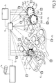
- Fig. 3 shows a plant 9 for wastewater treatment, equipped with devices according to the invention with several injectors 5a1 ... 5b3 installed on the periphery of odor emission zones consisting of basins 10, 11, and a zone 12 treatment tanks, or waste storage areas and maturing organic or other materials.
- the injectors 5a1, ... 5b3 are distributed in at least two sectors Sa1, Sb1 ... Sa3, Sb3 around the source.
- Each sector is independently supplied with pressurized air by a ramp whose flow rate is controlled by a damper or a motorized valve 13a1 ... 13b3 located on either side of an air injection from a fan 8.1 , 8.2, 8.3.
- each sector extends substantially along a semicircle and is respectively fed, via a register or an automated valve 13a1, 13b1, by a fan 8.1 whose discharge is connected to a portion of pipe between the valves 13a1 and 13b1 controlling the flow to the sectors Sa1, Sb1.
- Injectors 5a1, 5b1, represented in reduced numbers to simplify on Fig. 3 are preferably evenly distributed around the periphery of the odor source constituted by the pond 10.
- the distance between two adjacent injectors can be of the order of at least 1 m, and can reach 5 m and more depending on the perimeter to be treated.
- the wind direction detected by an air sleeve 14 and the wind force detected by an anemometer (not shown) are transmitted to a measurement acquisition unit B, and the pressurized air supply is directed towards the sector located on the side of the basin opposite to the direction of the wind.
- the number of injector sectors disposed at the periphery of a source may be greater than two in order to take better account of the direction of the wind and to limit the number of injectors per sector.
- each sector of injectors is powered separately.
- the upwardly directed air jets 7 allow the flow of foul gas to burst and quickly disperse the odor plume during periods of falling wind.
- the adjustment of the air pressure is ensured by a speed controller of the fan motor 8.1, 8.2, 8.3 concerned, or by any other mechanical means, in particular a register.
- the air pressure at the injectors is adjusted by the central B, generally between 50 daPa and 300daPa, depending on the atmospheric conditions, direction and intensity of the wind, pressure and external temperature.
- the injectors can be totally stopped when the weather conditions are favorable to the natural dispersion of the odors, in particular in high wind, or on the contrary by total calm with high atmospheric pressure.
- Odor sensors 15, in particular electrochemical, are distributed at an appropriate distance around the plant 9 to make a continuous measurement of the concentration of the most malodorous molecules, such as H 2 S, NH 3 , mercaptan.
- the results of the measurements thus carried out are transmitted to the central B of acquisition of the various parameters and meteorological measurements.
- the data collected by the central unit B is transmitted to a unit A constituted by a computer equipped with a program for managing and automatically controlling the various functions.
- a digital screen, not shown, indicates the displacement of the odor plume, measurements and dispersing equipment in action.
- the control unit B controls the actuators of the valves 13a1, 13b1 ... 13b3 to regulate their operation, particularly at the flow rate.
- the arrangement of the odor sensors 15 around the plant 9 makes it possible to act in real time and to modulate the operation of the dispersing device malodorous effluents by induction taking into account the meteorological conditions of the site: speed and direction of the wind, temperature and humidity of the air, atmospheric pressure.
- the measurements provided by the sensors 15 make it possible to correct the operating parameters and to check the efficiency of the device.
- control unit B keeps the fans 8.1, 8.2, 8.3 stopped and the valves 13a1, 13b1 ... 13a3 , 13b3 in the closed position.
- control unit B controls the starting of at least one of the fans 8.1, 8.2, 8.3, and opening the appropriate valve 13a1 ... 13b3, so that the appropriate injectors are operated.
- the sensors 15 make it possible to check whether the dispersion efficiency is sufficient for the odor level to drop below the determined threshold.
- the odor level can not be reduced to a value below the tolerable threshold, an operator will warn plant personnel and residents, or stop, as far as possible, sources of gaseous effluents malodorous.
- the device with air injectors according to the invention makes it possible to ensure two effects: a dilution of the plume of malodorous gaseous effluents and a rising effect of this plume.
- Masking products can be injected simultaneously into the air supplying the injectors 5a1 ... 5b3.
- Dispersion modeling software of the various sources of smelly gaseous effluents is advantageously installed in the unit A to allow to anticipate the intensity of formation of malodorous gaseous effluents, and the formation of plumes according to the meteorological conditions. It is then possible to act preventively by operating the sectors of appropriate injectors.
- the device according to the invention concerns not only open-air installations, but also installations of the semi-closed type, that is to say those which comprise a cover with outlet orifices devoid of high chimneys.
- These include greenhouses for sludge drying sewage treatment plants; such greenhouses have a roof in which openings are provided for the evacuation of the effluents.
- air injectors could be distributed around a greenhouse to disperse the effluents that escape through the openings of the roof.
- the invention has many advantages.
- the automatic control of the induction odor dispersion device controlled by the control system comprising the odor sensors 15, makes it possible to control and control the level of odor units at the periphery of the plant 9, and also to continuously optimize the operation of the device both preventively and in corrective action according to the different parameters measured.
- the energy consumption of the device is relatively low compared to the significant dilution effect with the ambient air.
- the device is automatically regulated to obtain the maximum dispersion effect while limiting its power consumption.
- the device is simple to implement and inexpensive with respect to an installation for the capture and biological chemical treatment of malodorous waste gases.
- the device can be installed on new or existing units.
Landscapes
- Engineering & Computer Science (AREA)
- Chemical & Material Sciences (AREA)
- Health & Medical Sciences (AREA)
- Chemical Kinetics & Catalysis (AREA)
- General Health & Medical Sciences (AREA)
- Public Health (AREA)
- Veterinary Medicine (AREA)
- Animal Behavior & Ethology (AREA)
- Life Sciences & Earth Sciences (AREA)
- Epidemiology (AREA)
- General Engineering & Computer Science (AREA)
- Mechanical Engineering (AREA)
- Combustion & Propulsion (AREA)
- Analytical Chemistry (AREA)
- General Chemical & Material Sciences (AREA)
- Oil, Petroleum & Natural Gas (AREA)
- Treating Waste Gases (AREA)
- Disinfection, Sterilisation Or Deodorisation Of Air (AREA)
Claims (12)
- Vorrichtung zum Dispergieren von übelriechenden Abgasemissionen an der Quelle, dadurch gekennzeichnet, dass sie aufweist:- ein Becken (1) als Quelle übelriechender Abgase,- mindestens zwei nach oben gerichtete Hilfsgas- oder Hilfsluftinjektoren (5a, 5b), welche am Umfang des die Quelle übelriechender Abgase bildenden Beckens (1) in gegenüberliegenden Zonen derart installiert sind, dass sie die übelriechenden Abgase verteilen,- Einrichtungen (6a, 6b) zur Versorgung der Injektoren, wobei jeder Injektor durch eine separate Versorgungseinrichtung versorgt wird,- und für die Windrichtung empfindliche Steuereinrichtungen, welche derart angeordnet sind, dass sie die Inbetriebnahme des Injektors oder der Injektoren wählen, dessen/deren Position entsprechend der Windrichtung die günstigste ist, um das Dispergieren und/oder das Aufsteigen der Abgaswolke zu gewährleisten.
- Vorrichtung nach Anspruch 1, dadurch gekennzeichnet, dass sie Geruchsdetektoren (15) aufweist, die am Umfang einer Anlage verteilt angeordnet sind, welche mindestens eine Quelle (10, 11, 12) übelriechender Gase aufweist, wobei diese Detektoren dazu angeordnet sind, um die Ergebnisse ihrer Messungen an eine Messungserfassungszentrale (B) zu übertragen, welche mit einer Steuereinheit (A) verbunden ist, welche, in Abhängigkeit von den Messergebnissen, mindestens ein Gebläse (8.1, 8.2, 8.3) aktiviert, um mindestens einen geeigneten Sektor (Sa1,...Sb3) von Injektoren zu versorgen.
- Vorrichtung nach Anspruch 1 oder 2, dadurch gekennzeichnet, dass die Injektoren (5a, 5b) sich nahe dem oberen Rand der Geruchsquelle befinden.
- Vorrichtung nach einem der vorhergehenden Ansprüche, dadurch gekennzeichnet, dass sie mindestens drei Injektorsektoren aufweist, die am Umfang einer oder jeder Quelle übelriechender Gerüche angeordnet sind, wobei jeder Sektor mindestens einen Injektor aufweist.
- Vorrichtung nach einem der vorhergehenden Ansprüche, dadurch gekennzeichnet, dass jeder Winkelsektor (Sa1,...Sb3) und dessen Injektoren über eine Luftverteilerrampe versorgt sind, welche mit einem motorisch betätigten Ventil (13a1,...13b3) versehen ist, wobei die Rampe mit dem Auslass eines Gebläses (8a1, 8a2, 8a3) verbunden ist.
- Vorrichtung nach einem der vorhergehenden Ansprüche, dadurch gekennzeichnet, dass die Injektoren (5a, 5b) in ihrer Ausrichtung verstellbar sind.
- Vorrichtung nach einem der vorhergehenden Ansprüche, dadurch gekennzeichnet, dass die Einrichtungen (6a, 6b) zur Versorgung der Injektoren und die Steuereinrichtungen vorgesehen sind, um in Abhängigkeit von den atmosphärischen Bedingungen und den Geruchseinheitenmessungen einen variablen Druck zu gewährleisten.
- Vorrichtung nach Anspruch 2, dadurch gekennzeichnet, dass die Steuereinheit (A) durch eine Verwaltungs- und Kontrollsoftware gesteuert ist, welche programmiert ist, um die Dispersionsparameter und die Geruchseinheitenmessungen in Echtzeit zu berücksichtigen.
- Vorrichtung nach Anspruch 2 oder 8, dadurch gekennzeichnet, dass die Steuereinheit (A) durch eine prädiktive Simulationssoftware der natürlichen Dispersion der Geruchswolke (2) gesteuert ist, wobei die Software für eine präventive Aktion der automatischen Steuerung der Dispersionsvorrichtung durch Induktion integriert ist.
- Vorrichtung nach einem der vorhergehenden Ansprüche, dadurch gekennzeichnet, dass sie eine Einrichtung zum Einblasen von "überdeckenden" Produkten in die Luft, welche die Injektoren speist, aufweist.
- Vorrichtung nach einem der vorhergehenden Ansprüche, dadurch gekennzeichnet, dass die Einrichtungen zur Versorgung der Injektoren mindestens ein Gebläse (8.1, 8.2, 8.3) mit regelbarer Drehzahl und mindestens eine Verbindungsleitung zwischen dem Auslass des Gebläses und einer Rampe zur Versorgung des Injektors oder der Injektoren aufweist.
- Vorrichtung nach Anspruch 11, dadurch gekennzeichnet, dass die Einrichtungen zur Versorgung des oder der Injektoren regelbar sind, um das Modulieren des Drucks und der an die Injektoren gelieferte Fördermenge an Luft oder Hilfsgas gemäß den momentanen atmosphärischen Bedingungen und den Eigenschaften der Gaswolke zu ermöglichen, wobei das Anhalten der Versorgungseinrichtungen gesteuert wird, wenn die natürliche Dispersion ausreichend ist.
Priority Applications (1)
| Application Number | Priority Date | Filing Date | Title |
|---|---|---|---|
| PL15709747T PL3105186T3 (pl) | 2014-02-14 | 2015-02-12 | Urządzenie do rozpraszania u źródła emisji wyziewów gazowych powodujących mdłości |
Applications Claiming Priority (2)
| Application Number | Priority Date | Filing Date | Title |
|---|---|---|---|
| FR1451164A FR3017545A1 (fr) | 2014-02-14 | 2014-02-14 | Dispositif pour disperser a la source les emissions d'effluents gazeux nauseabonds |
| PCT/IB2015/051052 WO2015121820A1 (fr) | 2014-02-14 | 2015-02-12 | Dispositif pour disperser a la source les emissions d'effluents gazeux nauseabonds |
Publications (2)
| Publication Number | Publication Date |
|---|---|
| EP3105186A1 EP3105186A1 (de) | 2016-12-21 |
| EP3105186B1 true EP3105186B1 (de) | 2018-04-04 |
Family
ID=50729650
Family Applications (1)
| Application Number | Title | Priority Date | Filing Date |
|---|---|---|---|
| EP15709747.8A Active EP3105186B1 (de) | 2014-02-14 | 2015-02-12 | Vorrichtung zum dispergieren von stinkenden abgasemissionen an der quelle |
Country Status (8)
| Country | Link |
|---|---|
| US (1) | US10092671B2 (de) |
| EP (1) | EP3105186B1 (de) |
| CN (1) | CN106132509B (de) |
| AU (1) | AU2015216615B2 (de) |
| ES (1) | ES2675021T3 (de) |
| FR (1) | FR3017545A1 (de) |
| PL (1) | PL3105186T3 (de) |
| WO (1) | WO2015121820A1 (de) |
Families Citing this family (12)
| Publication number | Priority date | Publication date | Assignee | Title |
|---|---|---|---|---|
| US12269315B2 (en) | 2020-08-20 | 2025-04-08 | Denso International America, Inc. | Systems and methods for measuring and managing odor brought into rental vehicles |
| US11813926B2 (en) | 2020-08-20 | 2023-11-14 | Denso International America, Inc. | Binding agent and olfaction sensor |
| US12251991B2 (en) | 2020-08-20 | 2025-03-18 | Denso International America, Inc. | Humidity control for olfaction sensors |
| US12017506B2 (en) | 2020-08-20 | 2024-06-25 | Denso International America, Inc. | Passenger cabin air control systems and methods |
| US11636870B2 (en) | 2020-08-20 | 2023-04-25 | Denso International America, Inc. | Smoking cessation systems and methods |
| US12377711B2 (en) | 2020-08-20 | 2025-08-05 | Denso International America, Inc. | Vehicle feature control systems and methods based on smoking |
| US11760169B2 (en) | 2020-08-20 | 2023-09-19 | Denso International America, Inc. | Particulate control systems and methods for olfaction sensors |
| US11881093B2 (en) | 2020-08-20 | 2024-01-23 | Denso International America, Inc. | Systems and methods for identifying smoking in vehicles |
| US11760170B2 (en) | 2020-08-20 | 2023-09-19 | Denso International America, Inc. | Olfaction sensor preservation systems and methods |
| US11828210B2 (en) | 2020-08-20 | 2023-11-28 | Denso International America, Inc. | Diagnostic systems and methods of vehicles using olfaction |
| US11932080B2 (en) | 2020-08-20 | 2024-03-19 | Denso International America, Inc. | Diagnostic and recirculation control systems and methods |
| CN119655152B (zh) * | 2024-12-25 | 2025-07-22 | 天津商业大学 | 应用于农业自动化浇灌设备的监测运维系统 |
Family Cites Families (5)
| Publication number | Priority date | Publication date | Assignee | Title |
|---|---|---|---|---|
| US2544769A (en) * | 1945-12-29 | 1951-03-13 | Scovill Manufacturing Co | Fume and vapor control for cleansing tanks |
| FR2740862B1 (fr) * | 1995-11-03 | 1998-01-23 | Amphoux Andre | Dispositif pour aspirer un fluide gazeux a travers un conduit pour le rejeter a l'exterieur de celui-ci |
| US5930994A (en) * | 1996-07-02 | 1999-08-03 | Ibiden Co., Ltd. | Reverse cleaning regeneration type exhaust emission control device and method of regenerating the same |
| FR2935762B1 (fr) * | 2008-09-09 | 2013-02-15 | Suez Environnement | Eolienne |
| FR2937120B1 (fr) * | 2008-10-14 | 2010-11-19 | Suez Environnement | Dispositif de dispersion de gaz sortant d'une cheminee |
-
2014
- 2014-02-14 FR FR1451164A patent/FR3017545A1/fr not_active Withdrawn
-
2015
- 2015-02-12 AU AU2015216615A patent/AU2015216615B2/en active Active
- 2015-02-12 ES ES15709747.8T patent/ES2675021T3/es active Active
- 2015-02-12 WO PCT/IB2015/051052 patent/WO2015121820A1/fr not_active Ceased
- 2015-02-12 CN CN201580015498.1A patent/CN106132509B/zh active Active
- 2015-02-12 US US15/118,007 patent/US10092671B2/en active Active
- 2015-02-12 PL PL15709747T patent/PL3105186T3/pl unknown
- 2015-02-12 EP EP15709747.8A patent/EP3105186B1/de active Active
Also Published As
| Publication number | Publication date |
|---|---|
| WO2015121820A1 (fr) | 2015-08-20 |
| FR3017545A1 (fr) | 2015-08-21 |
| CN106132509A (zh) | 2016-11-16 |
| AU2015216615B2 (en) | 2019-04-11 |
| EP3105186A1 (de) | 2016-12-21 |
| PL3105186T3 (pl) | 2019-03-29 |
| US20170007735A1 (en) | 2017-01-12 |
| ES2675021T3 (es) | 2018-07-05 |
| CN106132509B (zh) | 2019-04-23 |
| US10092671B2 (en) | 2018-10-09 |
| AU2015216615A1 (en) | 2016-09-01 |
Similar Documents
| Publication | Publication Date | Title |
|---|---|---|
| EP3105186A1 (de) | Vorrichtung zum dispergieren von stinkenden abgasemissionen an der quelle | |
| FR3043331B1 (fr) | Puits de carbone urbain | |
| KR101590621B1 (ko) | 복합 시설물 | |
| EP3574980B1 (de) | Schadstoffbeseitigendes bauwerk | |
| FR3076601A1 (fr) | Systeme de traitement de l'air pour un batiment ou navire | |
| FR3087136A1 (fr) | Procede et dispositif de gestion d'un dispositif de traitement de gaz vicie. | |
| WO2013029172A1 (fr) | Système et méthode pour contrôler et traiter des émanations gazeuses à l'intérieur d'un puits d'accès d'eaux usées | |
| KR100709605B1 (ko) | 축사 환기 공조 시스템 | |
| CN212260194U (zh) | 有机废弃物养殖装置及系统 | |
| CA2872937A1 (fr) | Dispositif et procede pour broyer et recuperer des dechets domestiques organiques | |
| JP6445663B1 (ja) | 生物脱臭装置 | |
| NL2025921B1 (en) | Plant-based air filtration device and its use | |
| PL197874B1 (pl) | Sposób obrabiania gazu nadającego się do utleniania, wytwarzanego z odpadków na wysypisku, oraz konstrukcja wysypiska | |
| KR101185382B1 (ko) | 블록형 관찰로 | |
| LT6501B (lt) | Nuotekų perpumpavimo stočių bei nuotekų valymo stočių dezinfekavimo sistema | |
| JP6445664B1 (ja) | 生物脱臭装置 | |
| FR2758099A1 (fr) | Dispositif pour le drainage des atmospheres urbaines polluees | |
| WO2010044055A1 (fr) | Dispositif de dispersion de gaz sortant d'une cheminée | |
| WO2024200572A1 (fr) | Système de filtration pour un bassin, bassin et procédé de filtration associés | |
| KR20210012575A (ko) | 침수방식을 이용한 화력발전소의 미세먼지 제거장치 | |
| KR200394513Y1 (ko) | 축사 환기 공조 시스템 | |
| MX2007010499A (es) | Metodo para colocar y operar un arreglo de ventilador dispersor de olor. | |
| CN121466754A (zh) | 一种基于气体分离膜的粪污暂存区臭气分离与智能控制方法 | |
| EP3365286A1 (de) | Sequenzieller biologischer reaktor und verfahren unter nutzung des reaktors | |
| JPH03154698A (ja) | 限定水域での溶存酸素量改良方法およびその装置ならびにこれを用いた魚巣構造体 |
Legal Events
| Date | Code | Title | Description |
|---|---|---|---|
| PUAI | Public reference made under article 153(3) epc to a published international application that has entered the european phase |
Free format text: ORIGINAL CODE: 0009012 |
|
| STAA | Information on the status of an ep patent application or granted ep patent |
Free format text: STATUS: REQUEST FOR EXAMINATION WAS MADE |
|
| 17P | Request for examination filed |
Effective date: 20160809 |
|
| AK | Designated contracting states |
Kind code of ref document: A1 Designated state(s): AL AT BE BG CH CY CZ DE DK EE ES FI FR GB GR HR HU IE IS IT LI LT LU LV MC MK MT NL NO PL PT RO RS SE SI SK SM TR |
|
| AX | Request for extension of the european patent |
Extension state: BA ME |
|
| RIN1 | Information on inventor provided before grant (corrected) |
Inventor name: KELLY, ROBERT Inventor name: DUONG, FREDERIC Inventor name: CHANTRE, PATRICK |
|
| DAX | Request for extension of the european patent (deleted) | ||
| REG | Reference to a national code |
Ref country code: DE Ref legal event code: R079 Ref document number: 602015009572 Country of ref document: DE Free format text: PREVIOUS MAIN CLASS: C02F0001000000 Ipc: B05B0015040000 |
|
| GRAP | Despatch of communication of intention to grant a patent |
Free format text: ORIGINAL CODE: EPIDOSNIGR1 |
|
| RIC1 | Information provided on ipc code assigned before grant |
Ipc: F23L 17/16 20060101ALI20170913BHEP Ipc: A61L 9/00 20060101ALN20170913BHEP Ipc: B05B 15/04 20060101AFI20170913BHEP |
|
| STAA | Information on the status of an ep patent application or granted ep patent |
Free format text: STATUS: GRANT OF PATENT IS INTENDED |
|
| RIC1 | Information provided on ipc code assigned before grant |
Ipc: F23L 17/16 20060101ALI20170915BHEP Ipc: A61L 9/00 20060101ALN20170915BHEP Ipc: B05B 15/04 20060101AFI20170915BHEP |
|
| INTG | Intention to grant announced |
Effective date: 20171019 |
|
| GRAS | Grant fee paid |
Free format text: ORIGINAL CODE: EPIDOSNIGR3 |
|
| GRAA | (expected) grant |
Free format text: ORIGINAL CODE: 0009210 |
|
| STAA | Information on the status of an ep patent application or granted ep patent |
Free format text: STATUS: THE PATENT HAS BEEN GRANTED |
|
| AK | Designated contracting states |
Kind code of ref document: B1 Designated state(s): AL AT BE BG CH CY CZ DE DK EE ES FI FR GB GR HR HU IE IS IT LI LT LU LV MC MK MT NL NO PL PT RO RS SE SI SK SM TR |
|
| REG | Reference to a national code |
Ref country code: GB Ref legal event code: FG4D Free format text: NOT ENGLISH |
|
| REG | Reference to a national code |
Ref country code: CH Ref legal event code: EP |
|
| REG | Reference to a national code |
Ref country code: AT Ref legal event code: REF Ref document number: 985030 Country of ref document: AT Kind code of ref document: T Effective date: 20180415 |
|
| REG | Reference to a national code |
Ref country code: IE Ref legal event code: FG4D Free format text: LANGUAGE OF EP DOCUMENT: FRENCH |
|
| REG | Reference to a national code |
Ref country code: DE Ref legal event code: R096 Ref document number: 602015009572 Country of ref document: DE |
|
| REG | Reference to a national code |
Ref country code: ES Ref legal event code: FG2A Ref document number: 2675021 Country of ref document: ES Kind code of ref document: T3 Effective date: 20180705 |
|
| REG | Reference to a national code |
Ref country code: NL Ref legal event code: FP |
|
| REG | Reference to a national code |
Ref country code: LT Ref legal event code: MG4D |
|
| PG25 | Lapsed in a contracting state [announced via postgrant information from national office to epo] |
Ref country code: AL Free format text: LAPSE BECAUSE OF FAILURE TO SUBMIT A TRANSLATION OF THE DESCRIPTION OR TO PAY THE FEE WITHIN THE PRESCRIBED TIME-LIMIT Effective date: 20180404 Ref country code: BG Free format text: LAPSE BECAUSE OF FAILURE TO SUBMIT A TRANSLATION OF THE DESCRIPTION OR TO PAY THE FEE WITHIN THE PRESCRIBED TIME-LIMIT Effective date: 20180704 Ref country code: LT Free format text: LAPSE BECAUSE OF FAILURE TO SUBMIT A TRANSLATION OF THE DESCRIPTION OR TO PAY THE FEE WITHIN THE PRESCRIBED TIME-LIMIT Effective date: 20180404 Ref country code: FI Free format text: LAPSE BECAUSE OF FAILURE TO SUBMIT A TRANSLATION OF THE DESCRIPTION OR TO PAY THE FEE WITHIN THE PRESCRIBED TIME-LIMIT Effective date: 20180404 Ref country code: NO Free format text: LAPSE BECAUSE OF FAILURE TO SUBMIT A TRANSLATION OF THE DESCRIPTION OR TO PAY THE FEE WITHIN THE PRESCRIBED TIME-LIMIT Effective date: 20180704 Ref country code: SE Free format text: LAPSE BECAUSE OF FAILURE TO SUBMIT A TRANSLATION OF THE DESCRIPTION OR TO PAY THE FEE WITHIN THE PRESCRIBED TIME-LIMIT Effective date: 20180404 |
|
| PG25 | Lapsed in a contracting state [announced via postgrant information from national office to epo] |
Ref country code: RS Free format text: LAPSE BECAUSE OF FAILURE TO SUBMIT A TRANSLATION OF THE DESCRIPTION OR TO PAY THE FEE WITHIN THE PRESCRIBED TIME-LIMIT Effective date: 20180404 Ref country code: LV Free format text: LAPSE BECAUSE OF FAILURE TO SUBMIT A TRANSLATION OF THE DESCRIPTION OR TO PAY THE FEE WITHIN THE PRESCRIBED TIME-LIMIT Effective date: 20180404 Ref country code: HR Free format text: LAPSE BECAUSE OF FAILURE TO SUBMIT A TRANSLATION OF THE DESCRIPTION OR TO PAY THE FEE WITHIN THE PRESCRIBED TIME-LIMIT Effective date: 20180404 Ref country code: GR Free format text: LAPSE BECAUSE OF FAILURE TO SUBMIT A TRANSLATION OF THE DESCRIPTION OR TO PAY THE FEE WITHIN THE PRESCRIBED TIME-LIMIT Effective date: 20180705 |
|
| REG | Reference to a national code |
Ref country code: AT Ref legal event code: MK05 Ref document number: 985030 Country of ref document: AT Kind code of ref document: T Effective date: 20180404 |
|
| PG25 | Lapsed in a contracting state [announced via postgrant information from national office to epo] |
Ref country code: PT Free format text: LAPSE BECAUSE OF FAILURE TO SUBMIT A TRANSLATION OF THE DESCRIPTION OR TO PAY THE FEE WITHIN THE PRESCRIBED TIME-LIMIT Effective date: 20180806 |
|
| REG | Reference to a national code |
Ref country code: DE Ref legal event code: R097 Ref document number: 602015009572 Country of ref document: DE |
|
| PG25 | Lapsed in a contracting state [announced via postgrant information from national office to epo] |
Ref country code: SK Free format text: LAPSE BECAUSE OF FAILURE TO SUBMIT A TRANSLATION OF THE DESCRIPTION OR TO PAY THE FEE WITHIN THE PRESCRIBED TIME-LIMIT Effective date: 20180404 Ref country code: RO Free format text: LAPSE BECAUSE OF FAILURE TO SUBMIT A TRANSLATION OF THE DESCRIPTION OR TO PAY THE FEE WITHIN THE PRESCRIBED TIME-LIMIT Effective date: 20180404 Ref country code: CZ Free format text: LAPSE BECAUSE OF FAILURE TO SUBMIT A TRANSLATION OF THE DESCRIPTION OR TO PAY THE FEE WITHIN THE PRESCRIBED TIME-LIMIT Effective date: 20180404 Ref country code: AT Free format text: LAPSE BECAUSE OF FAILURE TO SUBMIT A TRANSLATION OF THE DESCRIPTION OR TO PAY THE FEE WITHIN THE PRESCRIBED TIME-LIMIT Effective date: 20180404 Ref country code: EE Free format text: LAPSE BECAUSE OF FAILURE TO SUBMIT A TRANSLATION OF THE DESCRIPTION OR TO PAY THE FEE WITHIN THE PRESCRIBED TIME-LIMIT Effective date: 20180404 Ref country code: DK Free format text: LAPSE BECAUSE OF FAILURE TO SUBMIT A TRANSLATION OF THE DESCRIPTION OR TO PAY THE FEE WITHIN THE PRESCRIBED TIME-LIMIT Effective date: 20180404 |
|
| REG | Reference to a national code |
Ref country code: CH Ref legal event code: PK Free format text: RECTIFICATIONS |
|
| PLBE | No opposition filed within time limit |
Free format text: ORIGINAL CODE: 0009261 |
|
| STAA | Information on the status of an ep patent application or granted ep patent |
Free format text: STATUS: NO OPPOSITION FILED WITHIN TIME LIMIT |
|
| RIC2 | Information provided on ipc code assigned after grant |
Ipc: A61L 9/00 20060101ALN20170915BHEP Ipc: B05B 15/04 20060101AFI20170915BHEP Ipc: F23L 17/16 20060101ALI20170915BHEP |
|
| PG25 | Lapsed in a contracting state [announced via postgrant information from national office to epo] |
Ref country code: SM Free format text: LAPSE BECAUSE OF FAILURE TO SUBMIT A TRANSLATION OF THE DESCRIPTION OR TO PAY THE FEE WITHIN THE PRESCRIBED TIME-LIMIT Effective date: 20180404 Ref country code: IT Free format text: LAPSE BECAUSE OF FAILURE TO SUBMIT A TRANSLATION OF THE DESCRIPTION OR TO PAY THE FEE WITHIN THE PRESCRIBED TIME-LIMIT Effective date: 20180404 |
|
| 26N | No opposition filed |
Effective date: 20190107 |
|
| PG25 | Lapsed in a contracting state [announced via postgrant information from national office to epo] |
Ref country code: SI Free format text: LAPSE BECAUSE OF FAILURE TO SUBMIT A TRANSLATION OF THE DESCRIPTION OR TO PAY THE FEE WITHIN THE PRESCRIBED TIME-LIMIT Effective date: 20180404 |
|
| REG | Reference to a national code |
Ref country code: CH Ref legal event code: PL |
|
| PG25 | Lapsed in a contracting state [announced via postgrant information from national office to epo] |
Ref country code: LU Free format text: LAPSE BECAUSE OF NON-PAYMENT OF DUE FEES Effective date: 20190212 Ref country code: MC Free format text: LAPSE BECAUSE OF FAILURE TO SUBMIT A TRANSLATION OF THE DESCRIPTION OR TO PAY THE FEE WITHIN THE PRESCRIBED TIME-LIMIT Effective date: 20180404 |
|
| REG | Reference to a national code |
Ref country code: IE Ref legal event code: MM4A |
|
| PG25 | Lapsed in a contracting state [announced via postgrant information from national office to epo] |
Ref country code: LI Free format text: LAPSE BECAUSE OF NON-PAYMENT OF DUE FEES Effective date: 20190228 Ref country code: CH Free format text: LAPSE BECAUSE OF NON-PAYMENT OF DUE FEES Effective date: 20190228 |
|
| PG25 | Lapsed in a contracting state [announced via postgrant information from national office to epo] |
Ref country code: IE Free format text: LAPSE BECAUSE OF NON-PAYMENT OF DUE FEES Effective date: 20190212 |
|
| PG25 | Lapsed in a contracting state [announced via postgrant information from national office to epo] |
Ref country code: TR Free format text: LAPSE BECAUSE OF FAILURE TO SUBMIT A TRANSLATION OF THE DESCRIPTION OR TO PAY THE FEE WITHIN THE PRESCRIBED TIME-LIMIT Effective date: 20180404 |
|
| PG25 | Lapsed in a contracting state [announced via postgrant information from national office to epo] |
Ref country code: MT Free format text: LAPSE BECAUSE OF FAILURE TO SUBMIT A TRANSLATION OF THE DESCRIPTION OR TO PAY THE FEE WITHIN THE PRESCRIBED TIME-LIMIT Effective date: 20180404 |
|
| PG25 | Lapsed in a contracting state [announced via postgrant information from national office to epo] |
Ref country code: CY Free format text: LAPSE BECAUSE OF FAILURE TO SUBMIT A TRANSLATION OF THE DESCRIPTION OR TO PAY THE FEE WITHIN THE PRESCRIBED TIME-LIMIT Effective date: 20180404 |
|
| PG25 | Lapsed in a contracting state [announced via postgrant information from national office to epo] |
Ref country code: IS Free format text: LAPSE BECAUSE OF FAILURE TO SUBMIT A TRANSLATION OF THE DESCRIPTION OR TO PAY THE FEE WITHIN THE PRESCRIBED TIME-LIMIT Effective date: 20180804 |
|
| PG25 | Lapsed in a contracting state [announced via postgrant information from national office to epo] |
Ref country code: HU Free format text: LAPSE BECAUSE OF FAILURE TO SUBMIT A TRANSLATION OF THE DESCRIPTION OR TO PAY THE FEE WITHIN THE PRESCRIBED TIME-LIMIT; INVALID AB INITIO Effective date: 20150212 |
|
| PG25 | Lapsed in a contracting state [announced via postgrant information from national office to epo] |
Ref country code: MK Free format text: LAPSE BECAUSE OF FAILURE TO SUBMIT A TRANSLATION OF THE DESCRIPTION OR TO PAY THE FEE WITHIN THE PRESCRIBED TIME-LIMIT Effective date: 20180404 |
|
| P01 | Opt-out of the competence of the unified patent court (upc) registered |
Effective date: 20230601 |
|
| REG | Reference to a national code |
Ref country code: NL Ref legal event code: PD Owner name: SUEZ INTERNATIONAL; FR Free format text: DETAILS ASSIGNMENT: CHANGE OF OWNER(S), ASSIGNMENT; FORMER OWNER NAME: SUEZ GROUPE Effective date: 20230718 |
|
| REG | Reference to a national code |
Ref country code: BE Ref legal event code: PD Owner name: SUEZ INTERNATIONAL; FR Free format text: DETAILS ASSIGNMENT: CHANGE OF OWNER(S), ASSIGNMENT; FORMER OWNER NAME: SUEZ GROUPE Effective date: 20230615 |
|
| REG | Reference to a national code |
Ref country code: DE Ref legal event code: R081 Ref document number: 602015009572 Country of ref document: DE Owner name: SUEZ INTERNATIONAL, FR Free format text: FORMER OWNER: SUEZ GROUPE, PARIS, FR |
|
| REG | Reference to a national code |
Ref country code: ES Ref legal event code: PC2A Owner name: SUEZ INTERNATIONAL Effective date: 20240319 |
|
| REG | Reference to a national code |
Ref country code: DE Ref legal event code: R082 Ref document number: 602015009572 Country of ref document: DE Representative=s name: LAVOIX MUNICH ZWEIGNIEDERLASSUNG DER CABINET L, DE |
|
| PGFP | Annual fee paid to national office [announced via postgrant information from national office to epo] |
Ref country code: DE Payment date: 20250227 Year of fee payment: 11 |
|
| PGFP | Annual fee paid to national office [announced via postgrant information from national office to epo] |
Ref country code: BE Payment date: 20250227 Year of fee payment: 11 |
|
| REG | Reference to a national code |
Ref country code: GB Ref legal event code: 732E Free format text: REGISTERED BETWEEN 20250529 AND 20250604 |
|
| PGFP | Annual fee paid to national office [announced via postgrant information from national office to epo] |
Ref country code: NL Payment date: 20260226 Year of fee payment: 12 |
|
| PGFP | Annual fee paid to national office [announced via postgrant information from national office to epo] |
Ref country code: GB Payment date: 20260227 Year of fee payment: 12 |
|
| PGFP | Annual fee paid to national office [announced via postgrant information from national office to epo] |
Ref country code: ES Payment date: 20260302 Year of fee payment: 12 |
|
| PGFP | Annual fee paid to national office [announced via postgrant information from national office to epo] |
Ref country code: FR Payment date: 20260225 Year of fee payment: 12 |
|
| PGFP | Annual fee paid to national office [announced via postgrant information from national office to epo] |
Ref country code: PL Payment date: 20260203 Year of fee payment: 12 |