EP3104686B1 - Bras de robot de traite et procédé permettant d'attacher des gobelets trayeurs - Google Patents
Bras de robot de traite et procédé permettant d'attacher des gobelets trayeurs Download PDFInfo
- Publication number
- EP3104686B1 EP3104686B1 EP15749305.7A EP15749305A EP3104686B1 EP 3104686 B1 EP3104686 B1 EP 3104686B1 EP 15749305 A EP15749305 A EP 15749305A EP 3104686 B1 EP3104686 B1 EP 3104686B1
- Authority
- EP
- European Patent Office
- Prior art keywords
- guide
- cups
- arm
- robotic
- milking
- Prior art date
- Legal status (The legal status is an assumption and is not a legal conclusion. Google has not performed a legal analysis and makes no representation as to the accuracy of the status listed.)
- Not-in-force
Links
Images


Classifications
-
- A—HUMAN NECESSITIES
- A01—AGRICULTURE; FORESTRY; ANIMAL HUSBANDRY; HUNTING; TRAPPING; FISHING
- A01J—MANUFACTURE OF DAIRY PRODUCTS
- A01J5/00—Milking machines or devices
- A01J5/017—Automatic attaching or detaching of clusters
- A01J5/0175—Attaching of clusters
Definitions
- This invention relates to a robotic milking system, a robotic milking arm and a method of positioning a milking cluster guide.
- Standard milking cluster including a bowl (such as the Waikato 320 Claw supplied by Waikato Milking Systems of Waikato, New Zealand) connected to milking cups via feed lines. Such systems require an operator to attach and remove the cups.
- a number of milking robot designs are in commercial use, such as the Lely ASTRONAUT range. Such milking robots typically service only a single animal at a time. Due to throughput limitations this requires several expensive robots to be employed or requires milking to occur over an extended period. Further, such robots are not compatible with standard milking clusters with the milking cups being incorporated within the robot arm.
- WO00/72664 discloses a milking robot having milking cups integrated into the robot arm. This milking robot requires one arm per milking bale.
- EP689761 discloses a milking parlour in which one robot services the bales of a rotary platform but provides no details as to the construction of the robotic arm.
- US4508058 discloses one robotic arm servicing a rotary platform but provides no disclosure as to how the cups are located by the milking arm.
- WO 2009/113884 A2 discloses a robotic milking system according to the preamble of claim 1, and a robotic milking arm according to the preamble of claim 11. It is an object of the present invention to provide a milking cluster positioning device which goes some way to overcoming the abovementioned disadvantages or which at least provides the public or industry with a useful choice.
- a robotic milking system according to claim 1.
- a robotic milking arm according to claim 11.
- a method of positioning a milking cluster guide according to claim 15. Further, optional features are set out in the dependent claims.
- FIG 1 a milking parlour having a rotary platform 1 is shown. Animals enter into an entry area 2 and advance to a loading area 3. Once the rotary platform 1 has performed a revolution the cows exit via exit area 4.
- Robotic arm 6 locates the cups for each milking cluster in each bale and attaches the cups to the teats of an animal as it passes the robotic arm 6.
- Spreaders 7 keep the animals rear legs spread apart to facilitate operation of the robotic arm through the animal's rear legs.
- Each bale has a milking cluster associated with it which supplies milk to a central milk collection system.
- a flexible line 8 of a cup remover is connected to each cluster 9 and after the vacuum to each cluster is removed line 8 retracts cluster 9 to an anchor point 10 on the side of the bale.
- FIGs 4b to 4e show the steps involved in the location of milking cups.
- Milking cups 11, 12, 13 and 14 are initially hanging from anchor point 10 as shown in Figure 4c with guides 15 and 16 located on either side and plate 21 located below the cups.
- Guide 15 has narrowing slots 17 and 18 leading to confined regions 17a and 18a. It will be appreciated that a range of guide slot geometries may be employed.
- Guide 16 likewise has narrowing slots 19 and 20 leading to confined regions 19a and 20a.
- To locate the cups guides 15 and 16 are moved towards one another so that cups 11, 12, 13 and 14 are guided by narrowing slots 17, 19, 18 and 20 into confined regions 17a, 19a, 18a and 20a as shown in Figure 4d .
- plate 21 is raised to the position shown in Figure 4e so that the cups are all maintained at a constant height.
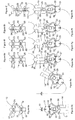
- FIGs 5a to 5h a method for holding located cups using a robotic arm will be described.
- a robotic arm 22 having grippers 23, 24, 25 and 26 is advanced between the milking cups 11, 12, 13 and 14 to the position shown in Figures 5c and 5d .
- Grippers 23, 24, 25 and 26 then grip cups 11, 12, 13 and 14 as shown in Figures 5e and 5f .
- Each gripper 23, 24, 25 and 26 can be moved towards or away from robotic arm 22 via shafts connected to actuators in robotic arm 22 (for example shaft 27 connected to gripper 25 or shaft 28 connected to gripper 26).
- FIGS 7a and 7b show the operation of the valve formed by the bowl inlet and feed line in detail.
- feed line 29 connects to inlet 33 in a straight through fashion.
- FIG 7b when feed line 29 is curved beyond a certain extent one wall of feed line 29 closes the opening of inlet 33 and prevents the application of a vacuum to feed line 29.
- cup 13 may be moved upwardly so that a wall of feed line 29 is forced against inlet 33 of bowl 31 to act as a valve closing feed line 29.
- feed line 30 and inlet 32 Figures 6a and 6b show the cups moved towards robotic arm 22 so as to close feed lines 29 and 30 by forcing a wall of the feed line against the respective inlet 32 and 33.
- the head of the robotic arm then rotates through 180° to invert the cups so that they may be attached to teats 34 and 35 of an animal.
- One cup is elevated at a time above the other cups for attachment to the teats of an animal.
- an actuator elevates gripper 26 which raises cup 14 above the other cups. Raising cup 14 also straightens feed line 30 so that a vacuum is applied to cup 14 facilitating its attachment to teat 35 of an animal.
- Cup 14 may be positioned onto teat 35 via manipulation of robotic arm 22 utilising a conventional vision system to guide the robotic arm. By applying vacuum to one cup at a time a full vacuum may be employed to attach each cup to a teat.
- FIG. 8 to 15 alternative guides for guiding the cups of a milking cluster to desired locations are shown. It will be appreciated that when in their desired locations the cups may be gripped with the robotic milking arm previously described and so gripping the cups with a robotic arm and applying the cups to the teats of animals will not be described in relation to these embodiments - although it will be appreciated that the same method and robotic arm may be used.
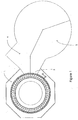
- a milking cluster guide 34 having a central aperture 35 with slots 36 radiating outwardly.
- a main supply line 37 connected to milking cluster 38 passes through central aperture 35.
- the guide is configured and arranged to allow bowl 39 of milking cluster 38 to pass therethrough (due to material flexibility and/or dimensions) and to position cups 40 to 43 of the milking cluster at the distal regions of slots 36 when the milking cluster is drawn through the guide 34.
- the cups may be presented oriented upwardly as shown in figure 9 ready for collection by a robotic arm (as described previously).
- the guide may be positioned in a milking bale below the location of the teats of an animal to be milked to facilitate rapid collection and attachment. In this case a removable cover may be provided to cover the cups during animal movement and uncover the cups before attachment of the cups.
- bowl 44 remains hanging down and extra long feed lines 45 to 48 are employed.
- each feed line 45 to 48 passes through a respective aperture 54 to 57 in guide 53.
- cups 49 to 52 drop off the teats of an animal when the vacuum is shut off then bowl 44 is raised and cups 49 to 52 are positioned adjacent apertures 54 to 57.
- the cups 49 to 52 may then be collected by a robotic arm and attached as previously described.
- Figures 11 and 12 show a variant to the design shown in figures 9 and 10 in which a standard milking cluster is employed having standard lengths for feed lines 58 to 61.
- an actuator (not shown) may be employed to move guide 67 towards or away from bowl 62.
- cups 63 to 66 are located adjacent apertures 68 to 71 in guide 67 ready for collection by a robotic arm. Once collected by a robotic arm guide 67 is moved towards bowl 62 to allow freedom of movement of cups 63 to 66 for attachment.
- Figure 12 shows an inverted arrangement. The arrangement of figure 11 could be inverted to the position shown in figure 12 prior to attachment or guide 67 could be maintained in the orientation shown in figure 12 throughout milking operations.
- Figures 13 to 15 show another embodiment in which a sheath is used to position the cups of a milking cluster.
- a main supply line 73 passes through an aperture 74 in sheath 72.
- the cavity includes longitudinal grooves 81 to 84 configured to receive cups 75 to 78 and position them in known positions for collection by a robotic arm as shown in figures 14 and 15 . Collection and attachment by the robotic arm is thereafter as described above.
- FIG 16 shows an alternative embodiment incorporating a typical milking parlour bale partition 85.
- a frame structure 86 incorporating a sheath 87 to locate the milking cluster bowl, and four scalloped recesses 88 to loosely locate the four cups.
- the retractable line is pulled through a guide in the sheath 87 causing the bowl to locate there at the end of the retraction.
- Guide means within the sheath 87 cause the bowl to be oriented in a repeatable manner.
- the recesses 88 are positioned to thus line up with the approximate hanging locations of the cups, and act as a guide for the robotic gripper (not shown) during cup pick-up.
- FIGs 17a to 17d show how the robotic gripper 22 picks up and holds the cups 13 and 14 in the guide means shown in figure 16 .
- the gripper 22 has been inserted between the left-hand pair of cups 13 and the right-hand pair of cups 14. It is then moved towards the left-hand cups 13 as shown in figure 17b , and the left-hand gripper jaws 25 are closed about the pair of cups 13. Moderate cup misalignment is accommodated by the motion of the gripper jaws 25 crowding the cups 13 into the recesses 88.
- Figure 17c shows the gripper 22 moved to the right, from where the right-hand jaws 26 have closed about the right-hand pair of cups 14.
- the gripper 22 has moved back to the central position from where it can be withdrawn to attach the cups to the cow.
- Figures 18a to 18c show a typical milking cup 13.
- Figure 18a is an external view of the cup.
- Figure 18b shows a cross-section through the cup 13.
- Inside the external shell of the cup 13 is a cup liner 89 which incorporates the cup opening and the vacuum hose 91 to the claw of the bowl (not shown). Between the opening and the hose 91 the liner 89 seals on the cup shell.
- Figure 18c shows an embodiment where the pulsation is paused, and sufficient constant air pressure is applied through the pulsation line fitting 90 to cause the liner 89 to temporarily collapse thus restricting the vacuum flow through the cup.
- This embodiment can be used to close off the vacuum to cups not attached to the cow's teats in order to ensure that cups that are attached to the teats have sufficient vacuum to hold them on.
- the cups may be held using a variety of holding means including suction cups or any other device suitable for holding a milking cup.
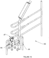
- a milking cluster guide 100 is generally comprised of five main sub-parts: a stand 102, a trolley frame 103, a guide track 104, a guide carriage 105 and a pair of guide arms 106. These sub-parts and their relationship are described in detail below.
- the stand 102 is comprised of frame members that form a base 107 and a framework 108.
- the base 107 is configured so that in use it will rest on a surface and form a stable base for the guide 100, on a surface such as the floor of a milking shed or similar.
- the base 107 and framework 108 are mutually connected and arranged so that the framework 108 extends upwards from the base 107 to form a generally horizontal top mounting portion above the base 107.
- the overall height of the base 107 and framework 108 (and the height of the top mounting portion above the base) can be varied, depending on the relative differences in height between the milking stalls and the surface or floor on which the guide 100 is located, but for most variants will generally be between 75cm and one metre.
- the base 107 is generally formed as a hollow rectangle from galvanised steel tubing or similar.
- Feet 109 are connected to the underside of the base 107 towards each corner on the shorter sides by a threaded connection or similar so that the vertical position of each foot 109 relative to the base 107 can be adjusted over short distances. In this way, the guide 100 can be kept level even if used on uneven or non-horizontal surfaces, by adjusting the position of the feet 109 individually as necessary.
- the framework 108 generally comprises two legs 110 that are connected at or towards the midpoint of each of the shorter sides of the base 107 and which extend vertically upwards.
- a crosspiece 111 is connected to the top of each leg, the crosspieces extending horizontally in parallel with and directly above the shorter sides of the base 107.
- the crosspieces 111 are connected to the legs 110 at generally their midpoint so that the leg 10 bisects the crosspiece 111.
- the upper surfaces of each of the crosspieces 111 provides the top mounting portion.
- Upwardly extending flange plates 113 are connected to the ends of each of the crosspieces 111 to prevent items resting on the crosspieces 111 from slipping off sideways. Ideally, these are also formed from galvanised steel tubing or similar, as the base 107 and framework 108 are required to resist the harsh wet environment of a milking shed.
- the hollow rectangle formed by the members of the base 107 can be used to provide a storage platform, or a platform for the connection of auxiliary items. This can be achieved by adding additional cross-members to form the platform, or connecting items directly to the base 107 or legs 110.
- a junction box 112 can be connected to one of the legs 110 to provide a connection and junction for a power source.
- the trolley frame 103 comprises two rails 103a, 103b connected at their ends by braces 114 so that the rails 103a, 103b are aligned parallel to one another.
- the braces 114 are substantially the same length as the crosspieces 111.
- the rails 103a, 103b are substantially the same length as the long sides of the base 107.
- the braces 114 rest on top of the crosspieces 111 so that the rails 103a, 103b extend from one crosspiece at one end to the crosspiece at the other end.
- the braces 114 are prevented from slipping sideways by the flange plates 113.
- the outer rail 103a is a 'C'-section rail
- the inner rail 103b is an 'L' section.
- the uprights of the rails are aligned towards the outer sides of the guide 100.
- the rails 103a, 103b are formed from anodised aluminium or similar.
- the trolley frame 103 is mounted on the stand 102 so that the guide track 104 can run from one end of the rails 103a, 103b to the other (that is, from one end of the guide 100 to the other lengthways).
- the guide track 104 generally comprises an elongate guide rail assembly 115 and wheel mounting assemblies 116a, 116b.
- the guide carriage 105 is mounted on the guide rail assembly 115 in a manner described in detail below.
- the wheel mounting assemblies 116a, 116b are connected to the underside of the guide rail assembly 115.
- the inner wheel mount 116b is connected at or towards the inner end of the guide rail assembly 115, with the outer wheel mount 116a connected outwards of this ('inwards' and 'outwards' as used in this specification refer to in-use positioning relative to a rotating platform - radially inwards towards or closest to the rotating platform, or radially outwards away or furthest from the rotating platform, unless the context clearly indicates otherwise).
- the outer and inner wheel mounts 116a, 116b are configured so that the inner end of the guide rail assembly 115 is angled upwards, or above, the outer end.
- Each of the wheel mounts 116a, 116b further comprises a wheel 117, the wheel mounts 16a, 16b configured and connected to the guide rail assembly 115 so that the wheels 117 locate into/onto the inner and outer rails 103b, 103a so that the guide track 104 can travel from one end of the rails 103a, 103b to the other. That is, from one end of the guide 100 to the other.
- the wheel mounting assembly and guide rail assembly 115 are connected so that when the wheels 117 are located in/on the rails 103a, 103b, the guide rail assembly 115 is aligned perpendicular to the rails 103a, 103b - that is, so that the mounted guide carriage 105 will travel along the length of the guide rail assembly 115 from one end to the other perpendicular to the rails 103a, 103b.
- the wheels are formed from a metal such as galvanised steel or anodised aluminium.
- a pneumatic cylinder 118 is mounted to the inner wheel mount 116b to provide motive power to move the guide track 104 along the rails 103a, 103b.
- the guide rail assembly 115 comprises an elongate body 115a, formed from galvanised steel 'C'-section or similar with the open face aligned downwards.
- a pair of rods 115b are mounted on top of this, running from end-to-end of the body 115a.
- the guide carriage 105 is mounted to and travels along the length of the rods 115b.
- a pneumatic cylinder 119 is mounted at the inner end of the body 115a and is used for moving the guide carriage 105 along the rods 115b.
- the guide carriage 105 has a main body 105a which is 'U'-shaped.
- the underside of the main body 105a is configured to be slidably mounted to the rods 115b, the pneumatic cylinder 119 providing motive power for the guide carriage 105 on the rods 115b.
- a pair of guide arms 106a, 106b are mounted on the guide carriage 105 as outlined below.
- a pair of guide connectors 120 are mounted at the outer end of each of the upright sides or legs of the 'U'-shaped main body 105a.
- the guide connectors 120 are mounted so that they can rotate around a generally vertically aligned axis.
- a pair of guide arms 106 are mounted to the guide connectors 120 at or close to their inner ends, so that the guide arms 106 extend horizontally outwards from the guide connectors 120.
- the guide arms 106 have the general overall form of straight rods, with an upwards kink or bend formed in each of the arms just inward of their connection to the guide connectors 120.
- the body 105a and guide connectors 120 are configured so that the guide connectors 120 rotate about a generally vertical axis, with the guide arms 106 extending and rotating in a generally horizontal plane.
- the guide connectors 120 are configured so that the guide arms 106 can rotate between an open and a closed position. In the closed position the guide arms 106 extend outwards, parallel to each other and the guide rail assembly 115, above and slightly to each side of the guide rail assembly 115.
- the guide connectors 120 rotate from the closed to the open position so that in the open position, in plan view the arms 106 form a 'V' shape, each guide connector 120 rotating the same amount so that the 'V' has an axis of symmetry in plan view, the axis of symmetry aligned with the axis of the guide rail assembly 115.
- the wider or open end of the 'V' faces inwards so that the 'V' shape tapers or narrows with increasing radius. That is, tapers radially.
- the arms are formed from a metal or plastic, and are at least partly covered on their inwards-facing portions with a resilient spongy material. This material allows for slight misalignment in the relative positions of the cups 124, the arms 106 and the gripper portion 123, acting as a damper for the dangling milking cups before they are crowded and gripped.
- the connectors 120 are moved and operated by a pair of pneumatic cylinders 121 that are mounted on each side of the guide carriage 105.
- the guide arms 106 can operate together, moving at the same or different speeds, or independently, one moving while the other remains stationary.
- the guide 100 is mounted or positioned on the floor of a milking parlour or shed such as the parlour shown in figure 1 .
- a milking parlour having a rotary platform 1 is shown. Animals enter into an entry area 2 and advance to a loading area 3. Once the rotary platform 1 has performed a revolution the cows exit via exit area 4.
- Robotic arm 6 locates the cups for each milking cluster in each bale and attaches the cups to the teats of an animal as it passes the robotic arm 6.
- the guide 100 assists with this process as described below.
- Spreaders 7 keep the animals rear legs spread apart to facilitate operation of the robotic arm through the animal's rear legs.
- Each bale has a milking cluster associated with it which supplies milk to a central milk collection system.
- the milking clusters comprise four teat cups 124 connected to a central collecting bowl or claw via short lengths of tube.
- the collecting bowl is connected to a longer milk tube for collecting and transporting the milk from the teat cups 124, and a longer pulse tube that connects via the bowl to the shorter pulse tubes and the teat to provide a pulsing or milking action.
- the milking cluster is stored with the bowl upwards and the teat cups 124 hanging or dangling below the bowl.
- the guide 100 is co-located with the robot arm 6, mounted on the floor of the parlour close to the periphery of the rotating platform 2, in an area separated by partitions from the loading and entry area 3 and exit area 4.
- the guide 100 is aligned across the periphery of the rotating platform - that is, generally in parallel to a tangent to the rotating platform.
- the robot arm 6 is mounted circumferentially further outwards or behind the guide 100.
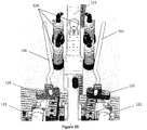
- the guide carriage 105 In the starting position, the guide carriage 105 is positioned at one end of the positioning device - the left of the positioning device as shown in figure 19 . This is towards the direction from which the platform is rotating.
- the guide carriage 105 starts rearward or outward on the rods 115b.
- the guide arms 106 start in the open position (see Figure 20 ).
- a stall partition and associated milking cluster rotate in front of the guide 100 and robot arm 6.
- the robot arm 6 engages to move forward or inwards towards the rotating platform 1.
- the inwards end or part of the robot arm 6 forms a gripper portion 123.
- the gripper portion 123 is similar to that described above with reference to figures 17a to 17d , and comprises a generally cuboid main body, with four pairs of grippers or pincers 125 that extend and retract from two opposed sides of the gripper portion, two pairs on each side arranged along the length at generally the same height on each of the opposed sides, each side mirroring the other.
- the grippers 125 open to fully retract within the body of gripper portion 123 through slots in the side, and pass outwards through the slots, rotating around a central vertically aligned pivot point just behind or inwards of the side wall to close.
- the robot arm 122 has a number of axes around which the members can rotate and move, the sides of the gripper portion 123 are aligned generally vertically when in use.
- the gripper portion 123 passes between the dangling teat cups 124 with the grippers 125 open and retracted into the gripper portion 123, and under the bowl so that two of the teat cups 124 are on each side of the gripper portion 123.
- Pneumatic cylinder 119 activates to move the guide carriage 105 inwards towards the milking cluster.
- the guide carriage is at the end of the rods 115b, or fully forwards and upwards, it is under the gripper portion 123 of the robot arm, with the arms of the 'V' formed by the guide arms 106 extending each side of the four hanging teat cups, roughly halfway along the length of the hanging teat cups.
- the cups 124 are now located between the vertical pincer sides of the gripper portion 123 and the arms 106, as shown in figure 20 .
- the pneumatic cylinders 121 then activate to move the arms 106 to the closed position. As the arms 106 move to the closed position, they move the teat cups 124 inwards and press these against the sides of the gripper portion 123 as shown in figures 21 and 22 .
- the grippers 125 then close, extending/rotating outwards from the sides of the gripper portion 123, rotating closed around each of the teat cups 124 to securely grasp the teat cups 124 against the sides of the gripper portion 123, as shown in figure 22 .
- Pneumatic cylinder 118 now activates to move the guide track 104 along the rails 103a, 103b from left to right (looking inwards towards the centre of the rotating platform 101), following the rotational direction of the platform.
- the robot arm rotates to cause the gripper portion 123 to move with the guide track.
- the pneumatic cylinders 121 now act to disengage the arms 106 and move them from the closed position to the open position.
- the robot arm 6 lifts vertically upwards after the arms 106 are disengaged and lifts the milking cluster upwards, removing this from the partition and rotating it to face upwards so that it can be positioned under an animal to start the milking cycle.
- the guide 100 then resets to the initial position.
- the arrangement described above has several advantages: the combination of the guide track and the guide carriage allow movement of the guide arms both radially and tangentially; the milking clusters used are the same as for existing systems such as manual systems and do not have to be custom-made or tailored to suit a particular shed or environment.
- the arrangement lends itself to a multi-teat system such as the four teat system in general use for cows and existing dairy milking parlours.
- the arrangement described can be used in both rotary platform and herringbone sheds, and there is no minimum or maximum number of stalls or bales. This allows the system to be retrofitted to existing sheds with minimal interference and changes necessary.
- the system described uses a minimal number of movements and operations to collect and move the cups, cutting down on cycle time and increasing the efficiency.
- the teats are collected in a single action and larger differences or discrepancies in position can be compensated for (i.e. the radially tapering openings between the robotic arm and the guide arms allows cups to be acquired in a tapering opening as they both advance towards the cups).
- the robot head can move freely, independently of the positioning device, and the positioning device does not interfere with the operation of the robot arm, especially once the robot arm commences the positioning portion of its cycle - moving the teats to place these on the animal's udder.
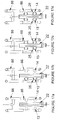
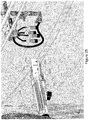
- Robotic arm 126 is provided with a guide bar assembly 127 that can move along rail 128 from the forward position shown in Figure 25 to the retracted position shown in Figure 28 .
- the guide bar assembly 127 includes a guide bar 129 pivotally mounted to a carriage 130 and an actuator 131 which can rotate the guide bar from an open radially diverging configuration for cup acquisition ( Figures 25 and 26 ) to a closed configuration in which the guide bar 129 is generally parallel with the head 132 of robotic arm 126 ( Figure 27 ).
- the guide bar assembly 127 is forward with the guide bar 129 in an open radially diverging configuration for ease of cup acquisition as shown in Figure 25 .
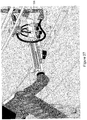
- the robotic arm 126 is then advanced as shown in Figure 26 so that cups 133 and 134 are located within the radially tapering opening defined by head 132 and guide arm 129.
- the tapering opening assists in the easy location of cups 133 and 134 between head 132 and guide arm 129.
- Guide arm 129 is then rotated towards head 132 by actuator 131 until it is generally parallel with head 132 as shown in Figure 27 .
- Grippers 135 to 138 then grip the cups which are now closely contained against head 132 by guide arm 129.
- the guide arm assembly 127 is then retracted along rail 128 to the position shown in Figure 28 with the cups ready to be applied to the teats of an animal by robotic arm 126.
- This embodiment provides a simple integrated design requiring fewer elements and avoiding the need to coordinate relative movements between the robotic arm and guide arms.
- the milking system of the present invention allows automation of a conventional multi-bale milking parlour using conventional milking clusters with a single robotic arm.
- the system allows all four cups of a standard milking cluster to be handled at once achieving high speed cup application.
- the system also allows conventional vacuum switching to be employed.
- the relative simplicity of the milking system makes it a robust and cost effective solution.
Landscapes
- Life Sciences & Earth Sciences (AREA)
- Animal Husbandry (AREA)
- Environmental Sciences (AREA)
- External Artificial Organs (AREA)
Claims (15)
- Système de traite robotisé comprenant:un faisceau de trayeurs comprenant une pluralité de gobelets (133, 134) connectés à une coupole;un rétracteur pour rétracter le faisceau de telle sorte que les gobelets soient suspendus en dessous de la coupole;un bras de robot (126) qui n'est pas attaché de façon permanente au faisceau de trayeurs et qui est agencé de manière à saisir et à tenir la pluralité de gobelets du faisceau lorsqu'ils sont suspendus en dessous de la coupole, et des actionneurs pour déplacer le bras dans le but de faciliter la fixation des gobelets à un animal;caractérisé par un ou plusieurs bras de guidage (129) positionnable(s) par rapport au bras de robot dans une première configuration pour définir une ouverture s'amincissant radialement entre le bras de robot et le bras de guidage afin de faciliter le positionnement des gobelets à l'intérieur de l'ouverture conique, et positionnable(s) par rapport au bras de robot dans une seconde configuration dans laquelle les gobelets sont amenés dans une proximité plus étroite avec les bras de robot à des fins de saisie.
- Système de traite robotisé selon la revendication 1, comprenant une paire de bras de guidage de part et d'autre du bras de robot.
- Système de traite robotisé selon la revendication 1, dans lequel lesdits un ou plusieurs bras de guidage est (sont) monté(s) sur le bras de robot.
- Système de traite robotisé selon la revendication 3, dans lequel le bras de robot comporte des pinces pour saisir les gobelets.
- Système de traite robotisé selon la revendication 4, dans lequel un ou plusieurs bras de guidage est (sont) déplaçable(s) le long du bras de robot à partir d'une position proche des pinces jusqu'à une position éloignée des pinces.
- Système de traite robotisé selon la revendication 1, comprenant un ensemble de guidage comprenant un support et un chariot de guidage monté de façon mobile sur le support, les bras étant montés sur le chariot de guidage.
- Système de traite robotisé selon la revendication 6, dans lequel le support et le chariot de guidage sont mutuellement configurés de manière à permettre au chariot de guidage de se déplacer de façon tangentielle lors de l'utilisation.
- Système de traite robotisé selon la revendication 7, comprenant en outre un rail de guidage monté entre le chariot de guidage et le support, le chariot de guidage et le rail de guidage étant mutuellement configurés de manière à permettre au chariot de guidage de se déplacer radialement vers l'intérieur et vers l'extérieur sur le rail de guidage lors de l'utilisation, le rail de guidage et le support étant mutuellement configurés de manière à permettre au rail de guidage de se déplacer de façon tangentielle sur le support lors de l'utilisation.
- Système de traite robotisé selon la revendication 6, dans lequel les gobelets sont maintenus par des pinces sur le bras de robot, dans lequel les pinces se présentent sous la forme d'une paire de bras opposés dont les mâchoires internes sont configurées de manière à saisir un gobelet, et dans lequel deux paires de pinces sont prévues dos à dos orientées dans des directions opposées sur une partie de pince du bras de robot, la partie de pince et le guide étant mutuellement configurés de telle sorte que la partie de pince puisse juste se positionner entre les bras fermés lorsque les pinces de chaque côté sont fermées.
- Système de traite robotisé selon la revendication 9, dans lequel le bras de robot est agencé de manière à opérer entre les pattes arrière d'un animal lors de la fixation des gobelets, et dans lequel chaque faisceau de trayeurs se rétracte dans une position généralement connue lors de son détachement d'un animal.
- Bras de traite robotisé, comprenant;
un bras de robot (126) agencé de manière à saisir et à tenir une pluralité de gobelets (133, 134) d'un faisceau de trayeurs comprenant des actionneurs pour déplacer le bras afin de faciliter la fixation des gobelets à un animal;
caractérisé par un ou plusieurs bras de guidage (129) positionnable(s) par rapport au bras de robot dans une première configuration pour définir une ouverture s'amincissant radialement entre le bras de robot et le bras de guidage afin de faciliter le positionnement des gobelets à l'intérieur de l'ouverture conique, et positionnable(s) par rapport au bras de robot dans une seconde configuration dans laquelle les gobelets sont amenés dans une proximité plus étroite avec le bras de robot à des fins de saisie. - Bras de traite robotisé selon la revendication 11, comprenant une paire de bras de guidage de part et d'autre du bras de robot.
- Bras de traite robotisé selon la revendication 11, dans lequel le bras de robot comprend des pinces pour saisir les gobelets.
- Bras de traite robotisé selon la revendication 13, dans lequel un ou plusieurs bras de guidage est (sont) déplaçable(s) le long du bras de robot à partir d'une position proche des pinces jusqu'à une position éloignée des pinces.
- Procédé pour positionner un guide de faisceau de trayeurs, comprenant les étapes suivantes:positionner une pluralité de pinces (125) configurées de manière à saisir le corps d'un gobelet trayeur (124) à travers le centre d'un faisceau de gobelets trayeurs (124) suspendu en dessous d'une coupole associée;positionner une paire de bras de guidage (106) dans une première configuration dans laquelle ils divergent l'un de l'autre et faire tourner de façon relative les bras de guidage vers l'intérieur jusqu'à une seconde configuration de telle sorte que les bras de guidage soient positionnés autour de l'extérieur du faisceau; etdéplacer les bras de guidage en direction du centre du faisceau afin de pousser les gobelets trayeurs dans une position d'engagement avec les pinces.
Priority Applications (1)
| Application Number | Priority Date | Filing Date | Title |
|---|---|---|---|
| PL15749305T PL3104686T3 (pl) | 2008-03-11 | 2015-02-12 | Ramię robota udojowego i sposób podłączania kubków udojowych |
Applications Claiming Priority (3)
| Application Number | Priority Date | Filing Date | Title |
|---|---|---|---|
| NZ566631A NZ566631A (en) | 2008-03-11 | 2008-03-11 | A robotic milking system and a method of attaching milking cups |
| US14/181,127 US9402364B2 (en) | 2008-03-11 | 2014-02-14 | Robot milking arm and a method of attaching milking cups |
| PCT/NZ2015/050013 WO2015122784A2 (fr) | 2008-03-11 | 2015-02-12 | Bras de robot de traite et procédé permettant d'attacher des gobelets trayeurs |
Publications (2)
| Publication Number | Publication Date |
|---|---|
| EP3104686A2 EP3104686A2 (fr) | 2016-12-21 |
| EP3104686B1 true EP3104686B1 (fr) | 2018-07-04 |
Family
ID=53800732
Family Applications (1)
| Application Number | Title | Priority Date | Filing Date |
|---|---|---|---|
| EP15749305.7A Not-in-force EP3104686B1 (fr) | 2008-03-11 | 2015-02-12 | Bras de robot de traite et procédé permettant d'attacher des gobelets trayeurs |
Country Status (4)
| Country | Link |
|---|---|
| EP (1) | EP3104686B1 (fr) |
| AU (1) | AU2015217619B2 (fr) |
| PL (1) | PL3104686T3 (fr) |
| WO (1) | WO2015122784A2 (fr) |
Family Cites Families (5)
| Publication number | Priority date | Publication date | Assignee | Title |
|---|---|---|---|---|
| SE430559B (sv) | 1982-04-08 | 1983-11-28 | Alfa Laval Ab | Sett att mjolka och anordning herfor |
| NL9401070A (nl) | 1994-06-28 | 1996-02-01 | Maasland Nv | Inrichting voor het automatisch melken van dieren. |
| SE9701310D0 (sv) * | 1997-04-11 | 1997-04-11 | Alfa Laval Agri Ab | A teatcup magazine, a milking arrangement, and a method of handling a teatcup |
| WO2009113884A2 (fr) * | 2008-03-11 | 2009-09-17 | Scott Milktech Limited | Bras robotisé de traite et procédé permettant d’attacher des manchons de traite |
| WO2010060693A1 (fr) * | 2008-11-26 | 2010-06-03 | Delaval Holding Ab | Manipulation de gobelets trayeurs |
-
2015
- 2015-02-12 AU AU2015217619A patent/AU2015217619B2/en not_active Ceased
- 2015-02-12 WO PCT/NZ2015/050013 patent/WO2015122784A2/fr active Application Filing
- 2015-02-12 PL PL15749305T patent/PL3104686T3/pl unknown
- 2015-02-12 EP EP15749305.7A patent/EP3104686B1/fr not_active Not-in-force
Non-Patent Citations (1)
| Title |
|---|
| None * |
Also Published As
| Publication number | Publication date |
|---|---|
| WO2015122784A2 (fr) | 2015-08-20 |
| AU2015217619A1 (en) | 2016-08-25 |
| WO2015122784A3 (fr) | 2016-04-28 |
| EP3104686A2 (fr) | 2016-12-21 |
| PL3104686T3 (pl) | 2019-01-31 |
| AU2015217619B2 (en) | 2018-08-23 |
Similar Documents
| Publication | Publication Date | Title |
|---|---|---|
| DK3104686T3 (en) | ROBOT MILK ARM AND PROCEDURE FOR DETERMINING MILK COPPER | |
| US8670867B2 (en) | Robot milking arm and a method of attaching milking cups | |
| US9549530B2 (en) | Milking apparatus and a method for presenting a teat cup for attaching to an animal | |
| US9480237B2 (en) | Milking parlour for animals | |
| EP3516955B1 (fr) | Salle de traite rotative pour traite automatique | |
| US9675043B2 (en) | Rotary parlour arranged to house animals to be milked | |
| US20150189854A1 (en) | Space Divider of a Milking Parlor Arrangement, and Milking Parlor Arrangement | |
| WO2003098998A1 (fr) | Dispositif pour nettoyer les mamelles d'un animal et stalle de traite equipee de ce dispositif | |
| EP3096604B1 (fr) | Pince pour disposer des gobelets trayeurs sur un animal de traite, bras de robot et machine de traite la comprenant, et son procédé | |
| EP3104686B1 (fr) | Bras de robot de traite et procédé permettant d'attacher des gobelets trayeurs | |
| EP3389365B1 (fr) | Dispositif de traite | |
| EP2790493B1 (fr) | Salle de traite rotative agencée pour accueillir des animaux à traire | |
| NZ722922B2 (en) | A robot milking arm and a method of attaching milking cups | |
| RU2794184C2 (ru) | Опорный рычаг доильного аппарата с автоматическим сбросом для шланговой опоры | |
| JPH09121706A (ja) | 搾乳機械 |
Legal Events
| Date | Code | Title | Description |
|---|---|---|---|
| PUAI | Public reference made under article 153(3) epc to a published international application that has entered the european phase |
Free format text: ORIGINAL CODE: 0009012 |
|
| STAA | Information on the status of an ep patent application or granted ep patent |
Free format text: STATUS: REQUEST FOR EXAMINATION WAS MADE |
|
| 17P | Request for examination filed |
Effective date: 20160811 |
|
| AK | Designated contracting states |
Kind code of ref document: A2 Designated state(s): AL AT BE BG CH CY CZ DE DK EE ES FI FR GB GR HR HU IE IS IT LI LT LU LV MC MK MT NL NO PL PT RO RS SE SI SK SM TR |
|
| AX | Request for extension of the european patent |
Extension state: BA ME |
|
| DAX | Request for extension of the european patent (deleted) | ||
| RAP1 | Party data changed (applicant data changed or rights of an application transferred) |
Owner name: SCOTT TECHNOLOGY NZ LIMITED |
|
| GRAP | Despatch of communication of intention to grant a patent |
Free format text: ORIGINAL CODE: EPIDOSNIGR1 |
|
| STAA | Information on the status of an ep patent application or granted ep patent |
Free format text: STATUS: GRANT OF PATENT IS INTENDED |
|
| INTG | Intention to grant announced |
Effective date: 20180125 |
|
| GRAS | Grant fee paid |
Free format text: ORIGINAL CODE: EPIDOSNIGR3 |
|
| GRAA | (expected) grant |
Free format text: ORIGINAL CODE: 0009210 |
|
| STAA | Information on the status of an ep patent application or granted ep patent |
Free format text: STATUS: THE PATENT HAS BEEN GRANTED |
|
| AK | Designated contracting states |
Kind code of ref document: B1 Designated state(s): AL AT BE BG CH CY CZ DE DK EE ES FI FR GB GR HR HU IE IS IT LI LT LU LV MC MK MT NL NO PL PT RO RS SE SI SK SM TR |
|
| REG | Reference to a national code |
Ref country code: GB Ref legal event code: FG4D |
|
| REG | Reference to a national code |
Ref country code: CH Ref legal event code: EP |
|
| REG | Reference to a national code |
Ref country code: AT Ref legal event code: REF Ref document number: 1013508 Country of ref document: AT Kind code of ref document: T Effective date: 20180715 |
|
| REG | Reference to a national code |
Ref country code: IE Ref legal event code: FG4D |
|
| REG | Reference to a national code |
Ref country code: DE Ref legal event code: R096 Ref document number: 602015013111 Country of ref document: DE |
|
| REG | Reference to a national code |
Ref country code: NL Ref legal event code: FP |
|
| REG | Reference to a national code |
Ref country code: DK Ref legal event code: T3 Effective date: 20181016 |
|
| REG | Reference to a national code |
Ref country code: ES Ref legal event code: FG2A Ref document number: 2689434 Country of ref document: ES Kind code of ref document: T3 Effective date: 20181114 |
|
| REG | Reference to a national code |
Ref country code: LT Ref legal event code: MG4D |
|
| REG | Reference to a national code |
Ref country code: AT Ref legal event code: MK05 Ref document number: 1013508 Country of ref document: AT Kind code of ref document: T Effective date: 20180704 |
|
| PG25 | Lapsed in a contracting state [announced via postgrant information from national office to epo] |
Ref country code: IS Free format text: LAPSE BECAUSE OF FAILURE TO SUBMIT A TRANSLATION OF THE DESCRIPTION OR TO PAY THE FEE WITHIN THE PRESCRIBED TIME-LIMIT Effective date: 20181104 Ref country code: AT Free format text: LAPSE BECAUSE OF FAILURE TO SUBMIT A TRANSLATION OF THE DESCRIPTION OR TO PAY THE FEE WITHIN THE PRESCRIBED TIME-LIMIT Effective date: 20180704 Ref country code: SE Free format text: LAPSE BECAUSE OF FAILURE TO SUBMIT A TRANSLATION OF THE DESCRIPTION OR TO PAY THE FEE WITHIN THE PRESCRIBED TIME-LIMIT Effective date: 20180704 Ref country code: NO Free format text: LAPSE BECAUSE OF FAILURE TO SUBMIT A TRANSLATION OF THE DESCRIPTION OR TO PAY THE FEE WITHIN THE PRESCRIBED TIME-LIMIT Effective date: 20181004 Ref country code: GR Free format text: LAPSE BECAUSE OF FAILURE TO SUBMIT A TRANSLATION OF THE DESCRIPTION OR TO PAY THE FEE WITHIN THE PRESCRIBED TIME-LIMIT Effective date: 20181005 Ref country code: FI Free format text: LAPSE BECAUSE OF FAILURE TO SUBMIT A TRANSLATION OF THE DESCRIPTION OR TO PAY THE FEE WITHIN THE PRESCRIBED TIME-LIMIT Effective date: 20180704 Ref country code: RS Free format text: LAPSE BECAUSE OF FAILURE TO SUBMIT A TRANSLATION OF THE DESCRIPTION OR TO PAY THE FEE WITHIN THE PRESCRIBED TIME-LIMIT Effective date: 20180704 Ref country code: BG Free format text: LAPSE BECAUSE OF FAILURE TO SUBMIT A TRANSLATION OF THE DESCRIPTION OR TO PAY THE FEE WITHIN THE PRESCRIBED TIME-LIMIT Effective date: 20181004 Ref country code: LT Free format text: LAPSE BECAUSE OF FAILURE TO SUBMIT A TRANSLATION OF THE DESCRIPTION OR TO PAY THE FEE WITHIN THE PRESCRIBED TIME-LIMIT Effective date: 20180704 Ref country code: CZ Free format text: LAPSE BECAUSE OF FAILURE TO SUBMIT A TRANSLATION OF THE DESCRIPTION OR TO PAY THE FEE WITHIN THE PRESCRIBED TIME-LIMIT Effective date: 20180704 |
|
| PG25 | Lapsed in a contracting state [announced via postgrant information from national office to epo] |
Ref country code: HR Free format text: LAPSE BECAUSE OF FAILURE TO SUBMIT A TRANSLATION OF THE DESCRIPTION OR TO PAY THE FEE WITHIN THE PRESCRIBED TIME-LIMIT Effective date: 20180704 Ref country code: LV Free format text: LAPSE BECAUSE OF FAILURE TO SUBMIT A TRANSLATION OF THE DESCRIPTION OR TO PAY THE FEE WITHIN THE PRESCRIBED TIME-LIMIT Effective date: 20180704 Ref country code: AL Free format text: LAPSE BECAUSE OF FAILURE TO SUBMIT A TRANSLATION OF THE DESCRIPTION OR TO PAY THE FEE WITHIN THE PRESCRIBED TIME-LIMIT Effective date: 20180704 |
|
| PGFP | Annual fee paid to national office [announced via postgrant information from national office to epo] |
Ref country code: NL Payment date: 20190218 Year of fee payment: 5 |
|
| REG | Reference to a national code |
Ref country code: DE Ref legal event code: R097 Ref document number: 602015013111 Country of ref document: DE |
|
| PG25 | Lapsed in a contracting state [announced via postgrant information from national office to epo] |
Ref country code: RO Free format text: LAPSE BECAUSE OF FAILURE TO SUBMIT A TRANSLATION OF THE DESCRIPTION OR TO PAY THE FEE WITHIN THE PRESCRIBED TIME-LIMIT Effective date: 20180704 Ref country code: EE Free format text: LAPSE BECAUSE OF FAILURE TO SUBMIT A TRANSLATION OF THE DESCRIPTION OR TO PAY THE FEE WITHIN THE PRESCRIBED TIME-LIMIT Effective date: 20180704 |
|
| PGFP | Annual fee paid to national office [announced via postgrant information from national office to epo] |
Ref country code: FI Payment date: 20190225 Year of fee payment: 9 Ref country code: ES Payment date: 20190321 Year of fee payment: 5 |
|
| PLBE | No opposition filed within time limit |
Free format text: ORIGINAL CODE: 0009261 |
|
| STAA | Information on the status of an ep patent application or granted ep patent |
Free format text: STATUS: NO OPPOSITION FILED WITHIN TIME LIMIT |
|
| PG25 | Lapsed in a contracting state [announced via postgrant information from national office to epo] |
Ref country code: SK Free format text: LAPSE BECAUSE OF FAILURE TO SUBMIT A TRANSLATION OF THE DESCRIPTION OR TO PAY THE FEE WITHIN THE PRESCRIBED TIME-LIMIT Effective date: 20180704 Ref country code: SM Free format text: LAPSE BECAUSE OF FAILURE TO SUBMIT A TRANSLATION OF THE DESCRIPTION OR TO PAY THE FEE WITHIN THE PRESCRIBED TIME-LIMIT Effective date: 20180704 |
|
| PGFP | Annual fee paid to national office [announced via postgrant information from national office to epo] |
Ref country code: DK Payment date: 20190220 Year of fee payment: 5 |
|
| 26N | No opposition filed |
Effective date: 20190405 |
|
| PG25 | Lapsed in a contracting state [announced via postgrant information from national office to epo] |
Ref country code: SI Free format text: LAPSE BECAUSE OF FAILURE TO SUBMIT A TRANSLATION OF THE DESCRIPTION OR TO PAY THE FEE WITHIN THE PRESCRIBED TIME-LIMIT Effective date: 20180704 |
|
| REG | Reference to a national code |
Ref country code: CH Ref legal event code: PL |
|
| PG25 | Lapsed in a contracting state [announced via postgrant information from national office to epo] |
Ref country code: LU Free format text: LAPSE BECAUSE OF NON-PAYMENT OF DUE FEES Effective date: 20190212 Ref country code: MC Free format text: LAPSE BECAUSE OF FAILURE TO SUBMIT A TRANSLATION OF THE DESCRIPTION OR TO PAY THE FEE WITHIN THE PRESCRIBED TIME-LIMIT Effective date: 20180704 |
|
| REG | Reference to a national code |
Ref country code: BE Ref legal event code: MM Effective date: 20190228 |
|
| PG25 | Lapsed in a contracting state [announced via postgrant information from national office to epo] |
Ref country code: CH Free format text: LAPSE BECAUSE OF NON-PAYMENT OF DUE FEES Effective date: 20190228 Ref country code: LI Free format text: LAPSE BECAUSE OF NON-PAYMENT OF DUE FEES Effective date: 20190228 |
|
| PG25 | Lapsed in a contracting state [announced via postgrant information from national office to epo] |
Ref country code: BE Free format text: LAPSE BECAUSE OF NON-PAYMENT OF DUE FEES Effective date: 20190228 |
|
| PG25 | Lapsed in a contracting state [announced via postgrant information from national office to epo] |
Ref country code: TR Free format text: LAPSE BECAUSE OF FAILURE TO SUBMIT A TRANSLATION OF THE DESCRIPTION OR TO PAY THE FEE WITHIN THE PRESCRIBED TIME-LIMIT Effective date: 20180704 |
|
| PG25 | Lapsed in a contracting state [announced via postgrant information from national office to epo] |
Ref country code: PT Free format text: LAPSE BECAUSE OF FAILURE TO SUBMIT A TRANSLATION OF THE DESCRIPTION OR TO PAY THE FEE WITHIN THE PRESCRIBED TIME-LIMIT Effective date: 20181104 Ref country code: MT Free format text: LAPSE BECAUSE OF NON-PAYMENT OF DUE FEES Effective date: 20190212 |
|
| REG | Reference to a national code |
Ref country code: DK Ref legal event code: EBP Effective date: 20200229 |
|
| REG | Reference to a national code |
Ref country code: NL Ref legal event code: MM Effective date: 20200301 |
|
| PG25 | Lapsed in a contracting state [announced via postgrant information from national office to epo] |
Ref country code: NL Free format text: LAPSE BECAUSE OF NON-PAYMENT OF DUE FEES Effective date: 20200301 |
|
| PG25 | Lapsed in a contracting state [announced via postgrant information from national office to epo] |
Ref country code: DK Free format text: LAPSE BECAUSE OF NON-PAYMENT OF DUE FEES Effective date: 20200229 |
|
| PGFP | Annual fee paid to national office [announced via postgrant information from national office to epo] |
Ref country code: FR Payment date: 20210226 Year of fee payment: 7 Ref country code: IE Payment date: 20210217 Year of fee payment: 7 |
|
| PG25 | Lapsed in a contracting state [announced via postgrant information from national office to epo] |
Ref country code: CY Free format text: LAPSE BECAUSE OF FAILURE TO SUBMIT A TRANSLATION OF THE DESCRIPTION OR TO PAY THE FEE WITHIN THE PRESCRIBED TIME-LIMIT Effective date: 20180704 |
|
| PGFP | Annual fee paid to national office [announced via postgrant information from national office to epo] |
Ref country code: DE Payment date: 20210217 Year of fee payment: 7 Ref country code: GB Payment date: 20210224 Year of fee payment: 7 |
|
| PG25 | Lapsed in a contracting state [announced via postgrant information from national office to epo] |
Ref country code: HU Free format text: LAPSE BECAUSE OF FAILURE TO SUBMIT A TRANSLATION OF THE DESCRIPTION OR TO PAY THE FEE WITHIN THE PRESCRIBED TIME-LIMIT; INVALID AB INITIO Effective date: 20150212 |
|
| PG25 | Lapsed in a contracting state [announced via postgrant information from national office to epo] |
Ref country code: ES Free format text: LAPSE BECAUSE OF NON-PAYMENT OF DUE FEES Effective date: 20200213 |
|
| PG25 | Lapsed in a contracting state [announced via postgrant information from national office to epo] |
Ref country code: IT Free format text: LAPSE BECAUSE OF NON-PAYMENT OF DUE FEES Effective date: 20200212 |
|
| PG25 | Lapsed in a contracting state [announced via postgrant information from national office to epo] |
Ref country code: MK Free format text: LAPSE BECAUSE OF FAILURE TO SUBMIT A TRANSLATION OF THE DESCRIPTION OR TO PAY THE FEE WITHIN THE PRESCRIBED TIME-LIMIT Effective date: 20180704 |
|
| PG25 | Lapsed in a contracting state [announced via postgrant information from national office to epo] |
Ref country code: PL Free format text: LAPSE BECAUSE OF NON-PAYMENT OF DUE FEES Effective date: 20200212 |
|
| REG | Reference to a national code |
Ref country code: DE Ref legal event code: R119 Ref document number: 602015013111 Country of ref document: DE |
|
| GBPC | Gb: european patent ceased through non-payment of renewal fee |
Effective date: 20220212 |
|
| PG25 | Lapsed in a contracting state [announced via postgrant information from national office to epo] |
Ref country code: FR Free format text: LAPSE BECAUSE OF NON-PAYMENT OF DUE FEES Effective date: 20220228 |
|
| PG25 | Lapsed in a contracting state [announced via postgrant information from national office to epo] |
Ref country code: IE Free format text: LAPSE BECAUSE OF NON-PAYMENT OF DUE FEES Effective date: 20220212 Ref country code: GB Free format text: LAPSE BECAUSE OF NON-PAYMENT OF DUE FEES Effective date: 20220212 Ref country code: DE Free format text: LAPSE BECAUSE OF NON-PAYMENT OF DUE FEES Effective date: 20220901 |