EP3104478A1 - Elektrische vorrichtung mit etikettenträger - Google Patents
Elektrische vorrichtung mit etikettenträger Download PDFInfo
- Publication number
- EP3104478A1 EP3104478A1 EP16173435.5A EP16173435A EP3104478A1 EP 3104478 A1 EP3104478 A1 EP 3104478A1 EP 16173435 A EP16173435 A EP 16173435A EP 3104478 A1 EP3104478 A1 EP 3104478A1
- Authority
- EP
- European Patent Office
- Prior art keywords
- mounting frame
- electric device
- support member
- label carrier
- cut
- Prior art date
- Legal status (The legal status is an assumption and is not a legal conclusion. Google has not performed a legal analysis and makes no representation as to the accuracy of the status listed.)
- Granted
Links
Images


Classifications
-
- H—ELECTRICITY
- H02—GENERATION; CONVERSION OR DISTRIBUTION OF ELECTRIC POWER
- H02G—INSTALLATION OF ELECTRIC CABLES OR LINES, OR OF COMBINED OPTICAL AND ELECTRIC CABLES OR LINES
- H02G3/00—Installations of electric cables or lines or protective tubing therefor in or on buildings, equivalent structures or vehicles
- H02G3/02—Details
- H02G3/08—Distribution boxes; Connection or junction boxes
- H02G3/14—Fastening of cover or lid to box
Definitions
- the present invention relates to an electric device to be installed into or onto a wall. More particular, the invention relates to an electric device with a label carrier and to a label carrier for use with such an electric device.
- Electric devices with label carriers mostly comprise a mounting frame, a cover frame and a label carrier.
- the mounting frame is designed to be fixed onto a wall and to comprise an electric function, e.g. a switch or a power socket.
- the electric function may then be mounted in a cavity in the wall, or, if the electric function is small, may be mounted onto the front of the mounting frame.
- the cover frame is designed to be fixed onto the mounting frame and is provided with a window opening.
- the label carrier is designed to be placed between the mounting frame and the cover frame in front of the window opening.
- EP 2 383 852 An example of an electric installation device with label carrier is described in EP 2 383 852 . More specifically, EP 2 383 852 describes an electric installation device comprising a mounting frame onto which a label carrier is attached using spring clips.
- DE 10 2013 100 909 describes another similar example of an electric installation device.
- the device described in DE 10 2013 100 909 similarly contains a mounting frame and a label carrier.
- the mounting frame is provided with retaining elements onto which sliding elements are attached.
- the label carrier can be attached to these sliding elements.
- the sliding elements are adjustable in height relative to the retaining elements.
- a disadvantage of the electric devices described above is that multiple small fastening parts are needed to attach the label carrier onto the installation frame, making the installation complex.
- a further objective is to provide a way for an electric function, e.g. a power socket, a switch, a data connection, etc. to be labelled such that the label remains attached to the installation frame, and thus to the electric function, even when the cover frame is not attached to the electric device. Therefore, the present invention provides an electric device for being installed into or onto a wall.
- the electric device comprises at least one electric function and at least one mounting frame for fixing the electric device onto a wall and adapted to carry the at least one electric function.
- the electric device furthermore comprises a cover frame adapted to be fixed onto the at least one mounting frame, the cover frame being provided with at least one window opening and at least one label carrier to be placed between the at least one mounting frame and the cover frame in front of the at least one window opening.
- each of the at least one label carrier has an elongated middle part with a first and second end, the first end having a first support member and the second end having a second support member.
- each of the at least one mounting frame is provided with a first cut-out for providing the first support member to the back of the mounting frame and with a second cut-out for providing the second support member to the back of the mounting frame, the first and second cut-outs being such that, when installed, the first and second support members of the label carrier are placed against the back of the mounting frame whilst the elongated middle part of the label carrier is located at the front of the mounting frame.
- An electric device is distinguished from electric devices know in the art in that the elongated middle part of the label carrier is, when mounted, located at the front of the mounting frame and the first and second end of the label carrier are located at the back of the mounting frame.
- An electric device has as an advantage that no additional means are required to fix the label carrier to the mounting frame. More in particular, the label carrier and the mounting frame are adapted in such a way that the label carrier can be installed in a fixed position onto the mounting frame, and stays on the mounting frame even when the cover frame is removed.
- the first and second cut-outs may preferably be adjacent to the outer perimeter of the mounting frame, preferably adjacent to an upper edge or a lower edge of the mounting frame. In this way, it will be very simple to fix the label carrier to the mounting frame, and the label carrier can be installed near an edge of the mounting frame.
- the mounting frame may preferably be provided with a first protrusion and a second protrusion adjacent to respectively the first cut-out and the second cut-out. These first and second protrusions may preferably extend with respect to a plane of the mounting frame at the front side thereof.
- the first and second support member may preferably be adapted to extend behind the first and second protrusion. Even more preferably, the first and second protrusion may extend so far from the plane of the mounting frame that the first and second support member do not extend from the back side of the mounting frame. In that way, protruding parts from the back side of the mounting frame may be avoided, and the mounting frame can, when installed, at all times make contact to a flat wall along its entire periphery.
- the mounting frame may have a first length
- the label carrier may have a second length which is substantially equal to the first length.
- the first and second support member can mainly be positioned in a first and a second corner of the mounting frame and the label carrier may extend over almost the entire length, for example, over almost the entire upper or lower edge of the installation frame. Consequently, the first and second protrusions may preferably be positioned in two corners of the mounting frame, for example in the two upper corners of the mounting frame.
- the label carrier may have a stepped transition between the first and the second support member and the middle part, such that the first and the second support member extend mainly in a first plane and the middle part extends mainly in a second plane, the second plane being substantially parallel to the first plane.
- the first and second support member can extend at the back side of the mounting frame, whilst the middle part extends at the front side of the mounting frame, and whereby the transition of the first support member to the middle part is positioned in the first cut-out and the transition of the second support member to the middle part is positioned in the second cut-out.
- the mounting frame may, according to embodiments of the invention, at its back side be provided with a first and a second thickening, and the first and second support members may respectively be provided with a first and a second.
- the first and second thickening are complementary to the first and second opening, such that, when mounted, the first thickening is positioned in the first opening, and the second thickening is positioned in the second opening.
- the mounting frame may be provided with a first and second opening and the first and second support member may, at the front side, be provided a first and second complementary thickening, such that, when mounted, the first and second thickening of the support members fit into respectively the first and second opening in the mounting frame.
- the thickenings can be implemented as joggles.
- the label carrier may preferably be a long and narrow carrier, and the first and second cut-outs may preferably be positioned near an upper or lower edge of the mounting frame.
- the first and second cut-out may be symmetrically positioned between respectively the center of the mounting frame's upper edge and a first upper corner, and between the center of the mounting frame's upper edge and a second upper corner.
- the first and second cut-out may similarly be positioned symmetrically on the mounting frame's lower edge.
- the electric device may further comprise a window that can be fixed in the window opening of the cover frame.
- a window can be fixed onto the middle part of the label carrier.
- the window may preferably be made of a transparent plastic, for example a transparent polycarbonate.
- the window can be welded or glued in the window opening of the cover frame or can be clamped onto the middle part of the label carrier.
- the electric function may be one of a power socket, a switch, a dimmer, a data connection or an RF transmitter.
- the shape of the cover frame can be adapted depending on the electric function to be installed. Additionally a central plate or a button can be provided that can be mounted onto the front of the mounting frame, the cover frame thereby extending around the central plate or button.
- the label carrier When fixing the electric function to the flush-mounted box, for example using clamps or screws, the label carrier will be further locked to prevent it from being removed after installation, unless the entire electric device is removed.
- the present invention can equally be used for applications with one electric function as well as for applications where multiple electric functions have to be fixed onto or into a wall, whereby one common cover frame is provided for multiple mounting frames.
- a label carrier will be provided for each mounting frame, and therefore for each of the electric functions, whilst one common cover frame is provided with multiple window openings.
- the label carrier can be provided with a self-adhesive label.
- the label carrier can be directly written upon, for example using laser engraving.
- the invention further provides a label carrier for use in an electric device according to embodiments of the invention and with properties as described above.
- the present invention provides an electric device for being installed into or onto a wall.
- the electric device comprises at least one electric function, at least one mounting frame for fixing the electric device onto a wall and being adapted to carry the at least one electric function and a cover frame adapted to be fixed onto the at least one mounting frame, the cover frame being provided with at least one window opening.
- the electric device furthermore comprises at least one label carrier to be placed between the at least one mounting frame and the cover frame in front of the at least one window opening.
- each of the at least one label carrier has an elongated middle part with a first and second end, the first end having a first support member and the second end having a second support member.
- each of the at least one mounting frame is provided with a first cut-out providing the first support member to the back of the mounting frame and with a second cut-out for providing the second support member to the back of the mounting frame. The first and second cut-out are such that, when installed, the first and second support member are placed against the back of the mounting frame whilst the middle part is located at the front of the mounting frame.
- An electric device has as an advantage that no additional means are required to fix the label carrier to the mounting frame. More in particular, the label carrier and the mounting frame are adapted in such a way that the label carrier can be installed in a fixed position onto the mounting frame, and stays on the mounting frame even when the cover frame is removed.
- FIGS 1A and 1B illustrate a first embodiment of an electric device 1 according to the invention.
- the electric device 1 comprises at least one electric function 50 (not shown in Figures 1A and 1B but provided at the rear or front of the mounting frame 10, typically behind a central plate 60 or a button 60) into a wall.
- the electric function 50 may be any electric function known by a person skilled in the art that is suitable for being built in a box in the wall, such as for example but not limited to a power socket, a switch, a dimmer, a data connection or an RF transmitter.
- the electric device 1 comprises at least one mounting frame 10 for fixing the electric device 1 onto the wall.
- the mounting frame 10 is adapted to carry the electric function 50 and is provided with a number of holes 19 for screws, such that the installation frame 10 can be fixed onto the wall, whereby an electric function 50, provided at the rear of the mounting frame 10, is then located inside a cavity or box in the wall.
- the electric device 1 furthermore comprises a cover frame 20 adapted to be fixed onto the at least one mounting frame 10.
- the cover frame 20 is provided with at least one window opening 21 for exposing the electric function 10.
- the electric device comprises at least one label carrier 30.
- the number of label carriers 30 may be equal to the number of mounting frames 10, but does not necessarily has to be so.
- the electric device 1 may comprise more mounting frames 10, and thus more electric functions 60, than it comprises label carriers 30.
- a common cover frame 20 may be provided.
- the electric device 1 will be described as having one mounting frame 10 carrying one function 10 and comprising one label carrier 30. However, it has to be understood that this is only for the ease of explaining the invention and is not intended to limit the invention in any way.
- the electric device 1 may comprise as many mounting frames 10, and thus functions 50, and label carriers 30 as is appropriate for a particular application.
- the electric device 1 may comprise two, three or more mounting frames 10 and thus functions 50, as required for the application.
- the label carrier 30 is adapted to be placed between the at least one mounting frame 10 and the cover frame 20.
- the label carrier 30 comprises an elongate middle part 33 and is provided at a first end with a first support member 31 and at a second end with a second support member 32.
- the middle part 33 and the first and second support member 31, 32 may preferably be moulded as a single element.
- the mounting frame 10 is provided with a first cut-out 11 for fitting the first support member 31 to the back of the mounting frame 10 and with a second cut-out 12 for fitting the second support member 32 to the back of the mounting frame 10.
- the label carrier 30 is fixed to the mounting frame 10, whereby the first and second support members 31, 32 are located at the back of the mounting frame 10 and the elongated middle part 33 is located at the front of the mounting frame 10, as is illustrated in Figure 1A .
- the first and second cut-out 11, 12 are preferably located adjacent to the outer periphery of the mounting frame 10, and then again preferably to an upper edge or a lower edge of the mounting frame 10.
- the mounting frame 10 may be provided with a first protrusion 13 and a second protrusion 14 next to respectively the first cut-out 11 and the second cut-out 12.
- the first and second protrusion 13, 14 extend with respect to a plane of the mounting frame 10, at the front side thereof and the first and second support member 31, 32 are adapted to extend behind the first and second protrusion 13, 14.
- the first and second protrusion 13, 14 extend exactly so far with respect to the plane of the mounting frame that, when the mounting frame 10 is fixed onto a wall, the first support member 31 and the second support member 32 do not protrude to the rear of the mounting frame 10, such that the rear of the mounting frame 10 can be mounted flush onto the wall.
- the first support member 31 is preferably fitted to the back of the first protrusion 13 and the second support member 32 is preferably fitted to the back of the second protrusion 14.
- the label carrier 30 may have a stepped transition between the first support member 31 and the elongated middle part 33 and between the second support member 32 and the elongated middle part 33.
- the first support member 31 and the second support member 32 substantially lie in a same, first plane while the elongated middle part 33 lies in another, second plane, substantially parallel to the plane of the first and second support member 21, 32.
- the first support member 31 and the second support member 32 may, for example, be moulded as tabs that extend in the first plane.
- the first support member 31 may be connected via a first transitional part 37 to the elongated middle part 33, and the second support member 32 may be connected via a second transitional part 38 to the elongated middle part 33.
- first and second thickenings 15, 16 may be provided at the back of respectively the first and second protrusions 13, 14. According to embodiments in which the mounting frame 10 is made out of metal, these thickenings 15, 16 may be shaped as joggles.
- the first and second protrusions 13, 14 may, according to embodiments of the invention, formed as one piece with the mounting frame 10.
- the first and second support members 31, 32 may then respectively be provided with first and second openings 35, 36 with a shape complementary to the shape of the first and second thickenings 15, 16.
- the thickenings and openings may also be provided the other way around, which means that the mounting frame 10 may be provided with a first and second opening and the first and second support member 31, 32 of the label carrier 10 may, at the front, be provided with respectively a first and second complementary thickening, such that, when mounted, the first and second thickening fit into the first and second opening.
- the first and second cut-out 11, 12 may preferably be positioned symmetrically with respect to the center of the upper edge of the mounting frame 10.
- the mounting frame 10 may have a length L MF and the label carrier 30 may have a length L LC .
- the length L MF of the mounting frame 10 and the length L LC of the label carrier 30 may be substantially equal to each other.
- the first and second protrusions 13, 14 may be positioned in the left and right top corner of the installation frame 10.
- a hole 19 can be provided between the first and the second cut-outs 11, 12 to accept a screw for fixing the mounting frame 10 onto the wall.
- the elongated middle part 33 of the label carrier 30 may be shaped such that sufficient clearance is provided for the head of a screw through the hole 19.
- a label 70 for providing information on the label carrier 30, a label 70, preferable a self-adhesive label, can be provided on the label carrier 30, as is illustrated in Figure 1B .
- a window 40 can additionally be provided onto the label carrier 30 covering the label 70.
- the window 40 can be provided onto the label carrier 30 by, for example, using clamping tabs 45 that can be inserted in opening 46 provided at a side of the label carrier 30.
- the window 40 may preferably be made of a transparent plastic, for example a transparent polycarbonate.
- the window 40 can be welded or glued in the window opening 21 of the cover frame 20 or can be clamped onto the elongated middle part 33 of the label carrier 30.
- information can be provided on the label carrier 30 by, for example, by directly writing on the label carrier 30, for example using laser engraving.
- the electric function 50 may be any electric function known by a person skilled in the art and suitable for being built into a cavity or box in a wall.
- the electric function 50 may be an electric outlet, a switch, a dimmer, an RF transmitter, a data connection or the like.
- FIGS 1A and 1B the central plate 60 is shown in a simplified form, but a person skilled in the art knows that this central plate 60 is adapted to the electric function 50 that is behind it.
- the central plate 60 may be provided with a cut-out with openings to accept an electric plug.
- the mounting frame may typically be made of metal, but can, according to embodiments of the invention, also be made of a plastic or any other suitable material, or can be a PCB.
- the electric function 50 can be such that, when it is mounted onto the mounting frame 10, a cavity or box is to be provided into the wall for housing the electric function 50.
- the electric function 50 can be small and flat, for example a knob controlled RF transmitter, such that it can be mounted onto the mounting frame 10 without the need to provide a cavity or box in the wall.
- Figures 2A and 2B show a second embodiment of an electric device 1 according to the invention.
- the first and second cut-out 11, 12 do not extend to the upper edge of the mounting frame 10.
- the label carrier 30 needs to be sufficiently flexible to be bent somewhat in order to insert the first and second support members 31, 32 into respectively the first and second cut-out 11, 12.
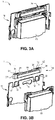
- Figures 3A and 3B show a third embodiment of the electric device 1 according to the invention. Again, only the difference with the electric device 1 of the first and second embodiment will be explained. It has to be understood that the other parts that are not described here anymore are the similar as for the electric device 1 described in the first embodiment and/or the second embodiment. According to the third embodiment, the elongated middle part 33 of the label carrier 30 may extend across the first support member 31 and the second support member 32.
- two transitional parts 37, 37' are provided between the first support member 31 and the elongated middle part 33, and two transitional parts 38, 38' are provided between the second support member 32 and the elongated middle part 33.
- two cut-outs 11, 11' are provided to accommodate the first transitional parts 37, 37' when mounting the label carrier 30 onto the mounting frame 10.
- two cut-outs 12, 12' are provided to accommodate the second transitional parts 38, 38' when mounting the label carrier 30 onto the mounting frame 10.
- the label carrier 30 may comprise a first slot 41 adjacent to the first support member 31 and a second slot 42 adjacent to the second support member 32.
- the first protrusion 13 of the mounting frame 10 fits into the first slot 41 and the second protrusion 14 of the mounting frame fits into the second slot 42.
Priority Applications (1)
| Application Number | Priority Date | Filing Date | Title |
|---|---|---|---|
| PL16173435T PL3104478T3 (pl) | 2015-06-10 | 2016-06-08 | Elektryczne urządzenie z etykietowym nośnikiem |
Applications Claiming Priority (1)
| Application Number | Priority Date | Filing Date | Title |
|---|---|---|---|
| BE2015/0164A BE1023177B1 (nl) | 2015-06-10 | 2015-06-10 | Elektrische inrichting met labeldrager |
Publications (2)
| Publication Number | Publication Date |
|---|---|
| EP3104478A1 true EP3104478A1 (de) | 2016-12-14 |
| EP3104478B1 EP3104478B1 (de) | 2018-01-24 |
Family
ID=54146881
Family Applications (1)
| Application Number | Title | Priority Date | Filing Date |
|---|---|---|---|
| EP16173435.5A Active EP3104478B1 (de) | 2015-06-10 | 2016-06-08 | Elektrische vorrichtung mit etikettenträger |
Country Status (6)
| Country | Link |
|---|---|
| EP (1) | EP3104478B1 (de) |
| BE (1) | BE1023177B1 (de) |
| DK (1) | DK3104478T3 (de) |
| HU (1) | HUE038604T2 (de) |
| NO (1) | NO3104478T3 (de) |
| PL (1) | PL3104478T3 (de) |
Citations (4)
| Publication number | Priority date | Publication date | Assignee | Title |
|---|---|---|---|---|
| DE8807214U1 (de) * | 1988-06-03 | 1988-07-21 | Bbc Brown Boveri Ag, 6800 Mannheim, De | |
| EP2383852A2 (de) | 2010-04-27 | 2011-11-02 | Berker GmbH & Co. KG | Elektrisches Installationsgerät |
| EP2393175A1 (de) * | 2010-06-02 | 2011-12-07 | GIRA GIERSIEPEN GmbH & Co. KG | Beschriftungsträger für ein Elektro-Installationsgerät |
| DE102013100909B3 (de) | 2013-01-30 | 2014-01-02 | Albrecht Jung Gmbh & Co Kg | Elektrisches Installationsgerät |
-
2015
- 2015-06-10 BE BE2015/0164A patent/BE1023177B1/nl not_active IP Right Cessation
-
2016
- 2016-06-08 EP EP16173435.5A patent/EP3104478B1/de active Active
- 2016-06-08 NO NO16173435A patent/NO3104478T3/no unknown
- 2016-06-08 PL PL16173435T patent/PL3104478T3/pl unknown
- 2016-06-08 DK DK16173435.5T patent/DK3104478T3/en active
- 2016-06-08 HU HUE16173435A patent/HUE038604T2/hu unknown
Patent Citations (4)
| Publication number | Priority date | Publication date | Assignee | Title |
|---|---|---|---|---|
| DE8807214U1 (de) * | 1988-06-03 | 1988-07-21 | Bbc Brown Boveri Ag, 6800 Mannheim, De | |
| EP2383852A2 (de) | 2010-04-27 | 2011-11-02 | Berker GmbH & Co. KG | Elektrisches Installationsgerät |
| EP2393175A1 (de) * | 2010-06-02 | 2011-12-07 | GIRA GIERSIEPEN GmbH & Co. KG | Beschriftungsträger für ein Elektro-Installationsgerät |
| DE102013100909B3 (de) | 2013-01-30 | 2014-01-02 | Albrecht Jung Gmbh & Co Kg | Elektrisches Installationsgerät |
Also Published As
| Publication number | Publication date |
|---|---|
| DK3104478T3 (en) | 2018-02-26 |
| PL3104478T3 (pl) | 2018-04-30 |
| EP3104478B1 (de) | 2018-01-24 |
| HUE038604T2 (hu) | 2018-10-29 |
| NO3104478T3 (de) | 2018-06-23 |
| BE1023177B1 (nl) | 2016-12-12 |
| BE1023177A1 (nl) | 2016-12-12 |
Similar Documents
| Publication | Publication Date | Title |
|---|---|---|
| US10107978B2 (en) | Optical module and assembly method thereof | |
| US7572975B2 (en) | Electrical box with mounting system | |
| EP3396235A1 (de) | Downlight-fixierstruktur | |
| CN112351636A (zh) | 风扇固定结构及采用该风扇固定结构的机箱 | |
| US20170311740A1 (en) | Mounting dock for a display frame | |
| US7565760B2 (en) | Board, especially an information board | |
| US6410851B1 (en) | Mounting system for electrical wiring boxes | |
| JP2007180500A (ja) | 電気デバイスのための多機能取付けブラケット | |
| EP3104478A1 (de) | Elektrische vorrichtung mit etikettenträger | |
| US9656614B2 (en) | Trim assemblies for mounting working subassemblies | |
| US10666308B2 (en) | Communication-adapter mounting device | |
| JP4459843B2 (ja) | Rfリーダの取付構造 | |
| EP2458265B1 (de) | Beleuchtungsvorrichtungen mit Aussparungen und Abdeckung dafür | |
| EP3109960B1 (de) | Montageanordnung mit verbessertem montagegehäuse | |
| CN210801081U (zh) | 细长型微波感应器 | |
| KR20020075192A (ko) | 케이블 내장 고정구 | |
| CN210928370U (zh) | 外壳组件 | |
| CN211151016U (zh) | 一种电缆连接器组件 | |
| CN213734848U (zh) | 卡装结构及车门 | |
| CN217272867U (zh) | 一种具有磁吸卡扣组合结构塑胶壳体 | |
| CN110392505B (zh) | 电路板固定装置及电路板组件 | |
| CN209371166U (zh) | 灯座 | |
| JPS582068Y2 (ja) | 電源コ−ド取付装置 | |
| ES1216639U (es) | Soporte para etiquetas electrónicas, aplicable a bases metálicas | |
| KR200430040Y1 (ko) | 차량용 감시카메라 하우징 구조 |
Legal Events
| Date | Code | Title | Description |
|---|---|---|---|
| PUAI | Public reference made under article 153(3) epc to a published international application that has entered the european phase |
Free format text: ORIGINAL CODE: 0009012 |
|
| AK | Designated contracting states |
Kind code of ref document: A1 Designated state(s): AL AT BE BG CH CY CZ DE DK EE ES FI FR GB GR HR HU IE IS IT LI LT LU LV MC MK MT NL NO PL PT RO RS SE SI SK SM TR |
|
| AX | Request for extension of the european patent |
Extension state: BA ME |
|
| 17P | Request for examination filed |
Effective date: 20170519 |
|
| RBV | Designated contracting states (corrected) |
Designated state(s): AL AT BE BG CH CY CZ DE DK EE ES FI FR GB GR HR HU IE IS IT LI LT LU LV MC MK MT NL NO PL PT RO RS SE SI SK SM TR |
|
| GRAP | Despatch of communication of intention to grant a patent |
Free format text: ORIGINAL CODE: EPIDOSNIGR1 |
|
| INTG | Intention to grant announced |
Effective date: 20170809 |
|
| GRAS | Grant fee paid |
Free format text: ORIGINAL CODE: EPIDOSNIGR3 |
|
| GRAA | (expected) grant |
Free format text: ORIGINAL CODE: 0009210 |
|
| AK | Designated contracting states |
Kind code of ref document: B1 Designated state(s): AL AT BE BG CH CY CZ DE DK EE ES FI FR GB GR HR HU IE IS IT LI LT LU LV MC MK MT NL NO PL PT RO RS SE SI SK SM TR |
|
| REG | Reference to a national code |
Ref country code: GB Ref legal event code: FG4D |
|
| REG | Reference to a national code |
Ref country code: CH Ref legal event code: EP |
|
| REG | Reference to a national code |
Ref country code: AT Ref legal event code: REF Ref document number: 966281 Country of ref document: AT Kind code of ref document: T Effective date: 20180215 Ref country code: CH Ref legal event code: NV Representative=s name: MICHELI AND CIE SA, CH |
|
| REG | Reference to a national code |
Ref country code: IE Ref legal event code: FG4D |
|
| REG | Reference to a national code |
Ref country code: DK Ref legal event code: T3 Effective date: 20180219 |
|
| REG | Reference to a national code |
Ref country code: NL Ref legal event code: FP |
|
| REG | Reference to a national code |
Ref country code: DE Ref legal event code: R096 Ref document number: 602016001442 Country of ref document: DE |
|
| REG | Reference to a national code |
Ref country code: SE Ref legal event code: TRGR |
|
| REG | Reference to a national code |
Ref country code: NO Ref legal event code: T2 Effective date: 20180124 |
|
| REG | Reference to a national code |
Ref country code: SK Ref legal event code: T3 Ref document number: E 26589 Country of ref document: SK |
|
| REG | Reference to a national code |
Ref country code: LT Ref legal event code: MG4D |
|
| REG | Reference to a national code |
Ref country code: AT Ref legal event code: MK05 Ref document number: 966281 Country of ref document: AT Kind code of ref document: T Effective date: 20180124 |
|
| REG | Reference to a national code |
Ref country code: FR Ref legal event code: PLFP Year of fee payment: 3 |
|
| PG25 | Lapsed in a contracting state [announced via postgrant information from national office to epo] |
Ref country code: CY Free format text: LAPSE BECAUSE OF FAILURE TO SUBMIT A TRANSLATION OF THE DESCRIPTION OR TO PAY THE FEE WITHIN THE PRESCRIBED TIME-LIMIT Effective date: 20180124 Ref country code: HR Free format text: LAPSE BECAUSE OF FAILURE TO SUBMIT A TRANSLATION OF THE DESCRIPTION OR TO PAY THE FEE WITHIN THE PRESCRIBED TIME-LIMIT Effective date: 20180124 Ref country code: LT Free format text: LAPSE BECAUSE OF FAILURE TO SUBMIT A TRANSLATION OF THE DESCRIPTION OR TO PAY THE FEE WITHIN THE PRESCRIBED TIME-LIMIT Effective date: 20180124 Ref country code: ES Free format text: LAPSE BECAUSE OF FAILURE TO SUBMIT A TRANSLATION OF THE DESCRIPTION OR TO PAY THE FEE WITHIN THE PRESCRIBED TIME-LIMIT Effective date: 20180124 Ref country code: FI Free format text: LAPSE BECAUSE OF FAILURE TO SUBMIT A TRANSLATION OF THE DESCRIPTION OR TO PAY THE FEE WITHIN THE PRESCRIBED TIME-LIMIT Effective date: 20180124 |
|
| PG25 | Lapsed in a contracting state [announced via postgrant information from national office to epo] |
Ref country code: LV Free format text: LAPSE BECAUSE OF FAILURE TO SUBMIT A TRANSLATION OF THE DESCRIPTION OR TO PAY THE FEE WITHIN THE PRESCRIBED TIME-LIMIT Effective date: 20180124 Ref country code: AT Free format text: LAPSE BECAUSE OF FAILURE TO SUBMIT A TRANSLATION OF THE DESCRIPTION OR TO PAY THE FEE WITHIN THE PRESCRIBED TIME-LIMIT Effective date: 20180124 Ref country code: BG Free format text: LAPSE BECAUSE OF FAILURE TO SUBMIT A TRANSLATION OF THE DESCRIPTION OR TO PAY THE FEE WITHIN THE PRESCRIBED TIME-LIMIT Effective date: 20180424 Ref country code: IS Free format text: LAPSE BECAUSE OF FAILURE TO SUBMIT A TRANSLATION OF THE DESCRIPTION OR TO PAY THE FEE WITHIN THE PRESCRIBED TIME-LIMIT Effective date: 20180524 Ref country code: GR Free format text: LAPSE BECAUSE OF FAILURE TO SUBMIT A TRANSLATION OF THE DESCRIPTION OR TO PAY THE FEE WITHIN THE PRESCRIBED TIME-LIMIT Effective date: 20180425 Ref country code: RS Free format text: LAPSE BECAUSE OF FAILURE TO SUBMIT A TRANSLATION OF THE DESCRIPTION OR TO PAY THE FEE WITHIN THE PRESCRIBED TIME-LIMIT Effective date: 20180124 |
|
| REG | Reference to a national code |
Ref country code: DE Ref legal event code: R097 Ref document number: 602016001442 Country of ref document: DE |
|
| REG | Reference to a national code |
Ref country code: HU Ref legal event code: AG4A Ref document number: E038604 Country of ref document: HU |
|
| PG25 | Lapsed in a contracting state [announced via postgrant information from national office to epo] |
Ref country code: AL Free format text: LAPSE BECAUSE OF FAILURE TO SUBMIT A TRANSLATION OF THE DESCRIPTION OR TO PAY THE FEE WITHIN THE PRESCRIBED TIME-LIMIT Effective date: 20180124 Ref country code: EE Free format text: LAPSE BECAUSE OF FAILURE TO SUBMIT A TRANSLATION OF THE DESCRIPTION OR TO PAY THE FEE WITHIN THE PRESCRIBED TIME-LIMIT Effective date: 20180124 Ref country code: IT Free format text: LAPSE BECAUSE OF FAILURE TO SUBMIT A TRANSLATION OF THE DESCRIPTION OR TO PAY THE FEE WITHIN THE PRESCRIBED TIME-LIMIT Effective date: 20180124 |
|
| PG25 | Lapsed in a contracting state [announced via postgrant information from national office to epo] |
Ref country code: SM Free format text: LAPSE BECAUSE OF FAILURE TO SUBMIT A TRANSLATION OF THE DESCRIPTION OR TO PAY THE FEE WITHIN THE PRESCRIBED TIME-LIMIT Effective date: 20180124 |
|
| PLBE | No opposition filed within time limit |
Free format text: ORIGINAL CODE: 0009261 |
|
| STAA | Information on the status of an ep patent application or granted ep patent |
Free format text: STATUS: NO OPPOSITION FILED WITHIN TIME LIMIT |
|
| 26N | No opposition filed |
Effective date: 20181025 |
|
| PG25 | Lapsed in a contracting state [announced via postgrant information from national office to epo] |
Ref country code: SI Free format text: LAPSE BECAUSE OF FAILURE TO SUBMIT A TRANSLATION OF THE DESCRIPTION OR TO PAY THE FEE WITHIN THE PRESCRIBED TIME-LIMIT Effective date: 20180124 |
|
| REG | Reference to a national code |
Ref country code: IE Ref legal event code: MM4A |
|
| PG25 | Lapsed in a contracting state [announced via postgrant information from national office to epo] |
Ref country code: LU Free format text: LAPSE BECAUSE OF NON-PAYMENT OF DUE FEES Effective date: 20180608 Ref country code: MC Free format text: LAPSE BECAUSE OF FAILURE TO SUBMIT A TRANSLATION OF THE DESCRIPTION OR TO PAY THE FEE WITHIN THE PRESCRIBED TIME-LIMIT Effective date: 20180124 |
|
| PG25 | Lapsed in a contracting state [announced via postgrant information from national office to epo] |
Ref country code: IE Free format text: LAPSE BECAUSE OF NON-PAYMENT OF DUE FEES Effective date: 20180608 |
|
| PG25 | Lapsed in a contracting state [announced via postgrant information from national office to epo] |
Ref country code: MT Free format text: LAPSE BECAUSE OF NON-PAYMENT OF DUE FEES Effective date: 20180608 |
|
| PG25 | Lapsed in a contracting state [announced via postgrant information from national office to epo] |
Ref country code: TR Free format text: LAPSE BECAUSE OF FAILURE TO SUBMIT A TRANSLATION OF THE DESCRIPTION OR TO PAY THE FEE WITHIN THE PRESCRIBED TIME-LIMIT Effective date: 20180124 |
|
| PG25 | Lapsed in a contracting state [announced via postgrant information from national office to epo] |
Ref country code: PT Free format text: LAPSE BECAUSE OF FAILURE TO SUBMIT A TRANSLATION OF THE DESCRIPTION OR TO PAY THE FEE WITHIN THE PRESCRIBED TIME-LIMIT Effective date: 20180124 |
|
| PG25 | Lapsed in a contracting state [announced via postgrant information from national office to epo] |
Ref country code: RO Free format text: LAPSE BECAUSE OF FAILURE TO SUBMIT A TRANSLATION OF THE DESCRIPTION OR TO PAY THE FEE WITHIN THE PRESCRIBED TIME-LIMIT Effective date: 20180124 Ref country code: MK Free format text: LAPSE BECAUSE OF NON-PAYMENT OF DUE FEES Effective date: 20180124 |
|
| PGFP | Annual fee paid to national office [announced via postgrant information from national office to epo] |
Ref country code: CZ Payment date: 20200605 Year of fee payment: 5 |
|
| PGFP | Annual fee paid to national office [announced via postgrant information from national office to epo] |
Ref country code: HU Payment date: 20200722 Year of fee payment: 5 |
|
| PG25 | Lapsed in a contracting state [announced via postgrant information from national office to epo] |
Ref country code: CZ Free format text: LAPSE BECAUSE OF NON-PAYMENT OF DUE FEES Effective date: 20210608 |
|
| PG25 | Lapsed in a contracting state [announced via postgrant information from national office to epo] |
Ref country code: HU Free format text: LAPSE BECAUSE OF NON-PAYMENT OF DUE FEES Effective date: 20210609 |
|
| P01 | Opt-out of the competence of the unified patent court (upc) registered |
Effective date: 20230526 |
|
| PGFP | Annual fee paid to national office [announced via postgrant information from national office to epo] |
Ref country code: NO Payment date: 20230622 Year of fee payment: 8 Ref country code: DK Payment date: 20230622 Year of fee payment: 8 Ref country code: DE Payment date: 20230620 Year of fee payment: 8 Ref country code: NL Payment date: 20230620 Year of fee payment: 8 Ref country code: FR Payment date: 20230628 Year of fee payment: 8 |
|
| PGFP | Annual fee paid to national office [announced via postgrant information from national office to epo] |
Ref country code: SK Payment date: 20230530 Year of fee payment: 8 Ref country code: SE Payment date: 20230620 Year of fee payment: 8 Ref country code: PL Payment date: 20230526 Year of fee payment: 8 |
|
| PGFP | Annual fee paid to national office [announced via postgrant information from national office to epo] |
Ref country code: BE Payment date: 20230620 Year of fee payment: 8 |
|
| PGFP | Annual fee paid to national office [announced via postgrant information from national office to epo] |
Ref country code: GB Payment date: 20230622 Year of fee payment: 8 Ref country code: CH Payment date: 20230702 Year of fee payment: 8 |