EP3104401A1 - Purge device and purge method - Google Patents
Purge device and purge method Download PDFInfo
- Publication number
- EP3104401A1 EP3104401A1 EP14881475.9A EP14881475A EP3104401A1 EP 3104401 A1 EP3104401 A1 EP 3104401A1 EP 14881475 A EP14881475 A EP 14881475A EP 3104401 A1 EP3104401 A1 EP 3104401A1
- Authority
- EP
- European Patent Office
- Prior art keywords
- flow rate
- storage container
- purging
- purge
- purge gas
- Prior art date
- Legal status (The legal status is an assumption and is not a legal conclusion. Google has not performed a legal analysis and makes no representation as to the accuracy of the status listed.)
- Granted
Links
Images




Classifications
-
- H—ELECTRICITY
- H10—SEMICONDUCTOR DEVICES; ELECTRIC SOLID-STATE DEVICES NOT OTHERWISE PROVIDED FOR
- H10P—GENERIC PROCESSES OR APPARATUS FOR THE MANUFACTURE OR TREATMENT OF DEVICES COVERED BY CLASS H10
- H10P72/00—Handling or holding of wafers, substrates or devices during manufacture or treatment thereof
- H10P72/10—Handling or holding of wafers, substrates or devices during manufacture or treatment thereof using carriers specially adapted therefor, e.g. front opening unified pods [FOUP]
- H10P72/19—Handling or holding of wafers, substrates or devices during manufacture or treatment thereof using carriers specially adapted therefor, e.g. front opening unified pods [FOUP] closed carriers
- H10P72/1924—Handling or holding of wafers, substrates or devices during manufacture or treatment thereof using carriers specially adapted therefor, e.g. front opening unified pods [FOUP] closed carriers characterised by atmosphere control
- H10P72/1926—Handling or holding of wafers, substrates or devices during manufacture or treatment thereof using carriers specially adapted therefor, e.g. front opening unified pods [FOUP] closed carriers characterised by atmosphere control characterised by the presence of atmosphere modifying elements inside or attached to the closed carrier
-
- B—PERFORMING OPERATIONS; TRANSPORTING
- B08—CLEANING
- B08B—CLEANING IN GENERAL; PREVENTION OF FOULING IN GENERAL
- B08B5/00—Cleaning by methods involving the use of air flow or gas flow
- B08B5/04—Cleaning by suction, with or without auxiliary action
-
- B—PERFORMING OPERATIONS; TRANSPORTING
- B08—CLEANING
- B08B—CLEANING IN GENERAL; PREVENTION OF FOULING IN GENERAL
- B08B9/00—Cleaning hollow articles by methods or apparatus specially adapted thereto
- B08B9/08—Cleaning containers, e.g. tanks
-
- H—ELECTRICITY
- H10—SEMICONDUCTOR DEVICES; ELECTRIC SOLID-STATE DEVICES NOT OTHERWISE PROVIDED FOR
- H10P—GENERIC PROCESSES OR APPARATUS FOR THE MANUFACTURE OR TREATMENT OF DEVICES COVERED BY CLASS H10
- H10P72/00—Handling or holding of wafers, substrates or devices during manufacture or treatment thereof
- H10P72/06—Apparatus for monitoring, sorting, marking, testing or measuring
- H10P72/0604—Process monitoring, e.g. flow or thickness monitoring
-
- H—ELECTRICITY
- H10—SEMICONDUCTOR DEVICES; ELECTRIC SOLID-STATE DEVICES NOT OTHERWISE PROVIDED FOR
- H10P—GENERIC PROCESSES OR APPARATUS FOR THE MANUFACTURE OR TREATMENT OF DEVICES COVERED BY CLASS H10
- H10P72/00—Handling or holding of wafers, substrates or devices during manufacture or treatment thereof
- H10P72/30—Handling or holding of wafers, substrates or devices during manufacture or treatment thereof for conveying, e.g. between different workstations
- H10P72/34—Handling or holding of wafers, substrates or devices during manufacture or treatment thereof for conveying, e.g. between different workstations the wafers being stored in a carrier, involving loading and unloading
- H10P72/3404—Storage means
-
- H—ELECTRICITY
- H10—SEMICONDUCTOR DEVICES; ELECTRIC SOLID-STATE DEVICES NOT OTHERWISE PROVIDED FOR
- H10P—GENERIC PROCESSES OR APPARATUS FOR THE MANUFACTURE OR TREATMENT OF DEVICES COVERED BY CLASS H10
- H10P74/00—Testing or measuring during manufacture or treatment of wafers, substrates or devices
- H10P74/20—Testing or measuring during manufacture or treatment of wafers, substrates or devices characterised by the properties tested or measured, e.g. structural or electrical properties
- H10P74/203—Structural properties, e.g. testing or measuring thicknesses, line widths, warpage, bond strengths or physical defects
-
- H—ELECTRICITY
- H10—SEMICONDUCTOR DEVICES; ELECTRIC SOLID-STATE DEVICES NOT OTHERWISE PROVIDED FOR
- H10P—GENERIC PROCESSES OR APPARATUS FOR THE MANUFACTURE OR TREATMENT OF DEVICES COVERED BY CLASS H10
- H10P74/00—Testing or measuring during manufacture or treatment of wafers, substrates or devices
- H10P74/23—Testing or measuring during manufacture or treatment of wafers, substrates or devices characterised by multiple measurements, corrections, marking or sorting processes
- H10P74/235—Testing or measuring during manufacture or treatment of wafers, substrates or devices characterised by multiple measurements, corrections, marking or sorting processes comprising optical enhancement of defects or not-directly-visible states
-
- H—ELECTRICITY
- H10—SEMICONDUCTOR DEVICES; ELECTRIC SOLID-STATE DEVICES NOT OTHERWISE PROVIDED FOR
- H10W—GENERIC PACKAGES, INTERCONNECTIONS, CONNECTORS OR OTHER CONSTRUCTIONAL DETAILS OF DEVICES COVERED BY CLASS H10
- H10W72/00—Interconnections or connectors in packages
- H10W72/071—Connecting or disconnecting
- H10W72/072—Connecting or disconnecting of bump connectors
- H10W72/07231—Techniques
-
- H—ELECTRICITY
- H10—SEMICONDUCTOR DEVICES; ELECTRIC SOLID-STATE DEVICES NOT OTHERWISE PROVIDED FOR
- H10P—GENERIC PROCESSES OR APPARATUS FOR THE MANUFACTURE OR TREATMENT OF DEVICES COVERED BY CLASS H10
- H10P72/00—Handling or holding of wafers, substrates or devices during manufacture or treatment thereof
- H10P72/10—Handling or holding of wafers, substrates or devices during manufacture or treatment thereof using carriers specially adapted therefor, e.g. front opening unified pods [FOUP]
- H10P72/19—Handling or holding of wafers, substrates or devices during manufacture or treatment thereof using carriers specially adapted therefor, e.g. front opening unified pods [FOUP] closed carriers
- H10P72/1908—Handling or holding of wafers, substrates or devices during manufacture or treatment thereof using carriers specially adapted therefor, e.g. front opening unified pods [FOUP] closed carriers specially adapted for containing substrates other than wafers
Definitions
- the present invention relates to a purge apparatus and a purge method of purging the inside of a storage container in which a product is stored, with a purge gas, such as an inert gas or purified dry air.
- a purge gas such as an inert gas or purified dry air.
- a purge apparatus which keeps cleanliness by introducing a purge gas (purging) to the inside of a storage container in which a product, such as a semiconductor wafer or a glass substrate, is stored.
- a purge apparatus the flow rate of the purge gas supplied to the storage container may be controlled.
- a failure of a control circuit in the purge apparatus or a problem occurred in a supply channel of purge gas may prevent purge gas from being actually supplied into the storage container at a desired flow rate and may result in unsatisfactory purging.
- Patent Literature 1 Japanese Patent No. 4670808
- Patent Literature 1 Japanese Patent No. 4670808 discloses a technique for measuring the flow rate of purge gas supplied to the inside of a storage container. With the measurement container described in Japanese Patent No. 4670808 , discloses a technique for measuring the flow rate of purge gas supplied to the inside of a storage container. With the measurement container described in Japanese Patent No. 4670808 .
- Patent Literature 1 a dedicated flow rate-measuring unit is placed on the purge apparatus to measure the flow rate of the purge gas supplied from the purge apparatus, so that whether satisfactory purging is performed can be determined. However, it is sometimes desired that whether satisfactory purging is being performed should be determined during a process of actually supplying purge gas to a storage container to be purged.
- a purge apparatus purges an inside of a storage container in which a product is stored, with a purge gas.
- the purge apparatus includes a discharge pipe configured to connect to a discharge port of the storage container to discharge the purge gas inside the storage container, a meter configured to measure an exhaust flow rate that is a flow rate of the purge gas flowing through the discharge pipe when the purging is carried out, and a determination unit configured to determine whether the purging is satisfactory, based on the exhaust flow rate measured by the meter.
- the meter for measuring the flow rate of purge gas flowing through the discharge pipe is provided not in the measuring unit placed on the purge apparatus but in the purge apparatus side.
- the exhaust flow rate can be measured when purge gas is supplied to the storage container in a state in which the storage container to be purged is actually placed on the purge apparatus, and whether purging is satisfactory can be determined based on the measured exhaust flow rate. Accordingly, whether satisfactory purging is being performed can be determined during a process of actually supplying purge gas to the storage container.
- the inventors of the subject application have conducted elaborate studies to find that the exhaust efficiency is greatly affected by the hermeticity of the storage container. That is, when the flow rate of purge gas supplied to the storage container is greater than a predetermined flow rate (when the internal pressure of the storage container is greater than a predetermined pressure), the purge gas leaks from a portion other than the discharge port of the storage container (for example, between the cover and the body of the storage container) and the flow rate of exhaust discharged from the discharge pipe tends to be saturated. In other words, it has been found that the exhaust flow rate substantially proportional to the supply flow rate is obtained up to the predetermined flow rate at which purge gas leaks from a portion other than the discharge port of the storage container.
- the purge apparatus may further include a flow rate control unit configured to switch between a first mode in which the purging is carried out by supplying the purge gas to the storage container at a first flow rate and a second mode in which the purging is carried out by supplying the purge gas to the storage container at a second flow rate.
- the meter may measure the exhaust flow rate in the first mode, and the determination unit may determine whether the purging is satisfactory, based on the exhaust flow rate measured in the first mode.
- the first flow rate is a flow rate up to a predetermined flow rate, in the storage container in which the purge gas leaks from a portion other than the discharge port of the storage container when the flow rate of the purge gas supplied to the storage container is greater than the predetermined flow rate.
- the second flow rate is a flow rate greater than the first flow rate.
- the flow rate control unit may start the purging in the second mode and thereafter switch to the first mode.
- the meter may measure the exhaust flow rate in the first mode.
- the determination unit may determine whether the purging is satisfactory, based on the exhaust flow rate measured in the first mode.
- Such a purge apparatus can initially supply purge gas to the storage container at a relatively large flow rate thereby to clean the inside of the storage container early. This can reduce the possibility that the product is contaminated.
- a purge method is a method of purging an inside of a storage container in which a product is stored, with a purge gas.
- the purge method includes: connecting a discharge pipe to a discharge port of the storage container, the discharge pipe being capable of discharging the purge gas inside the storage container; measuring an exhaust flow rate that is a flow rate of the purge gas flowing through the discharge pipe when the purging is carried out; and determining whether the purging is satisfactory, based on the measured exhaust flow rate.
- an exhaust flow rate that is a flow rate of the purge gas flowing through the discharge pipe when the purging is carried out by supplying the purge gas to the storage container at a first flow rate may be measured. Whether the purging is satisfactory may be determined based on the measured exhaust flow rate.
- the first flow rate is a flow rate up to a predetermined flow rate, in the storage container in which the purge gas leaks from a portion other than the discharge port of the storage container when the flow rate of the purge gas supplied to the storage container is greater than the predetermined flow rate.
- a second flow rate is a flow rate greater than the first flow rate.
- whether satisfactory purging is being performed can be determined during a process of actually supplying purge gas to a storage container.
- the purge apparatus 30 is an apparatus for purging the inside of a storage container 50, such as a front opening unified pod (FOUP), in which a product, such as a semiconductor wafer or a glass substrate, is stored, with a purge gas.
- a purge gas as used herein include inert gases and purified dry air.
- the purge apparatus 30 is disposed, for example, in a purge stocker 1 for keeping a storage container 50 in which a product is stored. As shown in FIG. 1 and FIG. 2 , the purge stocker 1 is provided in, for example, a clean room 100.
- the purge stocker 1 provided in such a clean room 100 includes a partition 3, fan filter units (FFUs) 5, racks 7, a crane 9, an exhaust port 15A, an overhead hoist transfer (OHT) port 21, and a manual port 23.
- FFUs fan filter units
- racks 7 racks 7
- crane 9 an exhaust port 15A
- OHT overhead hoist transfer
- the partition 3 is a part that partitions (defines) a region above a floor 100A, and a storage area 1A is formed inside the partition 3.
- a plurality of FFUs 5 are provided along a predetermined direction on the ceiling of a space separated by the partition 3, that is, above the storage area 1A.
- the FFUs 5 suck the purified air from the outside of the storage area 1A to the inside of the storage area 1A to blow the purified air downward of the storage area 1 A.
- the exhaust port 15A is a part provided near the bottom of the storage area 1A to discharge gas including purge gas from the inside of the storage area 1A to the outside of the storage area 1A.
- the gas including purge gas is discharged from the storage area 1A by the exhaust fan 15.
- the racks 7 are parts for keeping storage containers 50 and are provided in multiple rows (here, two rows) in the inside of the storage area 1A. Each rack 7 extends in a predetermined direction X, and the two rows of racks 7, 7 are disposed to be opposed to each other in the depth direction Y. Each rack 7 has a plurality of storage shelves 7A on which storage containers 50 are placed and kept, along the predetermined direction X and the vertical direction Z.
- the crane 9 is a part for loading and unloading storage containers 50 into/from the storage shelves 7A and is disposed in a region sandwiched between the racks 7 and 7 opposed to each other.
- the crane 9 can run on a transport rail (not shown) disposed on the floor along the direction X in which the racks 7 extend, to move along the direction X in which the racks 7 extend.
- the crane 9 has a stage 9A that can be lifted and lowered along a guide rail 9B so that storage containers 50 can be loaded into and unloaded from a plurality of storage shelves 7A provided in the vertical direction.
- a storage container 50 is loaded into and unloaded from the purge stocker 1 through the OHT port 21 and the manual port 23.
- the OHT port 21 is a part for delivering a storage container 50 between the purge stocker 1 and a ceiling vehicle (OHT) 27 running on a transport rail 25 laid on the ceiling 100B and has a conveyor 21A for transferring a storage container 50.
- the manual port 23 is a part for delivering a storage container 50 between the operator and the purge stocker 1 and has a conveyor 23A for transferring a storage container 50.
- the storage shelf 7A of the rack 7 is provided with a purge apparatus 30 for purging the inside of the storage container 50 placed thereon with a purge gas (for example, nitrogen gas).
- the purge apparatus 30 is an apparatus for supplying and discharging a purge gas into the storage container 50 placed on the storage shelf 7A.
- the storage container 50 includes a body 51 and a cover 53 to form a casing.
- the storage container 50 has a sealed space 54 formed with the body 51 and the cover 53.
- the sealed space 54 accommodates a plurality of semiconductor wafers (not shown).
- the lower surface of the bottom 52 that is the bottom surface of the body 51 has discharge ports 56 near the right and left ends of the front end, and supply ports 55 at the right and left ends of the rear end, where the side on which the cover 53 is disposed is the front.
- the supply ports 55 each include a connection portion 52A and a communication portion 52C.
- the discharge ports 56 each include a connection portion 52B and a communication portion 52D.
- the connection portion 52A is configured to be connectable to the supply pipe 31 of the purge apparatus 30 described in details later.
- the connection portion 52B is configured to be connectable to the discharge pipe 33 of the purge apparatus 30.
- connection portions 52A, 52B have the communication portions 52C, 52D, respectively, having diameters equivalent to the inner diameters of the supply pipe 31 and discharge pipe 33.
- the communication portions 52C, 52D are holes that communicate the sealed space 54 with the outside of the storage container 50.
- the cover 53 is disposed at one face that is a side surface of the body 51.
- the cover 53 is provided with, for example, a latch mechanism 58.
- the latch mechanism 58 has a latch 58A and a cam 58B.
- the latch 58A is configured such that an end of the latch 58A on the side opposite to the cam 58B is put in and out by inserting a key (not shown) into an insertion hole 58C provided at the cam 58B and turning the key. This end of the latch 58A is then fitted into a fitting groove 51A provided in the body 51 on the surface facing the latch 58A, whereby the cover 53 is fixed to the body 51.
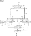
- FIG. 4 is a schematic configuration diagram showing a configuration of the purge apparatus 30.
- the purge apparatus 30 includes a supply pipe 31, a mass flow controller (MFC) 35, a purge gas source 37, a discharge pipe 33, a flowmeter (meter) 39, and a controller 40.
- MFC mass flow controller
- the front end of the supply pipe 31 has a nozzle configured to connect to the supply port 55 of the storage container to supply a purge gas to the storage container 50.
- the supply pipe 31 is brought into intimate contact with the connection portion 52A to be connected to the communication portion 52C.
- the MFC 35 is equipment that measures the mass flow rate of the purge gas flowing through the supply pipe 31 and performs flow rate control.
- the purge gas source 37 is a tank for storing a purge gas.
- the front end of the discharge pipe 33 has a nozzle configured to connect to the discharge port 56 of the storage container 50 to suck the purge gas in the inside 54 of the storage container 50 and discharge the purge gas in the inside 54 of the storage container 50.
- the discharge pipe 33 is brought into intimate contact with the connection portion 52B to be connected to the communication portion 52D.
- the flowmeter 39 is equipment that measures the flow rate of the purge gas flowing through the discharge pipe 33.
- the controller 40 is a part that controls a variety of purging in the purge apparatus 30 and is, for example, an electronic control unit including a central processing unit (CPU), a read only memory (ROM), and a random access memory (RAM). As shown in FIG. 4 , the controller 40 has a flow rate control unit 41 and a determination unit 43 serving as conceptual units that execute a variety of control processes in the purge apparatus 30. The functions executed by such conceptual units are executed under the control of the CPU or the like.
- CPU central processing unit
- ROM read only memory
- RAM random access memory
- the flow rate control unit 41 is a unit that switches between a first mode in which purging is carried out by supplying purge gas to the storage container 50 at a first flow rate and a second mode in which purging is carried out by supplying purge gas to the storage container 50 at a second flow rate.
- the "first flow rate” refers to a flow rate up to a predetermined flow rate, in the storage container 50 in which purge gas leaks from a portion other than the discharge port of the storage container 50 (for example, as shown in FIG. 3(A) and FIG. 3(B) , the portion between the body 51 and the cover 53) when the flow rate of the purge gas supplied to the storage container 50 is greater than the predetermined flow rate.
- the "second flow rate” refers to the flow rate greater than the first flow rate.
- the determination unit 43 is a unit that determines whether purging is satisfactory, based on the exhaust flow rate measured by the flowmeter 39. Specifically, the determination unit 43 determines whether purging is satisfactory, based on a supply flow rate Fs by the MFC 35 when controlled with the first flow rate (the first mode) by the flow rate control unit 41, and an exhaust flow rate Fe measured by the flowmeter 39 disposed at the discharge pipe 33. For example, when the exhaust flow rate Fe is smaller than the supply flow rate Fs by a predetermined amount or more, it can be determined that purging is not being performed satisfactorily.
- the determination unit 43 may determine whether purging is satisfactory, considering the flow rate transfer ratios in the not-shown nozzle for injecting purge gas from the front end of the supply pipe 31 to the storage container 50 and the not-shown nozzle for injecting purge gas from the storage container 50 to the discharge pipe 33.
- the flow rate transfer ratio of the nozzle for injecting purge gas to the storage container 50 in the supply pipe 31 is defined as A
- the flow rate transfer ratio of the nozzle for injecting purge gas to the discharge pipe 33 in the storage container 50 is defined as B
- the exhaust flow rate Fe is smaller than a value obtained by multiplying the supply flow rate Fs by A and B (Fs x A x B), by a predetermined amount or more, it may be determined that purging is not being performed satisfactorily.
- the flow rate transfer ratios A and B can be set as appropriate according to the characteristics of the nozzles. If the nozzles are made of metal, a value of 0.70 to 0.95 may be set as the flow rate transfer ratios A and B. If the nozzles are elastic, a value of 0.90 to 1.00 may be set as the flow rate transfer ratios A and B.
- the flow rate control unit 41 starts supply of a purge gas to the storage container 50 (purging). As shown in FIG. 5 , the flow rate control unit 41 starts a mode of supplying purge gas at a flow rate f2 that is the second flow rate (the second mode) and continues the second mode until time t1.
- the flow rate control unit 41 thereafter switches to a mode of supplying purge gas at a flow rate f1 that is the first flow rate (the first mode) in order to determine whether the purging is satisfactory, and continues the first mode until time t2.
- the determination unit 43 determines whether the purging is satisfactory by the method as illustrated above at this time (the first mode).
- the flow rate control unit 41 thereafter switches again to the mode of supplying purge gas at the flow rate f2 that is the second flow rate (the second mode), and continues the mode for a predetermined time or until the storage container 50 is moved from the storage shelf 7A.
- the result of the determination by the determination unit 43 as to whether the purging is satisfactory may be indicated to the operator, for example, by display appearing on a not-shown display (not shown) of the purge apparatus 30, by producing warning sound, or by transmitting information of the result to another terminal.
- the flowmeter 39 for measuring the flow rate of the purge gas flowing through the discharge pipe 33 is provided not in the measuring unit placed on the purge apparatus 30 but in the purge apparatus 30.
- the exhaust flow rate can be measured when purge gas is supplied to the storage container 50 in a state in which the storage container 50 to be purged is actually placed on the purge apparatus 30, and whether purging is satisfactory can be determined based on the measured exhaust flow rate. Accordingly, whether satisfactory purging is being performed can be determined during a process of actually supplying purge gas to the storage container 50.
- the inventors of the subject application have conducted elaborate studies to find that the exhaust efficiency is greatly affected by the hermeticity of the storage container 50. That is, as shown in FIG 6 , when the flow rate of purge gas supplied to the storage container 50 is greater than a predetermined flow rate F1 (when the internal pressure of the storage container 50 is greater than a predetermined pressure P1), the purge gas leaks from between the cover 53 and the body 51 of the storage container 50 and the flow rate of exhaust discharged from the discharge pipe 33 tends to be saturated. In other words, it has been found that the exhaust flow rate substantially proportional to the supply flow rate is obtained up to the predetermined flow rate F1 (0 to F1) at which purge gas leaks from between the cover 53 and the body 51 of the storage container 50.
- the purge apparatus 30 configured as described above is switchable between the first mode in which purging is carried out by supplying purge gas to the storage container 50 at a first flow rate f1 and the second mode in which purging is carried out by supplying purge gas to the storage container 50 at a second flow rate f2, where the first flow rate f1 is a supply flow rate up to a predetermined flow rate F1, in the storage container 50 in which purge gas leaks from between the cover 53 and the body 51 of the storage container 50 when the flow rate of the purge gas supplied to the storage container 50 is greater than the predetermined flow rate F1, as shown in FIG. 6 , and the second flow rate f2 is a flow rate greater than the first flow rate.
- the purge apparatus 30 measures the exhaust flow rate in the first mode and determines whether purging is satisfactory based on the exhaust flow rate measured in the first mode.
- This purge apparatus 30 determines whether purging is satisfactory, based on the supply flow rate that is the first flow rate f1 at which the exhaust flow rate is substantially proportional to the supply flow rate, and the exhaust flow rate obtained when purging is performed at the first flow rate f1. Thus, whether purging is satisfactory can be determined based on the supply flow rate and the exhaust flow rate substantially proportional to each other, thereby enabling an accurate determination.
- the purge apparatus 30 configured as described above starts purging in the second mode, thereafter switches to the first mode, measures the exhaust flow rate in the first mode, and determines whether purging is satisfactory, based on the exhaust flow rate measured in the first mode.
- purge gas is initially supplied to the storage container 50 at a relatively large flow rate, so that the inside of the storage container 50 can be cleaned early. This can reduce the possibility that the product is contaminated.
- the purge apparatus 30 may start purging in the first mode, determine whether purging is satisfactory based on the exhaust flow rate measured in the first mode, and then switch to the second mode to continue the purging. In this case, whether purging is satisfactory can be determined at an early stage in the purging, so that if a problem arises, measures can be taken early.
- the purge apparatus 30 may start purging in the second mode, switch to the first mode at the last stage in which the purging is terminated, determine whether the purging is satisfactory based on the exhaust flow rate measured in the first mode, and terminate the purging as it is.
- purge gas is initially supplied to the storage container 50 at a relatively large flow rate, so that the inside of the storage container 50 can be cleaned early. This control is effective when whether purging has been performed satisfactorily is confirmed at any timing.
- the purge apparatus 30 disposed in the purge stocker 1 has been illustrated.
- the present invention is not limited to this embodiment.
- the present invention is not limited to a purge apparatus disposed in a space defined by the partition 3 or the like, and the purge apparatus in the foregoing embodiment and modifications is applicable to, for example, a relay point between ceiling vehicles, a delivery point (load port) from a conveyor to a ceiling vehicle, and a ceiling buffer.
Landscapes
- Engineering & Computer Science (AREA)
- Mechanical Engineering (AREA)
- Container, Conveyance, Adherence, Positioning, Of Wafer (AREA)
- Separation Of Gases By Adsorption (AREA)
- Sampling And Sample Adjustment (AREA)
Abstract
Description
- The present invention relates to a purge apparatus and a purge method of purging the inside of a storage container in which a product is stored, with a purge gas, such as an inert gas or purified dry air.
- For example, a purge apparatus is known which keeps cleanliness by introducing a purge gas (purging) to the inside of a storage container in which a product, such as a semiconductor wafer or a glass substrate, is stored. In such a purge apparatus, the flow rate of the purge gas supplied to the storage container may be controlled. However, a failure of a control circuit in the purge apparatus or a problem occurred in a supply channel of purge gas may prevent purge gas from being actually supplied into the storage container at a desired flow rate and may result in unsatisfactory purging. There is therefore a demand for determining whether purge gas is suppled into a storage container at a desired flow rate (whether satisfactory purging is being performed).
- [Patent Literature 1] Japanese Patent No.
4670808 - Patent Literature 1 (Japanese Patent No.
4670808 -
Patent Literature 1, a dedicated flow rate-measuring unit is placed on the purge apparatus to measure the flow rate of the purge gas supplied from the purge apparatus, so that whether satisfactory purging is performed can be determined. However, it is sometimes desired that whether satisfactory purging is being performed should be determined during a process of actually supplying purge gas to a storage container to be purged. - It is therefore an object of the present invention to provide a purge apparatus and a purge method capable of determining whether satisfactory purge is being performed during a process of actually supplying purge gas to a storage container to be purged.
- A purge apparatus according to an aspect of the present invention purges an inside of a storage container in which a product is stored, with a purge gas. The purge apparatus includes a discharge pipe configured to connect to a discharge port of the storage container to discharge the purge gas inside the storage container, a meter configured to measure an exhaust flow rate that is a flow rate of the purge gas flowing through the discharge pipe when the purging is carried out, and a determination unit configured to determine whether the purging is satisfactory, based on the exhaust flow rate measured by the meter.
- In such a purge apparatus, the meter for measuring the flow rate of purge gas flowing through the discharge pipe is provided not in the measuring unit placed on the purge apparatus but in the purge apparatus side. Thus, the exhaust flow rate can be measured when purge gas is supplied to the storage container in a state in which the storage container to be purged is actually placed on the purge apparatus, and whether purging is satisfactory can be determined based on the measured exhaust flow rate. Accordingly, whether satisfactory purging is being performed can be determined during a process of actually supplying purge gas to the storage container.
- The inventors of the subject application have conducted elaborate studies to find that the exhaust efficiency is greatly affected by the hermeticity of the storage container. That is, when the flow rate of purge gas supplied to the storage container is greater than a predetermined flow rate (when the internal pressure of the storage container is greater than a predetermined pressure), the purge gas leaks from a portion other than the discharge port of the storage container (for example, between the cover and the body of the storage container) and the flow rate of exhaust discharged from the discharge pipe tends to be saturated. In other words, it has been found that the exhaust flow rate substantially proportional to the supply flow rate is obtained up to the predetermined flow rate at which purge gas leaks from a portion other than the discharge port of the storage container.
- In an embodiment, the purge apparatus may further include a flow rate control unit configured to switch between a first mode in which the purging is carried out by supplying the purge gas to the storage container at a first flow rate and a second mode in which the purging is carried out by supplying the purge gas to the storage container at a second flow rate. In this case, the meter may measure the exhaust flow rate in the first mode, and the determination unit may determine whether the purging is satisfactory, based on the exhaust flow rate measured in the first mode. Here, the first flow rate is a flow rate up to a predetermined flow rate, in the storage container in which the purge gas leaks from a portion other than the discharge port of the storage container when the flow rate of the purge gas supplied to the storage container is greater than the predetermined flow rate. The second flow rate is a flow rate greater than the first flow rate.
- With such a purge apparatus, whether purging is being performed satisfactorily can be determined based on the supply flow rate that is the first flow rate at which the exhaust flow rate is proportional to the supply flow rate, and the exhaust flow rate obtained when the purging is being performed at the first flow rate. Thus, whether purging is being performed satisfactorily can determined based on the supply flow rate and the exhaust flow rate proportional to each other, thereby enabling an accurate determination.
- In an embodiment, the flow rate control unit may start the purging in the second mode and thereafter switch to the first mode. The meter may measure the exhaust flow rate in the first mode. The determination unit may determine whether the purging is satisfactory, based on the exhaust flow rate measured in the first mode.
- Such a purge apparatus can initially supply purge gas to the storage container at a relatively large flow rate thereby to clean the inside of the storage container early. This can reduce the possibility that the product is contaminated.
- A purge method according to an aspect of the present invention is a method of purging an inside of a storage container in which a product is stored, with a purge gas. The purge method includes: connecting a discharge pipe to a discharge port of the storage container, the discharge pipe being capable of discharging the purge gas inside the storage container; measuring an exhaust flow rate that is a flow rate of the purge gas flowing through the discharge pipe when the purging is carried out; and determining whether the purging is satisfactory, based on the measured exhaust flow rate.
- With this purge method, whether satisfactory purging is being performed can be determined during a process of actually supplying purge gas to the storage container.
- In an embodiment, an exhaust flow rate that is a flow rate of the purge gas flowing through the discharge pipe when the purging is carried out by supplying the purge gas to the storage container at a first flow rate may be measured. Whether the purging is satisfactory may be determined based on the measured exhaust flow rate. Here, the first flow rate is a flow rate up to a predetermined flow rate, in the storage container in which the purge gas leaks from a portion other than the discharge port of the storage container when the flow rate of the purge gas supplied to the storage container is greater than the predetermined flow rate. A second flow rate is a flow rate greater than the first flow rate.
- With this purge method, whether the purging is being performed satisfactorily can be determined based on the supply flow rate that is the first flow rate at which the exhaust flow rate is proportional to the supply flow rate, and the exhaust flow rate obtained when the purging is being performed at the first flow rate. Thus, whether the purging is being performed satisfactorily can be determined based on the supply flow rate and the exhaust flow rate proportional to each other, thereby enabling an accurate determination.
- According to the present invention, whether satisfactory purging is being performed can be determined during a process of actually supplying purge gas to a storage container.
-
- [
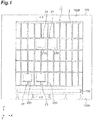
FIG. 1] FIG. 1 is a front view showing a purge stocker including a purge apparatus according to an embodiment. - [
FIG. 2] FIG. 2 is a cross-sectional view of the purge stocker inFIG. 1 as viewed from the line II-II. - [
FIG. 3] FIG. 3(A) is a cross sectional view showing a configuration of a storage container to be purged by the purge apparatus inFIG. 1 .FIG. 3(B) is a perspective view showing a configuration of a storage container to be purged by the purge apparatus inFIG. 1 . - [
FIG. 4] FIG. 4 is a schematic configuration diagram showing a configuration of the purge apparatus inFIG. 1 . - [
FIG. 5] FIG. 5 is a timing chart showing mode switching in a flow rate control unit inFIG. 4 . - [
FIG. 6] FIG. 6 is a graph showing the relation between a supply flow rate and an exhaust flow rate in a state in which a discharge pipe is connected to a discharge port of the storage container. - [
FIG. 7] FIG. 7(A) and FIG. 7(B) are timing charts showing mode switching in the flow rate control unit according to modifications. - An embodiment will be described below with reference to the drawings. In a description of the drawings, the same elements are denoted with the same reference signs, and an overlapping description will be omitted. The scale in the drawings is not always the same.
- A
purge apparatus 30 according to an embodiment will be described. Thepurge apparatus 30 is an apparatus for purging the inside of astorage container 50, such as a front opening unified pod (FOUP), in which a product, such as a semiconductor wafer or a glass substrate, is stored, with a purge gas. Examples of the purge gas as used herein include inert gases and purified dry air. Thepurge apparatus 30 is disposed, for example, in apurge stocker 1 for keeping astorage container 50 in which a product is stored. As shown inFIG. 1 andFIG. 2 , thepurge stocker 1 is provided in, for example, aclean room 100. - The
purge stocker 1 provided in such aclean room 100 includes apartition 3, fan filter units (FFUs) 5,racks 7, acrane 9, anexhaust port 15A, an overhead hoist transfer (OHT)port 21, and amanual port 23. - The
partition 3 is a part that partitions (defines) a region above afloor 100A, and astorage area 1A is formed inside thepartition 3. A plurality ofFFUs 5 are provided along a predetermined direction on the ceiling of a space separated by thepartition 3, that is, above thestorage area 1A. TheFFUs 5 suck the purified air from the outside of thestorage area 1A to the inside of thestorage area 1A to blow the purified air downward of thestorage area 1 A. Theexhaust port 15A is a part provided near the bottom of thestorage area 1A to discharge gas including purge gas from the inside of thestorage area 1A to the outside of thestorage area 1A. The gas including purge gas is discharged from thestorage area 1A by theexhaust fan 15. - The
racks 7 are parts for keepingstorage containers 50 and are provided in multiple rows (here, two rows) in the inside of thestorage area 1A. Eachrack 7 extends in a predetermined direction X, and the two rows ofracks rack 7 has a plurality ofstorage shelves 7A on whichstorage containers 50 are placed and kept, along the predetermined direction X and the vertical direction Z. - The
crane 9 is a part for loading and unloadingstorage containers 50 into/from thestorage shelves 7A and is disposed in a region sandwiched between theracks crane 9 can run on a transport rail (not shown) disposed on the floor along the direction X in which theracks 7 extend, to move along the direction X in which theracks 7 extend. Thecrane 9 has astage 9A that can be lifted and lowered along aguide rail 9B so thatstorage containers 50 can be loaded into and unloaded from a plurality ofstorage shelves 7A provided in the vertical direction. - A
storage container 50 is loaded into and unloaded from thepurge stocker 1 through theOHT port 21 and themanual port 23. TheOHT port 21 is a part for delivering astorage container 50 between thepurge stocker 1 and a ceiling vehicle (OHT) 27 running on atransport rail 25 laid on theceiling 100B and has aconveyor 21A for transferring astorage container 50. Themanual port 23 is a part for delivering astorage container 50 between the operator and thepurge stocker 1 and has aconveyor 23A for transferring astorage container 50. - The
storage shelf 7A of therack 7 is provided with apurge apparatus 30 for purging the inside of thestorage container 50 placed thereon with a purge gas (for example, nitrogen gas). Thepurge apparatus 30 is an apparatus for supplying and discharging a purge gas into thestorage container 50 placed on thestorage shelf 7A. - The
storage container 50 will now be described. As shown inFIG. 3(A) and FIG. 3(B) , thestorage container 50 includes abody 51 and acover 53 to form a casing. Thestorage container 50 has a sealedspace 54 formed with thebody 51 and thecover 53. The sealedspace 54 accommodates a plurality of semiconductor wafers (not shown). - The lower surface of the bottom 52 that is the bottom surface of the
body 51 hasdischarge ports 56 near the right and left ends of the front end, andsupply ports 55 at the right and left ends of the rear end, where the side on which thecover 53 is disposed is the front. Thesupply ports 55 each include aconnection portion 52A and acommunication portion 52C. Thedischarge ports 56 each include aconnection portion 52B and acommunication portion 52D. In this example, theconnection portion 52A is configured to be connectable to thesupply pipe 31 of thepurge apparatus 30 described in details later. Theconnection portion 52B is configured to be connectable to thedischarge pipe 33 of thepurge apparatus 30. Theconnection portions communication portions supply pipe 31 anddischarge pipe 33. Thecommunication portions space 54 with the outside of thestorage container 50. - The
cover 53 is disposed at one face that is a side surface of thebody 51. Thecover 53 is provided with, for example, alatch mechanism 58. Thelatch mechanism 58 has alatch 58A and acam 58B. Thelatch 58A is configured such that an end of thelatch 58A on the side opposite to thecam 58B is put in and out by inserting a key (not shown) into aninsertion hole 58C provided at thecam 58B and turning the key. This end of thelatch 58A is then fitted into afitting groove 51A provided in thebody 51 on the surface facing thelatch 58A, whereby thecover 53 is fixed to thebody 51. - The
purge apparatus 30 will now be described, which purges the inside of thestorage container 50 as described above with a purge gas (for example, nitrogen gas).FIG. 4 is a schematic configuration diagram showing a configuration of thepurge apparatus 30. As shown inFIG. 4 , thepurge apparatus 30 includes asupply pipe 31, a mass flow controller (MFC) 35, apurge gas source 37, adischarge pipe 33, a flowmeter (meter) 39, and acontroller 40. - The front end of the
supply pipe 31 has a nozzle configured to connect to thesupply port 55 of the storage container to supply a purge gas to thestorage container 50. In the present embodiment, thesupply pipe 31 is brought into intimate contact with theconnection portion 52A to be connected to thecommunication portion 52C. TheMFC 35 is equipment that measures the mass flow rate of the purge gas flowing through thesupply pipe 31 and performs flow rate control. Thepurge gas source 37 is a tank for storing a purge gas. - The front end of the
discharge pipe 33 has a nozzle configured to connect to thedischarge port 56 of thestorage container 50 to suck the purge gas in the inside 54 of thestorage container 50 and discharge the purge gas in the inside 54 of thestorage container 50. In the present embodiment, thedischarge pipe 33 is brought into intimate contact with theconnection portion 52B to be connected to thecommunication portion 52D. Theflowmeter 39 is equipment that measures the flow rate of the purge gas flowing through thedischarge pipe 33. - The
controller 40 is a part that controls a variety of purging in thepurge apparatus 30 and is, for example, an electronic control unit including a central processing unit (CPU), a read only memory (ROM), and a random access memory (RAM). As shown inFIG. 4 , thecontroller 40 has a flowrate control unit 41 and a determination unit 43 serving as conceptual units that execute a variety of control processes in thepurge apparatus 30. The functions executed by such conceptual units are executed under the control of the CPU or the like. - The flow
rate control unit 41 is a unit that switches between a first mode in which purging is carried out by supplying purge gas to thestorage container 50 at a first flow rate and a second mode in which purging is carried out by supplying purge gas to thestorage container 50 at a second flow rate. Here, the "first flow rate" refers to a flow rate up to a predetermined flow rate, in thestorage container 50 in which purge gas leaks from a portion other than the discharge port of the storage container 50 (for example, as shown inFIG. 3(A) and FIG. 3(B) , the portion between thebody 51 and the cover 53) when the flow rate of the purge gas supplied to thestorage container 50 is greater than the predetermined flow rate. The "second flow rate" refers to the flow rate greater than the first flow rate. - The determination unit 43 is a unit that determines whether purging is satisfactory, based on the exhaust flow rate measured by the
flowmeter 39. Specifically, the determination unit 43 determines whether purging is satisfactory, based on a supply flow rate Fs by theMFC 35 when controlled with the first flow rate (the first mode) by the flowrate control unit 41, and an exhaust flow rate Fe measured by theflowmeter 39 disposed at thedischarge pipe 33. For example, when the exhaust flow rate Fe is smaller than the supply flow rate Fs by a predetermined amount or more, it can be determined that purging is not being performed satisfactorily. - The determination unit 43 may determine whether purging is satisfactory, considering the flow rate transfer ratios in the not-shown nozzle for injecting purge gas from the front end of the
supply pipe 31 to thestorage container 50 and the not-shown nozzle for injecting purge gas from thestorage container 50 to thedischarge pipe 33. For example, when the flow rate transfer ratio of the nozzle for injecting purge gas to thestorage container 50 in thesupply pipe 31 is defined as A, and the flow rate transfer ratio of the nozzle for injecting purge gas to thedischarge pipe 33 in thestorage container 50 is defined as B, if the exhaust flow rate Fe is smaller than a value obtained by multiplying the supply flow rate Fs by A and B (Fs x A x B), by a predetermined amount or more, it may be determined that purging is not being performed satisfactorily. - The flow rate transfer ratios A and B can be set as appropriate according to the characteristics of the nozzles. If the nozzles are made of metal, a value of 0.70 to 0.95 may be set as the flow rate transfer ratios A and B. If the nozzles are elastic, a value of 0.90 to 1.00 may be set as the flow rate transfer ratios A and B.
- The operation of purging in the foregoing
purge apparatus 30 will now be described. When placement of thestorage container 50 on thepurge apparatus 30 is detected (or the user inputs a purging instruction), the flowrate control unit 41 starts supply of a purge gas to the storage container 50 (purging). As shown inFIG. 5 , the flowrate control unit 41 starts a mode of supplying purge gas at a flow rate f2 that is the second flow rate (the second mode) and continues the second mode until time t1. - The flow
rate control unit 41 thereafter switches to a mode of supplying purge gas at a flow rate f1 that is the first flow rate (the first mode) in order to determine whether the purging is satisfactory, and continues the first mode until time t2. The determination unit 43 determines whether the purging is satisfactory by the method as illustrated above at this time (the first mode). The flowrate control unit 41 thereafter switches again to the mode of supplying purge gas at the flow rate f2 that is the second flow rate (the second mode), and continues the mode for a predetermined time or until thestorage container 50 is moved from thestorage shelf 7A. - The result of the determination by the determination unit 43 as to whether the purging is satisfactory may be indicated to the operator, for example, by display appearing on a not-shown display (not shown) of the
purge apparatus 30, by producing warning sound, or by transmitting information of the result to another terminal. - In the
purge apparatus 30 configured as described above, theflowmeter 39 for measuring the flow rate of the purge gas flowing through thedischarge pipe 33 is provided not in the measuring unit placed on thepurge apparatus 30 but in thepurge apparatus 30. Thus, the exhaust flow rate can be measured when purge gas is supplied to thestorage container 50 in a state in which thestorage container 50 to be purged is actually placed on thepurge apparatus 30, and whether purging is satisfactory can be determined based on the measured exhaust flow rate. Accordingly, whether satisfactory purging is being performed can be determined during a process of actually supplying purge gas to thestorage container 50. - The inventors of the subject application have conducted elaborate studies to find that the exhaust efficiency is greatly affected by the hermeticity of the
storage container 50. That is, as shown inFIG 6 , when the flow rate of purge gas supplied to thestorage container 50 is greater than a predetermined flow rate F1 (when the internal pressure of thestorage container 50 is greater than a predetermined pressure P1), the purge gas leaks from between thecover 53 and thebody 51 of thestorage container 50 and the flow rate of exhaust discharged from thedischarge pipe 33 tends to be saturated. In other words, it has been found that the exhaust flow rate substantially proportional to the supply flow rate is obtained up to the predetermined flow rate F1 (0 to F1) at which purge gas leaks from between thecover 53 and thebody 51 of thestorage container 50. - The
purge apparatus 30 configured as described above is switchable between the first mode in which purging is carried out by supplying purge gas to thestorage container 50 at a first flow rate f1 and the second mode in which purging is carried out by supplying purge gas to thestorage container 50 at a second flow rate f2, where the first flow rate f1 is a supply flow rate up to a predetermined flow rate F1, in thestorage container 50 in which purge gas leaks from between thecover 53 and thebody 51 of thestorage container 50 when the flow rate of the purge gas supplied to thestorage container 50 is greater than the predetermined flow rate F1, as shown inFIG. 6 , and the second flow rate f2 is a flow rate greater than the first flow rate. Thepurge apparatus 30 then measures the exhaust flow rate in the first mode and determines whether purging is satisfactory based on the exhaust flow rate measured in the first mode. - This
purge apparatus 30 determines whether purging is satisfactory, based on the supply flow rate that is the first flow rate f1 at which the exhaust flow rate is substantially proportional to the supply flow rate, and the exhaust flow rate obtained when purging is performed at the first flow rate f1. Thus, whether purging is satisfactory can be determined based on the supply flow rate and the exhaust flow rate substantially proportional to each other, thereby enabling an accurate determination. - The
purge apparatus 30 configured as described above starts purging in the second mode, thereafter switches to the first mode, measures the exhaust flow rate in the first mode, and determines whether purging is satisfactory, based on the exhaust flow rate measured in the first mode. Thus, purge gas is initially supplied to thestorage container 50 at a relatively large flow rate, so that the inside of thestorage container 50 can be cleaned early. This can reduce the possibility that the product is contaminated. - Although an embodiment of the present invention has been described above, the present invention is not limited to the foregoing embodiment and susceptible to various modifications without departing form the scope of the invention.
- In the
purge stocker 1 in the foregoing embodiment, the first mode and the second mode are switched at the timings illustrated inFIG. 5 . However, the present invention is not limited to this embodiment. For example, as shown inFIG. 7(A) , thepurge apparatus 30 may start purging in the first mode, determine whether purging is satisfactory based on the exhaust flow rate measured in the first mode, and then switch to the second mode to continue the purging. In this case, whether purging is satisfactory can be determined at an early stage in the purging, so that if a problem arises, measures can be taken early. - As shown in
FIG. 7(B) , thepurge apparatus 30 may start purging in the second mode, switch to the first mode at the last stage in which the purging is terminated, determine whether the purging is satisfactory based on the exhaust flow rate measured in the first mode, and terminate the purging as it is. In this case, purge gas is initially supplied to thestorage container 50 at a relatively large flow rate, so that the inside of thestorage container 50 can be cleaned early. This control is effective when whether purging has been performed satisfactorily is confirmed at any timing. - In the foregoing embodiment, the
purge apparatus 30 disposed in thepurge stocker 1 has been illustrated. However, the present invention is not limited to this embodiment. The present invention is not limited to a purge apparatus disposed in a space defined by thepartition 3 or the like, and the purge apparatus in the foregoing embodiment and modifications is applicable to, for example, a relay point between ceiling vehicles, a delivery point (load port) from a conveyor to a ceiling vehicle, and a ceiling buffer. - 1 ... purge stocker, 1A ... storage area, 3 ... partition, 7 ... rack, 7A ... storage shelf, 21 ... OHT port, 23 ... manual port, 30 ... purge apparatus, 31 ... supply pipe, 33 ... discharge pipe, 37 ... purge gas source, 39 ... flowmeter (meter), 40 ... controller, 41 ... flow rate control unit, 43 ... determination unit, 50 ... storage container, 51 ... body, 52 ... bottom, 53 ... cover, 54 ... sealed space, 55 ... supply port, 56 ... discharge port, 100 ... clean room.
Claims (5)
- A purge apparatus for purging an inside of a storage container in which a product is stored, with a purge gas, the purge apparatus comprising:a discharge pipe configured to connect to a discharge port of the storage container to discharge the purge gas inside the storage container;a meter configured to measure an exhaust flow rate that is a flow rate of the purge gas flowing through the discharge pipe when the purging is carried out; anda determination unit configured to determine whether the purging is satisfactory, based on the exhaust flow rate measured by the meter.
- The purge apparatus according to claim 1, further comprising a flow rate control unit configured to switch between a first mode in which the purging is carried out by supplying the purge gas to the storage container at a first flow rate and a second mode in which the purging is carried out by supplying the purge gas to the storage container at a second flow rate, the first flow rate being a flow rate up to a predetermined flow rate, in the storage container in which the purge gas leaks from a portion other than the discharge port of the storage container when the flow rate of the purge gas supplied to the storage container is greater than the predetermined flow rate, the second flow rate being a flow rate greater than the first flow rate, wherein
the meter measures the exhaust flow rate in the first mode, and
the determination unit determines whether the purging is satisfactory, based on the exhaust flow rate measured in the first mode. - The purge apparatus according to claim 2, wherein the flow rate control unit starts the purging in the second mode, switches to the first mode to perform the purging to determine whether the purging is satisfactory, and performs again the purging in the second mode.
- A purge method of purging an inside of a storage container in which a product is stored, with a purge gas, the purge method comprising:connecting a discharge pipe to a discharge port of the storage container, the discharge pipe being capable of discharging the purge gas inside the storage container;measuring an exhaust flow rate that is a flow rate of the purge gas flowing through the discharge pipe when the purging is carried out; anddetermining whether the purging is satisfactory, based on the measured exhaust flow rate.
- A purge method according to claim 4, wherein
an exhaust flow rate that is a flow rate of the purge gas flowing through the discharge pipe when the purging is carried out by supplying the purge gas to the storage container at a first flow rate is measured, and whether the purging is satisfactory is determined based on the measured exhaust flow rate, the first flow rate being a flow rate up to a predetermined flow rate, in the storage container in which the purge gas leaks from a portion other than the discharge port of the storage container when the flow rate of the purge gas supplied to the storage container is greater than the predetermined flow rate, a second flow rate being a flow rate greater than the first flow rate.
Applications Claiming Priority (2)
| Application Number | Priority Date | Filing Date | Title |
|---|---|---|---|
| JP2014022508 | 2014-02-07 | ||
| PCT/JP2014/083436 WO2015118782A1 (en) | 2014-02-07 | 2014-12-17 | Purge device and purge method |
Publications (3)
| Publication Number | Publication Date |
|---|---|
| EP3104401A1 true EP3104401A1 (en) | 2016-12-14 |
| EP3104401A4 EP3104401A4 (en) | 2017-09-20 |
| EP3104401B1 EP3104401B1 (en) | 2021-02-03 |
Family
ID=53777598
Family Applications (1)
| Application Number | Title | Priority Date | Filing Date |
|---|---|---|---|
| EP14881475.9A Active EP3104401B1 (en) | 2014-02-07 | 2014-12-17 | Purge device and purge method |
Country Status (9)
| Country | Link |
|---|---|
| US (1) | US10438829B2 (en) |
| EP (1) | EP3104401B1 (en) |
| JP (1) | JP6132036B2 (en) |
| KR (1) | KR101822009B1 (en) |
| CN (1) | CN105940487B (en) |
| IL (1) | IL246992B (en) |
| SG (1) | SG11201606283WA (en) |
| TW (1) | TWI649797B (en) |
| WO (1) | WO2015118782A1 (en) |
Cited By (1)
| Publication number | Priority date | Publication date | Assignee | Title |
|---|---|---|---|---|
| EP4216260A4 (en) * | 2020-10-05 | 2024-10-30 | Murata Machinery, Ltd. | FLOW MEASURING DEVICE |
Families Citing this family (26)
| Publication number | Priority date | Publication date | Assignee | Title |
|---|---|---|---|---|
| JP6217855B2 (en) * | 2014-06-16 | 2017-10-25 | 村田機械株式会社 | Purge apparatus, purge system, purge method, and control method in purge system |
| US10586721B2 (en) * | 2015-08-25 | 2020-03-10 | Murata Machinery, Ltd. | Purge device, purge stocker, and purge method |
| JP6414525B2 (en) * | 2015-09-02 | 2018-10-31 | 株式会社ダイフク | Storage facilities |
| JP2018536984A (en) * | 2015-10-05 | 2018-12-13 | ブルックス シーシーエス ゲーエムベーハーBrooks CCS GmbH | Humidity control in semiconductor systems |
| JP6679907B2 (en) * | 2015-12-11 | 2020-04-15 | Tdk株式会社 | Load port device and method for introducing cleaning gas into container in load port device |
| DE102016205597B4 (en) * | 2016-04-05 | 2022-06-23 | Fabmatics Gmbh | Purge measurement system for FOUPs |
| FR3058562B1 (en) * | 2016-11-07 | 2019-05-10 | Pfeiffer Vacuum | DEVICE AND METHOD FOR CONTROLLING THE SEALING OF A TRANSPORT ENCLOSURE FOR CONVEYING AND ATMOSPHERIC STORAGE OF SEMICONDUCTOR SUBSTRATES |
| EP3584827B1 (en) * | 2017-02-20 | 2022-02-16 | Murata Machinery, Ltd. | Purge stocker |
| US10388547B2 (en) * | 2017-06-23 | 2019-08-20 | Applied Materials, Inc. | Side storage pods, equipment front end modules, and methods for processing substrates |
| JP6917839B2 (en) * | 2017-09-13 | 2021-08-11 | 株式会社Screenホールディングス | Cleaning equipment, cleaning methods and liquid supply equipment |
| JP7184453B2 (en) * | 2018-05-17 | 2022-12-06 | 株式会社ディスコ | Conveyor system |
| CN110838461B (en) * | 2018-08-16 | 2023-09-08 | 细美事有限公司 | Purifying device and purifying method |
| KR102190920B1 (en) * | 2018-08-16 | 2020-12-16 | 세메스 주식회사 | Purge apparatus and purge method |
| WO2020065968A1 (en) * | 2018-09-28 | 2020-04-02 | ミライアル株式会社 | Substrate accommodation container |
| KR102303262B1 (en) * | 2019-01-15 | 2021-09-16 | 세메스 주식회사 | Purge apparatus and purge method |
| EP4057325A4 (en) * | 2019-11-05 | 2023-11-22 | Murata Machinery, Ltd. | Transport vehicle system |
| JP7422577B2 (en) * | 2020-03-23 | 2024-01-26 | 平田機工株式会社 | Load port and control method |
| CN111672849B (en) * | 2020-05-27 | 2021-08-17 | 四川蓝鼎新材料有限公司 | Gypsum powder dust automatic processing device |
| CN113941211A (en) * | 2020-07-17 | 2022-01-18 | 中国科学院微电子研究所 | Flue gas treatment device, semiconductor manufacturing equipment and flue gas treatment method |
| KR102643103B1 (en) * | 2021-06-11 | 2024-03-06 | 세메스 주식회사 | Apparatus for treating substrate |
| KR102353302B1 (en) | 2021-07-13 | 2022-01-21 | 주식회사 올소비트 | Methods and devices for manufacturing dental medical supplies by 3D printing using purge gas charging with positive pressure |
| JP7574779B2 (en) * | 2021-10-26 | 2024-10-29 | 株式会社ダイフク | Purging device and container storage facility equipped with purging device |
| US20230131451A1 (en) * | 2021-10-27 | 2023-04-27 | Entegris, Inc. | Method and device to regulate purge into a container |
| TWI823487B (en) * | 2022-02-17 | 2023-11-21 | 盟立自動化股份有限公司 | Rail switching mechanism and transfer system of overhead hoist transfer |
| TWI819953B (en) * | 2023-01-13 | 2023-10-21 | 科嶠工業股份有限公司 | Cleanliness detection method and device thereof for a front opening unified pod |
| JP2025102459A (en) * | 2023-12-26 | 2025-07-08 | 東京エレクトロン株式会社 | DETECTION METHOD, SUBSTRATE PROCESSING SYSTEM, AND CONTROL PROGRAM |
Family Cites Families (10)
| Publication number | Priority date | Publication date | Assignee | Title |
|---|---|---|---|---|
| US5879458A (en) | 1996-09-13 | 1999-03-09 | Semifab Incorporated | Molecular contamination control system |
| JP4308975B2 (en) * | 1999-05-27 | 2009-08-05 | 株式会社日立国際電気 | Substrate processing apparatus, substrate processing method, and semiconductor element forming method |
| KR20120099802A (en) * | 2004-02-05 | 2012-09-11 | 엔테그리스, 아이엔씨. | Purging of a wafer conveyance container |
| JP4670808B2 (en) | 2006-12-22 | 2011-04-13 | ムラテックオートメーション株式会社 | Container transport system and measuring container |
| IL180875A0 (en) * | 2007-01-22 | 2007-07-04 | Ricor Ltd | Gas purge method and apparatus |
| JP5155848B2 (en) * | 2008-12-18 | 2013-03-06 | 日本ケンブリッジフィルター株式会社 | N2 purge device for FOUP |
| JP5236518B2 (en) * | 2009-02-03 | 2013-07-17 | 株式会社ダン・タクマ | Storage system and storage method |
| JP5501916B2 (en) * | 2010-09-27 | 2014-05-28 | 東レエンジニアリング株式会社 | Substrate processing system |
| TWM419220U (en) * | 2011-08-16 | 2011-12-21 | Yu Tech Integrated System Corp | Wafer cleaning apparatus for a front opening unified pod |
| JP6087161B2 (en) * | 2012-02-03 | 2017-03-01 | 東京エレクトロン株式会社 | Method for purging substrate container |
-
2014
- 2014-12-17 US US15/116,527 patent/US10438829B2/en active Active
- 2014-12-17 CN CN201480074707.5A patent/CN105940487B/en active Active
- 2014-12-17 KR KR1020167020559A patent/KR101822009B1/en active Active
- 2014-12-17 SG SG11201606283WA patent/SG11201606283WA/en unknown
- 2014-12-17 JP JP2015561180A patent/JP6132036B2/en active Active
- 2014-12-17 WO PCT/JP2014/083436 patent/WO2015118782A1/en not_active Ceased
- 2014-12-17 EP EP14881475.9A patent/EP3104401B1/en active Active
-
2015
- 2015-01-21 TW TW104101967A patent/TWI649797B/en active
-
2016
- 2016-07-28 IL IL246992A patent/IL246992B/en active IP Right Grant
Cited By (1)
| Publication number | Priority date | Publication date | Assignee | Title |
|---|---|---|---|---|
| EP4216260A4 (en) * | 2020-10-05 | 2024-10-30 | Murata Machinery, Ltd. | FLOW MEASURING DEVICE |
Also Published As
| Publication number | Publication date |
|---|---|
| WO2015118782A1 (en) | 2015-08-13 |
| US10438829B2 (en) | 2019-10-08 |
| JPWO2015118782A1 (en) | 2017-03-23 |
| CN105940487B (en) | 2018-12-04 |
| IL246992B (en) | 2019-02-28 |
| TW201537629A (en) | 2015-10-01 |
| SG11201606283WA (en) | 2016-09-29 |
| EP3104401A4 (en) | 2017-09-20 |
| EP3104401B1 (en) | 2021-02-03 |
| US20160351427A1 (en) | 2016-12-01 |
| CN105940487A (en) | 2016-09-14 |
| JP6132036B2 (en) | 2017-05-24 |
| KR20160102560A (en) | 2016-08-30 |
| TWI649797B (en) | 2019-02-01 |
| KR101822009B1 (en) | 2018-03-08 |
Similar Documents
| Publication | Publication Date | Title |
|---|---|---|
| EP3104401B1 (en) | Purge device and purge method | |
| JP6052469B2 (en) | Purge apparatus and purge method | |
| KR102232129B1 (en) | Substrate processing apparatus and substrate transfer method | |
| CN108140598B (en) | Blowing-out device, blowing-out stocker and blowing-out method | |
| US9412631B2 (en) | Ceiling storage device capable of wafer purging | |
| KR101674454B1 (en) | Side track buffer for foup purging | |
| US11367642B2 (en) | Substrate processing apparatus and purging method | |
| EP3157048B1 (en) | Purge device, purge system, purge method, and control method in purge system | |
| JP5709011B2 (en) | Goods storage facility | |
| TWI868516B (en) | Conveying system, container opening and closing device | |
| CN113169103A (en) | Wafer storage device | |
| TWI665142B (en) | Storage device and storage method | |
| CN104603032A (en) | Stocker provided with purging functionality, stocker unit, and method for supplying cleaning gas | |
| CN108398168A (en) | Flow measuring systems | |
| TW201812962A (en) | Container storage equipment | |
| JP2017017291A (en) | Hoop load port device | |
| US8577502B2 (en) | Liquid processing apparatus, liquid processing method, computer program, and storage medium | |
| KR101017189B1 (en) | Wafer Thin Film Thickness Measuring Equipment | |
| JP2023064543A (en) | Purge device and container housing facility with purge device | |
| KR20170009406A (en) | Flow meters for foup purging module |
Legal Events
| Date | Code | Title | Description |
|---|---|---|---|
| PUAI | Public reference made under article 153(3) epc to a published international application that has entered the european phase |
Free format text: ORIGINAL CODE: 0009012 |
|
| STAA | Information on the status of an ep patent application or granted ep patent |
Free format text: STATUS: REQUEST FOR EXAMINATION WAS MADE |
|
| 17P | Request for examination filed |
Effective date: 20160801 |
|
| AK | Designated contracting states |
Kind code of ref document: A1 Designated state(s): AL AT BE BG CH CY CZ DE DK EE ES FI FR GB GR HR HU IE IS IT LI LT LU LV MC MK MT NL NO PL PT RO RS SE SI SK SM TR |
|
| AX | Request for extension of the european patent |
Extension state: BA ME |
|
| DAX | Request for extension of the european patent (deleted) | ||
| A4 | Supplementary search report drawn up and despatched |
Effective date: 20170822 |
|
| RIC1 | Information provided on ipc code assigned before grant |
Ipc: B08B 5/04 20060101ALI20170816BHEP Ipc: H01L 21/67 20060101ALI20170816BHEP Ipc: H01L 21/677 20060101ALI20170816BHEP Ipc: B65G 1/00 20060101ALI20170816BHEP Ipc: B08B 9/08 20060101ALI20170816BHEP Ipc: B65D 85/86 20060101ALI20170816BHEP Ipc: H01L 21/673 20060101AFI20170816BHEP |
|
| GRAP | Despatch of communication of intention to grant a patent |
Free format text: ORIGINAL CODE: EPIDOSNIGR1 |
|
| STAA | Information on the status of an ep patent application or granted ep patent |
Free format text: STATUS: GRANT OF PATENT IS INTENDED |
|
| INTG | Intention to grant announced |
Effective date: 20200710 |
|
| GRAS | Grant fee paid |
Free format text: ORIGINAL CODE: EPIDOSNIGR3 |
|
| GRAL | Information related to payment of fee for publishing/printing deleted |
Free format text: ORIGINAL CODE: EPIDOSDIGR3 |
|
| GRAS | Grant fee paid |
Free format text: ORIGINAL CODE: EPIDOSNIGR3 |
|
| GRAA | (expected) grant |
Free format text: ORIGINAL CODE: 0009210 |
|
| STAA | Information on the status of an ep patent application or granted ep patent |
Free format text: STATUS: THE PATENT HAS BEEN GRANTED |
|
| AK | Designated contracting states |
Kind code of ref document: B1 Designated state(s): AL AT BE BG CH CY CZ DE DK EE ES FI FR GB GR HR HU IE IS IT LI LT LU LV MC MK MT NL NO PL PT RO RS SE SI SK SM TR |
|
| REG | Reference to a national code |
Ref country code: GB Ref legal event code: FG4D |
|
| REG | Reference to a national code |
Ref country code: AT Ref legal event code: REF Ref document number: 1359874 Country of ref document: AT Kind code of ref document: T Effective date: 20210215 Ref country code: CH Ref legal event code: EP |
|
| REG | Reference to a national code |
Ref country code: DE Ref legal event code: R096 Ref document number: 602014074743 Country of ref document: DE |
|
| REG | Reference to a national code |
Ref country code: IE Ref legal event code: FG4D |
|
| REG | Reference to a national code |
Ref country code: NL Ref legal event code: MP Effective date: 20210203 |
|
| REG | Reference to a national code |
Ref country code: LT Ref legal event code: MG9D |
|
| REG | Reference to a national code |
Ref country code: AT Ref legal event code: MK05 Ref document number: 1359874 Country of ref document: AT Kind code of ref document: T Effective date: 20210203 |
|
| PG25 | Lapsed in a contracting state [announced via postgrant information from national office to epo] |
Ref country code: LT Free format text: LAPSE BECAUSE OF FAILURE TO SUBMIT A TRANSLATION OF THE DESCRIPTION OR TO PAY THE FEE WITHIN THE PRESCRIBED TIME-LIMIT Effective date: 20210203 Ref country code: PT Free format text: LAPSE BECAUSE OF FAILURE TO SUBMIT A TRANSLATION OF THE DESCRIPTION OR TO PAY THE FEE WITHIN THE PRESCRIBED TIME-LIMIT Effective date: 20210604 Ref country code: FI Free format text: LAPSE BECAUSE OF FAILURE TO SUBMIT A TRANSLATION OF THE DESCRIPTION OR TO PAY THE FEE WITHIN THE PRESCRIBED TIME-LIMIT Effective date: 20210203 Ref country code: HR Free format text: LAPSE BECAUSE OF FAILURE TO SUBMIT A TRANSLATION OF THE DESCRIPTION OR TO PAY THE FEE WITHIN THE PRESCRIBED TIME-LIMIT Effective date: 20210203 Ref country code: GR Free format text: LAPSE BECAUSE OF FAILURE TO SUBMIT A TRANSLATION OF THE DESCRIPTION OR TO PAY THE FEE WITHIN THE PRESCRIBED TIME-LIMIT Effective date: 20210504 Ref country code: BG Free format text: LAPSE BECAUSE OF FAILURE TO SUBMIT A TRANSLATION OF THE DESCRIPTION OR TO PAY THE FEE WITHIN THE PRESCRIBED TIME-LIMIT Effective date: 20210503 Ref country code: NO Free format text: LAPSE BECAUSE OF FAILURE TO SUBMIT A TRANSLATION OF THE DESCRIPTION OR TO PAY THE FEE WITHIN THE PRESCRIBED TIME-LIMIT Effective date: 20210503 |
|
| PG25 | Lapsed in a contracting state [announced via postgrant information from national office to epo] |
Ref country code: PL Free format text: LAPSE BECAUSE OF FAILURE TO SUBMIT A TRANSLATION OF THE DESCRIPTION OR TO PAY THE FEE WITHIN THE PRESCRIBED TIME-LIMIT Effective date: 20210203 Ref country code: NL Free format text: LAPSE BECAUSE OF FAILURE TO SUBMIT A TRANSLATION OF THE DESCRIPTION OR TO PAY THE FEE WITHIN THE PRESCRIBED TIME-LIMIT Effective date: 20210203 Ref country code: LV Free format text: LAPSE BECAUSE OF FAILURE TO SUBMIT A TRANSLATION OF THE DESCRIPTION OR TO PAY THE FEE WITHIN THE PRESCRIBED TIME-LIMIT Effective date: 20210203 Ref country code: RS Free format text: LAPSE BECAUSE OF FAILURE TO SUBMIT A TRANSLATION OF THE DESCRIPTION OR TO PAY THE FEE WITHIN THE PRESCRIBED TIME-LIMIT Effective date: 20210203 Ref country code: AT Free format text: LAPSE BECAUSE OF FAILURE TO SUBMIT A TRANSLATION OF THE DESCRIPTION OR TO PAY THE FEE WITHIN THE PRESCRIBED TIME-LIMIT Effective date: 20210203 Ref country code: SE Free format text: LAPSE BECAUSE OF FAILURE TO SUBMIT A TRANSLATION OF THE DESCRIPTION OR TO PAY THE FEE WITHIN THE PRESCRIBED TIME-LIMIT Effective date: 20210203 |
|
| PG25 | Lapsed in a contracting state [announced via postgrant information from national office to epo] |
Ref country code: IS Free format text: LAPSE BECAUSE OF FAILURE TO SUBMIT A TRANSLATION OF THE DESCRIPTION OR TO PAY THE FEE WITHIN THE PRESCRIBED TIME-LIMIT Effective date: 20210603 |
|
| PG25 | Lapsed in a contracting state [announced via postgrant information from national office to epo] |
Ref country code: SM Free format text: LAPSE BECAUSE OF FAILURE TO SUBMIT A TRANSLATION OF THE DESCRIPTION OR TO PAY THE FEE WITHIN THE PRESCRIBED TIME-LIMIT Effective date: 20210203 Ref country code: CZ Free format text: LAPSE BECAUSE OF FAILURE TO SUBMIT A TRANSLATION OF THE DESCRIPTION OR TO PAY THE FEE WITHIN THE PRESCRIBED TIME-LIMIT Effective date: 20210203 Ref country code: EE Free format text: LAPSE BECAUSE OF FAILURE TO SUBMIT A TRANSLATION OF THE DESCRIPTION OR TO PAY THE FEE WITHIN THE PRESCRIBED TIME-LIMIT Effective date: 20210203 |
|
| REG | Reference to a national code |
Ref country code: DE Ref legal event code: R097 Ref document number: 602014074743 Country of ref document: DE |
|
| PG25 | Lapsed in a contracting state [announced via postgrant information from national office to epo] |
Ref country code: SK Free format text: LAPSE BECAUSE OF FAILURE TO SUBMIT A TRANSLATION OF THE DESCRIPTION OR TO PAY THE FEE WITHIN THE PRESCRIBED TIME-LIMIT Effective date: 20210203 Ref country code: RO Free format text: LAPSE BECAUSE OF FAILURE TO SUBMIT A TRANSLATION OF THE DESCRIPTION OR TO PAY THE FEE WITHIN THE PRESCRIBED TIME-LIMIT Effective date: 20210203 Ref country code: DK Free format text: LAPSE BECAUSE OF FAILURE TO SUBMIT A TRANSLATION OF THE DESCRIPTION OR TO PAY THE FEE WITHIN THE PRESCRIBED TIME-LIMIT Effective date: 20210203 Ref country code: ES Free format text: LAPSE BECAUSE OF FAILURE TO SUBMIT A TRANSLATION OF THE DESCRIPTION OR TO PAY THE FEE WITHIN THE PRESCRIBED TIME-LIMIT Effective date: 20210203 |
|
| PLBE | No opposition filed within time limit |
Free format text: ORIGINAL CODE: 0009261 |
|
| STAA | Information on the status of an ep patent application or granted ep patent |
Free format text: STATUS: NO OPPOSITION FILED WITHIN TIME LIMIT |
|
| 26N | No opposition filed |
Effective date: 20211104 |
|
| PG25 | Lapsed in a contracting state [announced via postgrant information from national office to epo] |
Ref country code: AL Free format text: LAPSE BECAUSE OF FAILURE TO SUBMIT A TRANSLATION OF THE DESCRIPTION OR TO PAY THE FEE WITHIN THE PRESCRIBED TIME-LIMIT Effective date: 20210203 |
|
| PG25 | Lapsed in a contracting state [announced via postgrant information from national office to epo] |
Ref country code: SI Free format text: LAPSE BECAUSE OF FAILURE TO SUBMIT A TRANSLATION OF THE DESCRIPTION OR TO PAY THE FEE WITHIN THE PRESCRIBED TIME-LIMIT Effective date: 20210203 |
|
| PG25 | Lapsed in a contracting state [announced via postgrant information from national office to epo] |
Ref country code: IT Free format text: LAPSE BECAUSE OF FAILURE TO SUBMIT A TRANSLATION OF THE DESCRIPTION OR TO PAY THE FEE WITHIN THE PRESCRIBED TIME-LIMIT Effective date: 20210203 |
|
| PG25 | Lapsed in a contracting state [announced via postgrant information from national office to epo] |
Ref country code: IS Free format text: LAPSE BECAUSE OF FAILURE TO SUBMIT A TRANSLATION OF THE DESCRIPTION OR TO PAY THE FEE WITHIN THE PRESCRIBED TIME-LIMIT Effective date: 20210603 |
|
| PG25 | Lapsed in a contracting state [announced via postgrant information from national office to epo] |
Ref country code: MC Free format text: LAPSE BECAUSE OF FAILURE TO SUBMIT A TRANSLATION OF THE DESCRIPTION OR TO PAY THE FEE WITHIN THE PRESCRIBED TIME-LIMIT Effective date: 20210203 |
|
| REG | Reference to a national code |
Ref country code: CH Ref legal event code: PL |
|
| GBPC | Gb: european patent ceased through non-payment of renewal fee |
Effective date: 20211217 |
|
| REG | Reference to a national code |
Ref country code: BE Ref legal event code: MM Effective date: 20211231 |
|
| PG25 | Lapsed in a contracting state [announced via postgrant information from national office to epo] |
Ref country code: LU Free format text: LAPSE BECAUSE OF NON-PAYMENT OF DUE FEES Effective date: 20211217 Ref country code: GB Free format text: LAPSE BECAUSE OF NON-PAYMENT OF DUE FEES Effective date: 20211217 |
|
| PG25 | Lapsed in a contracting state [announced via postgrant information from national office to epo] |
Ref country code: FR Free format text: LAPSE BECAUSE OF NON-PAYMENT OF DUE FEES Effective date: 20211231 Ref country code: BE Free format text: LAPSE BECAUSE OF NON-PAYMENT OF DUE FEES Effective date: 20211231 |
|
| PG25 | Lapsed in a contracting state [announced via postgrant information from national office to epo] |
Ref country code: LI Free format text: LAPSE BECAUSE OF NON-PAYMENT OF DUE FEES Effective date: 20211231 Ref country code: CH Free format text: LAPSE BECAUSE OF NON-PAYMENT OF DUE FEES Effective date: 20211231 |
|
| PG25 | Lapsed in a contracting state [announced via postgrant information from national office to epo] |
Ref country code: HU Free format text: LAPSE BECAUSE OF FAILURE TO SUBMIT A TRANSLATION OF THE DESCRIPTION OR TO PAY THE FEE WITHIN THE PRESCRIBED TIME-LIMIT; INVALID AB INITIO Effective date: 20141217 |
|
| PG25 | Lapsed in a contracting state [announced via postgrant information from national office to epo] |
Ref country code: CY Free format text: LAPSE BECAUSE OF FAILURE TO SUBMIT A TRANSLATION OF THE DESCRIPTION OR TO PAY THE FEE WITHIN THE PRESCRIBED TIME-LIMIT Effective date: 20210203 |
|
| PG25 | Lapsed in a contracting state [announced via postgrant information from national office to epo] |
Ref country code: MK Free format text: LAPSE BECAUSE OF FAILURE TO SUBMIT A TRANSLATION OF THE DESCRIPTION OR TO PAY THE FEE WITHIN THE PRESCRIBED TIME-LIMIT Effective date: 20210203 |
|
| PG25 | Lapsed in a contracting state [announced via postgrant information from national office to epo] |
Ref country code: MT Free format text: LAPSE BECAUSE OF FAILURE TO SUBMIT A TRANSLATION OF THE DESCRIPTION OR TO PAY THE FEE WITHIN THE PRESCRIBED TIME-LIMIT Effective date: 20210203 |
|
| REG | Reference to a national code |
Ref country code: DE Ref legal event code: R079 Ref document number: 602014074743 Country of ref document: DE Free format text: PREVIOUS MAIN CLASS: H01L0021673000 Ipc: H10P0072100000 |
|
| PG25 | Lapsed in a contracting state [announced via postgrant information from national office to epo] |
Ref country code: TR Free format text: LAPSE BECAUSE OF FAILURE TO SUBMIT A TRANSLATION OF THE DESCRIPTION OR TO PAY THE FEE WITHIN THE PRESCRIBED TIME-LIMIT Effective date: 20210203 |
|
| PGFP | Annual fee paid to national office [announced via postgrant information from national office to epo] |
Ref country code: DE Payment date: 20251126 Year of fee payment: 12 |
|
| PGFP | Annual fee paid to national office [announced via postgrant information from national office to epo] |
Ref country code: IE Payment date: 20251121 Year of fee payment: 12 |