EP3104368A1 - Carbon-fiber-composite heat-collecting tile and method for producing same - Google Patents
Carbon-fiber-composite heat-collecting tile and method for producing same Download PDFInfo
- Publication number
- EP3104368A1 EP3104368A1 EP15747046.9A EP15747046A EP3104368A1 EP 3104368 A1 EP3104368 A1 EP 3104368A1 EP 15747046 A EP15747046 A EP 15747046A EP 3104368 A1 EP3104368 A1 EP 3104368A1
- Authority
- EP
- European Patent Office
- Prior art keywords
- heat receiving
- carbon fiber
- fiber composite
- receiving block
- composite material
- Prior art date
- Legal status (The legal status is an assumption and is not a legal conclusion. Google has not performed a legal analysis and makes no representation as to the accuracy of the status listed.)
- Granted
Links
Images



Classifications
-
- F—MECHANICAL ENGINEERING; LIGHTING; HEATING; WEAPONS; BLASTING
- F28—HEAT EXCHANGE IN GENERAL
- F28D—HEAT-EXCHANGE APPARATUS, NOT PROVIDED FOR IN ANOTHER SUBCLASS, IN WHICH THE HEAT-EXCHANGE MEDIA DO NOT COME INTO DIRECT CONTACT
- F28D20/00—Heat storage plants or apparatus in general; Regenerative heat-exchange apparatus not covered by groups F28D17/00 or F28D19/00
- F28D20/0056—Heat storage plants or apparatus in general; Regenerative heat-exchange apparatus not covered by groups F28D17/00 or F28D19/00 using solid heat storage material
-
- B—PERFORMING OPERATIONS; TRANSPORTING
- B23—MACHINE TOOLS; METAL-WORKING NOT OTHERWISE PROVIDED FOR
- B23K—SOLDERING OR UNSOLDERING; WELDING; CLADDING OR PLATING BY SOLDERING OR WELDING; CUTTING BY APPLYING HEAT LOCALLY, e.g. FLAME CUTTING; WORKING BY LASER BEAM
- B23K1/00—Soldering, e.g. brazing, or unsoldering
- B23K1/19—Soldering, e.g. brazing, or unsoldering taking account of the properties of the materials to be soldered
-
- F—MECHANICAL ENGINEERING; LIGHTING; HEATING; WEAPONS; BLASTING
- F28—HEAT EXCHANGE IN GENERAL
- F28D—HEAT-EXCHANGE APPARATUS, NOT PROVIDED FOR IN ANOTHER SUBCLASS, IN WHICH THE HEAT-EXCHANGE MEDIA DO NOT COME INTO DIRECT CONTACT
- F28D20/00—Heat storage plants or apparatus in general; Regenerative heat-exchange apparatus not covered by groups F28D17/00 or F28D19/00
-
- G—PHYSICS
- G21—NUCLEAR PHYSICS; NUCLEAR ENGINEERING
- G21B—FUSION REACTORS
- G21B1/00—Thermonuclear fusion reactors
- G21B1/11—Details
- G21B1/13—First wall; Blanket; Divertor
-
- B—PERFORMING OPERATIONS; TRANSPORTING
- B23—MACHINE TOOLS; METAL-WORKING NOT OTHERWISE PROVIDED FOR
- B23K—SOLDERING OR UNSOLDERING; WELDING; CLADDING OR PLATING BY SOLDERING OR WELDING; CUTTING BY APPLYING HEAT LOCALLY, e.g. FLAME CUTTING; WORKING BY LASER BEAM
- B23K2103/00—Materials to be soldered, welded or cut
- B23K2103/08—Non-ferrous metals or alloys
- B23K2103/12—Copper or alloys thereof
-
- F—MECHANICAL ENGINEERING; LIGHTING; HEATING; WEAPONS; BLASTING
- F28—HEAT EXCHANGE IN GENERAL
- F28F—DETAILS OF HEAT-EXCHANGE AND HEAT-TRANSFER APPARATUS, OF GENERAL APPLICATION
- F28F19/00—Preventing the formation of deposits or corrosion, e.g. by using filters or scrapers
- F28F19/02—Preventing the formation of deposits or corrosion, e.g. by using filters or scrapers by using coatings, e.g. vitreous or enamel coatings
-
- F—MECHANICAL ENGINEERING; LIGHTING; HEATING; WEAPONS; BLASTING
- F28—HEAT EXCHANGE IN GENERAL
- F28F—DETAILS OF HEAT-EXCHANGE AND HEAT-TRANSFER APPARATUS, OF GENERAL APPLICATION
- F28F21/00—Constructions of heat-exchange apparatus characterised by the selection of particular materials
- F28F21/02—Constructions of heat-exchange apparatus characterised by the selection of particular materials of carbon, e.g. graphite
-
- F—MECHANICAL ENGINEERING; LIGHTING; HEATING; WEAPONS; BLASTING
- F28—HEAT EXCHANGE IN GENERAL
- F28F—DETAILS OF HEAT-EXCHANGE AND HEAT-TRANSFER APPARATUS, OF GENERAL APPLICATION
- F28F21/00—Constructions of heat-exchange apparatus characterised by the selection of particular materials
- F28F21/08—Constructions of heat-exchange apparatus characterised by the selection of particular materials of metal
-
- F—MECHANICAL ENGINEERING; LIGHTING; HEATING; WEAPONS; BLASTING
- F28—HEAT EXCHANGE IN GENERAL
- F28F—DETAILS OF HEAT-EXCHANGE AND HEAT-TRANSFER APPARATUS, OF GENERAL APPLICATION
- F28F2275/00—Fastening; Joining
- F28F2275/04—Fastening; Joining by brazing
-
- Y—GENERAL TAGGING OF NEW TECHNOLOGICAL DEVELOPMENTS; GENERAL TAGGING OF CROSS-SECTIONAL TECHNOLOGIES SPANNING OVER SEVERAL SECTIONS OF THE IPC; TECHNICAL SUBJECTS COVERED BY FORMER USPC CROSS-REFERENCE ART COLLECTIONS [XRACs] AND DIGESTS
- Y02—TECHNOLOGIES OR APPLICATIONS FOR MITIGATION OR ADAPTATION AGAINST CLIMATE CHANGE
- Y02E—REDUCTION OF GREENHOUSE GAS [GHG] EMISSIONS, RELATED TO ENERGY GENERATION, TRANSMISSION OR DISTRIBUTION
- Y02E30/00—Energy generation of nuclear origin
- Y02E30/10—Nuclear fusion reactors
-
- Y—GENERAL TAGGING OF NEW TECHNOLOGICAL DEVELOPMENTS; GENERAL TAGGING OF CROSS-SECTIONAL TECHNOLOGIES SPANNING OVER SEVERAL SECTIONS OF THE IPC; TECHNICAL SUBJECTS COVERED BY FORMER USPC CROSS-REFERENCE ART COLLECTIONS [XRACs] AND DIGESTS
- Y02—TECHNOLOGIES OR APPLICATIONS FOR MITIGATION OR ADAPTATION AGAINST CLIMATE CHANGE
- Y02E—REDUCTION OF GREENHOUSE GAS [GHG] EMISSIONS, RELATED TO ENERGY GENERATION, TRANSMISSION OR DISTRIBUTION
- Y02E60/00—Enabling technologies; Technologies with a potential or indirect contribution to GHG emissions mitigation
- Y02E60/14—Thermal energy storage
Definitions
- the present invention relates to a heat receiving tile formed of carbon fiber composite material used for a heat receiving equipment under a high heat load such as a first wall of a nuclear fusion device, and a method of manufacturing the same.
- a first wall in a nuclear fusion device refers to equipment in general which directly face plasma generated in a reactor, specifically including a divertor, a blanket surface, a limiter, or the like. As the first wall directly faces plasma, it receives severe heat and particle load from high temperature plasma. Therefore, the first wall is required to maintain its structural integrity and serve as a shielding body against plasma for the surrounding structure without causing negative effects to the plasma.
- the first wall is required to have a function of enduring a high heat load due to high temperature plasma and removing the heat.
- FIG. 5 illustrates an example of a conventional heat receiving tile formed of carbon fiber composite material used for a divertor of a nuclear fusion device, and in particular, illustrates a heat receiving tile suitable for a divertor of a Tokamak type nuclear fusion device.
- the divertor of the Tokamak type nuclear fusion device receives the highest heat load in the nuclear fusion device since a kinetic energy of charged particles injected to the divertor is provided thereto as heat. Therefore, the divertor is required to have a function of enduring such a high heat load and removing the heat.
- a heat receiving tile 50 of the divertor in FIG. 5 is provided with a heat receiving block 51, which is formed of a material having less negative influence on plasma, on its surface facing the plasma in order to protect a cooling structure from a sputtering due to ion radiation or a heat impact caused by plasma disruption.
- the heat receiving block 51 is desired to be formed of a material having a small atomic number which has less negative influence on the plasma, since particles are emitted from the surface of the heat receiving block 51 and mixed in the plasma due to the sputtering or the like, causing decrease in plasma temperature and degradation of confinement performance.
- a carbon fiber composite material (CFC) is a typical example of such a material, considering heat conductivity.
- a surface temperature of a divertor exceeds a service limit temperature of component materials, going beyond heat capacity of the materials configuring the divertor. Accordingly, a through hole 52 is formed at the center of the heat receiving block 51 and a cooling pipe 53 is inserted therethrough.
- a cooling pipe formed of a copper alloy which has a high heat conductivity and a high strength such as chromium-zirconium copper (CuCrZr), for example is employed as the cooling pipe 53.
- a cooling material such as water is passed though the inside of the cooling pipe 53 so as to forcibly remove the heat that the heat receiving block 51 received. This prevents the heat receiving block 51 from being damaged exceeding its service limit temperature.
- a buffer material 54 formed of a cupper material such as CuW is interposed between the heat receiving block 51 and the cooling pipe 53.
- the heat receiving block 51 and the buffer material 54, and the buffer material 54 and the cooling pipe 53 are metallurgically joined by brazing using a Cu-Mg based or Ti-Cu based joining material with high heat conductivity so as to reduce the resistance of heat transfer as much as possible. Namely, there is a first brazing portion 55 between the heat receiving block 51 and the buffer material 54, and there is a second brazing portion 56 between the buffer material 54 and the cooling pipe 53.
- a fitting groove 58 through which a rail for fixing the heat receiving tile 50 to other equipment is passed, is formed on a surface of the heat receiving block 51 opposite to a heat receiving surface 57.
- the heat receiving block 51, the cooling pipe 53, and the buffer material 54 significantly differ in coefficient of thermal expansion from each other as follows: 1 ⁇ 10 -6 for the heat receiving block 51; 2 ⁇ 10 -5 for the cooling pipe 53; and 1 ⁇ 10 -5 for the buffer material 54.
- a crack 59 sometimes occurs in the heat receiving block 51 near the bonding surface of the buffer material 54, and a peeling 60 sometimes occurs between the heat receiving block 51 and the buffer material 54.
- the occurrence of this crack 59 and peeling 60 results in the heat conductivity declining and in the cooling efficiency of the heat receiving block 51 declining.
- Patent Literature 1 describes a high heat resistant structure component that a graphite portion and a metal portion are coupled to each other via a brazing layer and an intermediate layer is disposed between the metal portion and the brazing layer. Patent Literature 1 describes that this special intermediate layer absorbs the difference in thermal expansion coefficient between the different materials, enabling a solid coupling between the graphite and the metal.
- Patent Literature 1 could endure a heat cycle load applied during operation of the nuclear fusion device and prevent an extreme deformation and a material crack of the structure component.
- Patent Literature 1 Japanese Patent Application Publication No. H08-506315
- an object of the present invention is to provide a heat receiving tile formed of carbon fiber composite material used for a high heat load heat receiving equipment such as a first wall of a nuclear fusion device, the heat receiving tile formed of carbon fiber composite material not including a defect to decline a cooling efficiency such as a peeling between members configuring the heat receiving tile and a crack of the members, and a manufacturing method of the same.
- the present invention provides a heat receiving tile formed of carbon fiber composite material used for a high heat load heat receiving equipment, comprising: a heat receiving block formed of carbon fiber composite material and having a through hole; a cooling pipe inserted through the through hole of the heat receiving block; a buffer material provided to an outer periphery of the cooling pipe; a first brazing portion joining an inner surface of the through hole with an outer surface of the buffer material; a second brazing portion joining an inner surface of the buffer material with an outer surface of the cooling pipe; and a material discontinuous portion extending from a heat receiving surface of the heat receiving block up to at least the outer surface of the buffer material over a full length of the heat receiving block in an axis direction of the through hole.
- the material discontinuous portion is defined by a pair of material surfaces opposed to each other.
- the pair of material surfaces are formed so as to be separated from each other.
- the material discontinuous portion is a slit.
- the pair of material surfaces are in contact with each other at least on a side of the heat receiving surface.
- the material discontinuous portion is formed by making a cut in the heat receiving block in a process of manufacturing the heat receiving tile.
- the cooling pipe is formed of a copper alloy material.
- the high heat load heat receiving equipment is an equipment used as a first wall of a nuclear fusion device.
- the material discontinuous portion extends from the heat receiving surface of the heat receiving block up to the outer surface of the cooling pipe.
- the present invention provides a method of manufacturing a heat receiving tile formed of carbon fiber composite material used for a high heat load heat receiving equipment, comprising the steps of: providing a heat receiving block formed of carbon fiber composite material and having a through hole, the heat receiving block having a slit extending from a heat receiving surface of the heat receiving block up to the through hole over a full length of the heat receiving block in an axis direction of the through hole; disposing a first thin film brazing material to an inner surface of the through hole; disposing a buffer material to an inside of the first thin film brazing material; disposing a second thin film brazing material to an inside of the buffer material; disposing a cooling pipe to an inside of the second thin film brazing material; and brazing an assembly configured by the heat receiving block, the first thin film brazing material, the buffer material, the second thin film brazing material, and the cooling pipe.
- the step of providing the heat receiving block includes a step of forming the slit by making a cut in a material forming the heat receiving block.
- a width of the slit of the heat receiving block is set to a value such that the slit of the heat receiving block is closed at least on a side of the heat receiving surface when a brazing processing has been finished, resulting from a deformation of the heat receiving block caused by a difference between a thermal expansion coefficient of the heat receiving block and a thermal expansion coefficient of the cooling pipe in the step of brazing the assembly.
- the cooling pipe is formed of a copper alloy material.
- the high heat load heat receiving equipment is an equipment used as a first wall of a nuclear fusion device.
- the heat receiving block has a fitting groove on an opposite side of the heat receiving surface, wherein a jig is applied for suppressing a deformation of the fitting groove caused by a deformation of the slit in the step of brazing.
- the buffer material has a slit extending in the axis direction of the though hole, the buffer material being disposed to the inside of the first thin film brazing material such that the slit of the heat receiving block and the slit of the buffer material coincide with each other.
- the present invention can provide a heat receiving tile formed of carbon fiber composite material used for a high heat load heat receiving equipment such as a first wall of a nuclear fusion device, the heat receiving tile formed of carbon fiber composite material not including a defect to decline a cooling efficiency such as a peeling between members configuring the heat receiving tile and a crack of the members, and a manufacturing method of the same.
- a heat receiving tile formed of carbon fiber composite material according to an embodiment of the present invention and a method of manufacturing the same will be described referring to the drawings.
- a heat receiving tile formed of CFC according to this embodiment is used in a high heat load equipment, in particular it is suitable for a divertor in a tokamak type nuclear fusion device.
- a heat receiving tile formed of carbon fiber composite material 10 is formed of a carbon fiber composite material (CFC) and provided with a heat receiving block 11 having a through hole 12.
- the heat receiving block 11 is generally formed in a substantially rectangular parallelepiped shape.
- a cooling pipe 13 is inserted through the through hole 12 of the heat receiving block 11.
- the cooling pipe 13 is preferably configured by a pipe formed of a copper alloy such as chromium-zirconium copper (CuCrZr), for example, which has high heat conductivity and high strength.
- the inside of the pipe formed of copper alloy is threaded.
- a cooling material such as water is made to flow inside the cooling pipe 13 upon operation of the nuclear fusion device, thereby cooling the heat receiving block 11 so as to prevent its heat damage.
- a buffer material 14 is provided to the outer surface of the cooling pipe 13.
- the buffer material 14 is preferably formed of a copper alloy such as an oxygen-free copper or copper tungsten (CuW).
- the buffer material 14 serves to absorb a thermal expansion difference between the cooling pipe 13 and the heat receiving block 11 to some extent.
- a first brazing portion 15 is formed between the inner surface of the through hole 12 of the heat receiving block 11 and the outer surface of the buffer material 14 so as to join them together.
- a second brazing portion 16 is formed between the inner surface of the buffer material 14 and the outer surface of the cooling pipe 13 so as to join them together.
- the first brazing portion 15 and the second brazing portion 16 are preferably formed of the Cu-Mg based or Ti-Cu based joining material with high heat conductivity.
- the heat receiving tile 10 formed of CFC according to this embodiment has a slit (material discontinuous portion) 19 which extends from a heat receiving surface 17 of the heat receiving block 11 up to the outer surface of the buffer material 14 over the full length of the heat receiving block 11 in an axis direction D1 ( FIG. 2 ) of the through hole 12 of the heat receiving block 11.
- the slit 19 is defined by a pair of material surfaces 20A, 20B which are opposed to and separated from each other.
- the slit 19 is preferably formed in a center portion in a width direction D2 ( FIG. 2 ) orthogonal to the axis direction D1 in the heat receiving surface 17 of the heat receiving block 11.
- the manufacturing method according to this embodiment is provided with a process of providing the heat receiving block 11 formed of the carbon fiber composite material (CFC) and having the through hole 12.
- the heat receiving block 11 has a slit 19A which extends from the heat receiving surface 17 up to the through hole 12 of the heat receiving block 11 over the full length of the heat receiving block 11 in the axis direction D1 of the through hole 12.
- the slit 19A is formed by making a cut in a material which forms the heat receiving block 11.
- a first thin film brazing material 15 is disposed inside the through hole 12 of the heat receiving block 11.
- the first thin film brazing material 15 has a slit 19B extending in the axis direction D1 of the through hole 12, and is disposed such that the slit 19B coincides with the slit 19A of the heat receiving block 11.
- a buffer material 14 is disposed inside the first thin film brazing material 15.
- a second thin film brazing material 16 is disposed inside the buffer material 14.
- a cooling pipe 13 is disposed inside the second thin film brazing material 15.
- the cooling pipe 13 is disposed so as to penetrate each through hole 12 of a plurality of heat receiving blocks 11.
- An assembly configured by the heat receiving block 11, the first thin film brazing material 15, the buffer material 14, the second thin film brazing material 16, and the cooling pipe 13 is vacuum-brazed and applied an aging processing.
- the heat receiving block and the buffer material with small thermal expansion coefficient cannot follow the shrinkage of the cooling pipe with large thermal expansion coefficient when the materials shrink in a high temperature processing during the brazing process, especially in a temperature dropping, and therefore defects tend to occur at joining parts between them.
- the slits 19A, 19B are formed in the heat receiving block 11 and the first thin film brazing material 15 respectively, and therefore the buffer material 14 joined with the outer surface of the cooling pipe 13 is deformed following the cooling pipe 13 and also the heat receiving block 11 is deformed following the buffer material 14 in the same manner even when the cooling pipe 13 shrinks largely in the temperature dropping.
- the slit 19 is formed on the side of the heat receiving surface 17 in an operation of the nuclear fusion device, and therefore joining of respective members on the side of the heat receiving surface 17 can be more reliable. Accordingly, a sufficient heat conduction efficiency can be ensured on the side of the heat receiving surface 17 where an especially high cooling efficiency is required, and the heat receiving block 11 can be sufficiently cooled during operation of the nuclear fusion device.
- the inside of the pipe formed of copper alloy configuring the cooling pipe 13 is threaded. Therefore, a pipe wall thickness is larger compared to a non-threaded normal pipe and also the wall thickness is discontinuous, resulting in a shrinking force of the pipe upon brazing being larger and more uneven than a normal piping.
- brazing becomes more difficult than the normal piping, while a brazing processing can be performed properly even when the inside of the pipe formed of copper alloy configuring the cooling pipe 13 is threaded, by absorbing deformation of each member upon brazing by means of the slit 19 as mentioned above.
- a width of the slit 19A ( FIG. 3 ) of the heat receiving block 11 before the brazing processing is set to a value that the slit 19 of the heat receiving block 11 is closed at least on the side of the heat receiving surface 17 when the brazing processing has been finished, resulting from deformation of the heat receiving block 11 caused by the difference between the thermal expansion coefficient of the heat receiving block 11 and the thermal expansion coefficient of the cooling pipe 13 in the process of vacuum-brazing and applying an aging processing to the assembly configured by the heat receiving block 11, and the like.
- the cooling pipe 13 expanded in the high temperature processing in brazing shrinks largely in the temperature dropping after that, while the heat receiving block 11 formed of CFC has a smaller shrinkage compared to the cooling pipe 13.
- a stress works on the heat receiving block 11 resulting from the difference in shrinkage between the both and the heat receiving block 11 is thereby deformed in a direction of closing the slit 19 on the side of the heat receiving surface 17 as illustrated in FIG. 4 .
- a width of a slit 19A of the heat receiving block 11 before the brazing processing is set such that the width of the slit 19A disappears in completion on the side of the heat receiving surface 17, considering a deformation amount of the heat receiving block 11 in the temperature dropping.
- the slit 19 of the completed heat receiving tile 40 is closed on the side of the heat receiving surface 17 of the heat receiving block 11, and therefore a heat radiation in an operation of the nuclear fusion device can be surely prevented from directly reaching the cooling pipe 13 via the slit 19.
- closing of the slit 19 in the brazing processing induces a deformation of the fitting groove 18 disposed on the opposite side of the slit 19, which will be addressed by applying a jig for fixing a width of the subject portion and a carbon sheet as a buffer material, which is softer and more deformable than a material, between the jig and a product.
- a slit can be formed in the buffer material 14 as well corresponding to the slit 19 of the heat receiving block 11.
- the buffer material 14 has a slit extending in the axis direction of the through hole 12 of the heat receiving block 11, and the slit of the buffer material 14 and the slit 19 of the heat receiving block 11 coincide with each other.
- the heat receiving tile suitable for the divertor configuring the first wall of the Tokamak type nuclear fusion device is described in each embodiment and its variation above, the heat receiving tile formed of CFC according to the present invention is not limited to the application for the first wall of the nuclear fusion device and can also be broadly applied to a heat receiving tile which is formed by metallurgically joining a cooling pipe to a heat receiving block formed of CFC.
Landscapes
- Engineering & Computer Science (AREA)
- Physics & Mathematics (AREA)
- Mechanical Engineering (AREA)
- General Engineering & Computer Science (AREA)
- Thermal Sciences (AREA)
- Plasma & Fusion (AREA)
- High Energy & Nuclear Physics (AREA)
- Chemical & Material Sciences (AREA)
- Materials Engineering (AREA)
- Ceramic Products (AREA)
Abstract
Description
- The present invention relates to a heat receiving tile formed of carbon fiber composite material used for a heat receiving equipment under a high heat load such as a first wall of a nuclear fusion device, and a method of manufacturing the same.
- A first wall in a nuclear fusion device refers to equipment in general which directly face plasma generated in a reactor, specifically including a divertor, a blanket surface, a limiter, or the like. As the first wall directly faces plasma, it receives severe heat and particle load from high temperature plasma. Therefore, the first wall is required to maintain its structural integrity and serve as a shielding body against plasma for the surrounding structure without causing negative effects to the plasma.
- Therefore, the first wall is required to have a function of enduring a high heat load due to high temperature plasma and removing the heat. In order to achieve such a heat removing function under the high heat load, it is necessary to configure the first wall by a material with high heat conductivity.
-
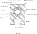
FIG. 5 illustrates an example of a conventional heat receiving tile formed of carbon fiber composite material used for a divertor of a nuclear fusion device, and in particular, illustrates a heat receiving tile suitable for a divertor of a Tokamak type nuclear fusion device. - The divertor of the Tokamak type nuclear fusion device receives the highest heat load in the nuclear fusion device since a kinetic energy of charged particles injected to the divertor is provided thereto as heat. Therefore, the divertor is required to have a function of enduring such a high heat load and removing the heat.
- A
heat receiving tile 50 of the divertor inFIG. 5 is provided with aheat receiving block 51, which is formed of a material having less negative influence on plasma, on its surface facing the plasma in order to protect a cooling structure from a sputtering due to ion radiation or a heat impact caused by plasma disruption. - The
heat receiving block 51 is desired to be formed of a material having a small atomic number which has less negative influence on the plasma, since particles are emitted from the surface of theheat receiving block 51 and mixed in the plasma due to the sputtering or the like, causing decrease in plasma temperature and degradation of confinement performance. A carbon fiber composite material (CFC) is a typical example of such a material, considering heat conductivity. - In the nuclear fusion device which performs a long-term discharge, a surface temperature of a divertor exceeds a service limit temperature of component materials, going beyond heat capacity of the materials configuring the divertor. Accordingly, a
through hole 52 is formed at the center of theheat receiving block 51 and acooling pipe 53 is inserted therethrough. A cooling pipe formed of a copper alloy which has a high heat conductivity and a high strength such as chromium-zirconium copper (CuCrZr), for example is employed as thecooling pipe 53. - Upon operation of the nuclear fusion device, a cooling material such as water is passed though the inside of the
cooling pipe 53 so as to forcibly remove the heat that theheat receiving block 51 received. This prevents theheat receiving block 51 from being damaged exceeding its service limit temperature. - However, there are not good in joinability between the
heat receiving block 51 formed of carbon material such as CFC and thecooling pipe 52 formed of a copper alloy such as CuCrZr, and also there is a great difference in the coefficient of thermal expansion. - Accordingly, in order to efficiently conduct a heat energy received from the plasma to the
cooling pipe 53 and also to absorb the difference in the coefficient of thermal expansion, abuffer material 54 formed of a cupper material such as CuW is interposed between theheat receiving block 51 and thecooling pipe 53. - The
heat receiving block 51 and thebuffer material 54, and thebuffer material 54 and thecooling pipe 53 are metallurgically joined by brazing using a Cu-Mg based or Ti-Cu based joining material with high heat conductivity so as to reduce the resistance of heat transfer as much as possible. Namely, there is a firstbrazing portion 55 between theheat receiving block 51 and thebuffer material 54, and there is a second brazingportion 56 between thebuffer material 54 and thecooling pipe 53. - Note that a
fitting groove 58, through which a rail for fixing theheat receiving tile 50 to other equipment is passed, is formed on a surface of theheat receiving block 51 opposite to aheat receiving surface 57. - Note that, the
heat receiving block 51, thecooling pipe 53, and thebuffer material 54 significantly differ in coefficient of thermal expansion from each other as follows: 1×10⁻⁶ for theheat receiving block 51; 2×10⁻⁵ for thecooling pipe 53; and 1×10⁻⁵ for thebuffer material 54. - Therefore, when the materials shrink in a high temperature processing during the brazing process, especially in a temperature dropping, the
heat receiving block 51 and thebuffer material 54 with small thermal expansion coefficient cannot follow the shrinkage of thecooling pipe 53 with large thermal expansion coefficient, and therefore defects tend to occur at joining parts between them. - As a result, a
crack 59 sometimes occurs in theheat receiving block 51 near the bonding surface of thebuffer material 54, and apeeling 60 sometimes occurs between theheat receiving block 51 and thebuffer material 54. The occurrence of thiscrack 59 and peeling 60 results in the heat conductivity declining and in the cooling efficiency of theheat receiving block 51 declining. - Patent Literature 1 describes a high heat resistant structure component that a graphite portion and a metal portion are coupled to each other via a brazing layer and an intermediate layer is disposed between the metal portion and the brazing layer. Patent Literature 1 describes that this special intermediate layer absorbs the difference in thermal expansion coefficient between the different materials, enabling a solid coupling between the graphite and the metal.
- The high heat resistant structure component of Patent Literature 1 could endure a heat cycle load applied during operation of the nuclear fusion device and prevent an extreme deformation and a material crack of the structure component.
- However, as brazing is performed in a temperature of 850°C to 1900°C, the component sometimes cannot endure a high temperature processing applied during a manufacturing process of the component, and therefore a yield of the product is not considered to be high.
- Patent Literature 1:
Japanese Patent Application Publication No. H08-506315 - Accordingly, an object of the present invention is to provide a heat receiving tile formed of carbon fiber composite material used for a high heat load heat receiving equipment such as a first wall of a nuclear fusion device, the heat receiving tile formed of carbon fiber composite material not including a defect to decline a cooling efficiency such as a peeling between members configuring the heat receiving tile and a crack of the members, and a manufacturing method of the same.
- In order to achieve the above-mentioned object, the present invention provides a heat receiving tile formed of carbon fiber composite material used for a high heat load heat receiving equipment, comprising: a heat receiving block formed of carbon fiber composite material and having a through hole; a cooling pipe inserted through the through hole of the heat receiving block; a buffer material provided to an outer periphery of the cooling pipe; a first brazing portion joining an inner surface of the through hole with an outer surface of the buffer material; a second brazing portion joining an inner surface of the buffer material with an outer surface of the cooling pipe; and a material discontinuous portion extending from a heat receiving surface of the heat receiving block up to at least the outer surface of the buffer material over a full length of the heat receiving block in an axis direction of the through hole.
- Also, it is preferable that the material discontinuous portion is defined by a pair of material surfaces opposed to each other.
- Also, it is preferable that the pair of material surfaces are formed so as to be separated from each other.
- Also, it is preferable that the material discontinuous portion is a slit.
- Also, it is preferable that the pair of material surfaces are in contact with each other at least on a side of the heat receiving surface.
- Also, it is preferable that the material discontinuous portion is formed by making a cut in the heat receiving block in a process of manufacturing the heat receiving tile.
- Also, it is preferable that the cooling pipe is formed of a copper alloy material.
- Also, it is preferable that the high heat load heat receiving equipment is an equipment used as a first wall of a nuclear fusion device.
- Also, it is preferable that the material discontinuous portion extends from the heat receiving surface of the heat receiving block up to the outer surface of the cooling pipe.
- In order to achieve the above-mentioned object, the present invention provides a method of manufacturing a heat receiving tile formed of carbon fiber composite material used for a high heat load heat receiving equipment, comprising the steps of: providing a heat receiving block formed of carbon fiber composite material and having a through hole, the heat receiving block having a slit extending from a heat receiving surface of the heat receiving block up to the through hole over a full length of the heat receiving block in an axis direction of the through hole; disposing a first thin film brazing material to an inner surface of the through hole; disposing a buffer material to an inside of the first thin film brazing material; disposing a second thin film brazing material to an inside of the buffer material; disposing a cooling pipe to an inside of the second thin film brazing material; and brazing an assembly configured by the heat receiving block, the first thin film brazing material, the buffer material, the second thin film brazing material, and the cooling pipe.
- Also, it is preferable that the step of providing the heat receiving block includes a step of forming the slit by making a cut in a material forming the heat receiving block.
- Also, it is preferable that a width of the slit of the heat receiving block is set to a value such that the slit of the heat receiving block is closed at least on a side of the heat receiving surface when a brazing processing has been finished, resulting from a deformation of the heat receiving block caused by a difference between a thermal expansion coefficient of the heat receiving block and a thermal expansion coefficient of the cooling pipe in the step of brazing the assembly.
- Also, it is preferable that the cooling pipe is formed of a copper alloy material.
- Also, it is preferable that the high heat load heat receiving equipment is an equipment used as a first wall of a nuclear fusion device.
- Also, it is preferable that the heat receiving block has a fitting groove on an opposite side of the heat receiving surface, wherein a jig is applied for suppressing a deformation of the fitting groove caused by a deformation of the slit in the step of brazing.
- Also, it is preferable that the buffer material has a slit extending in the axis direction of the though hole, the buffer material being disposed to the inside of the first thin film brazing material such that the slit of the heat receiving block and the slit of the buffer material coincide with each other.
- The present invention can provide a heat receiving tile formed of carbon fiber composite material used for a high heat load heat receiving equipment such as a first wall of a nuclear fusion device, the heat receiving tile formed of carbon fiber composite material not including a defect to decline a cooling efficiency such as a peeling between members configuring the heat receiving tile and a crack of the members, and a manufacturing method of the same.
-
-
FIG. 1 is a longitudinal section view of a heat receiving tile formed of carbon fiber composite material used for a divertor in a nuclear fusion device according to an embodiment of the present invention. -
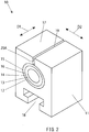
FIG. 2 is a perspective view of the heat receiving tile formed of carbon fiber composite material inFIG. 1 . -
FIG. 3 is an exploded perspective view illustrating a manufacturing method of the heat receiving tile inFIG. 1 . -
FIG. 4 is a longitudinal section view of a heat receiving tile formed of carbon fiber composite material used for a divertor in a nuclear fusion device according to another embodiment of the present invention. -
FIG. 5 is a longitudinal section view of an example of a conventional heat receiving tile formed of carbon fiber composite material used for a divertor in a nuclear fusion devise, illustrating a conventional problem. - Hereunder, a heat receiving tile formed of carbon fiber composite material according to an embodiment of the present invention and a method of manufacturing the same will be described referring to the drawings. Note that a heat receiving tile formed of CFC according to this embodiment is used in a high heat load equipment, in particular it is suitable for a divertor in a tokamak type nuclear fusion device.
- As illustrated in
FIG. 1 andFIG. 2 , a heat receiving tile formed of carbonfiber composite material 10 according to this embodiment is formed of a carbon fiber composite material (CFC) and provided with aheat receiving block 11 having a throughhole 12. Theheat receiving block 11 is generally formed in a substantially rectangular parallelepiped shape. - A cooling
pipe 13 is inserted through the throughhole 12 of theheat receiving block 11. The coolingpipe 13 is preferably configured by a pipe formed of a copper alloy such as chromium-zirconium copper (CuCrZr), for example, which has high heat conductivity and high strength. The inside of the pipe formed of copper alloy is threaded. A cooling material such as water is made to flow inside the coolingpipe 13 upon operation of the nuclear fusion device, thereby cooling theheat receiving block 11 so as to prevent its heat damage. - A
buffer material 14 is provided to the outer surface of the coolingpipe 13. Thebuffer material 14 is preferably formed of a copper alloy such as an oxygen-free copper or copper tungsten (CuW). Thebuffer material 14 serves to absorb a thermal expansion difference between the coolingpipe 13 and theheat receiving block 11 to some extent. - A
first brazing portion 15 is formed between the inner surface of the throughhole 12 of theheat receiving block 11 and the outer surface of thebuffer material 14 so as to join them together. Also, asecond brazing portion 16 is formed between the inner surface of thebuffer material 14 and the outer surface of the coolingpipe 13 so as to join them together. Thefirst brazing portion 15 and thesecond brazing portion 16 are preferably formed of the Cu-Mg based or Ti-Cu based joining material with high heat conductivity. - Further, the
heat receiving tile 10 formed of CFC according to this embodiment has a slit (material discontinuous portion) 19 which extends from aheat receiving surface 17 of theheat receiving block 11 up to the outer surface of thebuffer material 14 over the full length of theheat receiving block 11 in an axis direction D1 (FIG. 2 ) of the throughhole 12 of theheat receiving block 11. - The
slit 19 is defined by a pair ofmaterial surfaces slit 19 is preferably formed in a center portion in a width direction D2 (FIG. 2 ) orthogonal to the axis direction D1 in theheat receiving surface 17 of theheat receiving block 11. - Next, a method of manufacturing the
heat receiving tile 10 formed of CFC according to an embodiment of the present invention will be described referring toFIG. 3 . - The manufacturing method according to this embodiment is provided with a process of providing the
heat receiving block 11 formed of the carbon fiber composite material (CFC) and having the throughhole 12. Theheat receiving block 11 has aslit 19A which extends from theheat receiving surface 17 up to the throughhole 12 of theheat receiving block 11 over the full length of theheat receiving block 11 in the axis direction D1 of the throughhole 12. Theslit 19A is formed by making a cut in a material which forms theheat receiving block 11. - A first thin
film brazing material 15 is disposed inside the throughhole 12 of theheat receiving block 11. The first thinfilm brazing material 15 has aslit 19B extending in the axis direction D1 of the throughhole 12, and is disposed such that theslit 19B coincides with theslit 19A of theheat receiving block 11. - A
buffer material 14 is disposed inside the first thinfilm brazing material 15. - A second thin
film brazing material 16 is disposed inside thebuffer material 14. - A cooling
pipe 13 is disposed inside the second thinfilm brazing material 15. The coolingpipe 13 is disposed so as to penetrate each throughhole 12 of a plurality of heat receiving blocks 11. - An assembly configured by the
heat receiving block 11, the first thinfilm brazing material 15, thebuffer material 14, the second thinfilm brazing material 16, and the coolingpipe 13 is vacuum-brazed and applied an aging processing. - At this time, in the conventional heat receiving tile in
FIG. 5 , the heat receiving block and the buffer material with small thermal expansion coefficient cannot follow the shrinkage of the cooling pipe with large thermal expansion coefficient when the materials shrink in a high temperature processing during the brazing process, especially in a temperature dropping, and therefore defects tend to occur at joining parts between them. - In contrast, in this embodiment, the
slits heat receiving block 11 and the first thinfilm brazing material 15 respectively, and therefore thebuffer material 14 joined with the outer surface of the coolingpipe 13 is deformed following the coolingpipe 13 and also theheat receiving block 11 is deformed following thebuffer material 14 in the same manner even when the coolingpipe 13 shrinks largely in the temperature dropping. - This enables the difference in thermal expansion coefficient between respective members to be absorbed as a circumferential displacement of each member, thereby enabling prevention of excessive stress occurring in joining surfaces between respective members upon shrinkage of the cooling
pipe 13 in the temperature dropping and also enabling prevention of a crack of theheat receiving block 11 in the vicinity of the joining surface and peeling of joining surfaces between respective members. - Thus, degradation of cooling efficiency of the
heat receiving tile 10 can be prevented by preventing the peeling of respective members configuring theheat receiving tile 10 and the crack of the members in this manner. - In particular, in the
heat receiving tile 10 formed of CFC according to this embodiment, theslit 19 is formed on the side of theheat receiving surface 17 in an operation of the nuclear fusion device, and therefore joining of respective members on the side of theheat receiving surface 17 can be more reliable. Accordingly, a sufficient heat conduction efficiency can be ensured on the side of theheat receiving surface 17 where an especially high cooling efficiency is required, and theheat receiving block 11 can be sufficiently cooled during operation of the nuclear fusion device. - Also, in this embodiment, the inside of the pipe formed of copper alloy configuring the cooling
pipe 13 is threaded. Therefore, a pipe wall thickness is larger compared to a non-threaded normal pipe and also the wall thickness is discontinuous, resulting in a shrinking force of the pipe upon brazing being larger and more uneven than a normal piping. - Therefore, brazing becomes more difficult than the normal piping, while a brazing processing can be performed properly even when the inside of the pipe formed of copper alloy configuring the cooling
pipe 13 is threaded, by absorbing deformation of each member upon brazing by means of theslit 19 as mentioned above. - Next, a heat receiving tile formed of CFC according to another embodiment of the present invention and a manufacturing method of the same will be described referring to
FIG. 4 . - As illustrated in
FIG. 4 , in aheat receiving tile 40 formed of CFC according to this embodiment, itsslit 19 is closed on the side of theheat receiving surface 17 of theheat receiving block 11. - In a manufacturing method of the
heat receiving tile 40 according to this embodiment, a width of theslit 19A (FIG. 3 ) of theheat receiving block 11 before the brazing processing is set to a value that theslit 19 of theheat receiving block 11 is closed at least on the side of theheat receiving surface 17 when the brazing processing has been finished, resulting from deformation of theheat receiving block 11 caused by the difference between the thermal expansion coefficient of theheat receiving block 11 and the thermal expansion coefficient of the coolingpipe 13 in the process of vacuum-brazing and applying an aging processing to the assembly configured by theheat receiving block 11, and the like. - Namely, the cooling
pipe 13 expanded in the high temperature processing in brazing shrinks largely in the temperature dropping after that, while theheat receiving block 11 formed of CFC has a smaller shrinkage compared to the coolingpipe 13. A stress works on theheat receiving block 11 resulting from the difference in shrinkage between the both and theheat receiving block 11 is thereby deformed in a direction of closing theslit 19 on the side of theheat receiving surface 17 as illustrated inFIG. 4 . - Thus, a width of a
slit 19A of theheat receiving block 11 before the brazing processing is set such that the width of theslit 19A disappears in completion on the side of theheat receiving surface 17, considering a deformation amount of theheat receiving block 11 in the temperature dropping. - According to this embodiment, the
slit 19 of the completedheat receiving tile 40 is closed on the side of theheat receiving surface 17 of theheat receiving block 11, and therefore a heat radiation in an operation of the nuclear fusion device can be surely prevented from directly reaching the coolingpipe 13 via theslit 19. - Also, closing of the
slit 19 in the brazing processing induces a deformation of thefitting groove 18 disposed on the opposite side of theslit 19, which will be addressed by applying a jig for fixing a width of the subject portion and a carbon sheet as a buffer material, which is softer and more deformable than a material, between the jig and a product. - As a variation of each embodiment above, a slit can be formed in the
buffer material 14 as well corresponding to theslit 19 of theheat receiving block 11. Namely, in this variation, thebuffer material 14 has a slit extending in the axis direction of the throughhole 12 of theheat receiving block 11, and the slit of thebuffer material 14 and theslit 19 of theheat receiving block 11 coincide with each other. - Note that, although the heat receiving tile suitable for the divertor configuring the first wall of the Tokamak type nuclear fusion device is described in each embodiment and its variation above, the heat receiving tile formed of CFC according to the present invention is not limited to the application for the first wall of the nuclear fusion device and can also be broadly applied to a heat receiving tile which is formed by metallurgically joining a cooling pipe to a heat receiving block formed of CFC.
-
- 10, 40 ...
- heat receiving tile formed of CFC
- 11 ...
- heat receiving block
- 12 ...
- through hole
- 13 ...
- cooling pipe
- 14 ...
- buffer material
- 15 ...
- first brazing portion (first brazing thin film)
- 16 ...
- second brazing portion (second brazing thin film)
- 17 ...
- heat receiving surface
- 18 ...
- fitting groove
- 19, 19A, 19B ...
- slit (material discontinuous portion)
- 20A, 20B ...
- material surface
Claims (16)
- A heat receiving tile formed of carbon fiber composite material used for a high heat load heat receiving equipment, comprising:a heat receiving block formed of a carbon fiber composite material and having a through hole;a cooling pipe inserted through the through hole of the heat receiving block;a buffer material provided to an outer periphery of the cooling pipe;a first brazing portion joining an inner surface of the through hole with an outer surface of the buffer material;a second brazing portion joining an inner surface of the buffer material with an outer surface of the cooling pipe; anda material discontinuous portion extending from a heat receiving surface of the heat receiving block up to at least the outer surface of the buffer material over a full length of the heat receiving block in an axis direction of the through hole.
- The heat receiving tile formed of carbon fiber composite material according to claim 1, wherein the material discontinuous portion is defined by a pair of material surfaces opposed to each other.
- The heat receiving tile formed of carbon fiber composite material according to claim 2, wherein the pair of material surfaces are formed so as to be separated from each other.
- The heat receiving tile formed of carbon fiber composite material according to claim 3, wherein the material discontinuous portion is a slit.
- The heat receiving tile formed of carbon fiber composite material according to claim 2, wherein the pair of material surfaces are in contact with each other at least on a side of the heat receiving surface.
- The heat receiving tile formed of carbon fiber composite material according to any one of claims 1 to 5, wherein the material discontinuous portion is formed by making a cut in the heat receiving block in a process of manufacturing the heat receiving tile.
- The heat receiving tile formed of carbon fiber composite material according to any one of claims 1 to 6, wherein the cooling pipe is formed of a copper alloy material.
- The heat receiving tile formed of carbon fiber composite material according to any one of claims 1 to 7, wherein the high heat load heat receiving equipment is an equipment used as a first wall of a nuclear fusion device.
- The heat receiving tile formed of carbon fiber composite material according to any one of claims 1 to 8, wherein the material discontinuous portion extends from the heat receiving surface of the heat receiving block up to the outer surface of the cooling pipe.
- A method of manufacturing a heat receiving tile formed of carbon fiber composite material used for a high heat load heat receiving equipment comprising the steps of:providing a heat receiving block formed of a carbon fiber composite material and having a through hole, the heat receiving block having a slit extending from a heat receiving surface of the heat receiving block up to the through hole over a full length of the heat receiving block in an axis direction of the through hole;disposing a first thin film brazing material on an inner surface of the through hole;disposing a buffer material on an inside of the first thin film brazing material;disposing a second thin film brazing material on an inside of the buffer material;disposing a cooling pipe to an inside of the second thin film brazing material; andbrazing an assembly configured by the heat receiving block, the first thin film brazing material, the buffer material, the second thin film brazing material, and the cooling pipe.
- The method of manufacturing a heat receiving tile formed of carbon fiber composite material according to claim 10, wherein the step of providing the heat receiving block includes a step of forming the slit by making a cut in a material forming the heat receiving block.
- The method of manufacturing a heat receiving tile formed of carbon fiber composite material according to claim 10 or 11, wherein a width of the slit of the heat receiving block is set to a value such that the slit of the heat receiving block is closed at least on a side of the heat receiving surface when a brazing processing has been finished, resulting from a deformation of the heat receiving block caused by a difference between a thermal expansion coefficient of the heat receiving block and a thermal expansion coefficient of the cooling pipe in the step of brazing the assembly.
- The method of manufacturing a heat receiving tile formed of carbon fiber composite material according to any one of claims 10 to 12, wherein the cooling pipe is formed of a copper alloy material.
- The method of manufacturing a heat receiving tile formed of carbon fiber composite material according to any one of claims 10 to 13, wherein the high heat load heat receiving equipment is an equipment used as a first wall of a nuclear fusion device.
- The method of manufacturing a heat receiving tile formed of carbon fiber composite material according to any one of claims 10 to 14, wherein the heat receiving block has a fitting groove on an opposite side of the heat receiving surface, and wherein a jig is applied for suppressing a deformation of the fitting groove caused by a deformation of the slit in the step of brazing.
- The method of manufacturing a heat receiving tile formed of carbon fiber composite material according to any one of claims 10 to 15, wherein the buffer material has a slit extending in the axis direction of the though hole, the buffer material being disposed on the inside of the first thin film brazing material such that the slit of the heat receiving block and the slit of the buffer material coincide with each other.
Applications Claiming Priority (2)
| Application Number | Priority Date | Filing Date | Title |
|---|---|---|---|
| JP2014020421A JP6403040B2 (en) | 2014-02-05 | 2014-02-05 | Carbon fiber composite heat-receiving tile and method for manufacturing the same |
| PCT/JP2015/053212 WO2015119187A1 (en) | 2014-02-05 | 2015-02-05 | Carbon-fiber-composite heat-collecting tile and method for producing same |
Publications (3)
| Publication Number | Publication Date |
|---|---|
| EP3104368A1 true EP3104368A1 (en) | 2016-12-14 |
| EP3104368A4 EP3104368A4 (en) | 2017-09-13 |
| EP3104368B1 EP3104368B1 (en) | 2018-11-21 |
Family
ID=53777988
Family Applications (1)
| Application Number | Title | Priority Date | Filing Date |
|---|---|---|---|
| EP15747046.9A Not-in-force EP3104368B1 (en) | 2014-02-05 | 2015-02-05 | Carbon-fiber-composite heat-collecting tile and method for producing same |
Country Status (4)
| Country | Link |
|---|---|
| US (1) | US10024605B2 (en) |
| EP (1) | EP3104368B1 (en) |
| JP (1) | JP6403040B2 (en) |
| WO (1) | WO2015119187A1 (en) |
Cited By (1)
| Publication number | Priority date | Publication date | Assignee | Title |
|---|---|---|---|---|
| CN111312411A (en) * | 2018-12-11 | 2020-06-19 | 核工业西南物理研究院 | Method for preventing plasma rupture by jet injection of liquefied noble gas |
Families Citing this family (3)
| Publication number | Priority date | Publication date | Assignee | Title |
|---|---|---|---|---|
| US10267576B2 (en) * | 2016-01-28 | 2019-04-23 | L & M Radiator, Inc. | Heat exchanger with tanks, tubes and retainer |
| EA202191198A1 (en) * | 2018-11-01 | 2021-09-14 | Этомос Ньюклиар Энд Спейс Корпорейшн | SYSTEM OF RADIATOR RIBS MADE OF CARBON FIBER |
| CN110047599A (en) * | 2019-03-21 | 2019-07-23 | 中国科学院合肥物质科学研究院 | A kind of insulation system for the cold screen of fusion facility |
Family Cites Families (8)
| Publication number | Priority date | Publication date | Assignee | Title |
|---|---|---|---|---|
| JPH0235097U (en) * | 1988-08-31 | 1990-03-06 | ||
| AT399473B (en) | 1993-09-14 | 1995-05-26 | Plansee Metallwerk | THERMALLY HIGH-STRENGTH COMPONENT |
| JPH07167972A (en) * | 1993-12-15 | 1995-07-04 | Toshiba Corp | First wall of fusion device |
| AT8158U1 (en) * | 2004-10-27 | 2006-02-15 | Plansee Ag | MONOBLOCK COOLING COMPONENT |
| AT8485U1 (en) | 2005-03-22 | 2006-08-15 | Plansee Se | FIRST WALL COMPONENT FOR FUSION REACTOR |
| AT9173U1 (en) * | 2005-12-06 | 2007-05-15 | Plansee Se | FIRST WALL COMPONENT WITH RINGSEGMENT |
| JP2011122883A (en) * | 2009-12-09 | 2011-06-23 | Kawasaki Heavy Ind Ltd | Method of manufacturing high-temperature load equipment by metallugically joining carbon material with copper-alloy material |
| JP6173767B2 (en) * | 2013-05-16 | 2017-08-02 | 川崎重工業株式会社 | Heat-receiving tile made of carbon fiber composite material and manufacturing method thereof |
-
2014
- 2014-02-05 JP JP2014020421A patent/JP6403040B2/en not_active Expired - Fee Related
-
2015
- 2015-02-05 WO PCT/JP2015/053212 patent/WO2015119187A1/en not_active Ceased
- 2015-02-05 US US15/117,009 patent/US10024605B2/en not_active Expired - Fee Related
- 2015-02-05 EP EP15747046.9A patent/EP3104368B1/en not_active Not-in-force
Cited By (1)
| Publication number | Priority date | Publication date | Assignee | Title |
|---|---|---|---|---|
| CN111312411A (en) * | 2018-12-11 | 2020-06-19 | 核工业西南物理研究院 | Method for preventing plasma rupture by jet injection of liquefied noble gas |
Also Published As
| Publication number | Publication date |
|---|---|
| EP3104368B1 (en) | 2018-11-21 |
| US20170167802A1 (en) | 2017-06-15 |
| JP2015148475A (en) | 2015-08-20 |
| WO2015119187A1 (en) | 2015-08-13 |
| JP6403040B2 (en) | 2018-10-10 |
| EP3104368A4 (en) | 2017-09-13 |
| US10024605B2 (en) | 2018-07-17 |
Similar Documents
| Publication | Publication Date | Title |
|---|---|---|
| EP2998962B1 (en) | Heat receiving tile formed from carbon fiber composite material and method for producing same | |
| EP3104368B1 (en) | Carbon-fiber-composite heat-collecting tile and method for producing same | |
| CN107705823B (en) | Cooling structure suitable for first wall of magnetic confinement nuclear fusion device | |
| JP3025441B2 (en) | Method for manufacturing first cooling wall of fusion reactor | |
| CN103886919B (en) | Lamination is utilized to improve the method for fusion reactor inwall anti-plasma irradiation behaviour | |
| CN113547194A (en) | Connecting method of tungsten copper module | |
| US20130168054A1 (en) | Heat pipe and method for manufacturing the same | |
| US20160151965A1 (en) | Coupling Components to One Another Utilizing Electromagnetic Energy | |
| EP3053689B1 (en) | Brazed joints and methods of forming brazed joints | |
| EP2620250A1 (en) | Heat treatment method for branch pipe welded portion | |
| CN109478610B (en) | Method and apparatus for sealing of metal | |
| JP5314120B2 (en) | Fusion reactor divertor curvature part machining method | |
| JP6543728B2 (en) | Cylindrical target | |
| EP3069352B1 (en) | Component with variable geometry for a large structure and assembly method | |
| US11493164B2 (en) | Structure formed by temperature difference, method of forming the structure, and lightweight rigid assembly comprising the structure | |
| CN116592141A (en) | An ultra-high vacuum elastic energy storage metal sealing ring and its manufacturing method | |
| CN112081811A (en) | All-metal locknut and processing method thereof | |
| Igitkhanov et al. | Effect of thermal loads on different modules of demo PFCs | |
| JPH07167972A (en) | First wall of fusion device | |
| CN120480334A (en) | Low-expansion light heat conduction chain and processing method thereof | |
| Sato et al. | Proposal of hot-pressed, rod-shaped tungsten armor concept for ITER divertor and its high-heat-flux performances | |
| JP6715125B2 (en) | Heat exchanger, fusion reactor and neutral particle injection heating device | |
| CN121720829A (en) | Method for clamping ceramic pipe based on shape memory alloy pipe sleeve | |
| JPH03176692A (en) | Structure of diverter plate | |
| JPH07100358B2 (en) | Composite material consisting of graphite and copper |
Legal Events
| Date | Code | Title | Description |
|---|---|---|---|
| PUAI | Public reference made under article 153(3) epc to a published international application that has entered the european phase |
Free format text: ORIGINAL CODE: 0009012 |
|
| STAA | Information on the status of an ep patent application or granted ep patent |
Free format text: STATUS: REQUEST FOR EXAMINATION WAS MADE |
|
| 17P | Request for examination filed |
Effective date: 20160902 |
|
| AK | Designated contracting states |
Kind code of ref document: A1 Designated state(s): AL AT BE BG CH CY CZ DE DK EE ES FI FR GB GR HR HU IE IS IT LI LT LU LV MC MK MT NL NO PL PT RO RS SE SI SK SM TR |
|
| AX | Request for extension of the european patent |
Extension state: BA ME |
|
| DAX | Request for extension of the european patent (deleted) | ||
| A4 | Supplementary search report drawn up and despatched |
Effective date: 20170816 |
|
| RIC1 | Information provided on ipc code assigned before grant |
Ipc: B23K 1/19 20060101ALI20170809BHEP Ipc: G21B 1/13 20060101ALI20170809BHEP Ipc: F28F 21/02 20060101ALI20170809BHEP Ipc: F28F 19/02 20060101ALI20170809BHEP Ipc: G21B 1/11 20060101AFI20170809BHEP Ipc: B23K 1/00 20060101ALI20170809BHEP Ipc: G21B 1/17 20060101ALI20170809BHEP Ipc: F28F 21/08 20060101ALI20170809BHEP |
|
| GRAP | Despatch of communication of intention to grant a patent |
Free format text: ORIGINAL CODE: EPIDOSNIGR1 |
|
| STAA | Information on the status of an ep patent application or granted ep patent |
Free format text: STATUS: GRANT OF PATENT IS INTENDED |
|
| INTG | Intention to grant announced |
Effective date: 20180620 |
|
| GRAS | Grant fee paid |
Free format text: ORIGINAL CODE: EPIDOSNIGR3 |
|
| GRAA | (expected) grant |
Free format text: ORIGINAL CODE: 0009210 |
|
| STAA | Information on the status of an ep patent application or granted ep patent |
Free format text: STATUS: THE PATENT HAS BEEN GRANTED |
|
| AK | Designated contracting states |
Kind code of ref document: B1 Designated state(s): AL AT BE BG CH CY CZ DE DK EE ES FI FR GB GR HR HU IE IS IT LI LT LU LV MC MK MT NL NO PL PT RO RS SE SI SK SM TR |
|
| REG | Reference to a national code |
Ref country code: CH Ref legal event code: EP |
|
| REG | Reference to a national code |
Ref country code: IE Ref legal event code: FG4D |
|
| REG | Reference to a national code |
Ref country code: DE Ref legal event code: R096 Ref document number: 602015020032 Country of ref document: DE |
|
| REG | Reference to a national code |
Ref country code: AT Ref legal event code: REF Ref document number: 1068483 Country of ref document: AT Kind code of ref document: T Effective date: 20181215 |
|
| REG | Reference to a national code |
Ref country code: NL Ref legal event code: MP Effective date: 20181121 |
|
| PG25 | Lapsed in a contracting state [announced via postgrant information from national office to epo] |
Ref country code: ES Free format text: LAPSE BECAUSE OF FAILURE TO SUBMIT A TRANSLATION OF THE DESCRIPTION OR TO PAY THE FEE WITHIN THE PRESCRIBED TIME-LIMIT Effective date: 20181121 Ref country code: IS Free format text: LAPSE BECAUSE OF FAILURE TO SUBMIT A TRANSLATION OF THE DESCRIPTION OR TO PAY THE FEE WITHIN THE PRESCRIBED TIME-LIMIT Effective date: 20190321 Ref country code: NO Free format text: LAPSE BECAUSE OF FAILURE TO SUBMIT A TRANSLATION OF THE DESCRIPTION OR TO PAY THE FEE WITHIN THE PRESCRIBED TIME-LIMIT Effective date: 20190221 Ref country code: HR Free format text: LAPSE BECAUSE OF FAILURE TO SUBMIT A TRANSLATION OF THE DESCRIPTION OR TO PAY THE FEE WITHIN THE PRESCRIBED TIME-LIMIT Effective date: 20181121 Ref country code: LT Free format text: LAPSE BECAUSE OF FAILURE TO SUBMIT A TRANSLATION OF THE DESCRIPTION OR TO PAY THE FEE WITHIN THE PRESCRIBED TIME-LIMIT Effective date: 20181121 Ref country code: BG Free format text: LAPSE BECAUSE OF FAILURE TO SUBMIT A TRANSLATION OF THE DESCRIPTION OR TO PAY THE FEE WITHIN THE PRESCRIBED TIME-LIMIT Effective date: 20190221 Ref country code: FI Free format text: LAPSE BECAUSE OF FAILURE TO SUBMIT A TRANSLATION OF THE DESCRIPTION OR TO PAY THE FEE WITHIN THE PRESCRIBED TIME-LIMIT Effective date: 20181121 Ref country code: LV Free format text: LAPSE BECAUSE OF FAILURE TO SUBMIT A TRANSLATION OF THE DESCRIPTION OR TO PAY THE FEE WITHIN THE PRESCRIBED TIME-LIMIT Effective date: 20181121 |
|
| PG25 | Lapsed in a contracting state [announced via postgrant information from national office to epo] |
Ref country code: RS Free format text: LAPSE BECAUSE OF FAILURE TO SUBMIT A TRANSLATION OF THE DESCRIPTION OR TO PAY THE FEE WITHIN THE PRESCRIBED TIME-LIMIT Effective date: 20181121 Ref country code: AL Free format text: LAPSE BECAUSE OF FAILURE TO SUBMIT A TRANSLATION OF THE DESCRIPTION OR TO PAY THE FEE WITHIN THE PRESCRIBED TIME-LIMIT Effective date: 20181121 Ref country code: SE Free format text: LAPSE BECAUSE OF FAILURE TO SUBMIT A TRANSLATION OF THE DESCRIPTION OR TO PAY THE FEE WITHIN THE PRESCRIBED TIME-LIMIT Effective date: 20181121 Ref country code: PT Free format text: LAPSE BECAUSE OF FAILURE TO SUBMIT A TRANSLATION OF THE DESCRIPTION OR TO PAY THE FEE WITHIN THE PRESCRIBED TIME-LIMIT Effective date: 20190321 Ref country code: GR Free format text: LAPSE BECAUSE OF FAILURE TO SUBMIT A TRANSLATION OF THE DESCRIPTION OR TO PAY THE FEE WITHIN THE PRESCRIBED TIME-LIMIT Effective date: 20190222 Ref country code: NL Free format text: LAPSE BECAUSE OF FAILURE TO SUBMIT A TRANSLATION OF THE DESCRIPTION OR TO PAY THE FEE WITHIN THE PRESCRIBED TIME-LIMIT Effective date: 20181121 |
|
| PG25 | Lapsed in a contracting state [announced via postgrant information from national office to epo] |
Ref country code: PL Free format text: LAPSE BECAUSE OF FAILURE TO SUBMIT A TRANSLATION OF THE DESCRIPTION OR TO PAY THE FEE WITHIN THE PRESCRIBED TIME-LIMIT Effective date: 20181121 Ref country code: DK Free format text: LAPSE BECAUSE OF FAILURE TO SUBMIT A TRANSLATION OF THE DESCRIPTION OR TO PAY THE FEE WITHIN THE PRESCRIBED TIME-LIMIT Effective date: 20181121 Ref country code: IT Free format text: LAPSE BECAUSE OF FAILURE TO SUBMIT A TRANSLATION OF THE DESCRIPTION OR TO PAY THE FEE WITHIN THE PRESCRIBED TIME-LIMIT Effective date: 20181121 Ref country code: CZ Free format text: LAPSE BECAUSE OF FAILURE TO SUBMIT A TRANSLATION OF THE DESCRIPTION OR TO PAY THE FEE WITHIN THE PRESCRIBED TIME-LIMIT Effective date: 20181121 |
|
| REG | Reference to a national code |
Ref country code: DE Ref legal event code: R097 Ref document number: 602015020032 Country of ref document: DE |
|
| PG25 | Lapsed in a contracting state [announced via postgrant information from national office to epo] |
Ref country code: EE Free format text: LAPSE BECAUSE OF FAILURE TO SUBMIT A TRANSLATION OF THE DESCRIPTION OR TO PAY THE FEE WITHIN THE PRESCRIBED TIME-LIMIT Effective date: 20181121 Ref country code: SM Free format text: LAPSE BECAUSE OF FAILURE TO SUBMIT A TRANSLATION OF THE DESCRIPTION OR TO PAY THE FEE WITHIN THE PRESCRIBED TIME-LIMIT Effective date: 20181121 Ref country code: RO Free format text: LAPSE BECAUSE OF FAILURE TO SUBMIT A TRANSLATION OF THE DESCRIPTION OR TO PAY THE FEE WITHIN THE PRESCRIBED TIME-LIMIT Effective date: 20181121 Ref country code: SK Free format text: LAPSE BECAUSE OF FAILURE TO SUBMIT A TRANSLATION OF THE DESCRIPTION OR TO PAY THE FEE WITHIN THE PRESCRIBED TIME-LIMIT Effective date: 20181121 |
|
| REG | Reference to a national code |
Ref country code: DE Ref legal event code: R119 Ref document number: 602015020032 Country of ref document: DE |
|
| PLBE | No opposition filed within time limit |
Free format text: ORIGINAL CODE: 0009261 |
|
| STAA | Information on the status of an ep patent application or granted ep patent |
Free format text: STATUS: NO OPPOSITION FILED WITHIN TIME LIMIT |
|
| REG | Reference to a national code |
Ref country code: CH Ref legal event code: PL |
|
| GBPC | Gb: european patent ceased through non-payment of renewal fee |
Effective date: 20190221 |
|
| 26N | No opposition filed |
Effective date: 20190822 |
|
| PG25 | Lapsed in a contracting state [announced via postgrant information from national office to epo] |
Ref country code: LU Free format text: LAPSE BECAUSE OF NON-PAYMENT OF DUE FEES Effective date: 20190205 Ref country code: MC Free format text: LAPSE BECAUSE OF FAILURE TO SUBMIT A TRANSLATION OF THE DESCRIPTION OR TO PAY THE FEE WITHIN THE PRESCRIBED TIME-LIMIT Effective date: 20181121 Ref country code: SI Free format text: LAPSE BECAUSE OF FAILURE TO SUBMIT A TRANSLATION OF THE DESCRIPTION OR TO PAY THE FEE WITHIN THE PRESCRIBED TIME-LIMIT Effective date: 20181121 |
|
| REG | Reference to a national code |
Ref country code: BE Ref legal event code: MM Effective date: 20190228 |
|
| REG | Reference to a national code |
Ref country code: IE Ref legal event code: MM4A |
|
| PG25 | Lapsed in a contracting state [announced via postgrant information from national office to epo] |
Ref country code: CH Free format text: LAPSE BECAUSE OF NON-PAYMENT OF DUE FEES Effective date: 20190228 Ref country code: LI Free format text: LAPSE BECAUSE OF NON-PAYMENT OF DUE FEES Effective date: 20190228 |
|
| PG25 | Lapsed in a contracting state [announced via postgrant information from national office to epo] |
Ref country code: GB Free format text: LAPSE BECAUSE OF NON-PAYMENT OF DUE FEES Effective date: 20190221 Ref country code: IE Free format text: LAPSE BECAUSE OF NON-PAYMENT OF DUE FEES Effective date: 20190205 Ref country code: DE Free format text: LAPSE BECAUSE OF NON-PAYMENT OF DUE FEES Effective date: 20190903 |
|
| PG25 | Lapsed in a contracting state [announced via postgrant information from national office to epo] |
Ref country code: BE Free format text: LAPSE BECAUSE OF NON-PAYMENT OF DUE FEES Effective date: 20190228 |
|
| PG25 | Lapsed in a contracting state [announced via postgrant information from national office to epo] |
Ref country code: TR Free format text: LAPSE BECAUSE OF FAILURE TO SUBMIT A TRANSLATION OF THE DESCRIPTION OR TO PAY THE FEE WITHIN THE PRESCRIBED TIME-LIMIT Effective date: 20181121 |
|
| PG25 | Lapsed in a contracting state [announced via postgrant information from national office to epo] |
Ref country code: MT Free format text: LAPSE BECAUSE OF NON-PAYMENT OF DUE FEES Effective date: 20190205 |
|
| REG | Reference to a national code |
Ref country code: AT Ref legal event code: UEP Ref document number: 1068483 Country of ref document: AT Kind code of ref document: T Effective date: 20181121 |
|
| PGFP | Annual fee paid to national office [announced via postgrant information from national office to epo] |
Ref country code: FR Payment date: 20210113 Year of fee payment: 7 |
|
| PG25 | Lapsed in a contracting state [announced via postgrant information from national office to epo] |
Ref country code: CY Free format text: LAPSE BECAUSE OF FAILURE TO SUBMIT A TRANSLATION OF THE DESCRIPTION OR TO PAY THE FEE WITHIN THE PRESCRIBED TIME-LIMIT Effective date: 20181121 |
|
| PGFP | Annual fee paid to national office [announced via postgrant information from national office to epo] |
Ref country code: AT Payment date: 20210125 Year of fee payment: 7 |
|
| PG25 | Lapsed in a contracting state [announced via postgrant information from national office to epo] |
Ref country code: HU Free format text: LAPSE BECAUSE OF FAILURE TO SUBMIT A TRANSLATION OF THE DESCRIPTION OR TO PAY THE FEE WITHIN THE PRESCRIBED TIME-LIMIT; INVALID AB INITIO Effective date: 20150205 |
|
| REG | Reference to a national code |
Ref country code: AT Ref legal event code: PC Ref document number: 1068483 Country of ref document: AT Kind code of ref document: T Owner name: ATOX CO., LTD., JP Effective date: 20220127 |
|
| PG25 | Lapsed in a contracting state [announced via postgrant information from national office to epo] |
Ref country code: MK Free format text: LAPSE BECAUSE OF FAILURE TO SUBMIT A TRANSLATION OF THE DESCRIPTION OR TO PAY THE FEE WITHIN THE PRESCRIBED TIME-LIMIT Effective date: 20181121 |
|
| REG | Reference to a national code |
Ref country code: AT Ref legal event code: MM01 Ref document number: 1068483 Country of ref document: AT Kind code of ref document: T Effective date: 20220205 |
|
| PG25 | Lapsed in a contracting state [announced via postgrant information from national office to epo] |
Ref country code: AT Free format text: LAPSE BECAUSE OF NON-PAYMENT OF DUE FEES Effective date: 20220205 |
|
| PG25 | Lapsed in a contracting state [announced via postgrant information from national office to epo] |
Ref country code: FR Free format text: LAPSE BECAUSE OF NON-PAYMENT OF DUE FEES Effective date: 20220228 |