EP3103993A1 - Control device for internal combustion engine - Google Patents
Control device for internal combustion engine Download PDFInfo
- Publication number
- EP3103993A1 EP3103993A1 EP16171856.4A EP16171856A EP3103993A1 EP 3103993 A1 EP3103993 A1 EP 3103993A1 EP 16171856 A EP16171856 A EP 16171856A EP 3103993 A1 EP3103993 A1 EP 3103993A1
- Authority
- EP
- European Patent Office
- Prior art keywords
- mode
- fuel ratio
- air
- egr
- lean
- Prior art date
- Legal status (The legal status is an assumption and is not a legal conclusion. Google has not performed a legal analysis and makes no representation as to the accuracy of the status listed.)
- Granted
Links
- 238000002485 combustion reaction Methods 0.000 title claims description 34
- 239000000446 fuel Substances 0.000 claims abstract description 145
- 230000001052 transient effect Effects 0.000 claims abstract description 45
- 239000003054 catalyst Substances 0.000 claims description 31
- 230000003197 catalytic effect Effects 0.000 claims description 19
- 238000011144 upstream manufacturing Methods 0.000 claims description 14
- QGZKDVFQNNGYKY-UHFFFAOYSA-N Ammonia Chemical compound N QGZKDVFQNNGYKY-UHFFFAOYSA-N 0.000 description 62
- 229910000069 nitrogen hydride Inorganic materials 0.000 description 60
- 238000002347 injection Methods 0.000 description 53
- 239000007924 injection Substances 0.000 description 53
- 239000007789 gas Substances 0.000 description 48
- 238000001179 sorption measurement Methods 0.000 description 20
- 230000007423 decrease Effects 0.000 description 18
- 238000007254 oxidation reaction Methods 0.000 description 18
- 230000003647 oxidation Effects 0.000 description 17
- QVGXLLKOCUKJST-UHFFFAOYSA-N atomic oxygen Chemical compound [O] QVGXLLKOCUKJST-UHFFFAOYSA-N 0.000 description 13
- 239000001301 oxygen Substances 0.000 description 13
- 229910052760 oxygen Inorganic materials 0.000 description 13
- 239000003638 chemical reducing agent Substances 0.000 description 12
- 238000000034 method Methods 0.000 description 5
- 238000000746 purification Methods 0.000 description 5
- 230000001687 destabilization Effects 0.000 description 4
- 230000000694 effects Effects 0.000 description 4
- 230000006866 deterioration Effects 0.000 description 3
- 230000005540 biological transmission Effects 0.000 description 2
- 230000003134 recirculating effect Effects 0.000 description 2
- 230000002000 scavenging effect Effects 0.000 description 2
- 229910002651 NO3 Inorganic materials 0.000 description 1
- NHNBFGGVMKEFGY-UHFFFAOYSA-N Nitrate Chemical compound [O-][N+]([O-])=O NHNBFGGVMKEFGY-UHFFFAOYSA-N 0.000 description 1
- XSQUKJJJFZCRTK-UHFFFAOYSA-N Urea Chemical compound NC(N)=O XSQUKJJJFZCRTK-UHFFFAOYSA-N 0.000 description 1
- 229910021529 ammonia Inorganic materials 0.000 description 1
- 239000004202 carbamide Substances 0.000 description 1
- 238000006243 chemical reaction Methods 0.000 description 1
- 230000006835 compression Effects 0.000 description 1
- 238000007906 compression Methods 0.000 description 1
- 239000010789 controlled waste Substances 0.000 description 1
- 238000001816 cooling Methods 0.000 description 1
- 230000001590 oxidative effect Effects 0.000 description 1
- 230000001360 synchronised effect Effects 0.000 description 1
- 230000007704 transition Effects 0.000 description 1
- 239000002699 waste material Substances 0.000 description 1
Images


Classifications
-
- F—MECHANICAL ENGINEERING; LIGHTING; HEATING; WEAPONS; BLASTING
- F02—COMBUSTION ENGINES; HOT-GAS OR COMBUSTION-PRODUCT ENGINE PLANTS
- F02D—CONTROLLING COMBUSTION ENGINES
- F02D41/00—Electrical control of supply of combustible mixture or its constituents
- F02D41/02—Circuit arrangements for generating control signals
- F02D41/021—Introducing corrections for particular conditions exterior to the engine
- F02D41/0235—Introducing corrections for particular conditions exterior to the engine in relation with the state of the exhaust gas treating apparatus
-
- B—PERFORMING OPERATIONS; TRANSPORTING
- B01—PHYSICAL OR CHEMICAL PROCESSES OR APPARATUS IN GENERAL
- B01D—SEPARATION
- B01D53/00—Separation of gases or vapours; Recovering vapours of volatile solvents from gases; Chemical or biological purification of waste gases, e.g. engine exhaust gases, smoke, fumes, flue gases, aerosols
-
- F—MECHANICAL ENGINEERING; LIGHTING; HEATING; WEAPONS; BLASTING
- F01—MACHINES OR ENGINES IN GENERAL; ENGINE PLANTS IN GENERAL; STEAM ENGINES
- F01N—GAS-FLOW SILENCERS OR EXHAUST APPARATUS FOR MACHINES OR ENGINES IN GENERAL; GAS-FLOW SILENCERS OR EXHAUST APPARATUS FOR INTERNAL COMBUSTION ENGINES
- F01N3/00—Exhaust or silencing apparatus having means for purifying, rendering innocuous, or otherwise treating exhaust
- F01N3/08—Exhaust or silencing apparatus having means for purifying, rendering innocuous, or otherwise treating exhaust for rendering innocuous
- F01N3/10—Exhaust or silencing apparatus having means for purifying, rendering innocuous, or otherwise treating exhaust for rendering innocuous by thermal or catalytic conversion of noxious components of exhaust
- F01N3/18—Exhaust or silencing apparatus having means for purifying, rendering innocuous, or otherwise treating exhaust for rendering innocuous by thermal or catalytic conversion of noxious components of exhaust characterised by methods of operation; Control
- F01N3/20—Exhaust or silencing apparatus having means for purifying, rendering innocuous, or otherwise treating exhaust for rendering innocuous by thermal or catalytic conversion of noxious components of exhaust characterised by methods of operation; Control specially adapted for catalytic conversion ; Methods of operation or control of catalytic converters
- F01N3/2066—Selective catalytic reduction [SCR]
- F01N3/2073—Selective catalytic reduction [SCR] with means for generating a reducing substance from the exhaust gases
-
- F—MECHANICAL ENGINEERING; LIGHTING; HEATING; WEAPONS; BLASTING
- F01—MACHINES OR ENGINES IN GENERAL; ENGINE PLANTS IN GENERAL; STEAM ENGINES
- F01N—GAS-FLOW SILENCERS OR EXHAUST APPARATUS FOR MACHINES OR ENGINES IN GENERAL; GAS-FLOW SILENCERS OR EXHAUST APPARATUS FOR INTERNAL COMBUSTION ENGINES
- F01N3/00—Exhaust or silencing apparatus having means for purifying, rendering innocuous, or otherwise treating exhaust
- F01N3/08—Exhaust or silencing apparatus having means for purifying, rendering innocuous, or otherwise treating exhaust for rendering innocuous
- F01N3/10—Exhaust or silencing apparatus having means for purifying, rendering innocuous, or otherwise treating exhaust for rendering innocuous by thermal or catalytic conversion of noxious components of exhaust
- F01N3/18—Exhaust or silencing apparatus having means for purifying, rendering innocuous, or otherwise treating exhaust for rendering innocuous by thermal or catalytic conversion of noxious components of exhaust characterised by methods of operation; Control
- F01N3/20—Exhaust or silencing apparatus having means for purifying, rendering innocuous, or otherwise treating exhaust for rendering innocuous by thermal or catalytic conversion of noxious components of exhaust characterised by methods of operation; Control specially adapted for catalytic conversion ; Methods of operation or control of catalytic converters
- F01N3/2066—Selective catalytic reduction [SCR]
- F01N3/208—Control of selective catalytic reduction [SCR], e.g. dosing of reducing agent
-
- F—MECHANICAL ENGINEERING; LIGHTING; HEATING; WEAPONS; BLASTING
- F01—MACHINES OR ENGINES IN GENERAL; ENGINE PLANTS IN GENERAL; STEAM ENGINES
- F01N—GAS-FLOW SILENCERS OR EXHAUST APPARATUS FOR MACHINES OR ENGINES IN GENERAL; GAS-FLOW SILENCERS OR EXHAUST APPARATUS FOR INTERNAL COMBUSTION ENGINES
- F01N3/00—Exhaust or silencing apparatus having means for purifying, rendering innocuous, or otherwise treating exhaust
- F01N3/08—Exhaust or silencing apparatus having means for purifying, rendering innocuous, or otherwise treating exhaust for rendering innocuous
- F01N3/10—Exhaust or silencing apparatus having means for purifying, rendering innocuous, or otherwise treating exhaust for rendering innocuous by thermal or catalytic conversion of noxious components of exhaust
- F01N3/24—Exhaust or silencing apparatus having means for purifying, rendering innocuous, or otherwise treating exhaust for rendering innocuous by thermal or catalytic conversion of noxious components of exhaust characterised by constructional aspects of converting apparatus
- F01N3/28—Construction of catalytic reactors
-
- F—MECHANICAL ENGINEERING; LIGHTING; HEATING; WEAPONS; BLASTING
- F02—COMBUSTION ENGINES; HOT-GAS OR COMBUSTION-PRODUCT ENGINE PLANTS
- F02D—CONTROLLING COMBUSTION ENGINES
- F02D41/00—Electrical control of supply of combustible mixture or its constituents
- F02D41/0025—Controlling engines characterised by use of non-liquid fuels, pluralities of fuels, or non-fuel substances added to the combustible mixtures
- F02D41/0047—Controlling exhaust gas recirculation [EGR]
- F02D41/005—Controlling exhaust gas recirculation [EGR] according to engine operating conditions
- F02D41/0052—Feedback control of engine parameters, e.g. for control of air/fuel ratio or intake air amount
-
- F—MECHANICAL ENGINEERING; LIGHTING; HEATING; WEAPONS; BLASTING
- F02—COMBUSTION ENGINES; HOT-GAS OR COMBUSTION-PRODUCT ENGINE PLANTS
- F02D—CONTROLLING COMBUSTION ENGINES
- F02D41/00—Electrical control of supply of combustible mixture or its constituents
- F02D41/0025—Controlling engines characterised by use of non-liquid fuels, pluralities of fuels, or non-fuel substances added to the combustible mixtures
- F02D41/0047—Controlling exhaust gas recirculation [EGR]
- F02D41/005—Controlling exhaust gas recirculation [EGR] according to engine operating conditions
- F02D41/0055—Special engine operating conditions, e.g. for regeneration of exhaust gas treatment apparatus
-
- F—MECHANICAL ENGINEERING; LIGHTING; HEATING; WEAPONS; BLASTING
- F02—COMBUSTION ENGINES; HOT-GAS OR COMBUSTION-PRODUCT ENGINE PLANTS
- F02D—CONTROLLING COMBUSTION ENGINES
- F02D41/00—Electrical control of supply of combustible mixture or its constituents
- F02D41/02—Circuit arrangements for generating control signals
- F02D41/14—Introducing closed-loop corrections
- F02D41/1438—Introducing closed-loop corrections using means for determining characteristics of the combustion gases; Sensors therefor
- F02D41/1444—Introducing closed-loop corrections using means for determining characteristics of the combustion gases; Sensors therefor characterised by the characteristics of the combustion gases
- F02D41/1454—Introducing closed-loop corrections using means for determining characteristics of the combustion gases; Sensors therefor characterised by the characteristics of the combustion gases the characteristics being an oxygen content or concentration or the air-fuel ratio
-
- F—MECHANICAL ENGINEERING; LIGHTING; HEATING; WEAPONS; BLASTING
- F02—COMBUSTION ENGINES; HOT-GAS OR COMBUSTION-PRODUCT ENGINE PLANTS
- F02D—CONTROLLING COMBUSTION ENGINES
- F02D41/00—Electrical control of supply of combustible mixture or its constituents
- F02D41/30—Controlling fuel injection
- F02D41/3011—Controlling fuel injection according to or using specific or several modes of combustion
- F02D41/3064—Controlling fuel injection according to or using specific or several modes of combustion with special control during transition between modes
-
- F—MECHANICAL ENGINEERING; LIGHTING; HEATING; WEAPONS; BLASTING
- F02—COMBUSTION ENGINES; HOT-GAS OR COMBUSTION-PRODUCT ENGINE PLANTS
- F02M—SUPPLYING COMBUSTION ENGINES IN GENERAL WITH COMBUSTIBLE MIXTURES OR CONSTITUENTS THEREOF
- F02M26/00—Engine-pertinent apparatus for adding exhaust gases to combustion-air, main fuel or fuel-air mixture, e.g. by exhaust gas recirculation [EGR] systems
- F02M26/02—EGR systems specially adapted for supercharged engines
- F02M26/04—EGR systems specially adapted for supercharged engines with a single turbocharger
- F02M26/06—Low pressure loops, i.e. wherein recirculated exhaust gas is taken out from the exhaust downstream of the turbocharger turbine and reintroduced into the intake system upstream of the compressor
-
- F—MECHANICAL ENGINEERING; LIGHTING; HEATING; WEAPONS; BLASTING
- F02—COMBUSTION ENGINES; HOT-GAS OR COMBUSTION-PRODUCT ENGINE PLANTS
- F02M—SUPPLYING COMBUSTION ENGINES IN GENERAL WITH COMBUSTIBLE MIXTURES OR CONSTITUENTS THEREOF
- F02M26/00—Engine-pertinent apparatus for adding exhaust gases to combustion-air, main fuel or fuel-air mixture, e.g. by exhaust gas recirculation [EGR] systems
- F02M26/13—Arrangement or layout of EGR passages, e.g. in relation to specific engine parts or for incorporation of accessories
- F02M26/14—Arrangement or layout of EGR passages, e.g. in relation to specific engine parts or for incorporation of accessories in relation to the exhaust system
- F02M26/15—Arrangement or layout of EGR passages, e.g. in relation to specific engine parts or for incorporation of accessories in relation to the exhaust system in relation to engine exhaust purifying apparatus
-
- F—MECHANICAL ENGINEERING; LIGHTING; HEATING; WEAPONS; BLASTING
- F01—MACHINES OR ENGINES IN GENERAL; ENGINE PLANTS IN GENERAL; STEAM ENGINES
- F01N—GAS-FLOW SILENCERS OR EXHAUST APPARATUS FOR MACHINES OR ENGINES IN GENERAL; GAS-FLOW SILENCERS OR EXHAUST APPARATUS FOR INTERNAL COMBUSTION ENGINES
- F01N3/00—Exhaust or silencing apparatus having means for purifying, rendering innocuous, or otherwise treating exhaust
- F01N3/08—Exhaust or silencing apparatus having means for purifying, rendering innocuous, or otherwise treating exhaust for rendering innocuous
- F01N3/0807—Exhaust or silencing apparatus having means for purifying, rendering innocuous, or otherwise treating exhaust for rendering innocuous by using absorbents or adsorbents
- F01N3/0828—Exhaust or silencing apparatus having means for purifying, rendering innocuous, or otherwise treating exhaust for rendering innocuous by using absorbents or adsorbents characterised by the absorbed or adsorbed substances
- F01N3/0842—Nitrogen oxides
-
- F—MECHANICAL ENGINEERING; LIGHTING; HEATING; WEAPONS; BLASTING
- F01—MACHINES OR ENGINES IN GENERAL; ENGINE PLANTS IN GENERAL; STEAM ENGINES
- F01N—GAS-FLOW SILENCERS OR EXHAUST APPARATUS FOR MACHINES OR ENGINES IN GENERAL; GAS-FLOW SILENCERS OR EXHAUST APPARATUS FOR INTERNAL COMBUSTION ENGINES
- F01N3/00—Exhaust or silencing apparatus having means for purifying, rendering innocuous, or otherwise treating exhaust
- F01N3/08—Exhaust or silencing apparatus having means for purifying, rendering innocuous, or otherwise treating exhaust for rendering innocuous
- F01N3/10—Exhaust or silencing apparatus having means for purifying, rendering innocuous, or otherwise treating exhaust for rendering innocuous by thermal or catalytic conversion of noxious components of exhaust
- F01N3/18—Exhaust or silencing apparatus having means for purifying, rendering innocuous, or otherwise treating exhaust for rendering innocuous by thermal or catalytic conversion of noxious components of exhaust characterised by methods of operation; Control
- F01N3/20—Exhaust or silencing apparatus having means for purifying, rendering innocuous, or otherwise treating exhaust for rendering innocuous by thermal or catalytic conversion of noxious components of exhaust characterised by methods of operation; Control specially adapted for catalytic conversion ; Methods of operation or control of catalytic converters
- F01N3/2066—Selective catalytic reduction [SCR]
-
- F—MECHANICAL ENGINEERING; LIGHTING; HEATING; WEAPONS; BLASTING
- F02—COMBUSTION ENGINES; HOT-GAS OR COMBUSTION-PRODUCT ENGINE PLANTS
- F02D—CONTROLLING COMBUSTION ENGINES
- F02D13/00—Controlling the engine output power by varying inlet or exhaust valve operating characteristics, e.g. timing
- F02D13/02—Controlling the engine output power by varying inlet or exhaust valve operating characteristics, e.g. timing during engine operation
- F02D13/0203—Variable control of intake and exhaust valves
- F02D13/0215—Variable control of intake and exhaust valves changing the valve timing only
-
- F—MECHANICAL ENGINEERING; LIGHTING; HEATING; WEAPONS; BLASTING
- F02—COMBUSTION ENGINES; HOT-GAS OR COMBUSTION-PRODUCT ENGINE PLANTS
- F02D—CONTROLLING COMBUSTION ENGINES
- F02D41/00—Electrical control of supply of combustible mixture or its constituents
- F02D41/02—Circuit arrangements for generating control signals
- F02D41/021—Introducing corrections for particular conditions exterior to the engine
- F02D41/0235—Introducing corrections for particular conditions exterior to the engine in relation with the state of the exhaust gas treating apparatus
- F02D2041/0265—Introducing corrections for particular conditions exterior to the engine in relation with the state of the exhaust gas treating apparatus to decrease temperature of the exhaust gas treating apparatus
-
- F—MECHANICAL ENGINEERING; LIGHTING; HEATING; WEAPONS; BLASTING
- F02—COMBUSTION ENGINES; HOT-GAS OR COMBUSTION-PRODUCT ENGINE PLANTS
- F02D—CONTROLLING COMBUSTION ENGINES
- F02D2200/00—Input parameters for engine control
- F02D2200/02—Input parameters for engine control the parameters being related to the engine
- F02D2200/08—Exhaust gas treatment apparatus parameters
- F02D2200/0802—Temperature of the exhaust gas treatment apparatus
-
- F—MECHANICAL ENGINEERING; LIGHTING; HEATING; WEAPONS; BLASTING
- F02—COMBUSTION ENGINES; HOT-GAS OR COMBUSTION-PRODUCT ENGINE PLANTS
- F02D—CONTROLLING COMBUSTION ENGINES
- F02D2250/00—Engine control related to specific problems or objectives
- F02D2250/32—Air-fuel ratio control in a diesel engine
-
- F—MECHANICAL ENGINEERING; LIGHTING; HEATING; WEAPONS; BLASTING
- F02—COMBUSTION ENGINES; HOT-GAS OR COMBUSTION-PRODUCT ENGINE PLANTS
- F02D—CONTROLLING COMBUSTION ENGINES
- F02D2250/00—Engine control related to specific problems or objectives
- F02D2250/36—Control for minimising NOx emissions
-
- F—MECHANICAL ENGINEERING; LIGHTING; HEATING; WEAPONS; BLASTING
- F02—COMBUSTION ENGINES; HOT-GAS OR COMBUSTION-PRODUCT ENGINE PLANTS
- F02D—CONTROLLING COMBUSTION ENGINES
- F02D41/00—Electrical control of supply of combustible mixture or its constituents
- F02D41/02—Circuit arrangements for generating control signals
- F02D41/14—Introducing closed-loop corrections
- F02D41/1438—Introducing closed-loop corrections using means for determining characteristics of the combustion gases; Sensors therefor
- F02D41/1473—Introducing closed-loop corrections using means for determining characteristics of the combustion gases; Sensors therefor characterised by the regulation method
- F02D41/1475—Regulating the air fuel ratio at a value other than stoichiometry
-
- Y—GENERAL TAGGING OF NEW TECHNOLOGICAL DEVELOPMENTS; GENERAL TAGGING OF CROSS-SECTIONAL TECHNOLOGIES SPANNING OVER SEVERAL SECTIONS OF THE IPC; TECHNICAL SUBJECTS COVERED BY FORMER USPC CROSS-REFERENCE ART COLLECTIONS [XRACs] AND DIGESTS
- Y02—TECHNOLOGIES OR APPLICATIONS FOR MITIGATION OR ADAPTATION AGAINST CLIMATE CHANGE
- Y02T—CLIMATE CHANGE MITIGATION TECHNOLOGIES RELATED TO TRANSPORTATION
- Y02T10/00—Road transport of goods or passengers
- Y02T10/10—Internal combustion engine [ICE] based vehicles
- Y02T10/12—Improving ICE efficiencies
-
- Y—GENERAL TAGGING OF NEW TECHNOLOGICAL DEVELOPMENTS; GENERAL TAGGING OF CROSS-SECTIONAL TECHNOLOGIES SPANNING OVER SEVERAL SECTIONS OF THE IPC; TECHNICAL SUBJECTS COVERED BY FORMER USPC CROSS-REFERENCE ART COLLECTIONS [XRACs] AND DIGESTS
- Y02—TECHNOLOGIES OR APPLICATIONS FOR MITIGATION OR ADAPTATION AGAINST CLIMATE CHANGE
- Y02T—CLIMATE CHANGE MITIGATION TECHNOLOGIES RELATED TO TRANSPORTATION
- Y02T10/00—Road transport of goods or passengers
- Y02T10/10—Internal combustion engine [ICE] based vehicles
- Y02T10/40—Engine management systems
Definitions
- the opening degree of the EGR valve 86 is controlled based on a previously set EGR rate.
- the set EGR rate in the lean EGR mode is set to as low a value as possible in a range that can effectively suppress knocking.
- the in-cylinder air-fuel ratio is set to an air-fuel ratio that is slightly richer than the set air-fuel ratio.
- the engine according to the above described embodiments is a turbocharged engine
- the present disclosure can also be applied to a naturally aspirated engine that does not include a turbocharger.
Landscapes
- Engineering & Computer Science (AREA)
- Chemical & Material Sciences (AREA)
- Combustion & Propulsion (AREA)
- Mechanical Engineering (AREA)
- General Engineering & Computer Science (AREA)
- Chemical Kinetics & Catalysis (AREA)
- Health & Medical Sciences (AREA)
- Toxicology (AREA)
- Analytical Chemistry (AREA)
- General Chemical & Material Sciences (AREA)
- Oil, Petroleum & Natural Gas (AREA)
- Electrical Control Of Air Or Fuel Supplied To Internal-Combustion Engine (AREA)
- Exhaust Gas After Treatment (AREA)
- Output Control And Ontrol Of Special Type Engine (AREA)
- Combined Controls Of Internal Combustion Engines (AREA)
- Exhaust Gas Treatment By Means Of Catalyst (AREA)
- Exhaust-Gas Circulating Devices (AREA)
Abstract
Description
- The present disclosure relates to a control device for an internal combustion engine, and more particularly to a control device for an internal combustion engine including a selective catalytic reduction-type device in an exhaust passage and also including a NOx storage-reduction catalytic device on an upstream side thereof.
- A selective catalytic reduction-type catalyst (hereunder, also referred to as "SCR") is known as a catalyst that can purify NOx contained in exhaust gas. An SCR has a function that adsorbs ammonia (NH3), and can selectively reduce NOx contained in exhaust gas by means of NH3.
- In Japanese Patent Laid-Open No.
2014-001682 - Further, Japanese Patent Laid-Open No.
2014-001682 - The reason the NH3 adsorption amount of the SCR decreases during stoichiometric operation is that NH3 oxidizes under a high temperature environment. There is an appropriate range for the temperature of an SCR, and it is known that oxidation of NH3 proceeds if the SCR temperature becomes greater than or equal to an upper limit temperature (approximately 470°C) of the appropriate range. Because the exhaust gas temperature during lean operation is lower than the exhaust gas temperature during stoichiometric operation, the SCR temperature that increases during stoichiometric operation decreases upon switching to lean operation.
- However, in a case where the temperature of the SCR is a high temperature exceeding the upper limit temperature, oxidation of NH3 at the SCR also continues for a while after switching. In this case, some of the NH3 generated by execution of a rich spike is oxidized before being adsorbed by the SCR, and consequently the NH3 adsorbed on the SCR is also gradually oxidized. As a result, the adsorption amount of NH3 cannot be adequately restored even after execution of the rich spike, and this leads to a decline in the NOx purifying performance of the SCR.
- Embodiments of the present disclosure have been conceived in consideration of the above described problem, and an object of the present disclosure is to provide a control device for an internal combustion engine that can reduce or even eliminate the occurrence of a decline in the NOx purifying performance of an SCR that is caused by NH3 generated at an NSR upstream thereof oxidizing under a high temperature environment.
- A control device for an internal combustion engine according to the present disclosure controls an internal combustion engine that includes a selective catalytic reduction-type catalyst disposed in an exhaust passage, a NOx storage-reduction catalyst disposed upstream relative to the selective catalytic reduction-type catalyst in the exhaust passage, and an EGR apparatus that causes EGR gas to recirculate from the exhaust passage to an intake passage. In the present disclosure, a NOx storage-reduction catalyst also includes a catalyst obtained by providing a three-way catalyst with a NOx storage function.
- Operation modes of the internal combustion engine that are selected by the present control device include at least a lean mode and a stoichiometric mode. The lean mode is an operation mode in which operation is performed in a state in which an in-cylinder air-fuel ratio is controlled to be leaner than a theoretical air-fuel ratio. The stoichiometric mode is an operation mode in which operation is performed in a state in which the in-cylinder air-fuel ratio is controlled to the theoretical air-fuel ratio. An operating region in which the lean mode is selected and an operating region in which the stoichiometric mode is selected may be set as different regions to each other. In such a case, preferably the stoichiometric mode is selected in an operating region in which the torque is higher in comparison to an operating region in which the lean mode is selected. More specifically, preferably the stoichiometric mode is selected in an operating region in which the torque exceeds an upper limit torque in the lean mode.
- The present control device includes first control means. The first control means is configured to execute a rich spike that supplies excessive fuel relative to the theoretical air-fuel ratio, during a period in which the operation mode is switched from the stoichiometric mode to the lean mode. A specific method for executing the rich spike is not limited. For example, a configuration may be adopted in which a fuel injection amount for fuel injection that contributes to torque is made excessive relative to the theoretical air-fuel ratio, or a configuration may be adopted in which a total fuel injection amount is made excessive relative to the theoretical air-fuel ratio by performing post-injection of fuel that does not contribute to torque separately from fuel injection that contributes to torque. A large amount of reducing agent will be included in exhaust gas as a result of executing the rich spike. When the reducing agent is supplied to the NOx storage-reduction catalyst, NOx that is stored by the NOx storage-reduction catalyst reacts with the reducing agent and NH3 is generated.
- The present control device further includes second control means. The second control means is configured so that, when the temperature of the selective catalytic reduction-type catalyst at a time of switching from the stoichiometric mode is greater than or equal to an upper limit temperature, after executing a rich spike, the second control means executes a predetermined transient control and thereafter switches to the lean mode. The term "at a time of switching from the stoichiometric mode" refers to a time point during execution of a rich spike or a time point at exactly the time that the rich spike ends. Preferably, the upper limit temperature is set to a temperature at which oxidation of NH3 occurs, or a temperature in the vicinity thereof. In the transient control, an EGR rate that is a proportion of EGR gas included in intake gas is made higher than an EGR rate in the lean mode, and the in-cylinder air-fuel ratio is made an air-fuel ratio that is leaner than the theoretical air-fuel ratio and is richer than an air-fuel ratio in the lean mode. In this case, the term "EGR rate in the lean mode" refers to an EGR rate that is set when the internal combustion engine is operating in the lean mode, and is an EGR rate that is set when the internal combustion engine is in a steady state. The set EGR rate also include zero. The term "air-fuel ratio in the lean mode" refers to an air-fuel ratio which is set when the internal combustion engine is operating in the lean mode and which is an air-fuel ratio when the internal combustion engine is in a steady state. Further, the term "steady state" refers to a state in which the speed and torque of the internal combustion engine are constant.
- According to the present control device configured as described above, in a situation in which the temperature of the selective catalytic reduction-type catalyst is greater than or equal to an upper limit temperature and it is possible for oxidation of NH3 to occur, by making the EGR rate higher than the set EGR rate for the lean mode, the oxygen concentration in the exhaust gas is lowered, and oxidation of NH3 under a high temperature environment is suppressed. By this means, the adsorption amount of NH3 of the selective catalytic reduction-type catalyst can be adequately restored, and a decline in the NOx purifying performance of the SCR after switching to the lean mode can be suppressed. Further, at the same time, by making the in-cylinder air-fuel ratio an air-fuel ratio that is richer than the set air-fuel ratio for the lean mode, destabilization of combustion due to an increase in the EGR rate can be suppressed.
- The second control means may be configured to execute the aforementioned transient control until the temperature of the selective catalytic reduction-type catalyst becomes lower than the upper limit temperature. Although fuel consumption performance progressively declines as a period in which the in-cylinder air-fuel ratio is made richer than the set air-fuel ratio for the lean mode increases, since a time when oxidation of NH3 occurs is a time when the selective catalytic reduction-type catalyst is a high temperature, it is not necessary to raise the EGR rate to lower the oxygen concentration as long as the temperature of the selective catalytic reduction-type catalyst decreases. Consequently, if a period in which the transient control is executed is adjusted as described above, a decline in the NOx purifying performance of the selective catalytic reduction-type catalyst can be suppressed by oxidation of NH3, without wastefully lowering the fuel consumption performance.
- The second control means may be configured to actuate the EGR apparatus so that the EGR rate becomes a maximum EGR rate when executing the aforementioned transient control. The term "maximum EGR rate" used here refers to an EGR rate obtained when an actuation amount of the EGR apparatus is maximized to increase the flow rate of EGR gas. By making the EGR rate the maximum rate, the oxygen concentration contained in exhaust gas can be minimized and oxidation of NH3 can be more effectively suppressed.
- In the stoichiometric mode, recirculation of EGR gas may be performed at a higher EGR rate than the set EGR rate for the lean mode. This is done to suppress the generation of NOx. In this case, the second control means may be configured to, in the aforementioned transient control, maintain the EGR rate at the set EGR rate for the stoichiometric mode. If the set EGR rate for the stoichiometric mode is the maximum EGR rate, it is preferable to actuate the EGR apparatus to make the EGR rate the maximum rate in the transient control also.
- The lean mode may include a first lean mode that does not perform recirculation of EGR gas, and a second lean mode that performs recirculation of EGR gas. The second lean mode is selected in an operating region in which the torque is higher than in an operating region in which the first lean mode is selected. This is because knocking is liable to occur in a high torque region, and recirculating EGR gas has the effect of reducing the occurrence of knocking. On the other hand, when lean operation is performed according to the first lean mode, that is, when lean operation is performed using only fresh air and without recirculating EGR gas, there is an effect of increasing fuel consumption performance compared to a case where EGR gas is introduced. In this case, the second control means may be configured to execute the aforementioned transient control at both a time of switching from the stoichiometric mode to the first lean mode and a time of switching from the stoichiometric mode to the second lean mode, and may be configured to make the EGR rate in the transient control higher than the set EGR rate for the second lean mode.
- As described above, according to the control device for an internal combustion engine of the present disclosure, when the temperature of the selective catalytic reduction-type catalyst is greater than or equal to an upper limit temperature when switching from the stoichiometric mode to the lean mode, after execution of a rich spike, the EGR rate is made higher than a set EGR rate for the lean mode, and hence oxidation under a high temperature environment of NH3 that is generated by the rich spike is suppressed, and thus a decline in the NOx purifying performance of the SCR can be reduced or prevented. Further, after execution of the rich spike, the in-cylinder air-fuel ratio is made richer than the set air-fuel ratio for the lean mode, and hence destabilization of combustion due to an increase in the EGR rate is suppressed. By means of these advantageous effects, according to the control device for an internal combustion engine of the present disclosure, a deterioration in exhaust performance can be prevented when switching from the stoichiometric mode to the lean mode.
-
-
Fig. 1 is a view illustrating the configuration of a system according to an embodiment of the present disclosure; -
Fig. 2 is a view illustrating the relation between operation regions and operation modes; -
Fig. 3 is a flowchart illustrating a flow of engine control that relates to switching of an operation mode; -
Fig. 4 is a view illustrating an example of movement of a target operating point at a time of deceleration; -
Fig. 5 is a time chart illustrating operations of the system when an SCR temperature remains within a window when the target operating point moves as shown inFig. 4 ; -
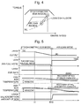
Fig. 6 is a time chart illustrating operations of the system when the SCR temperature exceeds an upper limit of the window when the target operating point moves as shown inFig. 4 ; -
Fig. 7 is a view illustrating another example of the movement of a target operating point at a time of deceleration; -
Fig. 8 is a time chart illustrating operations of the system when the SCR temperature remains within a window when the target operating point moves as shown inFig. 7 ; and -
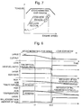
Fig. 9 is a time chart illustrating operations of the system when the SCR temperature exceeds an upper limit of the window when the target operating point moves as shown inFig. 7 . - Embodiments of the present disclosure are described hereunder with reference to the accompanying drawings. However, it is to be understood that even when the number, quantity, amount, range or other numerical attribute of an element is mentioned in the following description of the embodiments, the present disclosure is not limited to the mentioned numerical attribute unless it is expressly stated or theoretically defined. Further, structures or steps or the like described in conjunction with the following embodiments are not necessarily essential to embodiments of the present disclosure unless expressly stated or theoretically defined.
-
Fig. 1 is a view illustrating the configuration of a system according to an embodiment of the present disclosure. The system according to the present embodiment includes an internal combustion engine (hereunder, referred to as simply "engine") 2 that is mounted as a power apparatus in an automobile. The number of cylinders and cylinder arrangement of theengine 2 is not particularly limited. - The
engine 2 includes acylinder block 4 in which apiston 12 is disposed and a cylinder head 3. A space that is defined between the cylinder head 3 and thepiston 12 forms a combustion chamber 5. Theengine 2 is a spark-ignition type engine in which aspark plug 18 of an ignition device is installed in the cylinder head 3 so as to protrude into a top portion of the combustion chamber 5. - An
intake port 6 and anexhaust port 8 that are formed in the cylinder head 3 respectively open in the combustion chamber 5. A communicating state between the combustion chamber 5 and theintake port 6 is controlled by anintake valve 14 provided in the cylinder head 3. A communicating state between the combustion chamber 5 and theexhaust port 8 is controlled by an exhaust valve 16 provided in the cylinder head 3.Variable valve apparatuses intake valve 14 and the exhaust valve 16, respectively. - An in-
cylinder injection valve 22 that injects fuel directly into the combustion chamber 5, and aport injection valve 20 that injects fuel into theintake port 6 are installed in the cylinder head 3. The in-cylinder injection valve 22 is disposed below theintake port 6 so as to inject fuel towards the center of the combustion chamber 5 from an intake side of the combustion chamber 5. - An
intake manifold 10 is connected to theintake port 6 of the cylinder head 3. Theintake manifold 10 includes asurge tank 19. Anintake passage 30 that guides air that is taken in from anair cleaner 31 is connected to thesurge tank 19. An electronically controlledthrottle valve 40 is provided in theintake passage 30. Anexhaust manifold 11 is connected to theexhaust port 8 of the cylinder head 3. Anexhaust passage 32 that discharges exhaust gas to the outside is connected to theexhaust manifold 11. Anexhaust purification apparatus 60 is disposed in theexhaust passage 32. - The
engine 2 has aturbocharger 28. Acompressor 28a of theturbocharger 28 is provided upstream of thethrottle valve 40 in theintake passage 30. Anintercooler 36 that cools intake air that is compressed by thecompressor 28a is provided between thecompressor 28a and thethrottle valve 40. Aturbine 28b of theturbocharger 28 is provided upstream of theexhaust purification apparatus 60 in theexhaust passage 32. Abypass passage 44 that bypasses theturbine 28b is provided in theexhaust passage 32. An electronically controlledwaste gate valve 46 is installed in thebypass passage 44. - The
engine 2 includes anEGR apparatus 80 that recirculates a part of exhaust gas from theexhaust passage 32 to theintake passage 30. TheEGR apparatus 80 is an LPL-EGR apparatus (low-pressure EGR apparatus) that includes anEGR passage 82 that branches from theexhaust passage 32 at a position that is downstream relative to theexhaust purification apparatus 60, and connects to theintake passage 30 at a position that is upstream relative to thecompressor 28a. AnEGR cooler 84 is disposed on the upstream side of a flow of EGR gas in theEGR passage 82 relative to anEGR valve 86 is disposed on a downstream side of the flow of EGR gas. - The
exhaust purification apparatus 60 is constituted by a start catalyst (hereunder, referred to as "SC") 62 that is a three-way catalyst, a NOx storage-reduction catalyst (hereunder, referred to as "NSR") 64, and a selective catalytic reduction-type catalyst (hereunder, referred to as "SCR") 66. TheSC 62,NSR 64 andSCR 66 are disposed in that order from the upstream side in theexhaust passage 32. In other words, theSC 62 is upstream of theNSR 64, which is upstream of theSCR 66. - Under a lean atmosphere in which the oxygen concentration is high, the
SC 62 reduces NOx contained in exhaust gas to N2 while adsorbing oxygen contained in the exhaust gas. Under a rich atmosphere in which there is a low oxygen concentration, theSC 62 oxidizes HC and CO contained in exhaust gas while releasing oxygen to thereby change the HC and CO to H2O and CO2. - Under a lean atmosphere in which the oxygen concentration is high, the
NSR 64 stores NOx that is contained in exhaust gas, in the state of a nitrate. Subsequently, when HC, CO, H2 or the like that serves as a reducing agent is supplied by means of a rich spike, theNSR 64 releases the stored NOx to cause the reducing agent and the NOx to react and thereby reduce the NOx to NH3 and N2. - The
SCR 66 adsorbs NH3 that is generated in theNSR 64 as a result of the rich spike. TheSCR 66 causes the adsorbed NH3 and NOx contained in exhaust gas to react to reduce the NOx to N2. Note that, when a reducing agent is supplied by means of a rich spike, a reaction between NOx contained in exhaust gas and the reducing agent also occurs at theSC 62, and NH3 is generated from the NOx. Consequently, the NH3 that is adsorbed by theSCR 66 also includes NH3 generated at theSC 62, in addition to the NH3 generated at theNSR 64. - The system of the present embodiment includes sensors for obtaining information relating to the operating state of the
engine 2 at various places. Anair flow meter 34 for measuring a fresh air intake amount is arranged directly downstream of theair cleaner 31 in theintake passage 30. A limiting-current type air-fuel ratio sensor 70 is arranged directly upstream of theSC 62 in theexhaust passage 32. Atemperature sensor 74 is attached to theNSR 64 for measuring the temperature thereof (more specifically, a bed temperature). Atemperature sensor 76 is attached to theSCR 66 for measuring the temperature thereof (more specifically, a bed temperature). In addition, the system of the present embodiment also includes anaccelerator position sensor 52 for measuring a depression amount (accelerator opening degree) of an accelerator pedal, and acrank angle sensor 54 for measuring a crank angle of theengine 2. In addition to the aforementioned sensors, various sensors such as a combustion pressure sensor, an intake air pressure sensor, a supercharging pressure sensor, and a NOx sensor (none of which are illustrated in the drawings) are mounted in theengine 2 or the vehicle. - The various sensors and actuators described above are electrically connected to a
control device 50. Thecontrol device 50 is an ECU (electronic control unit) that has at least an input/output interface, a ROM, a RAM and a CPU. The input/output interface takes in sensor signals from various sensors mounted in theengine 2 and the vehicle, and also outputs actuating signals to actuators provided in theengine 2. The actuators include theport injection valve 20, the in-cylinder injection valve 22, the ignition apparatus including thespark plug 18, thethrottle valve 40, thewaste gate valve 46, theEGR valve 86, and thevariable valve apparatuses engine 2 and maps are stored in the ROM. The CPU reads out a control program from the ROM and executes the control program, and generates actuating signals based on sensor signals that are taken in. - Operation modes of the
engine 2 that are selected by thecontrol device 50 broadly include a stoichiometric mode that performs stoichiometric operation and a lean mode that performs lean operation. Stoichiometric operation is operation in which the in-cylinder air-fuel ratio is controlled to the theoretical air-fuel ratio. Lean operation is operation in which the in-cylinder air-fuel ratio is controlled to an air-fuel ratio that is leaner than the theoretical air-fuel ratio. In the present embodiment, the lean mode is further divided into a first lean mode that performs lean operation using only fresh air and without performing recirculation of EGR gas, and a second lean mode that performs recirculation of EGR gas. In the present embodiment, recirculation of EGR gas is also performed in the stoichiometric mode. Hereunder, the stoichiometric mode is referred to as "stoichiometric EGR mode", the first lean mode is referred to as "air lean mode", and the second lean mode is referred to as "lean EGR mode". -
Fig. 2 is a view illustrating a correlation between operation modes of theengine 2 that are selected by thecontrol device 50, and the torque and engine speed. A polygonal line that is shown by a thick solid line inFig. 2 is a boundary line between a region in which theengine 2 is capable of operating and a region in which theengine 2 is not capable of operating, and represents a maximum torque at each speed. Regions on a lower torque side than the boundary line are regions in which theengine 2 is capable of operating. - A polygonal line that is shown by a fine solid line in
Fig. 2 is a boundary line between a region in which stoichiometric operation is performed and a region in which lean operation is performed, and represents a maximum torque that can be realized by lean operation at each engine speed. A region on a high torque side of this boundary line is a region in which stoichiometric operation is performed among the regions in which theengine 2 is capable of operating, that is, a region in which the stoichiometric EGR mode is selected (hereunder, referred to as "stoichiometric EGR region"). On the other hand, a region on a low torque side of this boundary line is a region in which lean operation is performed (hereunder, also referred to as "lean region"), that is, a region in which the air lean mode or the lean EGR mode is selected. - A straight line that is shown by a broken line in
Fig. 2 is a boundary line between a region in which knocking is within an allowable range and a region in which knocking is not within an allowable range when lean operation is performed using only fresh air. A region on a high torque side of this boundary line is a region in which recirculation of EGR gas is performed among the regions in which lean operation is performed, that is, a region in which the lean EGR mode is selected (hereunder, also referred to as "lean EGR region"). On the other hand, a region on a low torque side of the boundary line is a region in which lean operation is performed using only fresh air, that is, a region in which the air lean mode is selected (hereunder, also referred to as "air lean region"). - In operation according to the stoichiometric EGR mode, a fuel injection amount is subjected to feedback control so that an output value of the air-
fuel ratio sensor 70 becomes a reference value corresponding to the theoretical air-fuel ratio. With regard to fuel injection in the stoichiometric EGR mode, one of fuel injection by combined use of theport injection valve 20 and the in-cylinder injection valve 22, and fuel injection using only the in-cylinder injection valve 22 is selected according to the operating point of theengine 2. For example, in a region in which scavenging occurs as a result of supercharging, stoichiometric operation is performed by means of fuel injection in an intake stroke or a compression stroke by the in-cylinder injection valve 22. In the stoichiometric EGR mode, in order to recirculate as large an amount of EGR gas as possible to suppress the occurrence of NOx as much as possible, the degree of opening of theEGR valve 86 that is the actuation amount of theEGR apparatus 80 is controlled to the maximum degree of opening so that the EGR rate becomes a maximum. - In operation according to the air lean mode, the in-cylinder air-fuel ratio is set to a very lean air-fuel ratio (for example, a value around 26) that is made lean to a degree that is close to a misfire limit. Further, in the air lean mode the EGR rate is set to zero and the
EGR valve 86 is fully closed. With regard to fuel injection in the air lean mode, one of the fuel injection by only theport injection valve 20, and fuel injection by combined use of theport injection valve 20 and the in-cylinder injection valve 22 is selected according to the operating point of theengine 2. The fuel injection by theport injection valve 20 is preferably asynchronous injection that is performed in a period in which theintake valve 14 is closed. However, the fuel injection by theport injection valve 20 may be synchronous injection in which a period in which theintake valve 14 is open and the fuel injection period overlap. The fuel injection by the in-cylinder injection valve 22 is an intake stroke injection that is performed in the intake stroke. Note that, in the air lean mode, the ignition timing is set to the MBT. - In the operation according to the lean EGR mode, to suppress knocking by introducing EGR gas into the cylinders, the opening degree of the
EGR valve 86 is controlled based on a previously set EGR rate. The set EGR rate in the lean EGR mode is set to as low a value as possible in a range that can effectively suppress knocking. Further, in the lean EGR mode, to adapt to a deterioration in the lean limit that is due to the introduction of EGR gas, the in-cylinder air-fuel ratio is set to an air-fuel ratio that is slightly richer than the set air-fuel ratio. With regard to fuel injection in the lean EGR mode, one of fuel injection by only theport injection valve 20, fuel injection by combined use of theport injection valve 20 and the in-cylinder injection valve 22, and fuel injection by only the in-cylinder injection valve 22 is selected in accordance with the operating point of theengine 2. In this connection, in the lean EGR mode, although the effect of suppressing knocking is high compared to the air lean mode, the fuel consumption performance declines in comparison to the air lean mode in which the cooling loss is less. Consequently, a region in which the lean EGR mode is selected is limited to a region in which knocking will exceed an allowable level if operation is performed according to the air lean mode. Note that, in the lean EGR mode the ignition timing is set to the retardation side relative to the MBT. - In operation according to the air lean mode and operation according to the lean EGR mode, a rich spike is executed in accordance with a predetermined execution rule. A rich spike that is executed in the present embodiment is a process that temporarily changes the in-cylinder air-fuel ratio to an air-fuel ratio that is richer than the theoretical air-fuel ratio by increasing the fuel injection amount per cycle. An increase in the fuel injection amount for the purpose of a rich spike is performed with respect to fuel that is injected from the in-
cylinder injection valve 22. By making the in-cylinder air-fuel ratio richer than the theoretical air-fuel ratio, the oxygen concentration contained in exhaust gas decreases and a large amount of reducing agents such as HC, CO and H2 are generated. As a result of the exhaust gas that includes a large amount of reducing agents being supplied to theNSR 64, NOx stored by theNSR 64 is released from theNSR 64 and is reduced to NH3 or N2 on theNSR 64. Note that, a rich spike is executed when the NOx concentration at the outlet of theNSR 64 that is measured by the NOx sensor (not illustrated) exceeds a predetermined threshold value, or when a stored amount of NOx that is calculated by estimation based on the engine speed, the intake air amount, and the air-fuel ratio exceeds a predetermined threshold value. - The
control device 50 calculates an output requested by the driver with respect to theengine 2 based on a depression amount of the accelerator pedal that is measured by theaccelerator position sensor 52. Based on the requested output, thecontrol device 50 determines a target operating point of theengine 2 that is defined by a target torque and a target speed, and selects the operation mode that is set in a region in which the target operating point is located. For example, inFig. 2 , when the target operating point crosses the boundary line that is shown by the fine solid line to move from the high torque side to the low torque side, thecontrol device 50 switches the operation mode from the stoichiometric EGR mode to the lean mode (air lean mode or lean EGR mode). Conversely, when the target operating point crosses the boundary line that is shown by the fine solid line to move from the low torque side to the high torque side, thecontrol device 50 switches the operation mode from the lean mode to the stoichiometric EGR mode. - However, in a case of switching the operation mode from the stoichiometric EGR mode to the lean mode, the
control device 50 always executes a rich spike before switching to the lean mode. This processing is performed whether the lean mode is the air lean mode or the lean EGR mode. Because the exhaust gas temperature during stoichiometric operation is a high temperature, oxidation of NH3 adsorbed on theSCR 66 occurs, and the NH3 adsorption amount of theSCR 66 decreases significantly. Therefore, by executing a rich spike to generate NH3 in theNSR 64, the NH3 adsorption amount of theSCR 66 that decreases during stoichiometric operation can be restored. Note that, a period (number of cycles) in which to execute a rich spike is previously determined. - In a case of switching the operation mode from the stoichiometric EGR mode to the lean mode, after execution of a rich spike, if a predetermined condition is established, the
control device 50 further executes transient control prior to switching to the lean mode. The predetermined condition is that the SCR temperature is greater than or equal to an upper limit temperature of a range. The SCR temperature that is used for the determination may be a value measured by thetemperature sensor 76 or may be an estimated value calculated based on the temperature and flow rate of the exhaust gas. The window is set to a temperature range in which theSCR 66 effectively operates, and an upper limit temperature thereof is set to 470°C at which an oxidation reaction of NH3 occurs or a temperature in the vicinity of 470°C. The timing for making a determination regarding the SCR temperature is immediately before switching from the stoichiometric EGR mode is performed or at exactly a time point at which such switching is performed. The former timing includes a time point at which switching from the stoichiometric EGR mode to the lean mode is determined in accordance with movement of the target operating point. The latter timing includes a time point at which a rich spike is completed. When the SCR temperature is greater than or equal to the upper limit temperature, because oxidation of NH3 that is generated by a rich spike occurs, the NH3 adsorption amount of theSCR 66 cannot be adequately restored. Therefore, control that is executed by thecontrol device 50 is transient control that is described next. - The transient control that the
control device 50 performs includes setting the EGR rate to a higher rate than the set EGR rate for the lean mode. By setting the EGR rate to at least a higher EGR rate than the set EGR rate for the lean mode, in comparison to a case of operating according to the settings in the lean mode, the oxygen concentration is relatively lowered and thus oxidation of NH3 can be suppressed. However, since the oxygen concentration contained in the exhaust gas becomes lower as the EGR rate increases, according to the transient control of the present embodiment, the degree of opening of theEGR valve 86 is controlled so that the EGR rate becomes the maximum EGR rate. By making the EGR rate the maximum rate, the oxygen concentration contained in the exhaust gas can be made as low as possible and oxidation of NH3 can be suppressed. - Further, the transient control that the
control device 50 performs includes, during a period in which the EGR rate is higher than the set EGR rate for the lean mode, controlling the in-cylinder air-fuel ratio to an air-fuel ratio that is richer than the set air-fuel ratio for the lean mode. The reason that the in-cylinder air-fuel ratio during transient control is made richer than the set air-fuel ratio for the lean mode is to act as a countermeasure to a deterioration in the lean limit that is caused by introduction of EGR gas. The higher the EGR rate, the more the lean limit deteriorates, and therefore the degree to which the in-cylinder air-fuel ratio is lean relative to the theoretical air-fuel ratio must be lowered. Because the EGR rate that is set in the transient control is higher than the set EGR rate for the lean EGR mode, the in-cylinder air-fuel ratio in the transient control is set to an air-fuel ratio that is richer than the set air-fuel ratio for the lean EGR mode. - The
control device 50 continues the above described transient control until the SCR temperature becomes lower than the upper limit temperature. The exhaust gas temperature decreases as a result of making the in-cylinder air-fuel ratio leaner than the theoretical air-fuel ratio, and eventually the SCR temperature falls to a temperature that is within the window. If the SCR temperature falls to a temperature within the window, it is no longer necessary to raise the EGR rate and lower the oxygen concentration. Since the transient control is also control that lowers the degree to which the in-cylinder air-fuel ratio is lean, the longer the transient control is continued, the greater the extent to which fuel consumption performance is lowered. Consequently, thecontrol device 50 ends the transient control once the SCR temperature falls within the window and transitions to the original setting for the air lean mode and the lean EGR mode depending on the region in which the target operating point is located. By this means, a decrease in the NOx purifying performance of the SCR due to oxidation of NH3 can be suppressed without wastefully lowering the fuel consumption performance. - The rich spike that the
control device 50 performs while the operation mode is being switched from the stoichiometric EGR mode to the lean mode corresponds to a function as first control means according to the present disclosure. Further, the transient control that thecontrol device 50 performs corresponds to a function as second control means according to the present disclosure. Note that, in a case of switching the operation mode from the lean mode to the stoichiometric EGR mode, special control such as the control described above is not performed. -
Fig. 3 is a flowchart illustrating the flow of engine control relating to switching of the operation mode. Thecontrol device 50 repeatedly executes the procedures shown in this flowchart at predetermined control periods that correspond to the clock speed of the ECU. - First, in step S2, a determination is performed as to whether or not the target operating point of the
engine 2 is within a lean region that is a region in which lean operation is performed. If the target operating point is not within the lean region, the processing in step S4 is selected. In step S4, the stoichiometric EGR mode is selected as the operation mode, and operation of theengine 2 is performed according to the stoichiometric EGR mode. - If the target operating point is within the lean region, next, the determination in step S6 is performed. In step S6, it is determined whether or not execution of a rich spike that is executed when switching to lean operation is already completed. When this is the first time that the target operating point enters the lean region with respect to the current switching operation, the result determined in step S6 is negative. Further, when execution of a rich spike is in progress, the result determined in step S6 is also negative. If the result determined in step S6 is negative, the processing in step S8 is selected. In step S8, if this is the first time that the target operating point enters the lean region with respect to the current switching operation, a rich spike is started, while when execution of a rich spike is in progress, execution of the rich spike is continued. The result determined in step S6 becomes affirmative when a previously determined execution period (number of cycles) elapses after the start of the rich spike.
- When execution of a rich spike is already completed, next a determination in step S10 is performed. In step S10, it is determined whether or not the SCR temperature is greater than or equal to the upper limit temperature. Note that the SCR temperature that is used for this determination may be an estimated value that is calculated based on the temperature and flow rate of exhaust gas. If the SCR temperature is greater than or equal to the upper limit temperature, the processing in step S12 is selected. In step S12, the transient control for suppressing oxidation of NH3 generated by a rich spike is executed, and not control for performing operation at the original set EGR rate and set air-fuel ratio for the lean mode. The transient control continues to be performed until the SCR temperature becomes lower than the upper limit temperature.
- When the SCR temperature is lower than the upper limit temperature, the processing in step S14 is selected. In step S14, one of the air lean mode and the lean EGR mode is selected depending on which of the lean regions the target operating point is in, and the
engine 2 is operated at the original set EGR rate and set air-fuel ratio for the air lean mode or the lean EGR mode. The air lean region in which the air lean mode is selected as the operation mode corresponds to, of the two lean regions, a region in which operation at the MBT is possible (MBT region). The lean EGR region in which the lean EGR mode is selected as the operation mode corresponds to, of the two lean regions, a region in which knocking occurs (knock region). - First, as shown in
Fig. 4 , operations of the system when, in a state in which the target operating point of theengine 2 is in the stoichiometric EGR region, the requested output decreases as a result of a deceleration request, and the target operating point moves from an operating point A within the stoichiometric EGR region to an operating point B within the air lean region. Note that, when a transmission gear ratio or a gear stage is fixed, the target operating point moves along a road load line (R/L) that is shown by an alternate long and short dashed line. The road load line is a curved line that links operating points at which the output of theengine 2 and the running load resistance balance out when the transmission gear ratio or the gear stage is fixed. -
Fig. 5 is a time chart illustrating operations of the system when the SCR temperature is within the window at a time of switching to the lean mode when the target operating point moved as shown inFig. 4 as a result of deceleration. The operations illustrated here are operations when, in the processing flow illustrated inFig. 3 , the processing in step S14 is selected without passing through the processing in step S12. In the time chart, changes in accordance with time in the engine output, the in-cylinder air-fuel ratio, the EGR rate, the NSR temperature, the SCR temperature and the NH3 adsorption amount of the SCR are illustrated. - According to this time chart, deceleration is started at a time t1, and a rich spike is executed at a time t2. This is because, at the time t2 or immediately prior thereto, the target operating point moves from the stoichiometric EGR region to the air lean region. The rich spike is executed for a predetermined period, and switching from the stoichiometric EGR mode to the air lean mode is performed at a time t3 at which the rich spike is completed.
- The SCR temperature already falls within the window prior to the time t2 at which the rich spike is executed. Therefore, the NH3 adsorption capacity of the
SCR 66 is already restored at the time t3. In this case, the transient control of the lean mode is not performed, and from the time t3 onwards theengine 2 is operated at the original set EGR rate and set air-fuel ratio for the air lean mode. In the air lean mode, the set EGR rate for is zero and the set air-fuel ratio is a very lean air-fuel ratio. Note that, in this time chart, a time that the NSR temperature falls within the window is a time that is after switching to the air lean mode at the time t3, and the NOx storage capacity of theNSR 64 is not restored for a while after switching. However, because the NH3 adsorption capacity of theSCR 66 is already restored, NOx that is not captured at theNSR 64 can be purified at theSCR 66. -
Fig. 6 is a time chart illustrating operations of the system when the SCR temperature when switching to the lean mode exceeds the window upper limit, when the target operating point moves as shown inFig. 4 as a result of deceleration. The operations illustrated inFig. 6 are, with respect to the processing flow illustrated inFig. 3 , operations when the processing in step S14 is selected after the processing in step S12 is repeated several times. In the time chart, changes in accordance with time in the engine output, the in-cylinder air-fuel ratio, the EGR rate, the NSR temperature, the SCR temperature and the NH3 adsorption amount of the SCR are illustrated. - In this time chart also, deceleration is started at a time t1, and a rich spike is executed at a time t2. However, because the SCR temperature at a time t3 at which the rich spike is completed exceeds the upper limit temperature of the window, switching to the lean mode is not immediately performed. That is, the transient control is performed, and not operation at the original set EGR rate and set air-fuel ratio for the air lean mode. In the time chart, changes in accordance with time in the EGR rate and air-fuel ratio when the transient control is executed are indicated by solid lines, and changes in accordance with time in the original EGR rate and air-fuel ratio of the air lean mode are indicated by broken lines.
- The transient control is continued until a time t4 at which the SCR temperature falls within the window. When the SCR temperature falls within the window, the NH3 adsorption capacity of the
SCR 66 is restored. Until that time, the EGR rate is set so as to be higher than the original set EGR rate for the air lean mode. More specifically, theEGR valve 86 is actuated so that the degree of opening thereof is such that the maximum EGR rate that is the set EGR rate for the stoichiometric EGR mode is maintained. Since oxidation of NH3 is suppressed under a high temperature environment by introduction of a large amount of EGR gas, the NH3 adsorption amount of theSCR 66 can be swiftly restored and, further, a decrease in the NOx purifying performance of theSCR 66 after switching to lean operation can be prevented. In the time chart, changes in accordance with time in the NH3 adsorption amount of theSCR 66 when the transient control is executed is indicated by a solid line, and changes in accordance with time in the NH3 adsorption amount when the transient control is not executed is indicated by a broken line. - Further, the in-cylinder air-fuel ratio during the transient control is controlled to an air-fuel ratio that, although leaner than the theoretical air-fuel ratio, is richer than the original set air-fuel ratio for the air lean mode. During a period in which the EGR rate is being raised, a destabilization in combustion due to an increase in the EGR rate can be prevented by making the in-cylinder air-fuel ratio richer than the original set air-fuel ratio for the air lean mode.
- Next, as shown in
Fig. 7 , operation of the system when, in a state in which the target operating point of theengine 2 is in the stoichiometric EGR region, the requested output decreases as a result of a deceleration request, and the target operating point moves from the operating point A within the stoichiometric EGR region to an operating point C within the lean EGR region. -
Fig. 8 is a time chart illustrating operation of the system when the SCR temperature is within the window at a time of switching to the lean mode when the target operating point moved as shown inFig. 7 as a result of deceleration. The operations illustrated here are operations when, in the processing flow illustrated inFig. 3 , the processing in step S14 is selected without passing through the processing in step S12. In the time chart, changes in accordance with time in the engine output, the in-cylinder air-fuel ratio, the EGR rate, the NSR temperature, the SCR temperature and the NH3 adsorption amount of the SCR are illustrated. - The operations of the system until a time t3 shown in the time chart in
Fig. 8 are the same as operations shown in the time chart inFig. 5 , and hence a description thereof is omitted. In this time chart, switching from the stoichiometric EGR mode to the lean EGR mode is performed at a time t3 at which a rich spike is completed. Since the SCR temperature at the time t3 is lower than the window upper limit, the transient control is not performed. From the time t3, operation is performed at the original set EGR rate and set air-fuel ratio for the lean EGR mode. The set EGR rate for the lean EGR mode is set to a lower value than the set EGR rate for the stoichiometric EGR mode. The set air-fuel ratio for the lean EGR mode is set to an air-fuel ratio that is richer than the set air-fuel ratio for the air lean mode. -
Fig. 9 is a time chart illustrating operation of the system when the SCR temperature when switching to the lean mode exceeds the window upper limit, when the target operating point moves as shown inFig. 7 as a result of deceleration. The operations illustrated inFig. 9 are, with respect to the processing flow illustrated inFig. 3 , operations when the processing in step S14 is selected after the processing in step S12 has been repeated several times. In the time chart, changes in accordance with time in the engine output, the in-cylinder air-fuel ratio, the EGR rate, the NSR temperature, the SCR temperature and the NH3 adsorption amount of the SCR are illustrated. - The operation of the system until a time t3 shown in the time chart in
Fig. 9 are the same as operations shown in the time chart inFig. 6 , and hence a description thereof is omitted. According to this time chart, because the SCR temperature at a time t3 at which a rich spike is completed exceeds the upper limit temperature of the window, after execution of the rich spike, the transient control is performed, and not operation at the original set EGR rate and set air-fuel ratio for the lean EGR mode. In the time chart, changes in accordance with time in the EGR rate and air-fuel ratio when the transient control is executed are indicated by solid lines, and changes in accordance with time in the original EGR rate and air-fuel ratio for the lean EGR mode are indicated by broken lines. - The transient control is continued until a time t4 at which the SCR temperature falls within the window. During the period until the time t4, the EGR rate is maintained at the maximum EGR rate that is the set EGR rate for the stoichiometric EGR mode. By this means, an amount of EGR gas is introduced that is larger than the amount of EGR gas that is introduced in the lean EGR mode, and hence oxidation of NH3 under a high temperature environment is suppressed. In the time chart, changes in accordance with time in the NH3 adsorption amount of the
SCR 66 when the transient control is executed are illustrated by a solid line, and changes in accordance with time in the NH3 adsorption amount when the transient control is not executed are illustrated by a broken line. By executing the transient control, the NH3 adsorption amount of theSCR 66 can be swiftly recovered, and further, a decrease in the NOx purifying performance of theSCR 66 after switching to lean operation can be prevented. - Further, the in-cylinder air-fuel ratio during the transient control is controlled to an air-fuel ratio that, although leaner than the theoretical air-fuel ratio, is richer than the original set air-fuel ratio for the lean EGR mode. During a period in which the EGR rate is being raised, a destabilization in combustion due to an increase in the EGR rate can be prevented by making the in-cylinder air-fuel ratio richer than the original set air-fuel ratio for the lean EGR mode.
- Although in the above described embodiment, in the stoichiometric EGR mode, the degree of opening of the EGR valve is set to the maximum degree to control the EGR rate to the maximum rate, a configuration may also be adopted in which the set EGR rate for the stoichiometric EGR mode is set lower than the maximum EGR rate. Further, it is not necessary to set the EGR rate for the transient control to the same rate as the set EGR rate for the stoichiometric EGR mode, and it is sufficient to set the EGR rate for the transient control to a rate that is higher than the set EGR rate for the lean mode.
- A rich spike is not limited to the rich spike described in the above embodiment, as long as the rich spike is a method that can supply excessive fuel relative to the theoretical air-fuel ratio. For example, by injecting fuel in an expansion stroke or an exhaust stroke by means of the in-
cylinder injection valve 22 or the like, post-injection of fuel that does not contribute to torque may be performed separately to fuel injection that contributes to torque. Further, a method can also be adopted in which fuel injected into theintake port 6 from theport injection valve 20 during a period in which theintake valve 14 is closed is blown through to theexhaust port 8 utilizing scavenging. Note that, apart from the position shown inFig. 1 , the in-cylinder injection valve 22 can also be disposed side by side with thespark plug 18 at the top portion of the combustion chamber 5. - Although the engine according to the above described embodiments is a turbocharged engine, the present disclosure can also be applied to a naturally aspirated engine that does not include a turbocharger.
-
- 2 Engine
- 5 Combustion chamber
- 6 Intake port
- 20 Port injection valve
- 22 In-cylinder injection valve
- 30 Intake passage
- 32 Exhaust passage
- 50 Control device
- 60 Exhaust purification apparatus
- 62 Start catalyst (SC)
- 64 NOx storage-reduction catalyst (NSR)
- 66 Selective catalytic reduction-type catalyst (SCR)
- 80 EGR apparatus
- 82 EGR passage
- 84 EGR cooler
- 86 EGR valve
Claims (3)
- A control device (50) for an internal combustion engine (2) that comprises a selective catalytic reduction-type catalyst (66) disposed in an exhaust passage (32), a NOx storage-reduction catalyst (64) disposed upstream relative to the selective catalytic reduction-type catalyst (66) in the exhaust passage (32), and an EGR apparatus (80) that recirculates EGR gas from the exhaust passage (32) to an intake passage (30), wherein:operation modes of the internal combustion engine (2) that are selected by the control device (50) include:a stoichiometric mode that controls an in-cylinder air-fuel ratio to a theoretical air-fuel ratio, anda lean mode that controls the in-cylinder air-fuel ratio to an air-fuel ratio that is leaner than the theoretical air-fuel ratio;the control device (50) comprising:first control means configured to, during a period in which the operation mode is switched from the stoichiometric mode to the lean mode, execute a rich spike that supplies excessive fuel relative to the theoretical air-fuel ratio, andsecond control means configured to, when a temperature of the selective catalytic reduction-type catalyst (66) at a time of switching from the stoichiometric mode is greater than or equal to an upper limit temperature, after execution of the rich spike, switch to the lean mode after executing transient control that makes an EGR rate that is a proportion of EGR gas included in intake gas, higher than an EGR rate in the lean mode, and makes the in-cylinder air-fuel ratio leaner than the theoretical air-fuel ratio and richer than an air-fuel ratio in the lean mode.
- The control device (50) for an internal combustion engine (2) according to claim 1, wherein the second control means is configured to further execute the transient control until the temperature of the selective catalytic reduction-type catalyst (66) becomes lower than the upper limit temperature.
- The control device (50) for an internal combustion engine (2) according to claim 1 or 2, wherein, in the transient control, the second control means is configured to further actuate the EGR apparatus (80) so that the EGR rate becomes a maximum.
Applications Claiming Priority (1)
| Application Number | Priority Date | Filing Date | Title |
|---|---|---|---|
| JP2015116857A JP6350397B2 (en) | 2015-06-09 | 2015-06-09 | Control device for internal combustion engine |
Publications (2)
| Publication Number | Publication Date |
|---|---|
| EP3103993A1 true EP3103993A1 (en) | 2016-12-14 |
| EP3103993B1 EP3103993B1 (en) | 2019-05-01 |
Family
ID=56087176
Family Applications (1)
| Application Number | Title | Priority Date | Filing Date |
|---|---|---|---|
| EP16171856.4A Active EP3103993B1 (en) | 2015-06-09 | 2016-05-30 | Control device for internal combustion engine |
Country Status (4)
| Country | Link |
|---|---|
| US (1) | US10174695B2 (en) |
| EP (1) | EP3103993B1 (en) |
| JP (1) | JP6350397B2 (en) |
| CN (1) | CN106246368B (en) |
Cited By (2)
| Publication number | Priority date | Publication date | Assignee | Title |
|---|---|---|---|---|
| CN106948908A (en) * | 2017-03-24 | 2017-07-14 | 潍柴动力股份有限公司 | A kind of vanadium base SCR active regeneration systems control method and control device |
| CN108846132A (en) * | 2018-07-03 | 2018-11-20 | 集美大学 | Marine diesel SCR electric-control system MAP chart querying method based on recipe file |
Families Citing this family (19)
| Publication number | Priority date | Publication date | Assignee | Title |
|---|---|---|---|---|
| JP6287802B2 (en) * | 2014-12-12 | 2018-03-07 | トヨタ自動車株式会社 | Control device for internal combustion engine |
| JP6213523B2 (en) * | 2015-06-09 | 2017-10-18 | トヨタ自動車株式会社 | Control device for internal combustion engine |
| US9739199B2 (en) * | 2015-10-30 | 2017-08-22 | General Electric Company | Intercooled gas turbine optimization |
| US11199162B2 (en) | 2016-01-19 | 2021-12-14 | Eaton Intelligent Power Limited | In-cylinder EGR and VVA for aftertreatment temperature control |
| US10801430B2 (en) * | 2016-01-19 | 2020-10-13 | Eaton Intelligent Power Limited | In-cylinder EGR for air fuel ratio control |
| KR101886090B1 (en) * | 2016-07-26 | 2018-08-07 | 현대자동차 주식회사 | Engine system |
| US10393043B2 (en) | 2017-07-06 | 2019-08-27 | GM Global Technology Operations LLC | System and method for adapting combustion to mitigate exhaust overtemperature |
| CN107420210B (en) * | 2017-07-18 | 2019-09-03 | 中国第一汽车股份有限公司 | A kind of directly jetting gasoline engine gaseous mixture self-adaptation control method |
| WO2019125442A1 (en) | 2017-12-20 | 2019-06-27 | Cummins Inc. | Techniques for improving fuel economy in dedicated egr engines |
| JP6729543B2 (en) * | 2017-12-27 | 2020-07-22 | トヨタ自動車株式会社 | Exhaust gas purification device for internal combustion engine |
| JP6973195B2 (en) * | 2018-03-08 | 2021-11-24 | いすゞ自動車株式会社 | Exhaust purification device, vehicle and exhaust purification control device |
| JP7131171B2 (en) * | 2018-07-26 | 2022-09-06 | マツダ株式会社 | Compression ignition engine controller |
| JP7110837B2 (en) * | 2018-09-04 | 2022-08-02 | トヨタ自動車株式会社 | Exhaust purification system for internal combustion engine |
| US10815920B2 (en) * | 2018-10-19 | 2020-10-27 | Deere & Company | Engine system and method with hydrocarbon injection and EGR |
| JP2021102930A (en) * | 2019-12-25 | 2021-07-15 | 株式会社デンソー | Engine system |
| FR3120253A1 (en) * | 2021-03-01 | 2022-09-02 | Renault S.A.S | Method and system for controlling a spark-ignition internal combustion engine in the kick-off phase. |
| JP2022136514A (en) * | 2021-03-08 | 2022-09-21 | マツダ株式会社 | engine |
| CN113565619B (en) * | 2021-06-29 | 2022-11-01 | 东风汽车集团股份有限公司 | Engine and air inlet and exhaust system thereof |
| GB2612131B (en) * | 2021-10-25 | 2024-01-03 | Jaguar Land Rover Ltd | Methods and apparatus for mitigating fuel in oil |
Citations (6)
| Publication number | Priority date | Publication date | Assignee | Title |
|---|---|---|---|---|
| JPH06200751A (en) * | 1993-01-07 | 1994-07-19 | Mazda Motor Corp | Exhaust emission control device for engine |
| EP0957254A2 (en) * | 1998-05-15 | 1999-11-17 | Toyota Jidosha Kabushiki Kaisha | Exhaust gas purifying apparatus for internal combustion engine |
| WO2012152833A1 (en) * | 2011-05-10 | 2012-11-15 | Umicore Ag & Co. Kg | Method for regenerating nox storage catalytic converters of diesel engines with low-pressure egr |
| JP2014001682A (en) | 2012-06-19 | 2014-01-09 | Toyota Motor Corp | Exhaust gas purifier of internal combustion engine |
| US20140356237A1 (en) * | 2012-02-07 | 2014-12-04 | Toyota Jidosha Kabushiki Kaisha | Exhaust gas purification apparatus for internal combustion engine |
| WO2015001647A1 (en) * | 2013-07-04 | 2015-01-08 | トヨタ自動車株式会社 | Exhaust gas cleaning system for internal combustion engine |
Family Cites Families (12)
| Publication number | Priority date | Publication date | Assignee | Title |
|---|---|---|---|---|
| JPH1047042A (en) * | 1996-08-02 | 1998-02-17 | Mitsubishi Motors Corp | Emission control system |
| JP4196471B2 (en) * | 1999-03-09 | 2008-12-17 | マツダ株式会社 | Engine control device |
| US7810315B2 (en) * | 2007-02-20 | 2010-10-12 | Eaton Corporation | LNT regeneration strategy to reduce NOx spike |
| EP2413205B1 (en) * | 2009-03-27 | 2014-04-09 | Honda Motor Co., Ltd. | Controller for plant |
| JP5282828B2 (en) | 2009-11-18 | 2013-09-04 | トヨタ自動車株式会社 | Exhaust gas purification system for internal combustion engine |
| JP5686036B2 (en) * | 2011-05-13 | 2015-03-18 | トヨタ自動車株式会社 | Control device for internal combustion engine |
| JP5866833B2 (en) * | 2011-07-11 | 2016-02-24 | いすゞ自動車株式会社 | Internal combustion engine and EGR method for internal combustion engine |
| US8931265B2 (en) | 2012-05-10 | 2015-01-13 | GM Global Technology Operations LLC | Closed loop temperature control in the SCR warm up mode to reduce emission variation |
| WO2014024274A1 (en) * | 2012-08-08 | 2014-02-13 | トヨタ自動車株式会社 | Exhaust purification device for internal combustion engine |
| JP2014101836A (en) | 2012-11-21 | 2014-06-05 | Toyota Motor Corp | Exhaust emission control system of internal combustion engine |
| US9255537B2 (en) | 2013-03-15 | 2016-02-09 | GM Global Technology Operations LLC | Rejuvenation control of palladium-only diesel oxidation catalyst |
| JP2016223294A (en) * | 2015-05-27 | 2016-12-28 | いすゞ自動車株式会社 | Exhaust emission control system |
-
2015
- 2015-06-09 JP JP2015116857A patent/JP6350397B2/en not_active Expired - Fee Related
-
2016
- 2016-05-30 EP EP16171856.4A patent/EP3103993B1/en active Active
- 2016-05-31 CN CN201610374276.5A patent/CN106246368B/en active Active
- 2016-06-07 US US15/175,493 patent/US10174695B2/en active Active
Patent Citations (6)
| Publication number | Priority date | Publication date | Assignee | Title |
|---|---|---|---|---|
| JPH06200751A (en) * | 1993-01-07 | 1994-07-19 | Mazda Motor Corp | Exhaust emission control device for engine |
| EP0957254A2 (en) * | 1998-05-15 | 1999-11-17 | Toyota Jidosha Kabushiki Kaisha | Exhaust gas purifying apparatus for internal combustion engine |
| WO2012152833A1 (en) * | 2011-05-10 | 2012-11-15 | Umicore Ag & Co. Kg | Method for regenerating nox storage catalytic converters of diesel engines with low-pressure egr |
| US20140356237A1 (en) * | 2012-02-07 | 2014-12-04 | Toyota Jidosha Kabushiki Kaisha | Exhaust gas purification apparatus for internal combustion engine |
| JP2014001682A (en) | 2012-06-19 | 2014-01-09 | Toyota Motor Corp | Exhaust gas purifier of internal combustion engine |
| WO2015001647A1 (en) * | 2013-07-04 | 2015-01-08 | トヨタ自動車株式会社 | Exhaust gas cleaning system for internal combustion engine |
Cited By (4)
| Publication number | Priority date | Publication date | Assignee | Title |
|---|---|---|---|---|
| CN106948908A (en) * | 2017-03-24 | 2017-07-14 | 潍柴动力股份有限公司 | A kind of vanadium base SCR active regeneration systems control method and control device |
| CN106948908B (en) * | 2017-03-24 | 2019-05-28 | 潍柴动力股份有限公司 | A kind of vanadium base SCR active regeneration system control method and control device |
| CN108846132A (en) * | 2018-07-03 | 2018-11-20 | 集美大学 | Marine diesel SCR electric-control system MAP chart querying method based on recipe file |
| CN108846132B (en) * | 2018-07-03 | 2021-03-26 | 集美大学 | Marine diesel engine SCR electric control system MAP graph query method based on formula file |
Also Published As
| Publication number | Publication date |
|---|---|
| US20160363070A1 (en) | 2016-12-15 |
| CN106246368B (en) | 2019-04-05 |
| JP6350397B2 (en) | 2018-07-04 |
| JP2017002792A (en) | 2017-01-05 |
| EP3103993B1 (en) | 2019-05-01 |
| US10174695B2 (en) | 2019-01-08 |
| CN106246368A (en) | 2016-12-21 |
Similar Documents
| Publication | Publication Date | Title |
|---|---|---|
| EP3103993B1 (en) | Control device for internal combustion engine | |
| JP5187123B2 (en) | Control device for internal combustion engine | |
| US8661791B2 (en) | Systems and methods for controlling regeneration of nitrogen oxide adsorbers | |
| US8302382B2 (en) | Exhaust gas purification system for internal combustion engine and control method for same | |
| JP4309908B2 (en) | Exhaust gas purification device for internal combustion engine | |
| US10001074B2 (en) | Control apparatus for internal combustion engine | |
| JP2009191659A (en) | Control device of internal combustion engine | |
| EP2843216B1 (en) | Internal combustion engine control device | |
| US7475536B2 (en) | Exhaust gas purifying apparatus for internal combustion engine | |
| JP5920368B2 (en) | Control device for internal combustion engine | |
| JP2007239493A (en) | Internal combustion engine with supercharger | |
| US7886526B2 (en) | Fuel control of an internal-combustion engine | |
| JP2001234772A (en) | Exhaust emission control device for internal combustion engine | |
| JPH10184418A (en) | Exhaust purifying device for lean combustion engine | |
| JP6230002B1 (en) | Engine exhaust purification system | |
| JP6699272B2 (en) | Engine and control method thereof | |
| JP6268682B2 (en) | Engine exhaust purification system | |
| JP5379733B2 (en) | Engine exhaust purification system | |
| JP4175952B2 (en) | Combustion control device for internal combustion engine | |
| JP6230003B1 (en) | Engine exhaust purification system | |
| JP6230004B1 (en) | Engine exhaust purification system | |
| JP4502899B2 (en) | Exhaust gas purification device | |
| JP6287175B2 (en) | Engine control device | |
| JP2006070732A (en) | Exhaust emission control system of internal combustion engine | |
| JP2015025410A (en) | Control device of engine |
Legal Events
| Date | Code | Title | Description |
|---|---|---|---|
| PUAI | Public reference made under article 153(3) epc to a published international application that has entered the european phase |
Free format text: ORIGINAL CODE: 0009012 |
|
| STAA | Information on the status of an ep patent application or granted ep patent |
Free format text: STATUS: REQUEST FOR EXAMINATION WAS MADE |
|
| 17P | Request for examination filed |
Effective date: 20160530 |
|
| AK | Designated contracting states |
Kind code of ref document: A1 Designated state(s): AL AT BE BG CH CY CZ DE DK EE ES FI FR GB GR HR HU IE IS IT LI LT LU LV MC MK MT NL NO PL PT RO RS SE SI SK SM TR |
|
| AX | Request for extension of the european patent |
Extension state: BA ME |
|
| REG | Reference to a national code |
Ref country code: DE Ref legal event code: R079 Ref document number: 602016013051 Country of ref document: DE Free format text: PREVIOUS MAIN CLASS: F02D0041140000 Ipc: F02D0041000000 |
|
| RIC1 | Information provided on ipc code assigned before grant |
Ipc: F02D 41/14 20060101ALI20181113BHEP Ipc: F02D 41/02 20060101ALN20181113BHEP Ipc: F02M 26/06 20160101ALI20181113BHEP Ipc: F02D 41/00 20060101AFI20181113BHEP Ipc: F02D 13/02 20060101ALN20181113BHEP Ipc: F01N 3/08 20060101ALN20181113BHEP Ipc: F01N 3/20 20060101ALI20181113BHEP Ipc: F02D 41/30 20060101ALI20181113BHEP Ipc: F02M 26/15 20160101ALI20181113BHEP |
|
| GRAP | Despatch of communication of intention to grant a patent |
Free format text: ORIGINAL CODE: EPIDOSNIGR1 |
|
| STAA | Information on the status of an ep patent application or granted ep patent |
Free format text: STATUS: GRANT OF PATENT IS INTENDED |
|
| INTG | Intention to grant announced |
Effective date: 20190103 |
|
| GRAS | Grant fee paid |
Free format text: ORIGINAL CODE: EPIDOSNIGR3 |
|
| GRAA | (expected) grant |
Free format text: ORIGINAL CODE: 0009210 |
|
| STAA | Information on the status of an ep patent application or granted ep patent |
Free format text: STATUS: THE PATENT HAS BEEN GRANTED |
|
| AK | Designated contracting states |
Kind code of ref document: B1 Designated state(s): AL AT BE BG CH CY CZ DE DK EE ES FI FR GB GR HR HU IE IS IT LI LT LU LV MC MK MT NL NO PL PT RO RS SE SI SK SM TR |
|
| REG | Reference to a national code |
Ref country code: GB Ref legal event code: FG4D |
|
| REG | Reference to a national code |
Ref country code: CH Ref legal event code: EP Ref country code: AT Ref legal event code: REF Ref document number: 1127232 Country of ref document: AT Kind code of ref document: T Effective date: 20190515 |
|
| REG | Reference to a national code |
Ref country code: DE Ref legal event code: R096 Ref document number: 602016013051 Country of ref document: DE |
|
| REG | Reference to a national code |
Ref country code: IE Ref legal event code: FG4D |
|
| REG | Reference to a national code |
Ref country code: DE Ref legal event code: R084 Ref document number: 602016013051 Country of ref document: DE |
|
| REG | Reference to a national code |
Ref country code: GB Ref legal event code: 746 Effective date: 20190716 |
|
| REG | Reference to a national code |
Ref country code: NL Ref legal event code: MP Effective date: 20190501 |
|
| REG | Reference to a national code |
Ref country code: LT Ref legal event code: MG4D |
|
| PG25 | Lapsed in a contracting state [announced via postgrant information from national office to epo] |
Ref country code: FI Free format text: LAPSE BECAUSE OF FAILURE TO SUBMIT A TRANSLATION OF THE DESCRIPTION OR TO PAY THE FEE WITHIN THE PRESCRIBED TIME-LIMIT Effective date: 20190501 Ref country code: NO Free format text: LAPSE BECAUSE OF FAILURE TO SUBMIT A TRANSLATION OF THE DESCRIPTION OR TO PAY THE FEE WITHIN THE PRESCRIBED TIME-LIMIT Effective date: 20190801 Ref country code: NL Free format text: LAPSE BECAUSE OF FAILURE TO SUBMIT A TRANSLATION OF THE DESCRIPTION OR TO PAY THE FEE WITHIN THE PRESCRIBED TIME-LIMIT Effective date: 20190501 Ref country code: AL Free format text: LAPSE BECAUSE OF FAILURE TO SUBMIT A TRANSLATION OF THE DESCRIPTION OR TO PAY THE FEE WITHIN THE PRESCRIBED TIME-LIMIT Effective date: 20190501 Ref country code: SE Free format text: LAPSE BECAUSE OF FAILURE TO SUBMIT A TRANSLATION OF THE DESCRIPTION OR TO PAY THE FEE WITHIN THE PRESCRIBED TIME-LIMIT Effective date: 20190501 Ref country code: PT Free format text: LAPSE BECAUSE OF FAILURE TO SUBMIT A TRANSLATION OF THE DESCRIPTION OR TO PAY THE FEE WITHIN THE PRESCRIBED TIME-LIMIT Effective date: 20190901 Ref country code: LT Free format text: LAPSE BECAUSE OF FAILURE TO SUBMIT A TRANSLATION OF THE DESCRIPTION OR TO PAY THE FEE WITHIN THE PRESCRIBED TIME-LIMIT Effective date: 20190501 Ref country code: HR Free format text: LAPSE BECAUSE OF FAILURE TO SUBMIT A TRANSLATION OF THE DESCRIPTION OR TO PAY THE FEE WITHIN THE PRESCRIBED TIME-LIMIT Effective date: 20190501 Ref country code: ES Free format text: LAPSE BECAUSE OF FAILURE TO SUBMIT A TRANSLATION OF THE DESCRIPTION OR TO PAY THE FEE WITHIN THE PRESCRIBED TIME-LIMIT Effective date: 20190501 |
|
| PG25 | Lapsed in a contracting state [announced via postgrant information from national office to epo] |
Ref country code: RS Free format text: LAPSE BECAUSE OF FAILURE TO SUBMIT A TRANSLATION OF THE DESCRIPTION OR TO PAY THE FEE WITHIN THE PRESCRIBED TIME-LIMIT Effective date: 20190501 Ref country code: BG Free format text: LAPSE BECAUSE OF FAILURE TO SUBMIT A TRANSLATION OF THE DESCRIPTION OR TO PAY THE FEE WITHIN THE PRESCRIBED TIME-LIMIT Effective date: 20190801 Ref country code: GR Free format text: LAPSE BECAUSE OF FAILURE TO SUBMIT A TRANSLATION OF THE DESCRIPTION OR TO PAY THE FEE WITHIN THE PRESCRIBED TIME-LIMIT Effective date: 20190802 Ref country code: LV Free format text: LAPSE BECAUSE OF FAILURE TO SUBMIT A TRANSLATION OF THE DESCRIPTION OR TO PAY THE FEE WITHIN THE PRESCRIBED TIME-LIMIT Effective date: 20190501 |
|
| REG | Reference to a national code |
Ref country code: AT Ref legal event code: MK05 Ref document number: 1127232 Country of ref document: AT Kind code of ref document: T Effective date: 20190501 |
|
| REG | Reference to a national code |
Ref country code: CH Ref legal event code: PL |
|
| PG25 | Lapsed in a contracting state [announced via postgrant information from national office to epo] |
Ref country code: IS Free format text: LAPSE BECAUSE OF FAILURE TO SUBMIT A TRANSLATION OF THE DESCRIPTION OR TO PAY THE FEE WITHIN THE PRESCRIBED TIME-LIMIT Effective date: 20190901 |
|
| PG25 | Lapsed in a contracting state [announced via postgrant information from national office to epo] |
Ref country code: RO Free format text: LAPSE BECAUSE OF FAILURE TO SUBMIT A TRANSLATION OF THE DESCRIPTION OR TO PAY THE FEE WITHIN THE PRESCRIBED TIME-LIMIT Effective date: 20190501 Ref country code: SK Free format text: LAPSE BECAUSE OF FAILURE TO SUBMIT A TRANSLATION OF THE DESCRIPTION OR TO PAY THE FEE WITHIN THE PRESCRIBED TIME-LIMIT Effective date: 20190501 Ref country code: CZ Free format text: LAPSE BECAUSE OF FAILURE TO SUBMIT A TRANSLATION OF THE DESCRIPTION OR TO PAY THE FEE WITHIN THE PRESCRIBED TIME-LIMIT Effective date: 20190501 Ref country code: EE Free format text: LAPSE BECAUSE OF FAILURE TO SUBMIT A TRANSLATION OF THE DESCRIPTION OR TO PAY THE FEE WITHIN THE PRESCRIBED TIME-LIMIT Effective date: 20190501 Ref country code: AT Free format text: LAPSE BECAUSE OF FAILURE TO SUBMIT A TRANSLATION OF THE DESCRIPTION OR TO PAY THE FEE WITHIN THE PRESCRIBED TIME-LIMIT Effective date: 20190501 Ref country code: DK Free format text: LAPSE BECAUSE OF FAILURE TO SUBMIT A TRANSLATION OF THE DESCRIPTION OR TO PAY THE FEE WITHIN THE PRESCRIBED TIME-LIMIT Effective date: 20190501 Ref country code: CH Free format text: LAPSE BECAUSE OF NON-PAYMENT OF DUE FEES Effective date: 20190531 Ref country code: MC Free format text: LAPSE BECAUSE OF FAILURE TO SUBMIT A TRANSLATION OF THE DESCRIPTION OR TO PAY THE FEE WITHIN THE PRESCRIBED TIME-LIMIT Effective date: 20190501 Ref country code: LI Free format text: LAPSE BECAUSE OF NON-PAYMENT OF DUE FEES Effective date: 20190531 |
|
| REG | Reference to a national code |
Ref country code: DE Ref legal event code: R097 Ref document number: 602016013051 Country of ref document: DE |
|
| REG | Reference to a national code |
Ref country code: BE Ref legal event code: MM Effective date: 20190531 |
|
| PG25 | Lapsed in a contracting state [announced via postgrant information from national office to epo] |
Ref country code: IT Free format text: LAPSE BECAUSE OF FAILURE TO SUBMIT A TRANSLATION OF THE DESCRIPTION OR TO PAY THE FEE WITHIN THE PRESCRIBED TIME-LIMIT Effective date: 20190501 Ref country code: LU Free format text: LAPSE BECAUSE OF NON-PAYMENT OF DUE FEES Effective date: 20190530 Ref country code: SM Free format text: LAPSE BECAUSE OF FAILURE TO SUBMIT A TRANSLATION OF THE DESCRIPTION OR TO PAY THE FEE WITHIN THE PRESCRIBED TIME-LIMIT Effective date: 20190501 |
|
| PLBE | No opposition filed within time limit |
Free format text: ORIGINAL CODE: 0009261 |
|
| STAA | Information on the status of an ep patent application or granted ep patent |
Free format text: STATUS: NO OPPOSITION FILED WITHIN TIME LIMIT |
|
| PG25 | Lapsed in a contracting state [announced via postgrant information from national office to epo] |
Ref country code: TR Free format text: LAPSE BECAUSE OF FAILURE TO SUBMIT A TRANSLATION OF THE DESCRIPTION OR TO PAY THE FEE WITHIN THE PRESCRIBED TIME-LIMIT Effective date: 20190501 |
|
| 26N | No opposition filed |
Effective date: 20200204 |
|
| PG25 | Lapsed in a contracting state [announced via postgrant information from national office to epo] |
Ref country code: PL Free format text: LAPSE BECAUSE OF FAILURE TO SUBMIT A TRANSLATION OF THE DESCRIPTION OR TO PAY THE FEE WITHIN THE PRESCRIBED TIME-LIMIT Effective date: 20190501 Ref country code: IE Free format text: LAPSE BECAUSE OF NON-PAYMENT OF DUE FEES Effective date: 20190530 |
|
| PG25 | Lapsed in a contracting state [announced via postgrant information from national office to epo] |
Ref country code: BE Free format text: LAPSE BECAUSE OF NON-PAYMENT OF DUE FEES Effective date: 20190531 Ref country code: SI Free format text: LAPSE BECAUSE OF FAILURE TO SUBMIT A TRANSLATION OF THE DESCRIPTION OR TO PAY THE FEE WITHIN THE PRESCRIBED TIME-LIMIT Effective date: 20190501 |
|
| PG25 | Lapsed in a contracting state [announced via postgrant information from national office to epo] |
Ref country code: CY Free format text: LAPSE BECAUSE OF FAILURE TO SUBMIT A TRANSLATION OF THE DESCRIPTION OR TO PAY THE FEE WITHIN THE PRESCRIBED TIME-LIMIT Effective date: 20190501 |
|
| PG25 | Lapsed in a contracting state [announced via postgrant information from national office to epo] |
Ref country code: HU Free format text: LAPSE BECAUSE OF FAILURE TO SUBMIT A TRANSLATION OF THE DESCRIPTION OR TO PAY THE FEE WITHIN THE PRESCRIBED TIME-LIMIT; INVALID AB INITIO Effective date: 20160530 Ref country code: MT Free format text: LAPSE BECAUSE OF FAILURE TO SUBMIT A TRANSLATION OF THE DESCRIPTION OR TO PAY THE FEE WITHIN THE PRESCRIBED TIME-LIMIT Effective date: 20190501 |
|
| PG25 | Lapsed in a contracting state [announced via postgrant information from national office to epo] |
Ref country code: MK Free format text: LAPSE BECAUSE OF FAILURE TO SUBMIT A TRANSLATION OF THE DESCRIPTION OR TO PAY THE FEE WITHIN THE PRESCRIBED TIME-LIMIT Effective date: 20190501 |
|
| PGFP | Annual fee paid to national office [announced via postgrant information from national office to epo] |
Ref country code: GB Payment date: 20220407 Year of fee payment: 7 Ref country code: FR Payment date: 20220408 Year of fee payment: 7 Ref country code: DE Payment date: 20220406 Year of fee payment: 7 |
|
| P01 | Opt-out of the competence of the unified patent court (upc) registered |
Effective date: 20230427 |
|
| REG | Reference to a national code |
Ref country code: DE Ref legal event code: R119 Ref document number: 602016013051 Country of ref document: DE |
|
| GBPC | Gb: european patent ceased through non-payment of renewal fee |
Effective date: 20230530 |