EP3103771B1 - Method and apparatus for controlling concentration of free chlorine - Google Patents
Method and apparatus for controlling concentration of free chlorine Download PDFInfo
- Publication number
- EP3103771B1 EP3103771B1 EP15745808.4A EP15745808A EP3103771B1 EP 3103771 B1 EP3103771 B1 EP 3103771B1 EP 15745808 A EP15745808 A EP 15745808A EP 3103771 B1 EP3103771 B1 EP 3103771B1
- Authority
- EP
- European Patent Office
- Prior art keywords
- anode
- cathode
- concentration
- electrode
- aqueous solution
- Prior art date
- Legal status (The legal status is an assumption and is not a legal conclusion. Google has not performed a legal analysis and makes no representation as to the accuracy of the status listed.)
- Active
Links
- 238000000034 method Methods 0.000 title claims description 396
- ZAMOUSCENKQFHK-UHFFFAOYSA-N Chlorine atom Chemical compound [Cl] ZAMOUSCENKQFHK-UHFFFAOYSA-N 0.000 title claims description 198
- 239000000460 chlorine Substances 0.000 title claims description 198
- 229910052801 chlorine Inorganic materials 0.000 title claims description 198
- 230000008569 process Effects 0.000 claims description 293
- 239000007864 aqueous solution Substances 0.000 claims description 175
- BASFCYQUMIYNBI-UHFFFAOYSA-N platinum Chemical compound [Pt] BASFCYQUMIYNBI-UHFFFAOYSA-N 0.000 claims description 55
- 230000002829 reductive effect Effects 0.000 claims description 35
- VEXZGXHMUGYJMC-UHFFFAOYSA-M Chloride anion Chemical compound [Cl-] VEXZGXHMUGYJMC-UHFFFAOYSA-M 0.000 claims description 32
- 230000001965 increasing effect Effects 0.000 claims description 32
- 229910052697 platinum Inorganic materials 0.000 claims description 27
- 230000003247 decreasing effect Effects 0.000 claims description 17
- 230000001954 sterilising effect Effects 0.000 description 82
- 238000004659 sterilization and disinfection Methods 0.000 description 81
- 238000012360 testing method Methods 0.000 description 71
- FAPWRFPIFSIZLT-UHFFFAOYSA-M Sodium chloride Chemical compound [Na+].[Cl-] FAPWRFPIFSIZLT-UHFFFAOYSA-M 0.000 description 64
- 239000011780 sodium chloride Substances 0.000 description 28
- 238000004519 manufacturing process Methods 0.000 description 20
- WQYVRQLZKVEZGA-UHFFFAOYSA-N hypochlorite Chemical compound Cl[O-] WQYVRQLZKVEZGA-UHFFFAOYSA-N 0.000 description 18
- 125000006850 spacer group Chemical group 0.000 description 17
- 238000006243 chemical reaction Methods 0.000 description 16
- 238000005406 washing Methods 0.000 description 16
- 238000006722 reduction reaction Methods 0.000 description 12
- 239000008280 blood Substances 0.000 description 11
- 210000004369 blood Anatomy 0.000 description 11
- 230000007423 decrease Effects 0.000 description 11
- 230000000694 effects Effects 0.000 description 11
- 230000009467 reduction Effects 0.000 description 11
- XLYOFNOQVPJJNP-UHFFFAOYSA-N water Substances O XLYOFNOQVPJJNP-UHFFFAOYSA-N 0.000 description 11
- HTXDPTMKBJXEOW-UHFFFAOYSA-N dioxoiridium Chemical compound O=[Ir]=O HTXDPTMKBJXEOW-UHFFFAOYSA-N 0.000 description 10
- 238000005868 electrolysis reaction Methods 0.000 description 10
- 229910000457 iridium oxide Inorganic materials 0.000 description 10
- 238000007254 oxidation reaction Methods 0.000 description 10
- 238000000354 decomposition reaction Methods 0.000 description 8
- QWPPOHNGKGFGJK-UHFFFAOYSA-N hypochlorous acid Chemical compound ClO QWPPOHNGKGFGJK-UHFFFAOYSA-N 0.000 description 8
- WCUXLLCKKVVCTQ-UHFFFAOYSA-M Potassium chloride Chemical compound [Cl-].[K+] WCUXLLCKKVVCTQ-UHFFFAOYSA-M 0.000 description 7
- -1 hypochlorite ions Chemical class 0.000 description 7
- 230000008859 change Effects 0.000 description 6
- 239000007789 gas Substances 0.000 description 6
- 239000000463 material Substances 0.000 description 6
- 229910052751 metal Inorganic materials 0.000 description 6
- 239000002184 metal Substances 0.000 description 6
- 229910001514 alkali metal chloride Inorganic materials 0.000 description 5
- GPRLSGONYQIRFK-UHFFFAOYSA-N hydron Chemical compound [H+] GPRLSGONYQIRFK-UHFFFAOYSA-N 0.000 description 5
- 239000011347 resin Substances 0.000 description 5
- 229920005989 resin Polymers 0.000 description 5
- MYMOFIZGZYHOMD-UHFFFAOYSA-N Dioxygen Chemical compound O=O MYMOFIZGZYHOMD-UHFFFAOYSA-N 0.000 description 4
- 238000000502 dialysis Methods 0.000 description 4
- 239000000385 dialysis solution Substances 0.000 description 4
- 229910001882 dioxygen Inorganic materials 0.000 description 4
- 230000008030 elimination Effects 0.000 description 4
- 238000003379 elimination reaction Methods 0.000 description 4
- 239000012528 membrane Substances 0.000 description 4
- 238000012544 monitoring process Methods 0.000 description 4
- 239000002504 physiological saline solution Substances 0.000 description 4
- 239000000243 solution Substances 0.000 description 4
- 238000005341 cation exchange Methods 0.000 description 3
- 238000010586 diagram Methods 0.000 description 3
- 238000009792 diffusion process Methods 0.000 description 3
- 230000006870 function Effects 0.000 description 3
- 239000001257 hydrogen Substances 0.000 description 3
- 229910052739 hydrogen Inorganic materials 0.000 description 3
- 239000007788 liquid Substances 0.000 description 3
- 238000005259 measurement Methods 0.000 description 3
- 235000011164 potassium chloride Nutrition 0.000 description 3
- 239000001103 potassium chloride Substances 0.000 description 3
- 230000001737 promoting effect Effects 0.000 description 3
- 150000003839 salts Chemical class 0.000 description 3
- KZBUYRJDOAKODT-UHFFFAOYSA-N Chlorine Chemical compound ClCl KZBUYRJDOAKODT-UHFFFAOYSA-N 0.000 description 2
- CBENFWSGALASAD-UHFFFAOYSA-N Ozone Chemical compound [O-][O+]=O CBENFWSGALASAD-UHFFFAOYSA-N 0.000 description 2
- 239000002253 acid Substances 0.000 description 2
- 239000003153 chemical reaction reagent Substances 0.000 description 2
- 239000003925 fat Substances 0.000 description 2
- 238000005342 ion exchange Methods 0.000 description 2
- 238000012423 maintenance Methods 0.000 description 2
- 239000003921 oil Substances 0.000 description 2
- 230000036961 partial effect Effects 0.000 description 2
- 238000012545 processing Methods 0.000 description 2
- 102000004169 proteins and genes Human genes 0.000 description 2
- 108090000623 proteins and genes Proteins 0.000 description 2
- 238000000746 purification Methods 0.000 description 2
- 239000012266 salt solution Substances 0.000 description 2
- QNGVNLMMEQUVQK-UHFFFAOYSA-N 4-n,4-n-diethylbenzene-1,4-diamine Chemical compound CCN(CC)C1=CC=C(N)C=C1 QNGVNLMMEQUVQK-UHFFFAOYSA-N 0.000 description 1
- 241000251468 Actinopterygii Species 0.000 description 1
- 241000894006 Bacteria Species 0.000 description 1
- UFHFLCQGNIYNRP-UHFFFAOYSA-N Hydrogen Chemical compound [H][H] UFHFLCQGNIYNRP-UHFFFAOYSA-N 0.000 description 1
- 239000005708 Sodium hypochlorite Substances 0.000 description 1
- RTAQQCXQSZGOHL-UHFFFAOYSA-N Titanium Chemical compound [Ti] RTAQQCXQSZGOHL-UHFFFAOYSA-N 0.000 description 1
- 238000002835 absorbance Methods 0.000 description 1
- 238000010521 absorption reaction Methods 0.000 description 1
- 230000002378 acidificating effect Effects 0.000 description 1
- 239000012670 alkaline solution Substances 0.000 description 1
- QVGXLLKOCUKJST-UHFFFAOYSA-N atomic oxygen Chemical compound [O] QVGXLLKOCUKJST-UHFFFAOYSA-N 0.000 description 1
- 239000003575 carbonaceous material Substances 0.000 description 1
- 239000010406 cathode material Substances 0.000 description 1
- 239000003638 chemical reducing agent Substances 0.000 description 1
- 150000001875 compounds Chemical class 0.000 description 1
- 238000007796 conventional method Methods 0.000 description 1
- 230000006378 damage Effects 0.000 description 1
- 230000001419 dependent effect Effects 0.000 description 1
- 230000006866 deterioration Effects 0.000 description 1
- 238000003113 dilution method Methods 0.000 description 1
- 238000007599 discharging Methods 0.000 description 1
- 238000002848 electrochemical method Methods 0.000 description 1
- 230000002708 enhancing effect Effects 0.000 description 1
- 238000001914 filtration Methods 0.000 description 1
- 239000000446 fuel Substances 0.000 description 1
- 239000003673 groundwater Substances 0.000 description 1
- 238000011835 investigation Methods 0.000 description 1
- 239000003014 ion exchange membrane Substances 0.000 description 1
- 150000002500 ions Chemical class 0.000 description 1
- 238000000691 measurement method Methods 0.000 description 1
- 230000007246 mechanism Effects 0.000 description 1
- 229910001510 metal chloride Inorganic materials 0.000 description 1
- 230000007935 neutral effect Effects 0.000 description 1
- 239000007800 oxidant agent Substances 0.000 description 1
- 230000003647 oxidation Effects 0.000 description 1
- 230000033116 oxidation-reduction process Effects 0.000 description 1
- 230000001590 oxidative effect Effects 0.000 description 1
- 239000001301 oxygen Substances 0.000 description 1
- 229910052760 oxygen Inorganic materials 0.000 description 1
- 244000045947 parasite Species 0.000 description 1
- 230000000704 physical effect Effects 0.000 description 1
- 238000010248 power generation Methods 0.000 description 1
- 230000008929 regeneration Effects 0.000 description 1
- 238000011069 regeneration method Methods 0.000 description 1
- 238000011160 research Methods 0.000 description 1
- 230000000717 retained effect Effects 0.000 description 1
- 230000002441 reversible effect Effects 0.000 description 1
- SUKJFIGYRHOWBL-UHFFFAOYSA-N sodium hypochlorite Chemical compound [Na+].Cl[O-] SUKJFIGYRHOWBL-UHFFFAOYSA-N 0.000 description 1
- 239000008399 tap water Substances 0.000 description 1
- 235000020679 tap water Nutrition 0.000 description 1
- 239000010936 titanium Substances 0.000 description 1
- 229910052719 titanium Inorganic materials 0.000 description 1
- 239000002699 waste material Substances 0.000 description 1
Images


Classifications
-
- C—CHEMISTRY; METALLURGY
- C02—TREATMENT OF WATER, WASTE WATER, SEWAGE, OR SLUDGE
- C02F—TREATMENT OF WATER, WASTE WATER, SEWAGE, OR SLUDGE
- C02F1/00—Treatment of water, waste water, or sewage
- C02F1/46—Treatment of water, waste water, or sewage by electrochemical methods
- C02F1/461—Treatment of water, waste water, or sewage by electrochemical methods by electrolysis
- C02F1/467—Treatment of water, waste water, or sewage by electrochemical methods by electrolysis by electrochemical disinfection; by electrooxydation or by electroreduction
- C02F1/4672—Treatment of water, waste water, or sewage by electrochemical methods by electrolysis by electrochemical disinfection; by electrooxydation or by electroreduction by electrooxydation
- C02F1/4674—Treatment of water, waste water, or sewage by electrochemical methods by electrolysis by electrochemical disinfection; by electrooxydation or by electroreduction by electrooxydation with halogen or compound of halogens, e.g. chlorine, bromine
-
- A—HUMAN NECESSITIES
- A61—MEDICAL OR VETERINARY SCIENCE; HYGIENE
- A61L—METHODS OR APPARATUS FOR STERILISING MATERIALS OR OBJECTS IN GENERAL; DISINFECTION, STERILISATION OR DEODORISATION OF AIR; CHEMICAL ASPECTS OF BANDAGES, DRESSINGS, ABSORBENT PADS OR SURGICAL ARTICLES; MATERIALS FOR BANDAGES, DRESSINGS, ABSORBENT PADS OR SURGICAL ARTICLES
- A61L2/00—Methods or apparatus for disinfecting or sterilising materials or objects other than foodstuffs or contact lenses; Accessories therefor
- A61L2/02—Methods or apparatus for disinfecting or sterilising materials or objects other than foodstuffs or contact lenses; Accessories therefor using physical phenomena
- A61L2/03—Electric current
- A61L2/035—Electrolysis
-
- A—HUMAN NECESSITIES
- A61—MEDICAL OR VETERINARY SCIENCE; HYGIENE
- A61L—METHODS OR APPARATUS FOR STERILISING MATERIALS OR OBJECTS IN GENERAL; DISINFECTION, STERILISATION OR DEODORISATION OF AIR; CHEMICAL ASPECTS OF BANDAGES, DRESSINGS, ABSORBENT PADS OR SURGICAL ARTICLES; MATERIALS FOR BANDAGES, DRESSINGS, ABSORBENT PADS OR SURGICAL ARTICLES
- A61L2/00—Methods or apparatus for disinfecting or sterilising materials or objects other than foodstuffs or contact lenses; Accessories therefor
- A61L2/16—Methods or apparatus for disinfecting or sterilising materials or objects other than foodstuffs or contact lenses; Accessories therefor using chemical substances
- A61L2/18—Liquid substances or solutions comprising solids or dissolved gases
-
- C—CHEMISTRY; METALLURGY
- C25—ELECTROLYTIC OR ELECTROPHORETIC PROCESSES; APPARATUS THEREFOR
- C25B—ELECTROLYTIC OR ELECTROPHORETIC PROCESSES FOR THE PRODUCTION OF COMPOUNDS OR NON-METALS; APPARATUS THEREFOR
- C25B1/00—Electrolytic production of inorganic compounds or non-metals
- C25B1/01—Products
- C25B1/24—Halogens or compounds thereof
- C25B1/26—Chlorine; Compounds thereof
-
- C—CHEMISTRY; METALLURGY
- C25—ELECTROLYTIC OR ELECTROPHORETIC PROCESSES; APPARATUS THEREFOR
- C25B—ELECTROLYTIC OR ELECTROPHORETIC PROCESSES FOR THE PRODUCTION OF COMPOUNDS OR NON-METALS; APPARATUS THEREFOR
- C25B15/00—Operating or servicing cells
- C25B15/02—Process control or regulation
-
- A—HUMAN NECESSITIES
- A61—MEDICAL OR VETERINARY SCIENCE; HYGIENE
- A61L—METHODS OR APPARATUS FOR STERILISING MATERIALS OR OBJECTS IN GENERAL; DISINFECTION, STERILISATION OR DEODORISATION OF AIR; CHEMICAL ASPECTS OF BANDAGES, DRESSINGS, ABSORBENT PADS OR SURGICAL ARTICLES; MATERIALS FOR BANDAGES, DRESSINGS, ABSORBENT PADS OR SURGICAL ARTICLES
- A61L2202/00—Aspects relating to methods or apparatus for disinfecting or sterilising materials or objects
- A61L2202/10—Apparatus features
- A61L2202/11—Apparatus for generating biocidal substances, e.g. vaporisers, UV lamps
-
- A—HUMAN NECESSITIES
- A61—MEDICAL OR VETERINARY SCIENCE; HYGIENE
- A61L—METHODS OR APPARATUS FOR STERILISING MATERIALS OR OBJECTS IN GENERAL; DISINFECTION, STERILISATION OR DEODORISATION OF AIR; CHEMICAL ASPECTS OF BANDAGES, DRESSINGS, ABSORBENT PADS OR SURGICAL ARTICLES; MATERIALS FOR BANDAGES, DRESSINGS, ABSORBENT PADS OR SURGICAL ARTICLES
- A61L2202/00—Aspects relating to methods or apparatus for disinfecting or sterilising materials or objects
- A61L2202/20—Targets to be treated
- A61L2202/24—Medical instruments, e.g. endoscopes, catheters, sharps
-
- C—CHEMISTRY; METALLURGY
- C02—TREATMENT OF WATER, WASTE WATER, SEWAGE, OR SLUDGE
- C02F—TREATMENT OF WATER, WASTE WATER, SEWAGE, OR SLUDGE
- C02F2201/00—Apparatus for treatment of water, waste water or sewage
- C02F2201/46—Apparatus for electrochemical processes
- C02F2201/461—Electrolysis apparatus
- C02F2201/46105—Details relating to the electrolytic devices
- C02F2201/4612—Controlling or monitoring
- C02F2201/46125—Electrical variables
- C02F2201/46135—Voltage
-
- C—CHEMISTRY; METALLURGY
- C02—TREATMENT OF WATER, WASTE WATER, SEWAGE, OR SLUDGE
- C02F—TREATMENT OF WATER, WASTE WATER, SEWAGE, OR SLUDGE
- C02F2209/00—Controlling or monitoring parameters in water treatment
- C02F2209/005—Processes using a programmable logic controller [PLC]
-
- C—CHEMISTRY; METALLURGY
- C02—TREATMENT OF WATER, WASTE WATER, SEWAGE, OR SLUDGE
- C02F—TREATMENT OF WATER, WASTE WATER, SEWAGE, OR SLUDGE
- C02F2209/00—Controlling or monitoring parameters in water treatment
- C02F2209/05—Conductivity or salinity
-
- C—CHEMISTRY; METALLURGY
- C02—TREATMENT OF WATER, WASTE WATER, SEWAGE, OR SLUDGE
- C02F—TREATMENT OF WATER, WASTE WATER, SEWAGE, OR SLUDGE
- C02F2209/00—Controlling or monitoring parameters in water treatment
- C02F2209/06—Controlling or monitoring parameters in water treatment pH
-
- C—CHEMISTRY; METALLURGY
- C02—TREATMENT OF WATER, WASTE WATER, SEWAGE, OR SLUDGE
- C02F—TREATMENT OF WATER, WASTE WATER, SEWAGE, OR SLUDGE
- C02F2209/00—Controlling or monitoring parameters in water treatment
- C02F2209/29—Chlorine compounds
-
- C—CHEMISTRY; METALLURGY
- C02—TREATMENT OF WATER, WASTE WATER, SEWAGE, OR SLUDGE
- C02F—TREATMENT OF WATER, WASTE WATER, SEWAGE, OR SLUDGE
- C02F2209/00—Controlling or monitoring parameters in water treatment
- C02F2209/40—Liquid flow rate
Definitions
- the present invention relates to a method and an apparatus for controlling the concentration of free chlorine, and also relates to a sterilization method and a sterilization apparatus which utilize said method and apparatus.
- JP H05-179475 A discloses a method for producing hypochlorite by electrolysis using a cation exchange membrane, wherein the use of a cation exchange membrane is required, and therefore regeneration of the cation exchange membrane is necessary, control of the apparatus is complex, and the maintenance costs tend to increase.
- JP H04-78486 A discloses a method in which a water for treatment containing an available chlorine component is supplied to a single-electrode electrolytic cell, and the available chlorine component is decomposed or reduced at the cathode, wherein a carbon-based material is used as the cathode material, and application of a low voltage is preferred which is accompanied by substantially no gas generation is preferable.
- JP H04-78486 A discloses only a method for reducing the concentration of free chlorine.
- JP 2006-239531 A discloses a method in which the production and decomposition of hypochlorite are achieved by application of a voltage, wherein by using a pair of AC electrodes and two prescribed ground electrodes, the generation and reduction of sodium hypochlorite is possible.
- JP 2006-239531 A includes no indication of the size of the effect actually achieved in using the disclosed method, and therefore the effectiveness of the disclosed method is unclear.
- JP HI 1-290855 A proposes to adjust the concentration of hypohalogenous acid not directly by the electrolysis process but by a separate process such as dilution process and/or use of a reducing agent and/or stopping the electrolysis process in a time period.
- EP 1340841 A1 proposes an electrolytic cell for ozone generation using two grid electrodes supplied by a DC power source and the concentration of ozone is controlled solely through high oxygen overvoltage materials.
- US 4127458 A discloses a process for recovering a platinum group metal in an aqueous effluent by applying two different potentials, namely a potential of at least 4 V to the cathode and a potential of at least 7.5 V to the anode for the destruction of complexes.
- WO 2008/105613 A1 discloses a method of manufacturing medical sterilized normal saline is disclosed by using electrodes having platinum coated rods and slots in anode and cathode electrode plates being powered by 2.4 V to 3.3 V DC power.
- JP H06 153744 A describes a method of extermination of a fish parasite and bacteria by providing an electrode formed by the cathode and the anode. Then, adjusting the concentration of residual chlorine is ensured respectively by supplying direct current to the electrode and generating hypochlorite.
- EP 1903 128 A2 discloses a membrane electrode assembly having two electrodes, an electrolytic unit, an electrolytic water ejecting apparatus containing the electrolytic unit to be used for sterilization.
- the sprayer is powered with three different power supplies, namely; a device which generates power for electrolysis upon trigger operation, a rechargeable battery and an adapter capable of supplying DC power from an AC power source.
- WO 2010/027825 A2 discloses an electrochemical method for chlorine-based oxidant generation using three compartmental apparatus each having various pH values.
- the concentration of ions are not only adjusted by applying various potential differences between the anode and cathode, namely 1 V -15 V, or 2 V-10 V, or 4 V-9 V but also using different feeds supplied to the compartments.
- the concentration of free chlorine in an aqueous solution can be controlled easily. Further, in the sterilization method and sterilization apparatus of the present invention, a sterilization target can be sterilized using an aqueous solution having an increased concentration of free chlorine.
- a plurality of electrodes are used to control the concentration of free chlorine.
- This method includes a process of (i) and a process of (ii) described below in that order.
- the plurality of electrodes is typically composed of two electrodes that constitute one electrode pair.
- the present invention may also include other electrodes besides those two electrodes.
- process (i) the potentials of two electrodes selected from the plurality of electrodes are adjusted so that the two electrodes function as an anode and a cathode in an aqueous solution containing chloride ions, thereby increasing the concentration of free chlorine in the aqueous solution.
- the aqueous solution treated by processes (i) and (ii) is sometimes termed “the aqueous solution (S)”.
- the anode and the cathode in process (i) are sometimes termed "the first anode” and "the first cathode” respectively.
- the potential of the first anode and the potential of the first cathode in the aqueous solution (S) comprising chloride ions are adjusted, thereby increasing the concentration of free chlorine in the aqueous solution (S).
- the first anode and the first cathode are composed of one portion and one other portion of the plurality of electrodes, respectively.
- the plurality of electrodes may also include an electrode that constitutes neither the first anode nor the first cathode.
- Examples of the adjustment of the potentials of the two electrodes include those cases in which the potential difference between the two electrodes is adjusted, and include, for example, the case in which the potential difference between the two electrodes is adjusted by applying a DC voltage between the two electrodes (this also applies in process (ii)).
- a DC voltage is applied between the first anode and the first cathode, and the potentials of the electrodes are adjusted only by that voltage application.
- chloride ions are oxidized and chlorine molecules are produced at the surface of the anode. These chlorine molecules react with the water to produce hypochlorous acid and hypochlorite ions.
- the voltage application in process (i) increases the concentration of free chlorine (dissolved chlorine, hypochlorous acid and hypochlorite ions).
- the aqueous solution (S) contains chloride ions.
- One preferred example of the aqueous solution (S) is water containing a dissolved metal chloride such as an alkali metal chloride.
- alkali metal chlorides include sodium chloride (NaCl) and potassium chloride (KCl).
- One example of the aqueous solution (S) is an aqueous solution in which is dissolved at least one compound selected from among sodium chloride and potassium chloride, and the aqueous solution (S) may be a sodium chloride aqueous solution.
- aqueous solution (S) examples include physiological saline solution (a sodium chloride aqueous solution) and liquids used in blood treatment apparatus (such as the dialysis fluid used in an artificial dialysis apparatus).
- the main component of dialysis fluid is sodium chloride, and the concentration of the sodium chloride is about 0.7 wt%.
- Other examples of the aqueous solution (S) include tap water and ground water.
- the chloride ion concentration in the aqueous solution (S) is preferably within a suitable range.
- the chloride ion concentration in the aqueous solution (S) may be within a range from 17 mmol/L to 582 mmol/L.
- the concentration of a sodium chloride aqueous solution (molar mass of sodium chloride: 58.4 g/mol) that yields a chloride ion concentration of 17 mmol/L is about 0.1 wt% (0.017 ⁇ 58.4 ⁇ 100/1000).
- the concentration of a sodium chloride aqueous solution that yields a chloride ion concentration of 582 mmol/L is about 3.4 wt% (0.582 ⁇ 58.4 ⁇ 100/1000).
- the aqueous solution (S) is an aqueous solution of an alkali metal chloride (for example, sodium chloride and/or potassium chloride)
- the concentration may fall within a range from 0.7 wt% to 7.2 wt%.
- process (ii) the potentials of two electrodes selected from the plurality of electrodes are adjusted so that the two electrodes function as an anode and a cathode in the aqueous solution (S), thereby decreasing the concentration of free chlorine in the aqueous solution (S).
- the anode and the cathode in the voltage application of process (ii) are sometimes termed "the second anode” and “the second cathode” respectively.
- the potential of the second anode and the potential of the second cathode in the aqueous solution (S) are adjusted, thereby decreasing the concentration of free chlorine in the aqueous solution (S).
- the second anode and the second cathode are composed of one portion and one other portion of the plurality of electrodes, respectively.
- the plurality of electrodes may also include an electrode that constitutes neither the second anode nor the second cathode.
- the potential difference between the two electrodes in process (ii) (the difference between the potential of the second anode and the potential of the second cathode) is set to a value smaller than the potential difference between the two electrodes in process (i) (the difference between the potential of the first anode and the potential of the first cathode).
- the free chlorine component is decomposed at the surface of the second cathode, resulting in a reduction in the concentration of free chlorine in the aqueous solution (S). Accordingly, by increasing the surface area of the second cathode, the amount of free chlorine can be reduced efficiently.
- the surface area of the second cathode in process (ii) may be larger than the surface area of the second anode in process (ii).
- the overall electrode size can be reduced and the rate of reduction in the concentration of free chlorine can be increased.
- the surface area of the second cathode may be larger than the surface area of the second anode.
- the surface area of the second cathode is larger than the surface area of the first cathode, and the surface area of the second cathode is also larger than the surface area of the second anode.
- the surface area of the second cathode may be larger than both the surface area of the first cathode and the surface area of the second anode.
- the surface area of the second cathode may be at least twice, or at least 3 times, the surface area of the second anode, and may be not more than 20 times, or not more than 12 times, or not more than 9 times, the surface area of the second anode.
- the surface area of the second cathode may be within a range from 2 to 12 times, or within a range from 3 to 12 times, or within a range from 3 to 9 times, the surface area of the second anode.
- condition (1) and (2) described below may be satisfied, and the condition (3) may also be satisfied.
- the plurality of electrodes may include a first electrode used as the first anode, a second electrode used as the first cathode, and a third electrode.
- a voltage need not be applied to the third electrode in process (i), and the third electrode may be used as at least a portion of the second cathode in process (ii).
- the first electrode may be used as the second anode, and the second and third electrodes may be used as the second cathode.
- the surface area of the third electrode is set within a range from 2 to 11 times the surface area of the first electrode, and the surface area of the third electrode is set within a range from 2 to 11 times the surface area of the second electrode.
- An example using the third electrode is described in Example 7.
- the potentials of the electrodes are adjusted so that the concentration of free chlorine increases.
- the potentials of the electrodes are adjusted so that the concentration of free chlorine decreases.
- the potentials that cause the concentration of free chlorine to increase and decrease may vary depending on the solute and concentration of the aqueous solution (S), and the material of the electrodes. Accordingly, the potentials are preferably adjusted with due consideration of these factors.
- a DC voltage that causes an increase in the concentration of free chlorine is applied in process (i)
- a DC voltage that causes a decrease in the concentration of free chlorine is applied in process (ii).
- the magnitude of the DC voltage applied between the electrodes in process (ii) is set to a smaller value than the magnitude of the DC voltage applied between the electrodes in process (i).
- the electrodes may be plate-like electrodes, or some other shape. From the viewpoint of accelerating the reaction at the electrode surface, an electrode having a large surface area may be used, or an electrode may be used which has passages formed therein through which the aqueous solution (S) can pass. For example, an electrode formed by grouping a series of metal wires (such as a net-like electrode), or a porous electrode may be used. Furthermore, an electrode having through-holes formed therein, such as an electrode that uses a punched metal or an expanded metal, may also be used.
- the anode and the cathode may each be an electrode having a shape that extends in two dimensions.
- the anode and the cathode may each be a flat plate electrode having through-holes formed therein, or may be a net-like electrode.
- these types of flat electrodes may be positioned so that the in-plane direction of the electrodes is arranged orthogonally relative to the flow direction of the aqueous solution (S).
- the electrodes may be arranged so that the in-plane direction of the electrodes is parallel to the flow direction of the aqueous solution (S).
- the plurality of electrodes may be composed of two electrodes.
- that plurality of electrodes is counted as a single electrode.
- the two electrodes for which the potentials are adjusted in process (i) may be used as the two electrodes for which the potentials are adjusted in process (ii) (the second anode and the second cathode).
- the anode and the cathode in process (i) may be used as the anode and the cathode respectively in process (ii).
- voltages may be applied in process (i) and process (ii) without altering the anode or the cathode (without altering the direction of voltage application).
- the anode and the cathode in process (i) may be used as the cathode and the anode respectively in process (ii).
- the voltage may be applied in the reverse direction to that used in process (i).
- at least one of the anode and the cathode in process (ii) may be a different electrode from either the anode or the cathode in process (i).
- a DC voltage is applied between the two electrodes (the first anode and the first cathode) for which the potentials are to be adjusted in process (i), thereby adjusting the potentials of the two electrodes, and a DC voltage is then applied between the two electrodes (the second anode and the second cathode) for which the potentials are to be adjusted in process (ii), thereby adjusting the potentials of those two electrodes.
- a preferred electrode is an electrode in which platinum exists at the surface.
- an electrode in which platinum exists at the surface for example, an electrode having a surface coated with platinum
- platinum-coated electrode can be used favorably as the anode of process (ii). All of the plurality of electrodes may be platinum-coated electrodes.
- Other examples of the electrode include electrodes in which iridium oxide exists at the surface (for example, an electrode having a surface coated with iridium oxide). In the following description, an electrode in which iridium oxide exists at the surface is sometimes termed an "iridium oxide-coated electrode".
- a platinum-coated electrode as the anode is preferable. Further, in process (i) in which the concentration of free chlorine is increased, the use of an iridium oxide-coated electrode as the anode is preferable. In one example of the present invention, a platinum-coated electrode and an iridium oxide-coated electrode may be used as the plurality of electrodes.
- a spacer may be disposed between the electrodes.
- One of the purposes of providing a spacer is to prevent short-circuits between the anode and the cathode. Further, providing a spacer facilitates the flow of the aqueous solution (S) between the electrodes.
- An insulating spacer may be used as the spacer, and for example, a resin spacer may be used.
- a preferred spacer is a net-like resin spacer.
- process (i) and process (ii) may, independently, be conducted using a batch method or a flow method.
- the aqueous solution (S) inside the electrolytic cell in which the anode and the cathode are disposed undergoes substantially no movement during each process.
- the aqueous solution (S) is moved between the electrolytic cell and a region outside the electrolytic cell during each process.
- the aqueous solution (S) flows continuously through the electrolytic cell.
- the difference between the potential of the first anode and the potential of the first cathode in process (i) may be at least 4 V, at least 5 V, or 7 V or more, and may be not more than 60 V, not more than 20 V, or 12 V or less.
- the difference between the potential of the second anode and the potential of the second cathode in process (ii) may be less than 4 V, 3 V or less, or 2 V or less, and may be at least 0.6 V or 1.2 V or more.
- a DC voltage of at least 4 V (for example, a voltage within a range from 4 V to 12 V or within a range from 5 V to 12 V) is applied between the first anode and the first cathode in process (i), and a DC voltage within a range from 0.6 V to 3 V (for example, within a range from 1.2 V to 3 V) is applied between the second anode and the second cathode in process (ii).
- the first anode, the first cathode, the second anode and the second cathode may each be an electrode in which platinum exists at the electrode surface.
- the difference between the potential of the second anode and the potential of the second cathode may be gradually reduced in process (ii).
- the concentration of free chlorine can sometimes be reduced in a shorter period of time, and the concentration of free chlorine can sometimes be reduced to an extremely low level.
- the potential difference may be reduced in a continuous manner, or the potential difference may be reduced in a stepwise manner.
- the potential difference between the second anode and the second cathode may be set within a range from 2 V to 3 V in the initial stage of process (ii), and then the potential difference may be changed to a value of at least 1.2 V but less than 2 V.
- the final potential difference may be set within a range from 0.6 V to less than 1.2 V.
- the potential difference between the second anode and the second cathode may be set within a range from 2 V to 3 V in the initial stage of process (ii), and then the potential difference may be changed to a value of at least 0.6 V but less than 1.2 V at the end of process (ii).
- the concentration of free chlorine can be controlled without using an ion exchange material such as an ion exchange membrane.
- an ion exchange material such as an ion exchange membrane.
- the sterilization method of the present invention is a method of performing sterilization using an aqueous solution containing free chlorine.
- This sterilization method includes the method of the present invention for controlling the concentration of free chlorine.
- this sterilization method includes processes (i) and (ii) described above in that order. Because the matters described above in relation to the method for controlling the concentration of free chlorine can also be applied to the sterilization method of the present invention, duplicate descriptions may sometimes be omitted. Further, the matters described in relation to the sterilization method of the present invention can also be applied to the method for controlling the concentration of free chlorine. Further, from another viewpoint, the term sterilization used in the present description can be replaced with the term washing. For example, the sterilization method and the sterilization apparatus of the present invention can be termed a washing method and a washing apparatus.
- the sterilization method of the present invention includes a process of (I).
- process (I) a sterilization target is sterilized using the aqueous solution (S) that has been treated in process (i). Because the aqueous solution (S) that has been treated in process (i) has an increased concentration of free chlorine, sterilization can be performed by process (I).
- the sterilization method of the present invention may include, after process (I), process (II) washing the sterilization target using the aqueous solution (S) that has been treated in process (ii).
- the aqueous solution (S) that has been treated in process (ii) has a reduced concentration of free chlorine. Accordingly, executing process (II) can prevent a high concentration of free chlorine from being retained in the sterilization target. In those cases where process (II) is not performed, and the concentration of free chlorine is reduced using a washing water, a large amount of water requires to be used for the washing, but by performing process (II), the amount of such water used can be reduced.
- the sterilization target includes medical instruments, medical equipment, tableware, and other equipment and items.
- the medical instruments include blood treatment apparatus (for example, blood purification devices such as artificial dialysis devices).
- the tubing in a blood treatment apparatus for example, the tubing through which the blood or the dialysis fluid flows) can be sterilized favorably.
- the sterilization method of the present invention is not limited to the medical field, and can also be used in other industrial fields.
- the application of voltage in processes (i) and (ii) is conducted inside an electrolytic cell, and the sterilization target is sterilized by performing processes (i) and (ii) while the aqueous solution (S) is circulated between the electrolytic cell and the sterilization target.
- the sterilization is performed by the aqueous solution (S) that is circulated between the electrolytic cell and the sterilization target.
- the method of the present invention may also include, either between process (i) and process (ii), or after process (ii), maintaining the concentration of free chlorine in the aqueous solution (S) within a fixed range by adjusting the potentials of at least two electrodes selected from the plurality of electrodes.
- this process may sometimes be termed "process (x)".
- process (x) is adjusting the potential of a third anode and the potential of a third cathode in the aqueous solution (S), thereby maintaining the concentration of free chlorine in the aqueous solution (S) within a fixed range.
- the third anode and the third cathode are composed of one portion and one other portion of the plurality of electrodes, respectively.
- process (x) can be performed favorably.
- the concentration of free chlorine can be maintained within a fixed range.
- a high voltage for example, at least 4 V, and within a range from 4 V to 10 V in one particular example
- a low voltage for example, not more than 3 V, and within a range from 0.9 V to 3 V in one particular example
- the concentration of free chlorine may also be maintained within a fixed range by continuous application of a prescribed voltage (for example, a voltage within a range from 1.8 V to 4.0 V).
- the target values for the concentration of free chlorine in the aqueous solution (S) after the completion of process (i), after the completion of process (ii), and during process (x), may be set in accordance with the intended application.
- the concentration of free chlorine in the aqueous solution (S) after completion of process (i) may be within a range from 10 mg/L to 500 mg/L (for example, within a range from 100 mg/L to 300 mg/L). By employing this range, a superior sterilization effect can be obtained. Further, the concentration of free chlorine in the aqueous solution (S) after completion of process (ii) may be within a range from 0.01 mg/L to 10 mg/L (for example, within a range from 0.01 mg/L to 1 mg/L).
- the concentration of free chlorine during process (x) may be within a range from 1 mg/L to 100 mg/L (for example, within a range from 10 mg/L to 50 mg/L).
- the pH can be increased by process (i).
- a neutral aqueous solution (S) in process (i) an alkaline aqueous solution having a pH greater than 8 (for example, a weakly alkaline solution having a pH greater than 8 but not more than 10) and having a high concentration of free chlorine can be obtained.
- Alkaline aqueous solutions are effective in removing soiling such as oils, fats and proteins.
- the aqueous solution obtained by process (i) can be used favorably for the sterilized washing of a sterilization target having oils, fats, or proteins or the like adhered thereto.
- the aqueous solution can be used favorably for sterilized washing or the like of the tubing of a blood treatment apparatus.
- the apparatus of the present invention includes a plurality of electrodes, a power source for applying a voltage to the plurality of electrode, and a controller for controlling the power source.
- the controller executes the aforementioned processes (i) and (ii) in that order.
- the apparatus of the present invention may also include other equipment or members.
- the apparatus may include a pump, valve, pipes for forming flow passages, a filter for filtering the aqueous solution (S), a tank for holding liquid, or any of various sensors or the like.
- tanks include a tank for holding the aqueous solution (S) to be treated in process (i), and tanks for holding the aqueous solution (S) that has been treated in each of the above processes.
- sensors include sensors for monitoring the concentration of free chlorine (dissolved chlorine, hypochlorous acid and hypochlorite ions), pH sensors, sensors for monitoring the amount and flow rate of the aqueous solution (S), and sensors for measuring the electrical conductivity of the aqueous solution (S). Conventionally known sensors may be used for these sensors.
- the sensors for monitoring the concentration of free chlorine include not only sensors that measure the concentration of free chlorine directly, but also sensors for measuring physical property values that indicate the concentration of free chlorine.
- the apparatus of the present invention may include a device for adjusting the chloride ion concentration of the aqueous solution (S).
- the apparatus of the present invention may include a device for preparing an aqueous salt solution (for example, an aqueous solution of sodium chloride) and adjusting the concentration of the aqueous salt solution.
- an aqueous salt solution for example, an aqueous solution of sodium chloride
- the controller includes an arithmetic processing unit and a storage unit.
- the storage unit and the arithmetic processing unit may be integrated into a single device.
- Examples of the storage unit include storage memory and magnetic disks (such as hard disk drives).
- the programs used for executing the necessary processes (such as processes (i), (ii), (I), (II) and (x)) are stored in the storage unit.
- One example of the controller includes a large-scale integrated circuit (LSI).
- the controller is connected to a power source.
- the controller may also be connected to the types of equipment and sensors described above.
- the controller may execute each of the processes by controlling the various pieces of equipment (including the power source) based on the output from the sensors.
- the controller may also include an input device enabling a user to input commands, and/or a display device for displaying apparatus states.
- the plurality of electrodes includes the anodes and cathodes described above.
- the plurality of electrodes may be composed of two electrodes.
- a DC power supply may be used as the power source.
- the power source may also be an AC-DC converter that converts the AC voltage obtained from an electrical outlet socket to a DC voltage.
- the power source may be a power generation device or battery (for example, a secondary battery) such as a solar cell or fuel cell.
- the apparatus of the present invention usually includes a cell (electrolytic cell) in which the plurality of electrodes are disposed.
- the cell may be any vessel capable of storing the aqueous solution (S), and a cell made of resin is typically used.
- the sterilization apparatus of the present invention is a sterilization apparatus for performing sterilization using an aqueous solution containing free chlorine, and includes the apparatus of the present invention for controlling the concentration of free chlorine.
- the sterilization apparatus of the present invention may perform process (I), and may subsequently perform process (II). Further, the present invention can also be applied to an apparatus containing this sterilization apparatus. Examples of such apparatus include blood treatment apparatus (for example, blood purification devices such as artificial dialysis devices).
- the sterilization apparatus that performs process (I) is an apparatus for sterilizing a sterilization target using an aqueous solution having a high concentration of free chlorine.
- the sterilization apparatus of the present invention can wash the sterilization target with an aqueous solution having a low concentration of free chlorine. As a result, the aqueous solution having a high concentration of free chlorine can be prevented from remaining on the sterilization target.
- One example of the sterilization apparatus of the present invention may include an electrolytic cell in which the voltages of process (i) and process (ii) are applied (namely, an electrolytic cell having a plurality of electrodes).
- Processes (i) and (ii) may then be performed in a state where the aqueous solution (S) is circulated between the electrolytic cell and the sterilization target.
- a circulation flow passage may be formed between the electrolytic cell and the sterilization target, with the aqueous solution (S) then circulated through that flow passage.
- the sterilization target is sterilized by the circulating aqueous solution (S).
- process (II) the sterilization target is washed by the circulating aqueous solution (S).
- the pH of the aqueous solution (S) can be adjusted by voltage application. Accordingly, the pH of the aqueous solution (S) may be controlled by voltage application. Further, the apparatus of the present invention may also include a mechanism for controlling the pH of the aqueous solution (S).
- process (i) and process (ii) may be repeated, and process (I) and process (II) may be repeated.
- the methods of (A1) and (A4) can be used as methods for increasing the concentration of free chlorine in the aqueous solution (S), and as sterilization methods that use the aqueous solution (S).
- the methods of (A2) and (A5) can be used as methods for reducing the concentration of free chlorine in the aqueous solution (S), and as washing methods that use the aqueous solution (S).
- the method (A8) can be used as a method that maintains the concentration of free chlorine in the aqueous solution (S) at a constant level, and as a sterilization method that uses the aqueous solution (S).
- the potential difference between the electrodes in process (ii) is set to a smaller value than the potential difference between the electrodes in process (i).
- process (i) (process (I)) is not performed.
- the potential difference (voltage) between the second anode and the second cathode in process (ii) may be any potential difference that causes a decrease in the concentration of free chlorine.
- the aqueous solution that is treated may or may not contain chloride ions.
- the aqueous solution that is treated is an aqueous solution that contains free chlorine.
- Embodiments of the present invention are described below using a series of examples. In the embodiments described below, the case in which two platinum-coated electrodes are used is described as one specific example. However, the present invention is not limited to the embodiments described below.
- Embodiment 1 examples of the method and apparatus of the present invention are described.
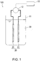
- the apparatus of Embodiment 1 is illustrated in FIG. 1 .
- the apparatus 100 of FIG. 1 includes a cell 11, a power source 12, a controller 13, and an electrode pair 20.
- the electrode pair 20 is disposed inside the cell 11.
- the cell 11 is an electrolytic cell.
- the electrode pair 20 includes a first electrode 21 and a second electrode 22.
- the power source 12 is connected to the first electrode 21 and the second electrode 22.
- Programs for executing each of the processes are stored in a storage unit of the controller 13.
- the controller 13 controls the voltage output from the power source 12 in accordance with those programs.
- An aqueous solution 30 that represents the aqueous solution (S) is stored in the cell 11.
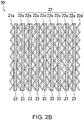
- FIG. 2A A front view of one example of the first electrode 21 is illustrated in FIG. 2A .
- the first electrode 21 of FIG. 2A includes a net-like electrode 21a and a lead 21b connected thereto.
- the second electrode 22 also includes a similar net-like electrode and a lead.
- An expanded metal coated with platinum can be used as the net-like electrodes.
- the first electrode 21 may include a plurality of net-like electrodes, and the second electrode 22 may also include a plurality of net-like electrodes. By adjusting the number of net-like electrodes within each electrode, the ratio between the surface area of the first electrode 21 and the surface area of the second electrode 22 can be altered.
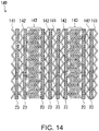
- FIG. 2B illustrates an example in which the first electrode 21 includes a single net-like electrode 21a, and the second electrode 22 includes 9 net-like electrodes 22a. Spacers 23 are disposed between the net-like electrodes, and the net-like electrodes and spacers 23 are stacked against each other. Leads are omitted in FIG. 2B , but the 9 net-like electrodes 22a are connected by leads. In the example in FIG. 2B , the net-like electrode 21a and the net-like electrodes 22a are not disposed alternately, but the two electrodes may also be disposed alternately.
- the controller 13 executes process (i).
- process (i) a DC voltage is applied between the electrodes so that the first electrode 21 becomes the anode and the second electrode 22 becomes the cathode.
- the voltage at this time is a voltage that causes the concentration of free chlorine to increase, and is, for example, a voltage of at least 4 V (in one example a voltage within a range from 5 V to 12 V), or a voltage of at least 7 V (in one example a voltage within a range from 7 V to 9 V).
- an oxygen gas production reaction caused by the electrolysis of water, and a production reaction for chlorine molecules due to chloride ion oxidation (2Cl - ⁇ Cl 2 + 2e - ) occur at the surface of the anode (the first electrode 21). A portion of the produced chlorine molecules become hypochlorous acid and hypochlorite ions.
- a hydrogen gas production reaction caused by the electrolysis of water, and a free chlorine decomposition reaction occur at the surface of the cathode (the second electrode 22).
- the decomposition reaction of free chlorine includes a decomposition reaction of hypochlorous acid and a reduction reaction of chlorine molecules, as shown below. HClO + H + + 2e - ⁇ Cl - + H 2 O Cl 2 + 2e - ⁇ 2Cl -
- aqueous solution 30 treated by process (i) can be used for sterilization (for example, sterilized washing) as required.
- process (ii) a DC voltage is applied between the electrode 21 and electrode 22 so that one of the electrodes becomes the anode and the other becomes the cathode.
- the voltage may be applied so that the first electrode 21 becomes the anode and the second electrode 22 becomes the cathode.
- the voltage may be applied so that the first electrode 21 becomes the cathode and the second electrode 22 becomes the anode.
- the voltage at this time is a voltage that causes the concentration of free chlorine to decrease, and is, for example, a voltage of not more than 3 V (in one example a voltage within a range from 0.9 V to 3.0 V), or a voltage of not more than 1.8 V (in one example a voltage within a range from 1.2 V to 1.8 V).
- process (ii) In a similar manner to the voltage application of process (i), upon the voltage application in process (ii), free chlorine is produced at the anode and free chlorine is eliminated at the cathode.
- process (ii) by applying a lower voltage than that used in process (i), the elimination rate of free chlorine can be adjusted to exceed the production rate of free chlorine.
- process (ii) the concentration of free chlorine decreases upon application of the voltage.
- the aqueous solution (S) for which the concentration of free chlorine has been reduced by process (ii) may be discarded, used for washing the sterilization target, or used for some other application.
- FIG. 3 The reason that the concentration of free chlorine is able to be controlled by the magnitude of the applied voltage is currently not completely clear. However, one possible reason is described using FIG. 3 .
- the graph of FIG. 3 is a schematic graph predicted from test results, and may differ from actuality. Further, FIG. 3 is merely a schematic representation, and takes no consideration of the ratio between the magnitudes of the voltages.
- the horizontal axis in FIG. 3 indicates the electrode potential, whereas the vertical axis in FIG. 3 indicates the reaction current.
- the oxygen gas production reaction occurs more readily at a lower potential than the chloride ion oxidation reaction (free chlorine production reaction). Accordingly, by applying a low voltage, the oxygen gas production reaction can be initiated at the anode with almost no progression of the free chlorine production reaction.
- process (ii) by adjusting the potential of the anode and the potential of the cathode (for example, by setting the DC voltage applied between the two electrodes to a suitable value), the elimination rate of free chlorine at the cathode can be increased to a higher rate than the production rate of free chlorine at the anode. As a result, the concentration of free chlorine can be reduced by process (ii).
- the anode in process (ii) is an electrode in which platinum exists at the surface (a platinum-coated electrode). Platinum exhibits a large difference between the overvoltage for the oxygen gas production reaction and the overvoltage for the chloride ion oxidation reaction, and therefore by using a platinum-coated electrode, the chloride ion oxidation reaction can be suppressed.
- An aqueous solution (S) having a chloride ion concentration not higher than a prescribed value is used.
- an aqueous solution (S) having a low chloride ion concentration By using an aqueous solution (S) having a low chloride ion concentration, the chloride ion oxidation reaction can be suppressed.
- an aqueous solution having a chloride ion concentration of not more than 582 mmol/L may be used, and for example, an aqueous solution having a chloride ion concentration within a range from 17 mmol/L to 582 mmol/L (or within a range from 86 mmol/L to 205 mmol/L in one example) may be used.
- the concentration may be within a range from 0.1 wt% to 3.4 wt% (or within a range from 0.5 wt% to 1.2 wt% in one example).
- the flow rate of the aqueous solution (S) in the vicinity of the anode is increased, thereby promoting the diffusion of hydrogen ions in the vicinity of the anode.
- the average flow rate of the aqueous solution (S) flowing through the inside the electrolytic cell may be set to a value of at least 3.5 mm/s, or at least 6 mm/s. Although there are no particular limitations on the upper limit for the average flow rate, a value of not more than 30 mm/s may be used.
- the anode is moved, thereby agitating the aqueous solution (S) in the vicinity of the anode and promoting the diffusion of hydrogen ions in the vicinity of the anode. For example, by rotating the anode, the aqueous solution (S) in the vicinity of the anode can be agitated.
- J3-3 A structure that causes turbulence flow in the vicinity of the anode is used, thereby agitating the aqueous solution (S) in the vicinity of the anode and promoting the diffusion of hydrogen ions in the vicinity of the anode.
- turbulence may be generated by providing unevenness on the surface of the anode. Further, turbulence may also be generated in the vicinity of the anode by the spacers disposed between the electrodes.
- the curve for the chloride ion oxidation reaction can be moved as illustrated by the alternate long and short dash line A in FIG. 3 .
- the concentration of free chlorine can be efficiently reduced in process (ii).
- An effect can be achieved by implementing any one of the above conditions (J1) to (J3), but the effect can be enhanced by combining a plurality of the conditions. Specifically, combinations of (J1) and (J2), (J1) and (J3), (J2) and (J3), or (J1), (J2) and (J3) may be satisfied. Further, in addition to these conditions, condition (J4) described below may also be satisfied.
- the production rate of free chlorine at the anode can be increased so as to exceed the elimination rate of free chlorine at the cathode.
- the voltage application in process (i) enables the concentration of free chlorine to be increased.
- process (i) and process (ii) may be performed such that condition (J4) described below is satisfied.
- a DC voltage of at least 4 V (for example, within a range from 4 V to 12 V) is applied between the first anode and the first cathode, and in process (ii), a DC voltage within a range from 0.6 V to 3 V is applied between the second anode and the second cathode.
- a DC voltage of at least 5 V (for example, within a range from 5 V to 8 V) is applied in process (i)
- a DC voltage within a range from 0.9 V to 3 V (for example, within a range from 1.2 V to 3 V) is applied in process (ii).
- the potential difference between the electrodes may be altered as the treatment progresses.
- a DC voltage within a range from 1.8 to 3.0 V may be applied between the electrodes, and then when the concentration of free chlorine decreases to 50 mg/L, a DC voltage of at least 1.2 V but less than 1.8 V may be applied.
- the rate of reduction in the concentration of free chlorine may sometimes be able to be increased.
- At least one condition selected from the group consisting of (J1), (J2), (J3) and (J4) may be satisfied.
- processes (i) and (ii) may be performed in such a manner that all of (J1) to (J4) are satisfied.
- process (ii) maybe replaced with a process (ii').
- process (ii') the concentration of free chlorine in the aqueous solution (S) is reduced by applying a DC voltage between two electrodes selected from the plurality of electrodes, in a state where at least one condition selected from the group consisting of (J1), (J2), (J3) and (J4) is satisfied.
- the anode and the cathode in process (i), and the anode and the cathode in process (ii) may all be electrodes in which platinum exists at the electrode surface, and the above condition (J4) may be satisfied.
- an aqueous solution (S) having a chloride ion concentration within a range from 17 mmol/L to 582 mmol/L (or within a range from 86 mmol/L to 205 mmol/L in one example) may be used.
- the average flow rate of the aqueous solution (S) flowing around the periphery of the anode and the cathode in process (ii) may be at least 3.5 mm/s.
- the average flow rate of the aqueous solution (S) inside the cell in which the anode and the cathode are disposed can be considered as the average flow rate of the aqueous solution (S) flowing around the periphery of the anode and the cathode.
- One method of increasing the average flow rate of the aqueous solution (S) flowing through the electrolytic cell involves reducing the cross-sectional area (C) of the electrodes, the cross-sectional area (C) being perpendicular to the direction of flow of the aqueous solution (S). If the amount of the aqueous solution (S) flowing through the electrolytic cell per unit of time is the same, then the smaller the cross-sectional area (C) becomes, the faster the average flow rate of the aqueous solution (S) flowing through the electrolytic cell will become.
- the electrolytic cell and the electrodes disposed therein may be formed as elongated rectangular shapes, with the aqueous solution (S) then set to flow along the lengthwise direction.
- the average flow rate of the aqueous solution (S) flowing through the electrolytic cell may be set to different values in process (i) and process (ii). Specifically, the aforementioned average flow rate in process (i) may be slower than the average flow rate in process (ii). By slowing the average flow rate in process (i), the electric double layer at the electrode surface can be maintained, and the concentration of free chlorine can be increased efficiently. On the other hand, by increasing the average flow rate in process (ii), as described above, the concentration of free chlorine can be efficiently reduced in process (ii).
- Examples of the method for altering the average flow rate between process (i) and process (ii) include the following three methods.
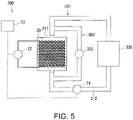
- a first method the pump and valves are simply adjusted to alter the amount of the aqueous solution (S) flowing through the electrolytic cell per unit of time. This configuration illustrated below in FIG. 5 is included in this first method.
- a rectangular electrolytic cell and a rectangular electrode group disposed inside the cell are used, and the direction in which the aqueous solution (S) flows is altered between process (i) and process (ii).
- the aqueous solution (S) is set to flow in a direction perpendicular to the direction in which the cross-sectional area of the electrolytic cell is larger in process (i), and set to flow in a direction perpendicular to the direction in which the cross-sectional area of the electrolytic cell is smaller in process (ii).
- the electrolytic cell is altered between process (i) and process (ii). In this case, a plurality of electrolytic cells having different cross-sectional areas are used.
- Embodiment 2 examples of the method and apparatus for circulating the aqueous solution (S) between an electrolytic cell and a region outside the electrolytic cell are described.
- An apparatus 200 of Embodiment 2 is illustrated in FIG. 4 .
- the apparatus 200 includes a cell 211, a power source 12, a controller 13, a pump 14, and an electrode pair 20.
- the electrode pair 20 is disposed inside the cell 211.
- the cell 211 is an electrolytic cell.
- the power source 12, the controller 13 and the electrode pair 20 were described above in Embodiment 1, and duplicate descriptions of these items are omitted.
- FIG. 4 illustrates an example in which the electrode pair 20 illustrated in FIG. 2B is used.
- An inlet 211a and an outlet 211b are formed in the cell 211.
- a passage 212 is connected between the inlet 211a and the outlet 211b so as to form a circulation passage 301 including a sterilization target 300.
- the aqueous solution 30 that represents the aqueous solution (S) is circulated through the circulation passage 301 by the pump 14 under the control of the controller 13.
- a passage or tank for supplying the aqueous solution 30, and a passage or tank for discharging the aqueous solution 30 following its use in the sterilization may also be connected to the circulation passage 301.
- the inlet 211a and the outlet 211b are formed, and as illustrated in FIG. 4 , the inlet 211a may be formed at the bottom of the cell 211 and the outlet 211b formed at the top of the cell 211.
- gas that is produced at the surfaces of the electrodes can be removed rapidly from the electrode surfaces. As a result, any deterioration in the rate of the electrolysis reaction due to gas on the surfaces of the electrodes can be suppressed.
- the net-like electrodes may be disposed so that the in-plane direction of the net-like electrodes is orthogonal to the flow of the aqueous solution 30.
- the first electrode 21 having a small surface area may be disposed on the side of the inlet 211a, and process (ii) may be performed with a voltage applied such that the first electrode 21 becomes the anode.
- process (I) (the sterilization process including process (i)) is performed in a state where the aqueous solution 30 is circulated between the cell 211 and the sterilization target 300.
- process (II) (the washing process including process (ii)) may also be performed in a state where the aqueous solution 30 is circulated between the cell 211 and the sterilization target 300.
- Process (i) and process (ii) can be executed using the same method as that described for Embodiment 1.
- the sterilization target 300 is tubing.
- the apparatus 200 sterilized washing of the inside of the tubing can be achieved.
- the tubing include the tubing of a blood treatment apparatus.
- the tubing through which the dialysis fluid passes requires sterilization after use.
- the concentration of residual free chlorine in the tubing requires to be reduced before dialysis can be restarted.
- the inside of the tubing can be subjected to sterilized washing by process (I), and the concentration of free chlorine inside the tubing can then be reduced by process (II). Accordingly, the present invention can be used favorably for sterilization of the tubing inside a blood treatment apparatus.
- the sterilization may be performed by providing a sterilization tank at the position of the sterilization target 300, and then immersing the articles that are to be subjected to sterilized washing in the aqueous solution (S) inside that sterilization tank. Further, the cell 11 of Embodiment 1 may be used as the sterilization tank.
- the voltage application times during process (i) and process (ii) may be set in accordance with the desired purpose.
- a sensor for monitoring the concentration of free chlorine may be placed inside the cell or inside the flow passage.
- the controller may control the magnitude of the voltage and the time of the voltage application based on the output from the sensor. Further, the controller may also apply the voltage in accordance with predetermined conditions.
- the apparatus may be constructed so that the cell 211 forms a part of two circulation passages.
- a circulation passage 302 is formed in parallel with the circulation passage 301.
- the flow volume of the aqueous solution (S) through the circulation passage 302 is controlled by a pump 303 provided within the circulation passage 302.
- the flow rate (average flow rate) of the aqueous solution (S) inside the cell 211 can be increased independently of the flow rate of the aqueous solution (S) through the circulation passage 301.
- the concentration of free chlorine was measured by the DPD method (diethyl-para-phenylenediamine method). Specifically, measurement was performed by a free chlorine measurement method (Method 8021 described by Hach Company) using an absorption photometer (DR3900) manufactured by Hach Company. In this method, the sample and a reagent for measuring the concentration of free chlorine are placed in a sample cell, and the concentration of free chlorine is calculated by measuring the absorbance of the sample which has developed color due to the reagent.
- DPD method diethyl-para-phenylenediamine method
- Example 1 the relationship between the applied voltage in process (i) and the concentration of free chlorine was investigated.
- Example 1 an electrode pair having the configuration illustrated in FIG. 2B was used. Electrodes (length: 35 mm, width: 54 mm, thickness: 1.8 mm) formed from titanium expanded metal that had been plated with platinum were used for the net-like electrodes that formed the anode and the cathode. As illustrated in FIG. 2B , the first electrode 21 (the anode in this example) was prepared using a single net-like electrode 21a, whereas the second electrode 22 (the cathode in this example) was prepared using 9 net-like electrodes 22a. With the electrodes in Example 1, the surface area of the cathode was about 9 times the surface area of the anode. Net-like resin spacers (thickness: 0.8 mm) were disposed between each of the electrodes.
- an aqueous solution of sodium chloride (physiological saline solution) with a concentration of 0.9 wt% was prepared.
- This aqueous solution was subjected to process (i). Specifically, the electrodes described above were placed in a beaker containing the aqueous solution, and a DC voltage was applied between the first electrode 21 (anode) and the second electrode 22 (cathode). The voltage application was performed while the aqueous solution was stirred with a stirrer. Further, the aqueous solution inside the beaker was circulated at a flow rate of 150 mL/minute using a pump. The total volume of the aqueous solution was 1 L. In Example 1, four types of tests were performed using different voltage application methods. Specifically, the voltage was applied under the four sets of conditions described below.
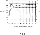
- FIG. 7 the changes in the ORP (oxidation reduction potential) and the pH of the aqueous solution when a voltage of 5 V was applied are illustrated in FIG. 7 .
- the ORP and the pH increased in the initial stages of voltage application, but were then substantially constant thereafter.
- Example 2 the relationship between the applied voltage in process (ii) and the concentration of free chlorine was investigated. In Example 2, with the exception of altering the applied voltage, tests were performed under the same conditions as Example 1.
- Example 2 a voltage was first applied for 15 minutes so that a constant current of 2 A flowed between the first electrode 21 (anode) and the second electrode 22 (cathode) described in Example 1 (process (i)).
- the voltage application in process (i) caused the concentration of free chlorine in the aqueous solution (physiological saline solution) to reach about 200 mg/L (specifically, within a range from 181 to 251 mg/L).
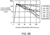
- Example 2 7 tests were performed with different applied voltages. Specifically, tests were performed in which the fixed voltage applied between the first electrode 21 (anode) and the second electrode 22 (cathode) was set to 0.6 V (Test 2-1), 0.9 V (Test 2-2), 1.2 V (Test 2-3), 1.5 V (Test 2-4), 1.8 V (Test 2-5), 2.4 V (Test 2-6) and 3.0 V (Test 2-7). Then, the relationship between the concentration of free chlorine in the aqueous solution and the voltage application time was investigated. The measurement results are illustrated in FIG. 8A . Further, a graph in which the vertical axis of FIG. 8A has been displayed as a logarithmic scale is illustrated in FIG.
- FIG. 8A and FIG. 8B the voltage application time from 0 to 15 minutes corresponds with process (i), and the subsequent time period corresponds with process (ii).
- the voltages shown in the legends of FIG. 8A and FIG. 8B represent the voltages applied in process (ii).
- the concentration of free chlorine decreased as a result of performing process (ii).
- the concentration of free chlorine decreased greatly when the applied voltage was within a range from 0.9 to 3.0 V, and decreased even more when the applied voltage was within a range from 1.2 to 3.0 V (and particularly within a range from 1.2 V to 1.8 V).
- the salt concentration in the aqueous solution was high, setting the applied voltage within a range from 1.8 V to 3.0 V enabled the rate of reduction in the concentration of free chlorine to be increased.
- FIG. 9 The changes in the ORP and the pH of the aqueous solution in Test 2-5 (an applied voltage of 1.8 V in process (ii)) are illustrated in FIG. 9 .
- an applied voltage of 1.8 V in process (ii) is illustrated in FIG. 9 .
- the ORP increased and the pH decreased in the period when the voltage application time shown in FIG. 9 was between 15 minutes (the start of process (ii)) and 30 minutes, but after that period, there was no significant change in either property.
- Example 3 tests were performed in which the ratio between the surface area of the anode and the surface area of the cathode was altered.
- the second electrode 22 described in Example 1 namely an electrode containing 9 net-like electrodes 22a
- the net-like electrode of the anode the net-like electrode 21a described in Example 1 was used, but the number of these net-like electrodes constituting the anode was varied from one to nine.
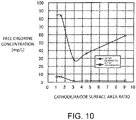
- the configurations of the electrodes used in Example 3 are shown in Table 1. As shown in Table 1, the value of (surface area of cathode)/(surface area of anode) was altered within a range from 1.0 (Test 3-5) to 9.0 (Test 3-1).
- Example 3 With the exception of changing the configuration of the electrode pair, tests were performed under the same conditions as Test (2-3) of Example 2. Specifically, a voltage was first applied for 15 minutes so that a constant current of 2 A flowed between the anode (the first electrode 21) and the cathode (the second electrode 22) (process (i)). The voltage application in process (i) caused the concentration of free chlorine to reach about 200 mg/L (specifically, within a range from 194 to 251 mg/L).
- process (ii) of any of Tests 3-1 to 3-5 was performed. Specifically, a constant voltage of 1.2 V was applied between the anode (the first electrode 21) and the cathode (the second electrode 22). Then, the change in the concentration of free chlorine in the aqueous solution as a result of process (ii) was measured. The measurement results are illustrated in FIG. 10 . As illustrated in FIG. 10 , at a point 60 minutes after the start of the voltage application of process (ii), the concentration of free chlorine had decreased greatly in those cases where the cathode/anode surface area ratio was within a range from 3.0 to 9.0.
- results in FIG. 10 indicate that by setting the cathode/anode surface area ratio within a range from 3.0 to 9.0, the rate of reduction in the concentration of free chlorine can be increased. Further, the results in FIG. 10 also indicate that in those cases where the voltage is applied for a long period of time, the concentration of free chlorine can be reduced satisfactorily even when the cathode/anode surface area ratio is large (namely, even if the area of anode used is small).
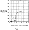
- Example 4 the relationship between the concentration of the alkali metal chloride in the aqueous solution and the change in the concentration of free chlorine was investigated. Specifically, processes (i) and (ii) were performed using different concentrations of the alkali metal chloride in the aqueous solution.
- the electrode pair used had the same configuration as the electrode pair of Example 1.
- a plurality of aqueous solutions having different concentrations of sodium chloride were prepared. Specifically, a plurality of aqueous solution of sodium chloride having concentrations within a range from 0.7 wt% to 10.8 wt% were prepared. Process (i) was performed using each of these aqueous solution of sodium chloride. Specifically, the electrode pair described above was placed in a beaker containing 200 mL of the aqueous solution, and a voltage was applied for 3 minutes so that a constant current of 2 A flowed between the first electrode 21 (anode) and the second electrode 22 (cathode). The voltage application was performed while the aqueous solution was stirred with a stirrer. As a result of this voltage application, the concentration of free chlorine in the aqueous solution reached about 200 mg/L.
- process (ii) was performed.
- a constant voltage of 1.2 V was applied between the first electrode 21 (anode) and the second electrode 22 (cathode).
- the change in the concentration of free chlorine due to process (ii) was measured.
- the concentration of free chlorine after process (ii) is illustrated in FIG. 11 .
- the sodium chloride concentration and the length of time of the voltage application in process (ii) were as shown in Table 2.
- Test 4-12 Sodium chloride concentration (wt%) Voltage application time (minutes) Test 4-1 0.7 40 Test 4-2 0.9 30 Test 4-3 0.9 40 Test 4-4 1.8 50 Test 4-5 2.0 60 Test 4-6 2.7 Test 4-7 3.0 Test 4-8 3.2 Test 4-9 3.6 Test 4-10 4.0 Test 4-11 7.2 Test 4-12 10.8
- the concentration of free chlorine decreased greatly when the chloride ion concentration was within a range from 120 mmol/L to 548 mmol/L (and particularly within a range from 120 mmol/L to 514 mmol/L).
- Example 5 the anode was changed, and the same tests as Example 4 were performed.
- the concentration of the aqueous solution of sodium chloride was varied within a range from 0.9 wt% to 3.6 wt% (specifically, 0.9 wt%, 1.35 wt%, 1.8 wt% and 3.6 wt%), and the voltage application was performed for 60 minutes in process (ii).
- tests were performed under the same conditions as those described for Example 4.
- Example 5 an electrode in which iridium oxide existed at the electrode surface was used as the first electrode 21 (anode). Specifically, an electrode (JP-330) manufactured by De Nora Permelec Ltd. was used. With the exception of the anode, the remaining portions of the electrode pair had the same configuration as the electrode pair of Example 1.
- Example 5 The results of Example 5 are illustrated in FIG. 12 .
- the results of Example 4 are also shown for the purpose of comparison.
- the concentration of free chlorine decreased greatly when the sodium chloride concentration was lower than about 1.5 wt%.
- the concentration of free chlorine decreased greatly when the sodium chloride concentration was lower than about 3.4 wt%.
- Example 6 a flow-type electrolytic cell similar to the electrolytic cell 211 illustrated in FIG. 4 was used, and tests were conducted to increase and decrease the concentration of free chlorine.
- the same electrode pair as that used in Example 1 was used.
- aqueous solution an aqueous solution of sodium chloride (physiological saline solution) with a concentration of 0.9 wt% was used, and 200 mL of this aqueous solution was circulated through a circulation passage including the electrolytic cell.
- Process (i) and (ii) were performed in this state.
- a voltage was applied for 4 minutes so that a constant current of 2 A flowed between the first electrode 21 (anode) and the second electrode 22 (cathode). This voltage application caused the concentration of free chlorine in the aqueous solution to reach about 200 mg/L.
- a voltage of 1.2 V was applied for 60 minutes between the first electrode 21 (anode) and the second electrode 22 (cathode).
- Example 6 processes (i) and (ii) were performed with the average flow volume of the aqueous solution through the inside of the electrolytic cell set to 150 mL/minute, 400 mL/minute and 800 mL/minute. Conversion of these flow volumes to average flow rates inside the electrolytic cell yields corresponding flow rates of 1.3 mm/s, 3.5 mm/s and 7.1 mm/s respectively.
- the concentration of free chlorine after the voltage application of process (ii) is illustrated in FIG. 13 . As illustrated in FIG. 13 , a tendency was observed for a greater reduction in the concentration of free chlorine when the flow rate was faster. Specifically, the concentration of free chlorine decreased greatly when the flow rate was 3.5 mm/s or more.
- Example 7 describes an example in which the surface area of the second cathode was set to a larger value than the surface area of the first cathode.
- the configuration of the electrode unit 140 used in Example 7 is illustrated schematically in FIG. 14 . Further, the electrolytic cell used in Example 7 is illustrated schematically in FIG. 15 .
- the electrode unit 140 of FIG. 14 includes a first electrode 141, a second electrode 142, a third electrode 143 and spacers 23.
- the first to third electrodes 141 to 143 are each composed of the same types of net-like electrodes. However, the number of net-like electrodes within each of the electrodes differs.
- the first electrode 141 was formed of 3 net-like electrodes.
- the second electrode 142 was formed of 4 net-like electrodes.
- the third electrode 143 was formed of 22 net-like electrodes. In FIG. 14 and FIG. 15 , in order to simplify the illustrations, the number of net-like electrodes constituting the third electrode 143 has been reduced.
- each net-like electrode a platinum-coated electrode having a size of 80 mm ⁇ 60 mm and a thickness of 0.5 mm was used.
- Each spacer used a resin net-like spacer having a size of 80 mm ⁇ 60 mm and a thickness of 0.5 mm.
- the electrode unit 140 was positioned inside the cell 211 so that each of the net-like electrodes was parallel to the flow direction of the aqueous solution.
- a circulation passage including the inlet 211a and the outlet 211b was formed, and 1.5 L of saline solution was circulated through this circulation passage.
- a solution having a concentration of free chlorine of about 240 to 250 ppm (about 240 to 250 mg/L) and a concentration of NaCl of 0.65 wt% was used.
- the flow volume of the saline solution through the circulation passage was set to 0.3 L/minute. Process (ii) was performed in a state where the saline solution was being circulated.
- Example 7 process (ii) was performed with various values for the ratio between the surface area of the second anode and the surface area of the second cathode.
- the electrode surface area ratio in each of the tests is shown in Table 3. [Table 3] Number of net-like electrodes Surface area ratio second cathode/second anode Second cathode Second anode Test 7-1 26 3 26/3 Test 7-2 16 3 16/3 Test 7-3 4 3 4/3
- the first electrode 141 of the electrode unit 140 was used as the second anode, and the second electrode 142 and third electrode 143 were used as the second cathode.
- (surface area of second cathode)/(surface area of second anode) 26/3.
- the surface area of the second cathode was about 9 times that of the surface area of the second anode.
- the first electrode 141 was used as the second anode
- the second electrode 142 was used as the second cathode
- no voltage was applied to the third electrode 143.
- Test 7-2 with the exception of altering the number of net-like electrodes that constitute the third electrode 143 of the electrode unit 140 to 12, testing was performed in the same manner as Test 7-1.
- the electrode unit was thinner as a result of reducing the number of net-like electrodes that constitute the third electrode 143, thus generating space inside the cell 211.
- a spacer 23 was positioned in that space.
- process (i) may be conducted without applying a voltage to the third electrode 143.
- process (i) may be performed using the first electrode 141 as the first anode and the second electrode 142 as the first cathode.
- Example 8 process (i) and process (ii) were performed, and the change in the concentration of free chlorine was measured.
- process (ii) of Example 8 the voltage applied between the electrodes was reduced in a stepwise manner.
- Example 8 the same electrode unit and circulation passage as those used in Test 7-1 of Example 7 were used. A saline solution having a concentration of NaCl of 0.65 wt% was circulated through the circulation passage, and processes (i) and (ii) were performed in that state.
- process (i) a DC voltage of 6 V was applied between the first anode and the first cathode.
- the magnitude of the DC voltage applied between the second anode and the second cathode was initially set to 2 V, and was subsequently reduced to 1.5 V, and then to 1.2 V.
- the change in the concentration of free chlorine is illustrated in FIG. 17A .
- a partial enlargement of FIG. 17A is shown in FIG. 17B .
- the final concentration of free chlorine was able to be reduced to 1 ppm or less.
- the concentration of free chlorine was able to be reduced to an extremely low level in a short period of time.
- the present invention can be used in a method and apparatus for controlling the concentration of free chlorine, and can also be used in a sterilization method and sterilization apparatus using said method and apparatus.
Description
- The present invention relates to a method and an apparatus for controlling the concentration of free chlorine, and also relates to a sterilization method and a sterilization apparatus which utilize said method and apparatus.
- Methods for performing sterilization by producing hypochlorite from salt water have already been proposed. For example,
JP H05-179475 A - When sterilization is performed using hypochlorite, it is sometimes preferable to remove the residual hypochlorite after the sterilization. As a result, methods for removing hypochlorite have been proposed. For example,
JP H04-78486 A JP H04-78486 A -
JP 2006-239531 A JP 2006-239531 A -
JP HI 1-290855 A -
EP 1340841 A1 proposes an electrolytic cell for ozone generation using two grid electrodes supplied by a DC power source and the concentration of ozone is controlled solely through high oxygen overvoltage materials. -
US 4127458 A discloses a process for recovering a platinum group metal in an aqueous effluent by applying two different potentials, namely a potential of at least 4 V to the cathode and a potential of at least 7.5 V to the anode for the destruction of complexes. -
WO 2008/105613 A1 discloses a method of manufacturing medical sterilized normal saline is disclosed by using electrodes having platinum coated rods and slots in anode and cathode electrode plates being powered by 2.4 V to 3.3 V DC power. -
JP H06 153744 A -
EP 1903 128 A2 discloses a membrane electrode assembly having two electrodes, an electrolytic unit, an electrolytic water ejecting apparatus containing the electrolytic unit to be used for sterilization. The sprayer is powered with three different power supplies, namely; a device which generates power for electrolysis upon trigger operation, a rechargeable battery and an adapter capable of supplying DC power from an AC power source. -
WO 2010/027825 A2 discloses an electrochemical method for chlorine-based oxidant generation using three compartmental apparatus each having various pH values. The concentration of ions are not only adjusted by applying various potential differences between the anode and cathode, namely 1 V -15 V, or 2 V-10 V, or 4 V-9 V but also using different feeds supplied to the compartments. - In light of these circumstances, it is one object of the present invention to provide a method that can easily control the concentration of free chlorine, and a novel apparatus that can easily control the concentration of free chlorine.
- As a result of investigations aimed at achieving the above object, the inventors of the present invention discovered a phenomenon not previously known. The present invention is based on this novel finding.
- Thus, the object is achieved by the features of the respective independent claims. Further embodiments are defined in the respective dependent claims.
- By using the methods and apparatus of the present invention, the concentration of free chlorine in an aqueous solution can be controlled easily. Further, in the sterilization method and sterilization apparatus of the present invention, a sterilization target can be sterilized using an aqueous solution having an increased concentration of free chlorine.
-
-
FIG. 1 is a schematic view illustrating one example of an apparatus of the present invention. -
FIG. 2A is a front view schematically illustrating one example of an electrode used in the present invention. -
FIG. 2B is a diagram schematically illustrating one example of an electrode pair used in the present invention. -
FIG. 3 is a conceptual drawing for describing the present invention. -
FIG. 4 is a schematic view illustrating another example of an apparatus of the present invention. -
FIG. 5 is a schematic view illustrating yet another example of an apparatus of the present invention. -
FIG. 6 is a graph illustrating test results from Example 1. -
FIG. 7 is a graph illustrating other test results from Example 1. -
FIG. 8A is a graph illustrating test results from Example 2. -
FIG. 8B is another graph illustrating test results from Example 2. -
FIG. 9 is a graph illustrating other test results from Example 2. -
FIG. 10 is a graph illustrating test results from Example 3. -
FIG. 11 is a graph illustrating test results from Example 4. -
FIG. 12 is a graph illustrating test results from Example 5. -
FIG. 13 is a graph illustrating test results from Example 6. -
FIG. 14 is a diagram schematically illustrating the structure of one example of an electrode unit used in Example 7. -
FIG. 15 is a diagram schematically illustrating the structure of one example of an electrolytic cell used in Example 7. -
FIG. 16 is a graph illustrating results from Example 7. -
FIG. 17A is a graph illustrating results from Example 8. -
FIG. 17B is a partial enlargement of the graph illustrated inFIG. 17A . - Embodiments of the present invention are described below. In the following description, examples of embodiments of the present invention are described, but the present invention is not limited to the examples described below. In the following description, specific numerical values and materials are sometimes presented as examples, but other numerical values and materials may also be employed, provided that the effects of the present invention can be obtained. In descriptions using the drawings, identical portions are labeled with the same reference signs, and duplicate descriptions may sometimes be omitted.
- One example of the method of the present invention for controlling the concentration of free chlorine (the available chlorine concentration) is described below. In this method, a plurality of electrodes are used to control the concentration of free chlorine. This method includes a process of (i) and a process of (ii) described below in that order. The plurality of electrodes is typically composed of two electrodes that constitute one electrode pair. However, the present invention may also include other electrodes besides those two electrodes.
- In process (i), the potentials of two electrodes selected from the plurality of electrodes are adjusted so that the two electrodes function as an anode and a cathode in an aqueous solution containing chloride ions, thereby increasing the concentration of free chlorine in the aqueous solution. In the following description, the aqueous solution treated by processes (i) and (ii) is sometimes termed "the aqueous solution (S)". Further, the anode and the cathode in process (i) are sometimes termed "the first anode" and "the first cathode" respectively.
- From another viewpoint, in process (i), the potential of the first anode and the potential of the first cathode in the aqueous solution (S) comprising chloride ions are adjusted, thereby increasing the concentration of free chlorine in the aqueous solution (S). The first anode and the first cathode are composed of one portion and one other portion of the plurality of electrodes, respectively. The plurality of electrodes may also include an electrode that constitutes neither the first anode nor the first cathode.
- Examples of the adjustment of the potentials of the two electrodes include those cases in which the potential difference between the two electrodes is adjusted, and include, for example, the case in which the potential difference between the two electrodes is adjusted by applying a DC voltage between the two electrodes (this also applies in process (ii)). In other words, in one example of process (i), a DC voltage is applied between the first anode and the first cathode, and the potentials of the electrodes are adjusted only by that voltage application.
- In process (i), chloride ions are oxidized and chlorine molecules are produced at the surface of the anode. These chlorine molecules react with the water to produce hypochlorous acid and hypochlorite ions. In other words, the voltage application in process (i) increases the concentration of free chlorine (dissolved chlorine, hypochlorous acid and hypochlorite ions).
- The aqueous solution (S) contains chloride ions. One preferred example of the aqueous solution (S) is water containing a dissolved metal chloride such as an alkali metal chloride. Examples of alkali metal chlorides include sodium chloride (NaCl) and potassium chloride (KCl). One example of the aqueous solution (S) is an aqueous solution in which is dissolved at least one compound selected from among sodium chloride and potassium chloride, and the aqueous solution (S) may be a sodium chloride aqueous solution. Further, other examples of the aqueous solution (S) include physiological saline solution (a sodium chloride aqueous solution) and liquids used in blood treatment apparatus (such as the dialysis fluid used in an artificial dialysis apparatus). The main component of dialysis fluid is sodium chloride, and the concentration of the sodium chloride is about 0.7 wt%. Other examples of the aqueous solution (S) include tap water and ground water.
- If the chloride ion concentration is too low, then in process (i), the concentration of free chlorine may not be able to be increased sufficiently, or the voltage drop in the aqueous solution (S) may become too large. On the other hand, if the chloride ion concentration is too high, then the time required to reduce the concentration of free chlorine in process (ii) described below may sometimes lengthen. Accordingly, the chloride ion concentration in the aqueous solution (S) is preferably within a suitable range. The chloride ion concentration in the aqueous solution (S) may be within a range from 17 mmol/L to 582 mmol/L. The concentration of a sodium chloride aqueous solution (molar mass of sodium chloride: 58.4 g/mol) that yields a chloride ion concentration of 17 mmol/L is about 0.1 wt% (0.017 × 58.4 × 100/1000). The concentration of a sodium chloride aqueous solution that yields a chloride ion concentration of 582 mmol/L is about 3.4 wt% (0.582 × 58.4 × 100/1000). When the aqueous solution (S) is an aqueous solution of an alkali metal chloride (for example, sodium chloride and/or potassium chloride), the concentration may fall within a range from 0.7 wt% to 7.2 wt%.
- In process (ii), the potentials of two electrodes selected from the plurality of electrodes are adjusted so that the two electrodes function as an anode and a cathode in the aqueous solution (S), thereby decreasing the concentration of free chlorine in the aqueous solution (S). In the following description, the anode and the cathode in the voltage application of process (ii) are sometimes termed "the second anode" and "the second cathode" respectively.
- From another viewpoint, in process (ii), the potential of the second anode and the potential of the second cathode in the aqueous solution (S) are adjusted, thereby decreasing the concentration of free chlorine in the aqueous solution (S). The second anode and the second cathode are composed of one portion and one other portion of the plurality of electrodes, respectively. The plurality of electrodes may also include an electrode that constitutes neither the second anode nor the second cathode.
- In the method of the present invention, the potential difference between the two electrodes in process (ii) (the difference between the potential of the second anode and the potential of the second cathode) is set to a value smaller than the potential difference between the two electrodes in process (i) (the difference between the potential of the first anode and the potential of the first cathode).
- In process (ii), the free chlorine component is decomposed at the surface of the second cathode, resulting in a reduction in the concentration of free chlorine in the aqueous solution (S). Accordingly, by increasing the surface area of the second cathode, the amount of free chlorine can be reduced efficiently. For example, the surface area of the second cathode in process (ii) may be larger than the surface area of the second anode in process (ii). By making the surface area of the second cathode larger than the surface area of the second anode, the overall electrode size can be reduced and the rate of reduction in the concentration of free chlorine can be increased.
- The surface area of the second cathode may be larger than the surface area of the second anode. In one example, the surface area of the second cathode is larger than the surface area of the first cathode, and the surface area of the second cathode is also larger than the surface area of the second anode. In other words, the surface area of the second cathode may be larger than both the surface area of the first cathode and the surface area of the second anode. The surface area of the second cathode may be at least twice, or at least 3 times, the surface area of the second anode, and may be not more than 20 times, or not more than 12 times, or not more than 9 times, the surface area of the second anode. For example, the surface area of the second cathode may be within a range from 2 to 12 times, or within a range from 3 to 12 times, or within a range from 3 to 9 times, the surface area of the second anode.
- In one example, the conditions (1) and (2) described below may be satisfied, and the condition (3) may also be satisfied.
- (1) The surface area of the first cathode is within a range from 0.5 to 2 times the surface area of the first anode.
- (2) The surface area of the second cathode is within a range from 2 to 12 times, or within a range from 3 to 12 times, or within a range from 3 to 9 times, the surface area of the second anode.
- (3) The surface area of the first anode is within a range from 0.5 to 2 times the surface area of the second anode.
- In one example, the plurality of electrodes may include a first electrode used as the first anode, a second electrode used as the first cathode, and a third electrode. In this example, a voltage need not be applied to the third electrode in process (i), and the third electrode may be used as at least a portion of the second cathode in process (ii). For example, in process (ii), the first electrode may be used as the second anode, and the second and third electrodes may be used as the second cathode. In one preferred example, the surface area of the third electrode is set within a range from 2 to 11 times the surface area of the first electrode, and the surface area of the third electrode is set within a range from 2 to 11 times the surface area of the second electrode. An example using the third electrode is described in Example 7.
- In process (i), the potentials of the electrodes are adjusted so that the concentration of free chlorine increases. In contrast, in process (ii), the potentials of the electrodes are adjusted so that the concentration of free chlorine decreases. The potentials that cause the concentration of free chlorine to increase and decrease may vary depending on the solute and concentration of the aqueous solution (S), and the material of the electrodes. Accordingly, the potentials are preferably adjusted with due consideration of these factors.
- In those cases where the potentials are adjusted by controlling the magnitude of the DC voltage applied between the anode and the cathode, a DC voltage that causes an increase in the concentration of free chlorine is applied in process (i), and a DC voltage that causes a decrease in the concentration of free chlorine is applied in process (ii). In such cases, the magnitude of the DC voltage applied between the electrodes in process (ii) is set to a smaller value than the magnitude of the DC voltage applied between the electrodes in process (i).
- There are no particular limitations on the shapes of the anodes and cathodes used in process (i) and process (ii). The electrodes may be plate-like electrodes, or some other shape. From the viewpoint of accelerating the reaction at the electrode surface, an electrode having a large surface area may be used, or an electrode may be used which has passages formed therein through which the aqueous solution (S) can pass. For example, an electrode formed by grouping a series of metal wires (such as a net-like electrode), or a porous electrode may be used. Furthermore, an electrode having through-holes formed therein, such as an electrode that uses a punched metal or an expanded metal, may also be used.
- The anode and the cathode may each be an electrode having a shape that extends in two dimensions. For example, the anode and the cathode may each be a flat plate electrode having through-holes formed therein, or may be a net-like electrode. As illustrated in
FIG. 4 , these types of flat electrodes may be positioned so that the in-plane direction of the electrodes is arranged orthogonally relative to the flow direction of the aqueous solution (S). Alternatively, as illustrated inFIG. 15 , the electrodes may be arranged so that the in-plane direction of the electrodes is parallel to the flow direction of the aqueous solution (S). - In the present invention, the plurality of electrodes may be composed of two electrodes. In this description, in those cases where a plurality of electrodes that are connected by wiring or the like and are at substantially the same potential function as a single anode or a single cathode, that plurality of electrodes is counted as a single electrode.
- The two electrodes for which the potentials are adjusted in process (i) (the first anode and the first cathode) may be used as the two electrodes for which the potentials are adjusted in process (ii) (the second anode and the second cathode). For example, the anode and the cathode in process (i) may be used as the anode and the cathode respectively in process (ii). In other words, voltages may be applied in process (i) and process (ii) without altering the anode or the cathode (without altering the direction of voltage application). Further, the anode and the cathode in process (i) may be used as the cathode and the anode respectively in process (ii). In other words, in process (ii), the voltage may be applied in the reverse direction to that used in process (i). Furthermore, at least one of the anode and the cathode in process (ii) may be a different electrode from either the anode or the cathode in process (i).
- In one example of the present invention, a DC voltage is applied between the two electrodes (the first anode and the first cathode) for which the potentials are to be adjusted in process (i), thereby adjusting the potentials of the two electrodes, and a DC voltage is then applied between the two electrodes (the second anode and the second cathode) for which the potentials are to be adjusted in process (ii), thereby adjusting the potentials of those two electrodes.
- One example of a preferred electrode is an electrode in which platinum exists at the surface. In the following description, an electrode in which platinum exists at the surface (for example, an electrode having a surface coated with platinum) is sometimes termed a "platinum-coated electrode". A platinum-coated electrode can be used favorably as the anode of process (ii). All of the plurality of electrodes may be platinum-coated electrodes. Other examples of the electrode include electrodes in which iridium oxide exists at the surface (for example, an electrode having a surface coated with iridium oxide). In the following description, an electrode in which iridium oxide exists at the surface is sometimes termed an "iridium oxide-coated electrode".
- In process (ii) in which the concentration of free chlorine is reduced, the use of a platinum-coated electrode as the anode is preferable. Further, in process (i) in which the concentration of free chlorine is increased, the use of an iridium oxide-coated electrode as the anode is preferable. In one example of the present invention, a platinum-coated electrode and an iridium oxide-coated electrode may be used as the plurality of electrodes. In this example, in process (i), a DC voltage is applied between the two electrodes with the iridium oxide-coated electrode used as the anode and the platinum-coated electrode used as the cathode, whereas in process (ii), a DC voltage is applied between the two electrodes with the platinum-coated electrode used as the anode and the iridium oxide-coated electrode used as the cathode. By employing this configuration, the concentration of free chlorine can be increased efficiently in process (i), and the concentration of free chlorine can be reduced efficiently in process (ii).
- A spacer may be disposed between the electrodes. One of the purposes of providing a spacer is to prevent short-circuits between the anode and the cathode. Further, providing a spacer facilitates the flow of the aqueous solution (S) between the electrodes. An insulating spacer may be used as the spacer, and for example, a resin spacer may be used. One example of a preferred spacer is a net-like resin spacer.
- Each of process (i) and process (ii) may, independently, be conducted using a batch method or a flow method. In the batch method, the aqueous solution (S) inside the electrolytic cell in which the anode and the cathode are disposed undergoes substantially no movement during each process. In contrast, in the flow method, the aqueous solution (S) is moved between the electrolytic cell and a region outside the electrolytic cell during each process. In a typical flow method, the aqueous solution (S) flows continuously through the electrolytic cell.
- The difference between the potential of the first anode and the potential of the first cathode in process (i) may be at least 4 V, at least 5 V, or 7 V or more, and may be not more than 60 V, not more than 20 V, or 12 V or less. The difference between the potential of the second anode and the potential of the second cathode in process (ii) may be less than 4 V, 3 V or less, or 2 V or less, and may be at least 0.6 V or 1.2 V or more.
- In one example, a DC voltage of at least 4 V (for example, a voltage within a range from 4 V to 12 V or within a range from 5 V to 12 V) is applied between the first anode and the first cathode in process (i), and a DC voltage within a range from 0.6 V to 3 V (for example, within a range from 1.2 V to 3 V) is applied between the second anode and the second cathode in process (ii). In this example, the first anode, the first cathode, the second anode and the second cathode may each be an electrode in which platinum exists at the electrode surface.
- In one example of the present invention, the difference between the potential of the second anode and the potential of the second cathode may be gradually reduced in process (ii). By using this configuration, the concentration of free chlorine can sometimes be reduced in a shorter period of time, and the concentration of free chlorine can sometimes be reduced to an extremely low level. In those cases where the potential difference is reduced gradually, the potential difference may be reduced in a continuous manner, or the potential difference may be reduced in a stepwise manner. For example, the potential difference between the second anode and the second cathode may be set within a range from 2 V to 3 V in the initial stage of process (ii), and then the potential difference may be changed to a value of at least 1.2 V but less than 2 V. When the potential difference is reduced gradually, the final potential difference may be set within a range from 0.6 V to less than 1.2 V. For example, the potential difference between the second anode and the second cathode may be set within a range from 2 V to 3 V in the initial stage of process (ii), and then the potential difference may be changed to a value of at least 0.6 V but less than 1.2 V at the end of process (ii).
- Unlike the method of
Patent Document 1, in the method of the present invention, the concentration of free chlorine can be controlled without using an ion exchange material such as an ion exchange membrane. As a result, maintenance of the apparatus used for implementing the method of the present invention is simple. However, in the present invention, an ion exchange material may be used if necessary. - One example of the sterilization method of the present invention is described below. The sterilization method of the present invention is a method of performing sterilization using an aqueous solution containing free chlorine. This sterilization method includes the method of the present invention for controlling the concentration of free chlorine. In other words, this sterilization method includes processes (i) and (ii) described above in that order. Because the matters described above in relation to the method for controlling the concentration of free chlorine can also be applied to the sterilization method of the present invention, duplicate descriptions may sometimes be omitted. Further, the matters described in relation to the sterilization method of the present invention can also be applied to the method for controlling the concentration of free chlorine. Further, from another viewpoint, the term sterilization used in the present description can be replaced with the term washing. For example, the sterilization method and the sterilization apparatus of the present invention can be termed a washing method and a washing apparatus.
- The sterilization method of the present invention includes a process of (I). In process (I), a sterilization target is sterilized using the aqueous solution (S) that has been treated in process (i). Because the aqueous solution (S) that has been treated in process (i) has an increased concentration of free chlorine, sterilization can be performed by process (I).
- The sterilization method of the present invention may include, after process (I), process (II) washing the sterilization target using the aqueous solution (S) that has been treated in process (ii). The aqueous solution (S) that has been treated in process (ii) has a reduced concentration of free chlorine. Accordingly, executing process (II) can prevent a high concentration of free chlorine from being retained in the sterilization target. In those cases where process (II) is not performed, and the concentration of free chlorine is reduced using a washing water, a large amount of water requires to be used for the washing, but by performing process (II), the amount of such water used can be reduced.
- There are no particular limitations on the target that is sterilized by the sterilization method of the present invention. Examples of the sterilization target include medical instruments, medical equipment, tableware, and other equipment and items. Examples of the medical instruments include blood treatment apparatus (for example, blood purification devices such as artificial dialysis devices). In particular, the tubing in a blood treatment apparatus (for example, the tubing through which the blood or the dialysis fluid flows) can be sterilized favorably. The sterilization method of the present invention is not limited to the medical field, and can also be used in other industrial fields.
- In one example of the sterilization method of the present invention, the application of voltage in processes (i) and (ii) is conducted inside an electrolytic cell, and the sterilization target is sterilized by performing processes (i) and (ii) while the aqueous solution (S) is circulated between the electrolytic cell and the sterilization target. In other words, in this example, the sterilization is performed by the aqueous solution (S) that is circulated between the electrolytic cell and the sterilization target. By employing this configuration, satisfactory sterilization can be achieved with a minimal amount of the aqueous solution (S). Further, the amount of waste liquid when the aqueous solution (S) is discarded can be reduced. In one example of this configuration, the sterilization target is the tubing of a blood treatment apparatus.
- The method of the present invention may also include, either between process (i) and process (ii), or after process (ii), maintaining the concentration of free chlorine in the aqueous solution (S) within a fixed range by adjusting the potentials of at least two electrodes selected from the plurality of electrodes. In the following description, this process may sometimes be termed "process (x)".
- From another viewpoint, process (x) is adjusting the potential of a third anode and the potential of a third cathode in the aqueous solution (S), thereby maintaining the concentration of free chlorine in the aqueous solution (S) within a fixed range. The third anode and the third cathode are composed of one portion and one other portion of the plurality of electrodes, respectively.
- When the aqueous solution (S) is constantly sterilized, or when the sterilization target for sterilization by the aqueous solution (S) is constantly sterilized, it is preferable that the concentration of free chlorine in the aqueous solution (S) is maintained within a fixed range. In such cases, process (x) can be performed favorably.
- As illustrated in the Examples, by setting the potential difference between the anode and the cathode to a prescribed value or greater, the concentration of free chlorine increases, whereas by setting the potential difference to a prescribed value or less, the concentration of free chlorine decreases. Accordingly, by controlling the applied voltage, the concentration of free chlorine can be maintained within a fixed range. For example, when the concentration of free chlorine falls below the set range, a high voltage (for example, at least 4 V, and within a range from 4 V to 10 V in one particular example) may be applied, whereas when the concentration of free chlorine increases beyond the set range, a low voltage (for example, not more than 3 V, and within a range from 0.9 V to 3 V in one particular example) may be applied. Further, the concentration of free chlorine may also be maintained within a fixed range by continuous application of a prescribed voltage (for example, a voltage within a range from 1.8 V to 4.0 V).
- The target values for the concentration of free chlorine in the aqueous solution (S) after the completion of process (i), after the completion of process (ii), and during process (x), may be set in accordance with the intended application. The concentration of free chlorine in the aqueous solution (S) after completion of process (i) may be within a range from 10 mg/L to 500 mg/L (for example, within a range from 100 mg/L to 300 mg/L). By employing this range, a superior sterilization effect can be obtained. Further, the concentration of free chlorine in the aqueous solution (S) after completion of process (ii) may be within a range from 0.01 mg/L to 10 mg/L (for example, within a range from 0.01 mg/L to 1 mg/L). By employing this range, the effects of residual free chlorine can be suppressed. Furthermore, the concentration of free chlorine during process (x) may be within a range from 1 mg/L to 100 mg/L (for example, within a range from 10 mg/L to 50 mg/L).
- As described in Example 1, the pH can be increased by process (i). In other words, by treating a neutral aqueous solution (S) in process (i), an alkaline aqueous solution having a pH greater than 8 (for example, a weakly alkaline solution having a pH greater than 8 but not more than 10) and having a high concentration of free chlorine can be obtained. Alkaline aqueous solutions are effective in removing soiling such as oils, fats and proteins. Accordingly, the aqueous solution obtained by process (i) can be used favorably for the sterilized washing of a sterilization target having oils, fats, or proteins or the like adhered thereto. Specifically, the aqueous solution can be used favorably for sterilized washing or the like of the tubing of a blood treatment apparatus.
- One example of the apparatus of the present invention for controlling the concentration of free chlorine is described below. In this apparatus, processes (i) and (ii) are executed, and other processes (for example, process (x)) may also be executed as required. Because the matters described above in relation to the methods of the present invention can also be applied to the apparatus of the present invention, duplicate descriptions may sometimes be omitted. Further, the matters described in relation to the apparatus of the present invention can also be applied to the methods of the present invention.
- The apparatus of the present invention includes a plurality of electrodes, a power source for applying a voltage to the plurality of electrode, and a controller for controlling the power source. The controller executes the aforementioned processes (i) and (ii) in that order.
- The apparatus of the present invention may also include other equipment or members. For example, the apparatus may include a pump, valve, pipes for forming flow passages, a filter for filtering the aqueous solution (S), a tank for holding liquid, or any of various sensors or the like. Examples of tanks include a tank for holding the aqueous solution (S) to be treated in process (i), and tanks for holding the aqueous solution (S) that has been treated in each of the above processes. Examples of sensors include sensors for monitoring the concentration of free chlorine (dissolved chlorine, hypochlorous acid and hypochlorite ions), pH sensors, sensors for monitoring the amount and flow rate of the aqueous solution (S), and sensors for measuring the electrical conductivity of the aqueous solution (S). Conventionally known sensors may be used for these sensors. The sensors for monitoring the concentration of free chlorine include not only sensors that measure the concentration of free chlorine directly, but also sensors for measuring physical property values that indicate the concentration of free chlorine.
- The apparatus of the present invention may include a device for adjusting the chloride ion concentration of the aqueous solution (S). For example, the apparatus of the present invention may include a device for preparing an aqueous salt solution (for example, an aqueous solution of sodium chloride) and adjusting the concentration of the aqueous salt solution.
- The controller includes an arithmetic processing unit and a storage unit. The storage unit and the arithmetic processing unit may be integrated into a single device. Examples of the storage unit include storage memory and magnetic disks (such as hard disk drives). The programs used for executing the necessary processes (such as processes (i), (ii), (I), (II) and (x)) are stored in the storage unit. One example of the controller includes a large-scale integrated circuit (LSI). The controller is connected to a power source. The controller may also be connected to the types of equipment and sensors described above. The controller may execute each of the processes by controlling the various pieces of equipment (including the power source) based on the output from the sensors. The controller may also include an input device enabling a user to input commands, and/or a display device for displaying apparatus states.
- The plurality of electrodes includes the anodes and cathodes described above. The plurality of electrodes may be composed of two electrodes. A DC power supply may be used as the power source. The power source may also be an AC-DC converter that converts the AC voltage obtained from an electrical outlet socket to a DC voltage. Alternatively, the power source may be a power generation device or battery (for example, a secondary battery) such as a solar cell or fuel cell.
- The apparatus of the present invention usually includes a cell (electrolytic cell) in which the plurality of electrodes are disposed. The cell may be any vessel capable of storing the aqueous solution (S), and a cell made of resin is typically used.
- The sterilization apparatus of the present invention is a sterilization apparatus for performing sterilization using an aqueous solution containing free chlorine, and includes the apparatus of the present invention for controlling the concentration of free chlorine. The sterilization apparatus of the present invention may perform process (I), and may subsequently perform process (II). Further, the present invention can also be applied to an apparatus containing this sterilization apparatus. Examples of such apparatus include blood treatment apparatus (for example, blood purification devices such as artificial dialysis devices).
- The sterilization apparatus that performs process (I) is an apparatus for sterilizing a sterilization target using an aqueous solution having a high concentration of free chlorine. By also performing process (II) in addition to process (I), the sterilization apparatus of the present invention can wash the sterilization target with an aqueous solution having a low concentration of free chlorine. As a result, the aqueous solution having a high concentration of free chlorine can be prevented from remaining on the sterilization target.
- One example of the sterilization apparatus of the present invention may include an electrolytic cell in which the voltages of process (i) and process (ii) are applied (namely, an electrolytic cell having a plurality of electrodes). Processes (i) and (ii) (processes (I) and (II)) may then be performed in a state where the aqueous solution (S) is circulated between the electrolytic cell and the sterilization target. For example, a circulation flow passage may be formed between the electrolytic cell and the sterilization target, with the aqueous solution (S) then circulated through that flow passage. In process (I), the sterilization target is sterilized by the circulating aqueous solution (S). Further, in process (II), the sterilization target is washed by the circulating aqueous solution (S). By employing this configuration, the effects described above can be achieved.
- As illustrated in the Examples, in the methods and apparatus of the present invention, the pH of the aqueous solution (S) can be adjusted by voltage application. Accordingly, the pH of the aqueous solution (S) may be controlled by voltage application. Further, the apparatus of the present invention may also include a mechanism for controlling the pH of the aqueous solution (S).
- In the present invention, process (i) and process (ii) may be repeated, and process (I) and process (II) may be repeated.
- In the above description, examples of embodiments were described in which processes (i) and (ii) are performed in that order. However, the following embodiments are also possible.
- (A1) A method for controlling the concentration of free chlorine in which only process (i) is performed.
- (A2) A method for controlling the concentration of free chlorine in which only process (ii) is performed.
- (A3) A method for controlling the concentration of free chlorine in which process (i) and process (ii) are performed in any arbitrary order.
- (A4) A sterilization method in which process (I) is performed without performing process (ii) (process (II)).
- (A5) A washing method in which process (II) is performed without performing process (i) (process (I)).
- (A6) A sterilization method in which process (I) and process (II) are performed in any arbitrary order.
- (A7) A method for controlling the concentration of free chlorine or a sterilization method in which process (x) is also performed in any of the above methods of (A1) to (A6).
- (A8) A method for controlling the concentration of free chlorine or a sterilization method in which only process (x) is performed.
- (A9) An apparatus which executes any of the above methods of (A1) to (A8).
- The methods of (A1) and (A4) can be used as methods for increasing the concentration of free chlorine in the aqueous solution (S), and as sterilization methods that use the aqueous solution (S). The methods of (A2) and (A5) can be used as methods for reducing the concentration of free chlorine in the aqueous solution (S), and as washing methods that use the aqueous solution (S). The method (A8) can be used as a method that maintains the concentration of free chlorine in the aqueous solution (S) at a constant level, and as a sterilization method that uses the aqueous solution (S).
- When procesess (i) and (ii) are performed, as described above, the potential difference between the electrodes in process (ii) is set to a smaller value than the potential difference between the electrodes in process (i). However, in the methods of (A2) and (A5), process (i) (process (I)) is not performed. Accordingly, the potential difference (voltage) between the second anode and the second cathode in process (ii) may be any potential difference that causes a decrease in the concentration of free chlorine. Further, in the methods of (A2) and (A5), the aqueous solution that is treated may or may not contain chloride ions. However, the aqueous solution that is treated is an aqueous solution that contains free chlorine.
- Embodiments of the present invention are described below using a series of examples. In the embodiments described below, the case in which two platinum-coated electrodes are used is described as one specific example. However, the present invention is not limited to the embodiments described below.
- In
Embodiment 1, examples of the method and apparatus of the present invention are described. The apparatus ofEmbodiment 1 is illustrated inFIG. 1 . - The
apparatus 100 ofFIG. 1 includes acell 11, apower source 12, acontroller 13, and anelectrode pair 20. Theelectrode pair 20 is disposed inside thecell 11. In other words, thecell 11 is an electrolytic cell. - The
electrode pair 20 includes afirst electrode 21 and asecond electrode 22. Thepower source 12 is connected to thefirst electrode 21 and thesecond electrode 22. Programs for executing each of the processes are stored in a storage unit of thecontroller 13. Thecontroller 13 controls the voltage output from thepower source 12 in accordance with those programs. Anaqueous solution 30 that represents the aqueous solution (S) is stored in thecell 11. - A front view of one example of the
first electrode 21 is illustrated inFIG. 2A . Thefirst electrode 21 ofFIG. 2A includes a net-like electrode 21a and a lead 21b connected thereto. Thesecond electrode 22 also includes a similar net-like electrode and a lead. An expanded metal coated with platinum can be used as the net-like electrodes. Thefirst electrode 21 may include a plurality of net-like electrodes, and thesecond electrode 22 may also include a plurality of net-like electrodes. By adjusting the number of net-like electrodes within each electrode, the ratio between the surface area of thefirst electrode 21 and the surface area of thesecond electrode 22 can be altered. - One example of the
electrode pair 20 in the case where thesecond electrode 22 includes a plurality of net-like electrodes is illustrated schematically inFIG. 2B. FIG. 2B illustrates an example in which thefirst electrode 21 includes a single net-like electrode 21a, and thesecond electrode 22 includes 9 net-like electrodes 22a.Spacers 23 are disposed between the net-like electrodes, and the net-like electrodes andspacers 23 are stacked against each other. Leads are omitted inFIG. 2B , but the 9 net-like electrodes 22a are connected by leads. In the example inFIG. 2B , the net-like electrode 21a and the net-like electrodes 22a are not disposed alternately, but the two electrodes may also be disposed alternately. - One example of the operation of the
apparatus 100 is described below. First, thecontroller 13 executes process (i). In process (i), a DC voltage is applied between the electrodes so that thefirst electrode 21 becomes the anode and thesecond electrode 22 becomes the cathode. The voltage at this time is a voltage that causes the concentration of free chlorine to increase, and is, for example, a voltage of at least 4 V (in one example a voltage within a range from 5 V to 12 V), or a voltage of at least 7 V (in one example a voltage within a range from 7 V to 9 V). - As a result of the voltage application, an oxygen gas production reaction caused by the electrolysis of water, and a production reaction for chlorine molecules due to chloride ion oxidation (2Cl- → Cl2 + 2e-) occur at the surface of the anode (the first electrode 21). A portion of the produced chlorine molecules become hypochlorous acid and hypochlorite ions. On the other hand, at the surface of the cathode (the second electrode 22), a hydrogen gas production reaction caused by the electrolysis of water, and a free chlorine decomposition reaction occur. The decomposition reaction of free chlorine includes a decomposition reaction of hypochlorous acid and a reduction reaction of chlorine molecules, as shown below.
HClO + H+ + 2e- → Cl- + H2O
Cl2 + 2e- → 2Cl-
- As described above, free chlorine is produced at the anode, whereas free chlorine is eliminated at the cathode. When the voltage is at least as high as a prescribed value (for example, at least 4 V), because the production rate of free chlorine exceeds the elimination rate of free chlorine, the concentration of free chlorine increases upon application of the voltage. The
aqueous solution 30 treated by process (i) can be used for sterilization (for example, sterilized washing) as required. - Next, the
controller 13 executes process (ii). In process (ii), a DC voltage is applied between theelectrode 21 andelectrode 22 so that one of the electrodes becomes the anode and the other becomes the cathode. For example, the voltage may be applied so that thefirst electrode 21 becomes the anode and thesecond electrode 22 becomes the cathode. Alternatively, the voltage may be applied so that thefirst electrode 21 becomes the cathode and thesecond electrode 22 becomes the anode. The voltage at this time is a voltage that causes the concentration of free chlorine to decrease, and is, for example, a voltage of not more than 3 V (in one example a voltage within a range from 0.9 V to 3.0 V), or a voltage of not more than 1.8 V (in one example a voltage within a range from 1.2 V to 1.8 V). - In a similar manner to the voltage application of process (i), upon the voltage application in process (ii), free chlorine is produced at the anode and free chlorine is eliminated at the cathode. However, in process (ii), by applying a lower voltage than that used in process (i), the elimination rate of free chlorine can be adjusted to exceed the production rate of free chlorine. As a result, in process (ii), the concentration of free chlorine decreases upon application of the voltage. The aqueous solution (S) for which the concentration of free chlorine has been reduced by process (ii) may be discarded, used for washing the sterilization target, or used for some other application.
- The reason that the concentration of free chlorine is able to be controlled by the magnitude of the applied voltage is currently not completely clear. However, one possible reason is described using
FIG. 3 . The graph ofFIG. 3 is a schematic graph predicted from test results, and may differ from actuality. Further,FIG. 3 is merely a schematic representation, and takes no consideration of the ratio between the magnitudes of the voltages. - The horizontal axis in
FIG. 3 indicates the electrode potential, whereas the vertical axis inFIG. 3 indicates the reaction current. As illustrated inFIG. 3 , in the reaction at the anode ofEmbodiment 1, the oxygen gas production reaction occurs more readily at a lower potential than the chloride ion oxidation reaction (free chlorine production reaction). Accordingly, by applying a low voltage, the oxygen gas production reaction can be initiated at the anode with almost no progression of the free chlorine production reaction. In other words, in process (ii), by adjusting the potential of the anode and the potential of the cathode (for example, by setting the DC voltage applied between the two electrodes to a suitable value), the elimination rate of free chlorine at the cathode can be increased to a higher rate than the production rate of free chlorine at the anode. As a result, the concentration of free chlorine can be reduced by process (ii). - In conventional methods for reducing the concentration of free chlorine by electrolysis, attention has been focused on enhancing the decomposition reaction of free chlorine at the cathode. For example, in
Patent Document 2 mentioned above, no attention was paid to the reaction at the anode, and it was stated that applying the voltage so that no gas production occurred was preferable. In those cases where, as in the invention disclosed inPatent Document 2, the amount of free chlorine requiring decomposition is very small, the concentration of free chlorine can be reduced even at voltages where no gas production occurs. However, when the amount of free chlorine requiring decomposition is large, an adequate current requires to be passed between the electrodes by causing a reaction accompanied by gas generation at the anode. The inventors of the present invention discovered that in order to efficiently reduce the amount of free chlorine, it was necessary to focus attention not only on the free chlorine decomposition at the cathode, but also on the electrolysis at the anode. - In order to efficiently reduce the concentration of free chlorine, it is necessary to suppress the chloride ion oxidation reaction (namely, the free chlorine production reaction) at the anode. Accordingly, for the reaction at the anode in
FIG. 3 , it is preferable to shift the curve for the chloride ion oxidation reaction toward the right, and/or to reduce the angle between the curve for the chloride ion oxidation reaction and the horizontal axis. The inventors of the present invention were the first to focus their attention on these matters, and discovered that by employing the conditions described below, the curve for the chloride ion oxidation reaction could be altered in the manner described above. Specifically, those conditions are the conditions (J1) to (J3) described below. - (J1) The anode in process (ii) is an electrode in which platinum exists at the surface (a platinum-coated electrode). Platinum exhibits a large difference between the overvoltage for the oxygen gas production reaction and the overvoltage for the chloride ion oxidation reaction, and therefore by using a platinum-coated electrode, the chloride ion oxidation reaction can be suppressed.
- (J2) An aqueous solution (S) having a chloride ion concentration not higher than a prescribed value is used. By using an aqueous solution (S) having a low chloride ion concentration, the chloride ion oxidation reaction can be suppressed. Specifically, an aqueous solution having a chloride ion concentration of not more than 582 mmol/L may be used, and for example, an aqueous solution having a chloride ion concentration within a range from 17 mmol/L to 582 mmol/L (or within a range from 86 mmol/L to 205 mmol/L in one example) may be used. In those cases where the aqueous solution (S) is an aqueous solution of sodium chloride, the concentration may be within a range from 0.1 wt% to 3.4 wt% (or within a range from 0.5 wt% to 1.2 wt% in one example).
- (J3) The hydrogen ion concentration in the vicinity of the anode is lowered. When electrolysis of water occurs, the hydrogen ion concentration in the vicinity of the anode increases. When the hydrogen ion concentration in the vicinity of the anode increases, the solution becomes acidic, facilitating the production of hypochlorous acid. Accordingly, in process (ii), it is preferable that the hydrogen ion concentration in the vicinity of the anode is lowered. Examples of methods for lowering the hydrogen ion concentration in the vicinity of the anode include the methods described below.
- (J3-1) The flow rate of the aqueous solution (S) in the vicinity of the anode is increased, thereby promoting the diffusion of hydrogen ions in the vicinity of the anode. For example, the average flow rate of the aqueous solution (S) flowing through the inside the electrolytic cell may be set to a value of at least 3.5 mm/s, or at least 6 mm/s. Although there are no particular limitations on the upper limit for the average flow rate, a value of not more than 30 mm/s may be used.
- (J3-2) The anode is moved, thereby agitating the aqueous solution (S) in the vicinity of the anode and promoting the diffusion of hydrogen ions in the vicinity of the anode. For example, by rotating the anode, the aqueous solution (S) in the vicinity of the anode can be agitated.
- (J3-3) A structure that causes turbulence flow in the vicinity of the anode is used, thereby agitating the aqueous solution (S) in the vicinity of the anode and promoting the diffusion of hydrogen ions in the vicinity of the anode. For example, turbulence may be generated by providing unevenness on the surface of the anode. Further, turbulence may also be generated in the vicinity of the anode by the spacers disposed between the electrodes.
- By satisfying the above conditions, the curve for the chloride ion oxidation reaction can be moved as illustrated by the alternate long and short dash line A in
FIG. 3 . As a result, the concentration of free chlorine can be efficiently reduced in process (ii). An effect can be achieved by implementing any one of the above conditions (J1) to (J3), but the effect can be enhanced by combining a plurality of the conditions. Specifically, combinations of (J1) and (J2), (J1) and (J3), (J2) and (J3), or (J1), (J2) and (J3) may be satisfied. Further, in addition to these conditions, condition (J4) described below may also be satisfied. - On the other hand, by applying a high voltage, the production rate of free chlorine at the anode can be increased so as to exceed the elimination rate of free chlorine at the cathode. As a result, the voltage application in process (i) enables the concentration of free chlorine to be increased.
- In one example, process (i) and process (ii) may be performed such that condition (J4) described below is satisfied.
- (J4) In process (i), a DC voltage of at least 4 V (for example, within a range from 4 V to 12 V) is applied between the first anode and the first cathode, and in process (ii), a DC voltage within a range from 0.6 V to 3 V is applied between the second anode and the second cathode. For example, a DC voltage of at least 5 V (for example, within a range from 5 V to 8 V) is applied in process (i), and a DC voltage within a range from 0.9 V to 3 V (for example, within a range from 1.2 V to 3 V) is applied in process (ii).
- Further, in process (i) and process (ii), the potential difference between the electrodes (the applied voltage) may be altered as the treatment progresses. For example, in the initial stage of process (ii), a DC voltage within a range from 1.8 to 3.0 V may be applied between the electrodes, and then when the concentration of free chlorine decreases to 50 mg/L, a DC voltage of at least 1.2 V but less than 1.8 V may be applied. By applying voltage in this manner, the rate of reduction in the concentration of free chlorine may sometimes be able to be increased.
- In the present invention, at least one condition selected from the group consisting of (J1), (J2), (J3) and (J4) may be satisfied. For example, processes (i) and (ii) may be performed in such a manner that all of (J1) to (J4) are satisfied.
- From another viewpoint, process (ii) maybe replaced with a process (ii'). In process (ii'), the concentration of free chlorine in the aqueous solution (S) is reduced by applying a DC voltage between two electrodes selected from the plurality of electrodes, in a state where at least one condition selected from the group consisting of (J1), (J2), (J3) and (J4) is satisfied.
- In one example of the present invention, the anode and the cathode in process (i), and the anode and the cathode in process (ii) may all be electrodes in which platinum exists at the electrode surface, and the above condition (J4) may be satisfied. In this case, an aqueous solution (S) having a chloride ion concentration within a range from 17 mmol/L to 582 mmol/L (or within a range from 86 mmol/L to 205 mmol/L in one example) may be used. Moreover, the average flow rate of the aqueous solution (S) flowing around the periphery of the anode and the cathode in process (ii) may be at least 3.5 mm/s. The average flow rate of the aqueous solution (S) inside the cell in which the anode and the cathode are disposed can be considered as the average flow rate of the aqueous solution (S) flowing around the periphery of the anode and the cathode.
- One method of increasing the average flow rate of the aqueous solution (S) flowing through the electrolytic cell involves reducing the cross-sectional area (C) of the electrodes, the cross-sectional area (C) being perpendicular to the direction of flow of the aqueous solution (S). If the amount of the aqueous solution (S) flowing through the electrolytic cell per unit of time is the same, then the smaller the cross-sectional area (C) becomes, the faster the average flow rate of the aqueous solution (S) flowing through the electrolytic cell will become. In order to reduce the cross-sectional area (C) without reducing the electrode surface area, the electrolytic cell and the electrodes disposed therein may be formed as elongated rectangular shapes, with the aqueous solution (S) then set to flow along the lengthwise direction.
- Further, the average flow rate of the aqueous solution (S) flowing through the electrolytic cell (or from another viewpoint, the average flow rate of the aqueous solution (S) flowing in the vicinity of the electrodes) may be set to different values in process (i) and process (ii). Specifically, the aforementioned average flow rate in process (i) may be slower than the average flow rate in process (ii). By slowing the average flow rate in process (i), the electric double layer at the electrode surface can be maintained, and the concentration of free chlorine can be increased efficiently. On the other hand, by increasing the average flow rate in process (ii), as described above, the concentration of free chlorine can be efficiently reduced in process (ii). Examples of the method for altering the average flow rate between process (i) and process (ii) include the following three methods. In a first method, the pump and valves are simply adjusted to alter the amount of the aqueous solution (S) flowing through the electrolytic cell per unit of time. This configuration illustrated below in
FIG. 5 is included in this first method. In the second method, a rectangular electrolytic cell (and a rectangular electrode group disposed inside the cell) are used, and the direction in which the aqueous solution (S) flows is altered between process (i) and process (ii). Specifically, the aqueous solution (S) is set to flow in a direction perpendicular to the direction in which the cross-sectional area of the electrolytic cell is larger in process (i), and set to flow in a direction perpendicular to the direction in which the cross-sectional area of the electrolytic cell is smaller in process (ii). In the third method, the electrolytic cell is altered between process (i) and process (ii). In this case, a plurality of electrolytic cells having different cross-sectional areas are used. - In
Embodiment 2, examples of the method and apparatus for circulating the aqueous solution (S) between an electrolytic cell and a region outside the electrolytic cell are described. Anapparatus 200 ofEmbodiment 2 is illustrated inFIG. 4 . - Referring to
FIG. 4 , theapparatus 200 includes acell 211, apower source 12, acontroller 13, apump 14, and anelectrode pair 20. Theelectrode pair 20 is disposed inside thecell 211. In other words, thecell 211 is an electrolytic cell. Thepower source 12, thecontroller 13 and theelectrode pair 20 were described above inEmbodiment 1, and duplicate descriptions of these items are omitted.FIG. 4 illustrates an example in which theelectrode pair 20 illustrated inFIG. 2B is used. - An
inlet 211a and anoutlet 211b are formed in thecell 211. Apassage 212 is connected between theinlet 211a and theoutlet 211b so as to form acirculation passage 301 including asterilization target 300. Theaqueous solution 30 that represents the aqueous solution (S) is circulated through thecirculation passage 301 by thepump 14 under the control of thecontroller 13. If necessary, a passage or tank for supplying theaqueous solution 30, and a passage or tank for discharging theaqueous solution 30 following its use in the sterilization may also be connected to thecirculation passage 301. - There are no particular limitations on the positions in which the
inlet 211a and theoutlet 211b are formed, and as illustrated inFIG. 4 , theinlet 211a may be formed at the bottom of thecell 211 and theoutlet 211b formed at the top of thecell 211. By employing this configuration, gas that is produced at the surfaces of the electrodes can be removed rapidly from the electrode surfaces. As a result, any deterioration in the rate of the electrolysis reaction due to gas on the surfaces of the electrodes can be suppressed. - As illustrated in
FIG. 4 , the net-like electrodes may be disposed so that the in-plane direction of the net-like electrodes is orthogonal to the flow of theaqueous solution 30. Further, thefirst electrode 21 having a small surface area may be disposed on the side of theinlet 211a, and process (ii) may be performed with a voltage applied such that thefirst electrode 21 becomes the anode. By using these configurations, the concentration of free chlorine can be reduced efficiently. - In the
apparatus 200, process (I) (the sterilization process including process (i)) is performed in a state where theaqueous solution 30 is circulated between thecell 211 and thesterilization target 300. Moreover, in theapparatus 200, process (II) (the washing process including process (ii)) may also be performed in a state where theaqueous solution 30 is circulated between thecell 211 and thesterilization target 300. Process (i) and process (ii) can be executed using the same method as that described forEmbodiment 1. - One example of the
sterilization target 300 is tubing. By using theapparatus 200, sterilized washing of the inside of the tubing can be achieved. Examples of the tubing include the tubing of a blood treatment apparatus. The tubing through which the dialysis fluid passes requires sterilization after use. On the other hand, when sterilization is performed using free chlorine, the concentration of residual free chlorine in the tubing requires to be reduced before dialysis can be restarted. By using the present invention, the inside of the tubing can be subjected to sterilized washing by process (I), and the concentration of free chlorine inside the tubing can then be reduced by process (II). Accordingly, the present invention can be used favorably for sterilization of the tubing inside a blood treatment apparatus. The sterilization may be performed by providing a sterilization tank at the position of thesterilization target 300, and then immersing the articles that are to be subjected to sterilized washing in the aqueous solution (S) inside that sterilization tank. Further, thecell 11 ofEmbodiment 1 may be used as the sterilization tank. - The voltage application times during process (i) and process (ii) may be set in accordance with the desired purpose. A sensor for monitoring the concentration of free chlorine may be placed inside the cell or inside the flow passage. The controller may control the magnitude of the voltage and the time of the voltage application based on the output from the sensor. Further, the controller may also apply the voltage in accordance with predetermined conditions.
- As illustrated in
FIG. 5 , the apparatus may be constructed so that thecell 211 forms a part of two circulation passages. In the configuration shown inFIG. 5 , acirculation passage 302 is formed in parallel with thecirculation passage 301. The flow volume of the aqueous solution (S) through thecirculation passage 302 is controlled by apump 303 provided within thecirculation passage 302. By increasing the flow rate of the aqueous solution (S) through thecirculation passage 302, the flow rate (average flow rate) of the aqueous solution (S) inside thecell 211 can be increased independently of the flow rate of the aqueous solution (S) through thecirculation passage 301. - Examples of apparatus for executing processes (i) and (ii) have been described above in
Embodiments - The present invention is described below in further detail using a series of examples. In the examples, the concentration of free chlorine was measured using the method described below.
- The concentration of free chlorine was measured by the DPD method (diethyl-para-phenylenediamine method). Specifically, measurement was performed by a free chlorine measurement method (Method 8021 described by Hach Company) using an absorption photometer (DR3900) manufactured by Hach Company. In this method, the sample and a reagent for measuring the concentration of free chlorine are placed in a sample cell, and the concentration of free chlorine is calculated by measuring the absorbance of the sample which has developed color due to the reagent.
- In Example 1, the relationship between the applied voltage in process (i) and the concentration of free chlorine was investigated.
- In Example 1, an electrode pair having the configuration illustrated in
FIG. 2B was used. Electrodes (length: 35 mm, width: 54 mm, thickness: 1.8 mm) formed from titanium expanded metal that had been plated with platinum were used for the net-like electrodes that formed the anode and the cathode. As illustrated inFIG. 2B , the first electrode 21 (the anode in this example) was prepared using a single net-like electrode 21a, whereas the second electrode 22 (the cathode in this example) was prepared using 9 net-like electrodes 22a. With the electrodes in Example 1, the surface area of the cathode was about 9 times the surface area of the anode. Net-like resin spacers (thickness: 0.8 mm) were disposed between each of the electrodes. - First, an aqueous solution of sodium chloride (physiological saline solution) with a concentration of 0.9 wt% was prepared. This aqueous solution was subjected to process (i). Specifically, the electrodes described above were placed in a beaker containing the aqueous solution, and a DC voltage was applied between the first electrode 21 (anode) and the second electrode 22 (cathode). The voltage application was performed while the aqueous solution was stirred with a stirrer. Further, the aqueous solution inside the beaker was circulated at a flow rate of 150 mL/minute using a pump. The total volume of the aqueous solution was 1 L. In Example 1, four types of tests were performed using different voltage application methods. Specifically, the voltage was applied under the four sets of conditions described below.
- (Test 1-1) Application of 5 V constant voltage
- (Test 1-2) Application of 7 V constant voltage
- (Test 1-3) Application of 10 V constant voltage
- (Test 1-4) Voltage applied so that a constant current of 2 A flowed between the electrodes (the applied voltage was about 8.5 V)
- In each of the above tests, the relationship between the voltage application time and the concentration of free chlorine was investigated. The results are illustrated in
FIG. 6 . As illustrated inFIG. 6 , by applying a voltage of at least 5 V, the concentration of free chlorine was able to be increased. The higher the voltage, the greater the rate of increase in the concentration of free chlorine. - Further, the changes in the ORP (oxidation reduction potential) and the pH of the aqueous solution when a voltage of 5 V was applied are illustrated in
FIG. 7 . As illustrated inFIG. 7 , when a voltage of 5 V was applied, the ORP and the pH increased in the initial stages of voltage application, but were then substantially constant thereafter. - In Example 2, the relationship between the applied voltage in process (ii) and the concentration of free chlorine was investigated. In Example 2, with the exception of altering the applied voltage, tests were performed under the same conditions as Example 1.
- In Example 2, a voltage was first applied for 15 minutes so that a constant current of 2 A flowed between the first electrode 21 (anode) and the second electrode 22 (cathode) described in Example 1 (process (i)). The voltage application in process (i) caused the concentration of free chlorine in the aqueous solution (physiological saline solution) to reach about 200 mg/L (specifically, within a range from 181 to 251 mg/L).
- Next, the process (ii) was performed. In Example 2, 7 tests were performed with different applied voltages. Specifically, tests were performed in which the fixed voltage applied between the first electrode 21 (anode) and the second electrode 22 (cathode) was set to 0.6 V (Test 2-1), 0.9 V (Test 2-2), 1.2 V (Test 2-3), 1.5 V (Test 2-4), 1.8 V (Test 2-5), 2.4 V (Test 2-6) and 3.0 V (Test 2-7). Then, the relationship between the concentration of free chlorine in the aqueous solution and the voltage application time was investigated. The measurement results are illustrated in
FIG. 8A . Further, a graph in which the vertical axis ofFIG. 8A has been displayed as a logarithmic scale is illustrated inFIG. 8B . InFIG. 8A andFIG. 8B , the voltage application time from 0 to 15 minutes corresponds with process (i), and the subsequent time period corresponds with process (ii). The voltages shown in the legends ofFIG. 8A andFIG. 8B represent the voltages applied in process (ii). - As illustrated in
FIG. 8A andFIG. 8B , the concentration of free chlorine decreased as a result of performing process (ii). The concentration of free chlorine decreased greatly when the applied voltage was within a range from 0.9 to 3.0 V, and decreased even more when the applied voltage was within a range from 1.2 to 3.0 V (and particularly within a range from 1.2 V to 1.8 V). When the salt concentration in the aqueous solution was high, setting the applied voltage within a range from 1.8 V to 3.0 V enabled the rate of reduction in the concentration of free chlorine to be increased. - As illustrated in
FIG. 8A andFIG. 8B , in the initial stages of process (ii), the rate of reduction in the concentration of free chlorine was large when the applied voltage was within a range from 2.4 V to 3.0 V. However, as the voltage application was continued, the concentration of free chlorine became lower in those tests where the applied voltage was within a range from 1.2 to 1.8 V. These results suggest that it may be possible to apply a voltage within a comparatively high voltage range (for example, 2.4 V to 3.0 V) in the initial stages of process (ii), and subsequently apply a lower voltage (for example, 1.2 V to 1.8 V). By using such a configuration, the concentration of free chlorine can be reduced in a shorter period of time. - The changes in the ORP and the pH of the aqueous solution in Test 2-5 (an applied voltage of 1.8 V in process (ii)) are illustrated in
FIG. 9 . As illustrated inFIG. 9 , when a voltage of 1.8 V was applied, the ORP increased and the pH decreased in the period when the voltage application time shown inFIG. 9 was between 15 minutes (the start of process (ii)) and 30 minutes, but after that period, there was no significant change in either property. - As shown in Examples 1 and 2, regardless of the fact that the same electrodes were used in process (i) and process (ii), the concentration of free chlorine was able to be increased and reduced by altering the applied voltage. The fact that the chlorine concentration could be controlled using this type of method was completely unknown until now. The present invention is based on this novel discovery from the research of the inventors of the present invention that the type of control described above was possible.
- In Example 3, tests were performed in which the ratio between the surface area of the anode and the surface area of the cathode was altered. For the cathode, the
second electrode 22 described in Example 1, namely an electrode containing 9 net-like electrodes 22a, was used. For the net-like electrode of the anode, the net-like electrode 21a described in Example 1 was used, but the number of these net-like electrodes constituting the anode was varied from one to nine. The configurations of the electrodes used in Example 3 are shown in Table 1. As shown in Table 1, the value of (surface area of cathode)/(surface area of anode) was altered within a range from 1.0 (Test 3-5) to 9.0 (Test 3-1). The tests were performed using a batch system such as that illustrated inFIG. 1 , and a voltage was applied between the electrodes while the solution was stirred with a stirrer.[Table 1] Number of net-like electrodes Surface area ratio cathode/anode Cathode Anode Test 3-1 9 1 9.0 Test 3-2 9 2 4.5 Test 3-3 9 3 3.0 Test 3-4 9 6 1.5 Test 3-5 9 9 1.0 - In Example 3, with the exception of changing the configuration of the electrode pair, tests were performed under the same conditions as Test (2-3) of Example 2. Specifically, a voltage was first applied for 15 minutes so that a constant current of 2 A flowed between the anode (the first electrode 21) and the cathode (the second electrode 22) (process (i)). The voltage application in process (i) caused the concentration of free chlorine to reach about 200 mg/L (specifically, within a range from 194 to 251 mg/L).
- Subsequently, process (ii) of any of Tests 3-1 to 3-5 was performed. Specifically, a constant voltage of 1.2 V was applied between the anode (the first electrode 21) and the cathode (the second electrode 22). Then, the change in the concentration of free chlorine in the aqueous solution as a result of process (ii) was measured. The measurement results are illustrated in
FIG. 10 . As illustrated inFIG. 10 , at apoint 60 minutes after the start of the voltage application of process (ii), the concentration of free chlorine had decreased greatly in those cases where the cathode/anode surface area ratio was within a range from 3.0 to 9.0. On the other hand, at apoint 120 minutes after the start of the voltage application of process (ii), the difference in effect due to the cathode/anode surface area was small. The rate of reduction in the concentration of free chlorine was greater in Tests 3-2 and 3-3 when the cathode/anode surface area ratio was within a range from 3.0 to 4.5, than in Test 3-1 when the surface area ratio was 9.0, but the reason for this effect is unclear. Because these results represent the results of tests performed using a batch system, there is a possibility that a relative lack of movement in the aqueous solution in the vicinity of the electrodes may have had an effect. If the movement of the aqueous solution in the vicinity of the electrodes is minimal, then the acid concentration in the vicinity of electrodes may increase, facilitating the production of hypochlorous acid. - The results in
FIG. 10 indicate that by setting the cathode/anode surface area ratio within a range from 3.0 to 9.0, the rate of reduction in the concentration of free chlorine can be increased. Further, the results inFIG. 10 also indicate that in those cases where the voltage is applied for a long period of time, the concentration of free chlorine can be reduced satisfactorily even when the cathode/anode surface area ratio is large (namely, even if the area of anode used is small). - In Example 4, the relationship between the concentration of the alkali metal chloride in the aqueous solution and the change in the concentration of free chlorine was investigated. Specifically, processes (i) and (ii) were performed using different concentrations of the alkali metal chloride in the aqueous solution. The electrode pair used had the same configuration as the electrode pair of Example 1.
- First, a plurality of aqueous solutions having different concentrations of sodium chloride were prepared. Specifically, a plurality of aqueous solution of sodium chloride having concentrations within a range from 0.7 wt% to 10.8 wt% were prepared. Process (i) was performed using each of these aqueous solution of sodium chloride. Specifically, the electrode pair described above was placed in a beaker containing 200 mL of the aqueous solution, and a voltage was applied for 3 minutes so that a constant current of 2 A flowed between the first electrode 21 (anode) and the second electrode 22 (cathode). The voltage application was performed while the aqueous solution was stirred with a stirrer. As a result of this voltage application, the concentration of free chlorine in the aqueous solution reached about 200 mg/L.
- Subsequently, process (ii) was performed. In process (ii), a constant voltage of 1.2 V was applied between the first electrode 21 (anode) and the second electrode 22 (cathode). Then, the change in the concentration of free chlorine due to process (ii) was measured. The concentration of free chlorine after process (ii) is illustrated in
FIG. 11 . The sodium chloride concentration and the length of time of the voltage application in process (ii) were as shown in Table 2.[Table 2] Sodium chloride concentration (wt%) Voltage application time (minutes) Test 4-1 0.7 40 Test 4-2 0.9 30 Test 4-3 0.9 40 Test 4-4 1.8 50 Test 4-5 2.0 60 Test 4-6 2.7 Test 4-7 3.0 Test 4-8 3.2 Test 4-9 3.6 Test 4-10 4.0 Test 4-11 7.2 Test 4-12 10.8 - As illustrated in
FIG. 11 , when the concentration of sodium chloride was within a low range, the reduction in the concentration of free chlorine was large. When the concentration of sodium chloride was within a range from 0.7 to 3.2 wt% (and particularly within a range from 0.7 to 3.0 wt%), the concentration of free chlorine decreased greatly. It may be considered that 1 L of a 1 wt% aqueous solution of sodium chloride contains approximately (10/58.4) = 0.171 mol (171 mmol) of chloride ions. If the chloride ion concentration is considered on this basis, then the concentration of free chlorine decreased greatly when the chloride ion concentration was within a range from 120 mmol/L to 548 mmol/L (and particularly within a range from 120 mmol/L to 514 mmol/L). - In Example 5, the anode was changed, and the same tests as Example 4 were performed. In Example 5, the concentration of the aqueous solution of sodium chloride was varied within a range from 0.9 wt% to 3.6 wt% (specifically, 0.9 wt%, 1.35 wt%, 1.8 wt% and 3.6 wt%), and the voltage application was performed for 60 minutes in process (ii). With the exception of these changes, tests were performed under the same conditions as those described for Example 4.
- In Example 5, an electrode in which iridium oxide existed at the electrode surface was used as the first electrode 21 (anode). Specifically, an electrode (JP-330) manufactured by De Nora Permelec Ltd. was used. With the exception of the anode, the remaining portions of the electrode pair had the same configuration as the electrode pair of Example 1.
- The results of Example 5 are illustrated in
FIG. 12 . InFIG. 12 , the results of Example 4 are also shown for the purpose of comparison. As illustrated inFIG. 12 , in Example 5 which used the electrode in which iridium oxide existed at the surface, the concentration of free chlorine decreased greatly when the sodium chloride concentration was lower than about 1.5 wt%. On the other hand, in Example 4 which used the electrode in which platinum existed at the surface, the concentration of free chlorine decreased greatly when the sodium chloride concentration was lower than about 3.4 wt%. These results indicate that by using an electrode in which platinum exists at the surface as the anode, the concentration of free chlorine can be reduced efficiently in aqueous solutions having a broad range of salt concentrations. - In Example 6, a flow-type electrolytic cell similar to the
electrolytic cell 211 illustrated inFIG. 4 was used, and tests were conducted to increase and decrease the concentration of free chlorine. For the electrode pair, the same electrode pair as that used in Example 1 was used. - For the aqueous solution, an aqueous solution of sodium chloride (physiological saline solution) with a concentration of 0.9 wt% was used, and 200 mL of this aqueous solution was circulated through a circulation passage including the electrolytic cell. Process (i) and (ii) were performed in this state. In process (i), a voltage was applied for 4 minutes so that a constant current of 2 A flowed between the first electrode 21 (anode) and the second electrode 22 (cathode). This voltage application caused the concentration of free chlorine in the aqueous solution to reach about 200 mg/L. In the subsequent process (ii), a voltage of 1.2 V was applied for 60 minutes between the first electrode 21 (anode) and the second electrode 22 (cathode).
- In Example 6, processes (i) and (ii) were performed with the average flow volume of the aqueous solution through the inside of the electrolytic cell set to 150 mL/minute, 400 mL/minute and 800 mL/minute. Conversion of these flow volumes to average flow rates inside the electrolytic cell yields corresponding flow rates of 1.3 mm/s, 3.5 mm/s and 7.1 mm/s respectively. The concentration of free chlorine after the voltage application of process (ii) is illustrated in
FIG. 13 . As illustrated inFIG. 13 , a tendency was observed for a greater reduction in the concentration of free chlorine when the flow rate was faster. Specifically, the concentration of free chlorine decreased greatly when the flow rate was 3.5 mm/s or more. - Example 7 describes an example in which the surface area of the second cathode was set to a larger value than the surface area of the first cathode. The configuration of the
electrode unit 140 used in Example 7 is illustrated schematically inFIG. 14 . Further, the electrolytic cell used in Example 7 is illustrated schematically inFIG. 15 . - The
electrode unit 140 ofFIG. 14 includes afirst electrode 141, asecond electrode 142, athird electrode 143 andspacers 23. The first tothird electrodes 141 to 143 are each composed of the same types of net-like electrodes. However, the number of net-like electrodes within each of the electrodes differs. Thefirst electrode 141 was formed of 3 net-like electrodes. Thesecond electrode 142 was formed of 4 net-like electrodes. Thethird electrode 143 was formed of 22 net-like electrodes. InFIG. 14 andFIG. 15 , in order to simplify the illustrations, the number of net-like electrodes constituting thethird electrode 143 has been reduced. For each net-like electrode, a platinum-coated electrode having a size of 80 mm × 60 mm and a thickness of 0.5 mm was used. Each spacer used a resin net-like spacer having a size of 80 mm × 60 mm and a thickness of 0.5 mm. - As illustrated in
FIG. 15 , theelectrode unit 140 was positioned inside thecell 211 so that each of the net-like electrodes was parallel to the flow direction of the aqueous solution. A circulation passage including theinlet 211a and theoutlet 211b was formed, and 1.5 L of saline solution was circulated through this circulation passage. For the saline solution, a solution having a concentration of free chlorine of about 240 to 250 ppm (about 240 to 250 mg/L) and a concentration of NaCl of 0.65 wt% was used. The flow volume of the saline solution through the circulation passage was set to 0.3 L/minute. Process (ii) was performed in a state where the saline solution was being circulated. - In Example 7, process (ii) was performed with various values for the ratio between the surface area of the second anode and the surface area of the second cathode. The electrode surface area ratio in each of the tests is shown in Table 3.
[Table 3] Number of net-like electrodes Surface area ratio second cathode/second anode Second cathode Second anode Test 7-1 26 3 26/3 Test 7-2 16 3 16/3 Test 7-3 4 3 4/3 - In Test 7-1, the
first electrode 141 of theelectrode unit 140 was used as the second anode, and thesecond electrode 142 andthird electrode 143 were used as the second cathode. In this case, (surface area of second cathode)/(surface area of second anode) = 26/3. In other words, the surface area of the second cathode was about 9 times that of the surface area of the second anode. In Test 7-3, thefirst electrode 141 was used as the second anode, thesecond electrode 142 was used as the second cathode, and no voltage was applied to thethird electrode 143. In Test 7-2, with the exception of altering the number of net-like electrodes that constitute thethird electrode 143 of theelectrode unit 140 to 12, testing was performed in the same manner as Test 7-1. In Test 7-2, the electrode unit was thinner as a result of reducing the number of net-like electrodes that constitute thethird electrode 143, thus generating space inside thecell 211. In Test 7-2, in order to prevent the flow of the saline solution from becoming concentrated in that space, aspacer 23 was positioned in that space. - The changes in the concentration of free chlorine observed in Tests 7-1 to 7-3 are illustrated in
FIG. 16 . As illustrated inFIG. 16 , the more the value of (surface area of second cathode)/(surface area of second anode) was increased, the faster the rate of reduction in the concentration of free chlorine became. When process (i) is performed using the electrode unit including thethird electrode 143, process (i) may be conducted without applying a voltage to thethird electrode 143. For example, process (i) may be performed using thefirst electrode 141 as the first anode and thesecond electrode 142 as the first cathode. - In Example 8, process (i) and process (ii) were performed, and the change in the concentration of free chlorine was measured. In process (ii) of Example 8, the voltage applied between the electrodes was reduced in a stepwise manner. In Example 8, the same electrode unit and circulation passage as those used in Test 7-1 of Example 7 were used. A saline solution having a concentration of NaCl of 0.65 wt% was circulated through the circulation passage, and processes (i) and (ii) were performed in that state.
- In process (i), a DC voltage of 6 V was applied between the first anode and the first cathode. In process (ii), the magnitude of the DC voltage applied between the second anode and the second cathode was initially set to 2 V, and was subsequently reduced to 1.5 V, and then to 1.2 V. The change in the concentration of free chlorine is illustrated in
FIG. 17A . A partial enlargement ofFIG. 17A is shown inFIG. 17B . - In process (i) when a DC voltage of 6 V was applied between the electrodes, as illustrated in
FIG. 17A , the concentration of free chlorine increased. When process (ii) was initiated by applying a DC voltage of 2 V between the electrodes, then as illustrated inFIG. 17A , the concentration of free chlorine decreased. However, when the DC voltage application of 2 V was continued, as illustrated inFIG. 17B , the concentration of free chlorine did not decrease below 8 to 9 ppm. When the applied voltage was then altered to 1.5 V, the concentration of free chlorine decreased once again. However, when the DC voltage application of 1.5 V was continued, as illustrated inFIG. 17B , the concentration of free chlorine did not decrease below 4 to 5 ppm. When the applied voltage was then altered to 1.2 V, the concentration of free chlorine decreased once again. The final concentration of free chlorine was able to be reduced to 1 ppm or less. In this manner, by reducing the applied voltage in process (ii) in a stepwise manner, the concentration of free chlorine was able to be reduced to an extremely low level in a short period of time. - When process (i) was performed with an applied voltage of 4 V, using the same apparatus as that used in Example 8, the concentration of free chlorine in the saline solution increased.
- The present invention can be used in a method and apparatus for controlling the concentration of free chlorine, and can also be used in a sterilization method and sterilization apparatus using said method and apparatus.
-
- 11, 211:
- Cell
- 12:
- Power source
- 13:
- Controller
- 14:
- Pump
- 20:
- Electrode pair
- 21, 141:
- First electrode
- 22, 142:
- Second electrode
- 143:
- Third electrode
- 23:
- Spacer
- 30:
- Aqueous solution
- 100, 200:
- Apparatus
- 300:
- Sterilization target
- 301:
- Circulation passage
Claims (10)
- A method for controlling concentration of free chlorine using a plurality of electrodes, the method comprising, in order:a first process (i) adjusting a potential of an anode and a potential of a cathode in an aqueous solution (30) comprising chloride ions, thereby increasing a concentration of free chlorine in the aqueous solution (30);characterized bya second process (ii) adjusting the potential of an anode and the potential of a cathode in the aqueous solution (30), thereby decreasing a concentration of free chlorine in the aqueous solution (30); whereina DC voltage applied between the anode and the cathode in the second process (ii) has a magnitude smaller than that of a DC voltage applied between the anode and the cathode in the first process (i),the respective anode is composed of a respective first portion of the plurality of electrodes,the respective cathode is composed of a respective second portion of the plurality of electrodes,the respective anode and the respective cathode are each respective electrodes in which platinum exists at a surface of the electrodes or which are platinum-coated anda DC voltage of at least 4 V is applied between the anode and the cathode in the first process (i), anda DC voltage within a range from 0.6 V to 3 V is applied between the anode and the cathode in the second process (ii).
- The method according to Claim 1, whereina surface area of the cathode in the second process (ii) is larger than a surface area of the cathode in the first process (i); anda surface area of the cathode in the second process (ii) is larger than a surface area of the anode in the second process (ii).
- The method according to Claim 1 or 2, whereinthe plurality of electrodes comprises a first electrode (21; 141) used as the anode, a second electrode (22; 142) used as the cathode in both the first process (i) and the second process (ii), and a third electrode (143);a voltage is not applied to the third electrode (143) in the first process (i); andthe third electrode (143) is used as at least a portion of the cathode in the second process (ii).
- The method according to any one of Claims 1 to 3, further comprising, either between the first process (i) and the second process (ii), or after the second process (ii):another process (x) adjusting the potential of an anode and the potential of a cathode in the aqueous solution (30), thereby maintaining a concentration of free chlorine in the aqueous solution (30) within a fixed range, whereinthe anode and the cathode are composed of one portion and one other portion of the plurality of electrodes, respectively.
- The method according to any one of Claims 1 to 4, wherein
during the second process (ii), a difference between the potential of the anode and the potential of the cathode is reduced gradually. - An apparatus (100; 200) for controlling concentration of free chlorine, the apparatus (100; 200) comprising:a plurality of electrodes,a power source (12) for applying voltage to the plurality of electrodes, anda controller (13) for controlling the power source (12), whereinthe controller is configured to execute, in order:a first process (i) adjusting the potential of an anode and the potential of a cathode in an aqueous solution (30) comprising chloride ions, thereby increasing a concentration of free chlorine in the aqueous solution (30);characterized bya second process (ii) adjusting the potential of an anode and the potential of a cathode in the aqueous solution (30), thereby decreasing a concentration of free chlorine in the aqueous solution (30);whereina DC voltage applied between the anode and the cathode in the second process (ii) has a magnitude smaller than that of a DC voltage applied between the anode and the cathode in the first process (i),the respective anode is composed of a first portion of the plurality of electrodes,the respective cathode is composed of a second portion of the plurality of electrodes,the respective anode and the respective cathode are each electrodes in which platinum exists at a surface of the electrode or which are platinum-coateda DC voltage of at least 4 V is applied between the first anode and the first cathode in the first process of (i), anda DC voltage within a range from 0.6 V to 3 V is applied between the second anode and the second cathode in the second process (ii).
- The apparatus (100; 200) according to Claim 6, whereina surface area of the cathode in the second process (ii) is larger than a surface area of the cathode in the first process (i), anda surface area of the cathode in the second process (ii) is larger than a surface area of the anode in the second process (ii).
- The apparatus (100; 200) according to Claim 6 or 7, whereinthe plurality of electrodes comprises a first electrode (21; 141) used as the anode, a second electrode (22; 142) used as the cathode in both the first process (i) and the second process (ii), and a third electrode (143),a voltage is not applied to the third electrode in the first process (i), andthe third electrode is used as at least a portion of the second cathode in the second process (ii).
- The apparatus (100; 200) according to any one of Claims 6 to 8, wherein either between the first process (i) and the second process (ii), or after the second process (ii), the controller (13) is configured to execute:another process(x) adjusting the potential of an anode and the potential of a cathode in the aqueous solution (30), thereby maintaining a concentration of free chlorine in the aqueous solution (30) within a fixed range, whereinthe anode and the cathode are composed of one portion and one other portion of the plurality of electrodes, respectively.
- The apparatus (100; 200) according to any one of Claims 6 to 9, wherein
during the second process (ii), the controller (13) is configured to gradually reduce a difference between the potential of the anode and the potential of the cathode.
Applications Claiming Priority (3)
| Application Number | Priority Date | Filing Date | Title |
|---|---|---|---|
| JP2014020876 | 2014-02-06 | ||
| JP2015003886A JP6487217B2 (en) | 2014-02-06 | 2015-01-13 | Method and apparatus for controlling free chlorine concentration, and sterilization method and sterilization apparatus using them |
| PCT/JP2015/052728 WO2015119059A1 (en) | 2014-02-06 | 2015-01-30 | Method and apparatus for controlling concentration of free chlorine, and sterilization method and sterilization apparatus each utilizing said method and said apparatus |
Publications (3)
| Publication Number | Publication Date |
|---|---|
| EP3103771A1 EP3103771A1 (en) | 2016-12-14 |
| EP3103771A4 EP3103771A4 (en) | 2017-02-22 |
| EP3103771B1 true EP3103771B1 (en) | 2022-07-20 |
Family
ID=53777866
Family Applications (1)
| Application Number | Title | Priority Date | Filing Date |
|---|---|---|---|
| EP15745808.4A Active EP3103771B1 (en) | 2014-02-06 | 2015-01-30 | Method and apparatus for controlling concentration of free chlorine |
Country Status (5)
| Country | Link |
|---|---|
| US (1) | US10131555B2 (en) |
| EP (1) | EP3103771B1 (en) |
| JP (1) | JP6487217B2 (en) |
| CN (1) | CN106029581B (en) |
| WO (1) | WO2015119059A1 (en) |
Families Citing this family (6)
| Publication number | Priority date | Publication date | Assignee | Title |
|---|---|---|---|---|
| NO20161570A1 (en) | 2016-09-29 | 2018-03-30 | Brage Innovation As | Chlorine trap for killing salmon lice parasites |
| JP6817080B2 (en) * | 2017-01-13 | 2021-01-20 | カイゲンファーマ株式会社 | Electrode for electrolysis |
| SG10202109750RA (en) * | 2017-03-06 | 2021-10-28 | Evoqua Water Tech Llc | Pulsed power supply for sustainable redox agent supply for hydrogen abatement during electrochemical hypochlorite generation |
| KR102313539B1 (en) * | 2018-11-21 | 2021-10-15 | 이연주 | Sterilizing electrode and method thereof and sterilizer using same |
| KR102268312B1 (en) * | 2018-12-13 | 2021-06-23 | 한양대학교 산학협력단 | Apparatus to manufacture hypochlorous acid using renewable energy |
| WO2023136855A1 (en) * | 2022-01-14 | 2023-07-20 | Moleaer, Inc. | Method and apparatus for producing chlorine gas in an electrolytic cell |
Family Cites Families (20)
| Publication number | Priority date | Publication date | Assignee | Title |
|---|---|---|---|---|
| GB1582130A (en) * | 1976-07-13 | 1980-12-31 | Matthey Rustenburg Refines | Electrolytic treatment of effluents |
| JP3056511B2 (en) | 1990-07-18 | 2000-06-26 | コニカ株式会社 | Treatment water treatment equipment |
| US5256268A (en) | 1990-07-18 | 1993-10-26 | Konica Corporation | Water treatment method and apparatus |
| JP3283052B2 (en) | 1992-01-08 | 2002-05-20 | クロリンエンジニアズ株式会社 | Method for producing hypochlorite |
| JPH06153744A (en) | 1992-09-25 | 1994-06-03 | Riyouyou Sangyo Kk | Method for diminishing parasite of fishes and bacterium and removing living thing attached to crawl net |
| JPH11226092A (en) * | 1998-02-12 | 1999-08-24 | Trp:Kk | Sterile washing method for medical implement and apparatus therefor |
| JP3951156B2 (en) * | 1998-04-10 | 2007-08-01 | 株式会社オメガ | Method and apparatus for supplying sterilized cleaning water |
| KR100768348B1 (en) | 2000-12-04 | 2007-10-18 | 가부시키가이샤 시마세이키 세이사쿠쇼 | Flatbed knitting machine |
| US6984295B2 (en) * | 2002-02-06 | 2006-01-10 | Luxon Energy Devices Corporation | Electrolytic cell for ozone generation |
| JP4085821B2 (en) * | 2003-01-23 | 2008-05-14 | 富士電機リテイルシステムズ株式会社 | Chlorine concentration controller |
| JP4371731B2 (en) * | 2003-08-11 | 2009-11-25 | 東亜ディーケーケー株式会社 | Hypohalite generator and generation method |
| JP4596937B2 (en) | 2005-03-02 | 2010-12-15 | 英雄 早川 | Water purification method using sodium hypochlorite |
| US20090134029A1 (en) * | 2005-09-27 | 2009-05-28 | Tanah Process Ltd. | Ion Concentration Regulation Method and Ion Concentration Regulation Apparatus |
| JP4919256B2 (en) * | 2005-10-27 | 2012-04-18 | 株式会社竹中工務店 | Chlorine sterilization system for circulating water |
| KR100849618B1 (en) * | 2007-02-26 | 2008-08-01 | 한국돌기 주식회사 | Mobile apparatus for manufacturing sterilized odorless isotonic solution having lowly controlled residual chlorine content therein |
| JP4980016B2 (en) | 2006-09-20 | 2012-07-18 | ペルメレック電極株式会社 | Electrolyzed water ejection device and sterilization method |
| CA2679276C (en) * | 2007-02-26 | 2013-08-13 | Dolki Korea Ltd. | Manufacturing method of medical sterilized saline solution having low-concentratedly controlled free chlorine including hypochlorous acid therein |
| WO2009088941A1 (en) * | 2008-01-04 | 2009-07-16 | Puricore, Inc. | A system and method for controlling the generation of a biocidal liquid |
| WO2010027819A2 (en) | 2008-08-25 | 2010-03-11 | Ceramatec, Inc | Methods for producing sodium hypochlorite with a three-compartment apparatus containing a basic anolyte |
| EP2601142A4 (en) * | 2010-08-02 | 2014-03-05 | Xh2O Solutions Private Ltd | A system and a method for washing, cleaning, disinfecting and sanitizing laundry using electrolytic cell having boron-doped diamond electrode |
-
2015
- 2015-01-13 JP JP2015003886A patent/JP6487217B2/en active Active
- 2015-01-30 US US15/116,114 patent/US10131555B2/en active Active
- 2015-01-30 CN CN201580007739.8A patent/CN106029581B/en active Active
- 2015-01-30 WO PCT/JP2015/052728 patent/WO2015119059A1/en active Application Filing
- 2015-01-30 EP EP15745808.4A patent/EP3103771B1/en active Active
Also Published As
| Publication number | Publication date |
|---|---|
| JP2015164719A (en) | 2015-09-17 |
| EP3103771A4 (en) | 2017-02-22 |
| US20170137305A1 (en) | 2017-05-18 |
| EP3103771A1 (en) | 2016-12-14 |
| WO2015119059A1 (en) | 2015-08-13 |
| CN106029581A (en) | 2016-10-12 |
| CN106029581B (en) | 2019-04-09 |
| US10131555B2 (en) | 2018-11-20 |
| JP6487217B2 (en) | 2019-03-20 |
Similar Documents
| Publication | Publication Date | Title |
|---|---|---|
| EP3103771B1 (en) | Method and apparatus for controlling concentration of free chlorine | |
| JP3181796B2 (en) | Electrolyzed water production equipment | |
| JP4627337B2 (en) | Sterilization method and sterilization apparatus | |
| ES2377945T3 (en) | Method and apparatus for producing water with negative and positive oxidation and reduction (ORP) potential | |
| JP3994418B2 (en) | Ion concentration adjusting method and ion concentration adjusting apparatus | |
| JP3181795B2 (en) | Electrolyzed water production equipment | |
| JP5841138B2 (en) | System for electrochemical production of hypochlorite | |
| TWI652374B (en) | Electrolytic cell equipped with concentric electrode pairs | |
| JP5678388B1 (en) | Apparatus and method for reducing ion concentration of aqueous liquid held in system, and apparatus including the apparatus | |
| JP5796986B2 (en) | Water treatment apparatus, water treatment method and water treatment system | |
| RU2493108C1 (en) | Device for electrochemical processing of liquid | |
| EP1394119A1 (en) | Method and apparatus for generating ozone by electrolysis | |
| US20230064737A1 (en) | Method and apparatus for removing specific contaminants from water in a recirculating or linear treatment system | |
| JP6847477B1 (en) | Electrolyzed water production equipment and method for producing electrolyzed water using this | |
| CN114162911B (en) | Gd (Gd) type drug delivery device 3+ With Ti 3+ Co-doped TiO 2 Nanotube array electrode, preparation method and application thereof | |
| RU2056364C1 (en) | Installation for electrochemical treatment of water | |
| RU2702650C1 (en) | Method of electrochemical treatment of water and device for its implementation | |
| JP2012152695A (en) | Electrolytic salt water sterilization method and electrolytic salt water sterilization device | |
| EP4086230A1 (en) | Non-diaphragm neutral sterilizing water generating apparatus | |
| JPH08309359A (en) | Electrochemical treatment of water to be treated | |
| JP2005262003A (en) | Discoloring method and discoloring apparatus for waste water | |
| AU2012201437B2 (en) | Method and apparatus for producing negative and positive oxidative reductive potential (ORP) water | |
| EP2765221A1 (en) | An electrolytic method for production of bleaching agent | |
| JP2015136655A (en) | METHOD AND APPARATUS FOR CHANGING pH OF AQUEOUS SOLUTION |
Legal Events
| Date | Code | Title | Description |
|---|---|---|---|
| PUAI | Public reference made under article 153(3) epc to a published international application that has entered the european phase |
Free format text: ORIGINAL CODE: 0009012 |
|
| STAA | Information on the status of an ep patent application or granted ep patent |
Free format text: STATUS: REQUEST FOR EXAMINATION WAS MADE |
|
| 17P | Request for examination filed |
Effective date: 20160902 |
|
| AK | Designated contracting states |
Kind code of ref document: A1 Designated state(s): AL AT BE BG CH CY CZ DE DK EE ES FI FR GB GR HR HU IE IS IT LI LT LU LV MC MK MT NL NO PL PT RO RS SE SI SK SM TR |
|
| AX | Request for extension of the european patent |
Extension state: BA ME |
|
| A4 | Supplementary search report drawn up and despatched |
Effective date: 20170125 |
|
| RIC1 | Information provided on ipc code assigned before grant |
Ipc: A61L 2/18 20060101ALI20170119BHEP Ipc: C25B 1/26 20060101ALI20170119BHEP Ipc: C25B 15/02 20060101ALI20170119BHEP Ipc: A61L 2/03 20060101ALI20170119BHEP Ipc: C02F 1/46 20060101AFI20170119BHEP |
|
| DAX | Request for extension of the european patent (deleted) | ||
| STAA | Information on the status of an ep patent application or granted ep patent |
Free format text: STATUS: EXAMINATION IS IN PROGRESS |
|
| RIC1 | Information provided on ipc code assigned before grant |
Ipc: C02F 1/46 20060101AFI20210602BHEP Ipc: A61L 2/18 20060101ALI20210602BHEP Ipc: C25B 1/26 20060101ALI20210602BHEP Ipc: C25B 15/02 20210101ALI20210602BHEP Ipc: A61L 2/03 20060101ALI20210602BHEP Ipc: C02F 1/467 20060101ALI20210602BHEP |
|
| 17Q | First examination report despatched |
Effective date: 20210623 |
|
| STAA | Information on the status of an ep patent application or granted ep patent |
Free format text: STATUS: EXAMINATION IS IN PROGRESS |
|
| GRAP | Despatch of communication of intention to grant a patent |
Free format text: ORIGINAL CODE: EPIDOSNIGR1 |
|
| STAA | Information on the status of an ep patent application or granted ep patent |
Free format text: STATUS: GRANT OF PATENT IS INTENDED |
|
| INTG | Intention to grant announced |
Effective date: 20220216 |
|
| RIN1 | Information on inventor provided before grant (corrected) |
Inventor name: LU, RONGFU Inventor name: FUJIWARA, MASATO Inventor name: WATANABE, JUNICHI Inventor name: TANAHASHI, MASAKAZU |
|
| GRAS | Grant fee paid |
Free format text: ORIGINAL CODE: EPIDOSNIGR3 |
|
| GRAA | (expected) grant |
Free format text: ORIGINAL CODE: 0009210 |
|
| STAA | Information on the status of an ep patent application or granted ep patent |
Free format text: STATUS: THE PATENT HAS BEEN GRANTED |
|
| AK | Designated contracting states |
Kind code of ref document: B1 Designated state(s): AL AT BE BG CH CY CZ DE DK EE ES FI FR GB GR HR HU IE IS IT LI LT LU LV MC MK MT NL NO PL PT RO RS SE SI SK SM TR |
|
| REG | Reference to a national code |
Ref country code: GB Ref legal event code: FG4D |
|
| REG | Reference to a national code |
Ref country code: CH Ref legal event code: EP |
|
| REG | Reference to a national code |
Ref country code: DE Ref legal event code: R096 Ref document number: 602015079927 Country of ref document: DE |
|
| REG | Reference to a national code |
Ref country code: AT Ref legal event code: REF Ref document number: 1505455 Country of ref document: AT Kind code of ref document: T Effective date: 20220815 |
|
| REG | Reference to a national code |
Ref country code: IE Ref legal event code: FG4D |
|
| REG | Reference to a national code |
Ref country code: LT Ref legal event code: MG9D |
|
| REG | Reference to a national code |
Ref country code: NL Ref legal event code: MP Effective date: 20220720 |
|
| PG25 | Lapsed in a contracting state [announced via postgrant information from national office to epo] |
Ref country code: SE Free format text: LAPSE BECAUSE OF FAILURE TO SUBMIT A TRANSLATION OF THE DESCRIPTION OR TO PAY THE FEE WITHIN THE PRESCRIBED TIME-LIMIT Effective date: 20220720 Ref country code: RS Free format text: LAPSE BECAUSE OF FAILURE TO SUBMIT A TRANSLATION OF THE DESCRIPTION OR TO PAY THE FEE WITHIN THE PRESCRIBED TIME-LIMIT Effective date: 20220720 Ref country code: PT Free format text: LAPSE BECAUSE OF FAILURE TO SUBMIT A TRANSLATION OF THE DESCRIPTION OR TO PAY THE FEE WITHIN THE PRESCRIBED TIME-LIMIT Effective date: 20221121 Ref country code: NO Free format text: LAPSE BECAUSE OF FAILURE TO SUBMIT A TRANSLATION OF THE DESCRIPTION OR TO PAY THE FEE WITHIN THE PRESCRIBED TIME-LIMIT Effective date: 20221020 Ref country code: NL Free format text: LAPSE BECAUSE OF FAILURE TO SUBMIT A TRANSLATION OF THE DESCRIPTION OR TO PAY THE FEE WITHIN THE PRESCRIBED TIME-LIMIT Effective date: 20220720 Ref country code: LV Free format text: LAPSE BECAUSE OF FAILURE TO SUBMIT A TRANSLATION OF THE DESCRIPTION OR TO PAY THE FEE WITHIN THE PRESCRIBED TIME-LIMIT Effective date: 20220720 Ref country code: LT Free format text: LAPSE BECAUSE OF FAILURE TO SUBMIT A TRANSLATION OF THE DESCRIPTION OR TO PAY THE FEE WITHIN THE PRESCRIBED TIME-LIMIT Effective date: 20220720 Ref country code: FI Free format text: LAPSE BECAUSE OF FAILURE TO SUBMIT A TRANSLATION OF THE DESCRIPTION OR TO PAY THE FEE WITHIN THE PRESCRIBED TIME-LIMIT Effective date: 20220720 Ref country code: ES Free format text: LAPSE BECAUSE OF FAILURE TO SUBMIT A TRANSLATION OF THE DESCRIPTION OR TO PAY THE FEE WITHIN THE PRESCRIBED TIME-LIMIT Effective date: 20220720 |
|
| REG | Reference to a national code |
Ref country code: AT Ref legal event code: MK05 Ref document number: 1505455 Country of ref document: AT Kind code of ref document: T Effective date: 20220720 |
|
| PG25 | Lapsed in a contracting state [announced via postgrant information from national office to epo] |
Ref country code: PL Free format text: LAPSE BECAUSE OF FAILURE TO SUBMIT A TRANSLATION OF THE DESCRIPTION OR TO PAY THE FEE WITHIN THE PRESCRIBED TIME-LIMIT Effective date: 20220720 Ref country code: IS Free format text: LAPSE BECAUSE OF FAILURE TO SUBMIT A TRANSLATION OF THE DESCRIPTION OR TO PAY THE FEE WITHIN THE PRESCRIBED TIME-LIMIT Effective date: 20221120 Ref country code: HR Free format text: LAPSE BECAUSE OF FAILURE TO SUBMIT A TRANSLATION OF THE DESCRIPTION OR TO PAY THE FEE WITHIN THE PRESCRIBED TIME-LIMIT Effective date: 20220720 Ref country code: GR Free format text: LAPSE BECAUSE OF FAILURE TO SUBMIT A TRANSLATION OF THE DESCRIPTION OR TO PAY THE FEE WITHIN THE PRESCRIBED TIME-LIMIT Effective date: 20221021 |
|
| REG | Reference to a national code |
Ref country code: DE Ref legal event code: R097 Ref document number: 602015079927 Country of ref document: DE |
|
| PG25 | Lapsed in a contracting state [announced via postgrant information from national office to epo] |
Ref country code: SM Free format text: LAPSE BECAUSE OF FAILURE TO SUBMIT A TRANSLATION OF THE DESCRIPTION OR TO PAY THE FEE WITHIN THE PRESCRIBED TIME-LIMIT Effective date: 20220720 Ref country code: RO Free format text: LAPSE BECAUSE OF FAILURE TO SUBMIT A TRANSLATION OF THE DESCRIPTION OR TO PAY THE FEE WITHIN THE PRESCRIBED TIME-LIMIT Effective date: 20220720 Ref country code: DK Free format text: LAPSE BECAUSE OF FAILURE TO SUBMIT A TRANSLATION OF THE DESCRIPTION OR TO PAY THE FEE WITHIN THE PRESCRIBED TIME-LIMIT Effective date: 20220720 Ref country code: CZ Free format text: LAPSE BECAUSE OF FAILURE TO SUBMIT A TRANSLATION OF THE DESCRIPTION OR TO PAY THE FEE WITHIN THE PRESCRIBED TIME-LIMIT Effective date: 20220720 Ref country code: AT Free format text: LAPSE BECAUSE OF FAILURE TO SUBMIT A TRANSLATION OF THE DESCRIPTION OR TO PAY THE FEE WITHIN THE PRESCRIBED TIME-LIMIT Effective date: 20220720 |
|
| PGFP | Annual fee paid to national office [announced via postgrant information from national office to epo] |
Ref country code: FR Payment date: 20230123 Year of fee payment: 9 |
|
| PLBE | No opposition filed within time limit |
Free format text: ORIGINAL CODE: 0009261 |
|
| STAA | Information on the status of an ep patent application or granted ep patent |
Free format text: STATUS: NO OPPOSITION FILED WITHIN TIME LIMIT |
|
| PG25 | Lapsed in a contracting state [announced via postgrant information from national office to epo] |
Ref country code: SK Free format text: LAPSE BECAUSE OF FAILURE TO SUBMIT A TRANSLATION OF THE DESCRIPTION OR TO PAY THE FEE WITHIN THE PRESCRIBED TIME-LIMIT Effective date: 20220720 Ref country code: EE Free format text: LAPSE BECAUSE OF FAILURE TO SUBMIT A TRANSLATION OF THE DESCRIPTION OR TO PAY THE FEE WITHIN THE PRESCRIBED TIME-LIMIT Effective date: 20220720 |
|
| 26N | No opposition filed |
Effective date: 20230421 |
|
| PG25 | Lapsed in a contracting state [announced via postgrant information from national office to epo] |
Ref country code: AL Free format text: LAPSE BECAUSE OF FAILURE TO SUBMIT A TRANSLATION OF THE DESCRIPTION OR TO PAY THE FEE WITHIN THE PRESCRIBED TIME-LIMIT Effective date: 20220720 |
|
| PG25 | Lapsed in a contracting state [announced via postgrant information from national office to epo] |
Ref country code: SI Free format text: LAPSE BECAUSE OF FAILURE TO SUBMIT A TRANSLATION OF THE DESCRIPTION OR TO PAY THE FEE WITHIN THE PRESCRIBED TIME-LIMIT Effective date: 20220720 |
|
| REG | Reference to a national code |
Ref country code: CH Ref legal event code: PL |
|
| PG25 | Lapsed in a contracting state [announced via postgrant information from national office to epo] |
Ref country code: LU Free format text: LAPSE BECAUSE OF NON-PAYMENT OF DUE FEES Effective date: 20230130 |
|
| REG | Reference to a national code |
Ref country code: BE Ref legal event code: MM Effective date: 20230131 |
|
| PG25 | Lapsed in a contracting state [announced via postgrant information from national office to epo] |
Ref country code: LI Free format text: LAPSE BECAUSE OF NON-PAYMENT OF DUE FEES Effective date: 20230131 Ref country code: CH Free format text: LAPSE BECAUSE OF NON-PAYMENT OF DUE FEES Effective date: 20230131 |
|
| PG25 | Lapsed in a contracting state [announced via postgrant information from national office to epo] |
Ref country code: BE Free format text: LAPSE BECAUSE OF NON-PAYMENT OF DUE FEES Effective date: 20230131 |
|
| PG25 | Lapsed in a contracting state [announced via postgrant information from national office to epo] |
Ref country code: IE Free format text: LAPSE BECAUSE OF NON-PAYMENT OF DUE FEES Effective date: 20230130 |
|
| PGFP | Annual fee paid to national office [announced via postgrant information from national office to epo] |
Ref country code: DE Payment date: 20240119 Year of fee payment: 10 Ref country code: GB Payment date: 20240119 Year of fee payment: 10 |