EP3103765A1 - Hydrogen generation device and operation method for hydrogen generation device - Google Patents
Hydrogen generation device and operation method for hydrogen generation device Download PDFInfo
- Publication number
- EP3103765A1 EP3103765A1 EP15747018.8A EP15747018A EP3103765A1 EP 3103765 A1 EP3103765 A1 EP 3103765A1 EP 15747018 A EP15747018 A EP 15747018A EP 3103765 A1 EP3103765 A1 EP 3103765A1
- Authority
- EP
- European Patent Office
- Prior art keywords
- generating apparatus
- hydrogen generating
- valve
- air
- combustor
- Prior art date
- Legal status (The legal status is an assumption and is not a legal conclusion. Google has not performed a legal analysis and makes no representation as to the accuracy of the status listed.)
- Granted
Links
Images


Classifications
-
- C—CHEMISTRY; METALLURGY
- C01—INORGANIC CHEMISTRY
- C01B—NON-METALLIC ELEMENTS; COMPOUNDS THEREOF; METALLOIDS OR COMPOUNDS THEREOF NOT COVERED BY SUBCLASS C01C
- C01B3/00—Hydrogen; Gaseous mixtures containing hydrogen; Separation of hydrogen from mixtures containing it; Purification of hydrogen
- C01B3/02—Production of hydrogen or of gaseous mixtures containing a substantial proportion of hydrogen
- C01B3/32—Production of hydrogen or of gaseous mixtures containing a substantial proportion of hydrogen by reaction of gaseous or liquid organic compounds with gasifying agents, e.g. water, carbon dioxide, air
- C01B3/34—Production of hydrogen or of gaseous mixtures containing a substantial proportion of hydrogen by reaction of gaseous or liquid organic compounds with gasifying agents, e.g. water, carbon dioxide, air by reaction of hydrocarbons with gasifying agents
- C01B3/38—Production of hydrogen or of gaseous mixtures containing a substantial proportion of hydrogen by reaction of gaseous or liquid organic compounds with gasifying agents, e.g. water, carbon dioxide, air by reaction of hydrocarbons with gasifying agents using catalysts
- C01B3/384—Production of hydrogen or of gaseous mixtures containing a substantial proportion of hydrogen by reaction of gaseous or liquid organic compounds with gasifying agents, e.g. water, carbon dioxide, air by reaction of hydrocarbons with gasifying agents using catalysts the catalyst being continuously externally heated
-
- H—ELECTRICITY
- H01—ELECTRIC ELEMENTS
- H01M—PROCESSES OR MEANS, e.g. BATTERIES, FOR THE DIRECT CONVERSION OF CHEMICAL ENERGY INTO ELECTRICAL ENERGY
- H01M8/00—Fuel cells; Manufacture thereof
- H01M8/06—Combination of fuel cells with means for production of reactants or for treatment of residues
- H01M8/0606—Combination of fuel cells with means for production of reactants or for treatment of residues with means for production of gaseous reactants
- H01M8/0612—Combination of fuel cells with means for production of reactants or for treatment of residues with means for production of gaseous reactants from carbon-containing material
- H01M8/0618—Reforming processes, e.g. autothermal, partial oxidation or steam reforming
-
- C—CHEMISTRY; METALLURGY
- C01—INORGANIC CHEMISTRY
- C01B—NON-METALLIC ELEMENTS; COMPOUNDS THEREOF; METALLOIDS OR COMPOUNDS THEREOF NOT COVERED BY SUBCLASS C01C
- C01B2203/00—Integrated processes for the production of hydrogen or synthesis gas
- C01B2203/02—Processes for making hydrogen or synthesis gas
- C01B2203/0205—Processes for making hydrogen or synthesis gas containing a reforming step
- C01B2203/0227—Processes for making hydrogen or synthesis gas containing a reforming step containing a catalytic reforming step
- C01B2203/0233—Processes for making hydrogen or synthesis gas containing a reforming step containing a catalytic reforming step the reforming step being a steam reforming step
-
- C—CHEMISTRY; METALLURGY
- C01—INORGANIC CHEMISTRY
- C01B—NON-METALLIC ELEMENTS; COMPOUNDS THEREOF; METALLOIDS OR COMPOUNDS THEREOF NOT COVERED BY SUBCLASS C01C
- C01B2203/00—Integrated processes for the production of hydrogen or synthesis gas
- C01B2203/06—Integration with other chemical processes
- C01B2203/066—Integration with other chemical processes with fuel cells
-
- C—CHEMISTRY; METALLURGY
- C01—INORGANIC CHEMISTRY
- C01B—NON-METALLIC ELEMENTS; COMPOUNDS THEREOF; METALLOIDS OR COMPOUNDS THEREOF NOT COVERED BY SUBCLASS C01C
- C01B2203/00—Integrated processes for the production of hydrogen or synthesis gas
- C01B2203/08—Methods of heating or cooling
- C01B2203/0805—Methods of heating the process for making hydrogen or synthesis gas
- C01B2203/0811—Methods of heating the process for making hydrogen or synthesis gas by combustion of fuel
-
- C—CHEMISTRY; METALLURGY
- C01—INORGANIC CHEMISTRY
- C01B—NON-METALLIC ELEMENTS; COMPOUNDS THEREOF; METALLOIDS OR COMPOUNDS THEREOF NOT COVERED BY SUBCLASS C01C
- C01B2203/00—Integrated processes for the production of hydrogen or synthesis gas
- C01B2203/12—Feeding the process for making hydrogen or synthesis gas
- C01B2203/1258—Pre-treatment of the feed
- C01B2203/1264—Catalytic pre-treatment of the feed
- C01B2203/127—Catalytic desulfurisation
-
- Y—GENERAL TAGGING OF NEW TECHNOLOGICAL DEVELOPMENTS; GENERAL TAGGING OF CROSS-SECTIONAL TECHNOLOGIES SPANNING OVER SEVERAL SECTIONS OF THE IPC; TECHNICAL SUBJECTS COVERED BY FORMER USPC CROSS-REFERENCE ART COLLECTIONS [XRACs] AND DIGESTS
- Y02—TECHNOLOGIES OR APPLICATIONS FOR MITIGATION OR ADAPTATION AGAINST CLIMATE CHANGE
- Y02E—REDUCTION OF GREENHOUSE GAS [GHG] EMISSIONS, RELATED TO ENERGY GENERATION, TRANSMISSION OR DISTRIBUTION
- Y02E60/00—Enabling technologies; Technologies with a potential or indirect contribution to GHG emissions mitigation
- Y02E60/30—Hydrogen technology
- Y02E60/50—Fuel cells
Definitions
- the present invention relates to a hydrogen generating apparatus that generates hydrogen by reacting a hydrocarbonic feed stock with water. More specifically, the present invention relates to a hydrogen generating apparatus equipped with a hydro-desulfurizer for removing a sulfur compound which is contained in a feed stock and harmful to the hydrogen generating apparatus, by hydrogenation reaction, and a method for operating the same.
- a fuel cell system is usually equipped with a hydrogen generating apparatus because a hydrogen gas used as a fuel for power generation is not ready as a common infrastructure.
- a hydrogen generating apparatus steam reforming reaction is generally used.
- the steam reforming reaction generates a hydrogen-containing gas containing hydrogen as the main ingredient by reacting city gas which is a feed stock with water vapor by using a Ni or Ru reforming catalyst at a high temperature ranging from about 600°C to 700°C.
- city gas which is a feed stock with water vapor by using a Ni or Ru reforming catalyst at a high temperature ranging from about 600°C to 700°C.
- a method for obtaining thermal energy required for the steam reforming reaction a method of combusting a fuel offgas from a fuel cell with a combustor is commonly conducted.
- the feed stock fed to the hydrogen generating apparatus contains a sulfur compound.
- city gas containing methane as the main ingredient and LP gas contain sulfur compounds such as sulfides or mercaptans added as an odorant for detecting leakage, in addition to sulfur components derived from the feed stock.
- sulfur compounds such as sulfides or mercaptans added as an odorant for detecting leakage, in addition to sulfur components derived from the feed stock.
- Sulfur contained in these sulfur compounds even at very low concentration, is known to advance deterioration in activity of Ni and Ru reforming catalysts that are often used in the steam reforming reaction.
- an appropriate desulfurization treatment is conducted before the feed stock is fed to a hydrogen generating apparatus.
- a desulfurization treatment method the following two methods are currently employed: an adsorbent desulfurizing method and a hydrodesulfurization method.
- the adsorbent desulfurizing method removes sulfur compounds by passing a feed stock through a desulfurizer filled with an adsorbent capable of adsorbing sulfur compounds at normal temperature, and has a merit of very simple handling.
- its small adsorption capacity raises the frequency of replacement of the desulfurizer when the sulfur compound concentration in the feed stock is high, leading to the problem of increase in the total cost.
- the hydrodesulfurization method converts a sulfur compound to hydrogen sulfide that is easy to be adsorbed, by adding hydrogen to a feed stock to cause hydrogenation reaction, and removes the generated hydrogen sulfide by adsorption to an adsorbent, and hence has a merit of large adsorption capacity.
- the hydrodesulfurization method has a problem that the desulfurizer must be kept at appropriate temperatures ranging from about 200°C which is the lowest temperature to about 300°C which is the highest temperature or less to allow hydrogenation reaction and adsorption.
- the adsorption capacity significantly decreases, and conversely, when the temperature is higher than the highest temperature, the hydro-desulfurizing agent is thermally degraded, and loses the desulfurizing ability.
- the present invention has been made in consideration of the aforementioned problems, and provides a hydrogen generating apparatus capable of checking unstable combustion in a combustor, and a method for operating the same.
- a hydrogen generating apparatus of the present invention includes a reformer for reforming a feed stock containing hydrocarbon to generate a hydrogen-containing gas; a combustor for heating the reformer by combusting a combustion gas which is a feed stock or a hydrogen-containing gas and air; an air feeder for feeding air to the combustor; and a combustion air channel for connecting the combustor and the air feeder.
- the hydrogen generating apparatus also includes a hydro-desulfurizer for removing a sulfur component in a feed stock by hydrogenation reaction; a cooler for cooling the hydro-desulfurizer by circulating air; a contraction part disposed in the combustion air channel; and a cooling channel that branches from the combustion air channel upstream the contraction part, and conducts through the cooler, and then joins the combustion air channel downstream the contraction part.
- the hydrogen generating apparatus further includes a first valve disposed in the cooling channel; and a controller configured to control an opening of the first valve to be increased at a predetermined timing.
- a method for operating a hydrogen generating apparatus of the present invention is a method for operating a hydrogen generating apparatus including: a reformer for reforming a feed stock containing hydrocarbon to generate a hydrogen-containing gas; a combustor for heating the reformer by combusting a combustion gas which is a feed stock or a hydrogen-containing gas and air; an air feeder for feeding air to the combustor; a combustion air channel for connecting the combustor and the air feeder; a hydro-desulfurizer for removing a sulfur component in a feed stock by hydrogenation reaction; a cooler for cooling the hydro-desulfurizer by circulating air; a contraction part disposed in the combustion air channel; a cooling channel that branches from the combustion air channel upstream the contraction part, and conducts through the cooler, and then joins the combustion air channel downstream the contraction part; and a first valve disposed in the cooling channel.
- the method includes the step of increasing an opening of the first valve at a predetermined timing.
- FIG. 1 is a block diagram schematically showing one example of a general configuration of hydrogen generating apparatus 1 according to the first exemplary embodiment of the present invention.
- hydrogen generating apparatus 1 includes reformer 6, combustor 7, air feeder 9, combustion air channel 10, hydro-desulfurizer 3, cooler 14, contraction part 17, cooling channel 15, first valve 16, and controller 13.
- Reformer 6 reforms a feed stock containing hydrocarbon to generate a hydrogen-containing gas.
- Combustor 7 combusts a combustion gas which is a feed stock or a hydrogen-containing gas, and air to heat reformer 6.
- Air feeder 9 feeds air to combustor 7.
- Combustion air channel 10 connects combustor 7 and air feeder 9.
- Hydro-desulfurizer 3 removes a sulfur component in a feed stock by hydrogenation reaction.
- Cooler 14 cools hydro-desulfurizer 3 by circulating air.
- Contraction part 17 is disposed in combustion air channel 10. Cooling channel 15 branches from combustion air channel 10 upstream contraction part 17, and conducts through cooler 14, and then joins combustion air channel 10 downstream contraction part 17.
- First valve 16 is disposed in cooling channel 15.
- Controller 13 is configured to control an opening of first valve 16 to be increased at a predetermined timing. In the present exemplary embodiment, controller 13 is configured to control the opening of first valve 16 to be increased in conducting an ignition operation of combustor 7.
- the feed stock those selected from a gas containing an organic compound composed of at least carbon and hydrogen, among city gas containing methane as the main ingredient, natural gas, LPG and so on, kerosene, and alcohols such as methanol and ethanol can be used.
- the city gas means a gas supplied to each home or the like via piping from a gas company.
- the feed stock contains not only a sulfur compound derived from the feed stock, but also sulfides or sulfur compounds such as mercaptans added as an odorant for the purpose of detecting leakage.
- sulfides or sulfur compounds such as mercaptans added as an odorant for the purpose of detecting leakage.
- Concrete examples include tertiary-butylmercaptan (TBM), dimethyl sulfide (DMS), tetrahydrothiophene (THT), carbonyl sulfide (COS), and hydrogen sulfide.
- the feed stock is fed to feed stock flow controller 2, and after undergoing control of the flow rate by feed stock flow controller 2, the feed stock is mixed with part of the generated gas containing hydrogen as the main ingredient, and fed to hydro-desulfurizer 3 whose temperature is controlled within the range from 200°C to 300°C.
- the hydro-desulfurizing agent to be filled into hydro-desulfurizer 3 includes a hydrogen sulfide generating agent that generates hydrogen sulfide from a sulfur compound by hydrogenation reaction, and a hydrogen sulfide adsorbent that adsorbs hydrogen sulfide.
- the hydrogen sulfide generating agent for example, a Co-Mo catalyst can be recited.
- the hydrogen sulfide adsorbent for example, zinc oxide can be recited.
- a catalyst having the functions of both the hydrogen sulfide generating agent and the hydrogen sulfide adsorbent may also be used.
- a catalyst for example, a Cu-Zn-Ni catalyst and a Cu-Zn-Fe catalyst can be recited.
- the hydro-desulfurizing agent to be filled into hydro-desulfurizer 3 is given merely for exemplification rather than for limiting the present invention.
- the feed stock desulfurized in hydro-desulfurizer 3 passes through piping 4, and is mixed with the water fed from water feeder 5, and after passing through a water evaporation part where the water is heated to turn into water vapor, the mixture is fed to reformer 6.
- Reformer 6 generates a hydrogen-containing gas composed of hydrogen, carbon dioxide, and carbon monoxide by steam reforming reaction using the feed stock and water vapor.
- the hydrogen-containing gas is fed to fuel cell 8 via a carbon monoxide decreasing part that decreases carbon monoxide which is a poisoning substance for fuel cell 8.
- a reforming catalyst is disposed inside reformer 6, a reforming catalyst is disposed.
- the reforming catalyst allows progression of reforming reaction, and a hydrogen-containing gas can be generated from the feed stock and water.
- the heat required for the reforming reaction is supplied from combustor 7.
- the reforming catalyst generally, at least one selected from the group consisting of noble metal catalysts such as Pt, Ru, and Rh and Ni is preferably used. In the present example, a reforming catalyst containing Ru is used.
- Combustor 7 heats reformer 6 by combusting a hydrogen-containing gas discharged from fuel cell 8 or by combusting the gas discharged from reformer 6.
- Combustor 7 may be supplied with other gases in addition to a hydrogen-containing gas as a fuel.
- the air required for combustion is fed to combustor 7 from air feeder 9 via combustion air channel 10.
- the combustion gas at high temperature generated by combustor 7 passes through heat exchange channel 11 and heats reformer 6 from 450°C to 650°C, and is then discharged from combustion exhaust gas route 12.
- Hydro-desulfurizer 3 is disposed in the vicinity of reformer 6 so that hydro-desulfurizer 3 is heated to a predetermined temperature ranging from 200°C to 300°C efficiently by the use of the heat of reformer 6. Hhydro-desulfurizer 3 may be disposed in the vicinity of the carbon monoxide decreasing part. Further, cooler 14 is disposed in the position where heat exchange with hydro-desulfurizer 3 is possible.
- cooling channel 15 that is branched from first branch part A in the midway of combustion air channel 10 and is connected to first joining part B is connected to allow passage of the air fed from air feeder 9 as a cooling medium.
- first valve 16 is disposed in cooling channel 15 upstream cooler 14. Between first branch part A and first joining part B of combustion air channel 10, contraction part 17 capable of adjusting channel resistance of combustion air channel 10 is disposed.
- contraction part 17 By providing channel resistance by contraction part 17, it becomes possible to feed part (predetermined percentage) of the combustion air to cooler 14 as cooling air.
- first valve 16 a variable orifice or an on-off valve can be used.
- contraction part 17 an orifice that can serve as channel resistance, or a variable orifice can be used.
- Controller 13 controls the opening of first valve 16 according to the condition of hydrogen generating apparatus 1.
- Controller 13 is only required to have a control function, and includes a processing unit and a storage unit for storing a control program.
- Controller 13 may be embodied by a single controller that conducts centralized control, or may be embodied by a plurality of controllers that conduct distributed control in cooperation with one another.
- FIG. 2 is a flow chart showing one example of a method for operating hydrogen generating apparatus 1 according to the first exemplary embodiment of the present invention.
- FIG. 2 a method for operating hydrogen generating apparatus 1 according to the first exemplary embodiment will be described.
- the operating method shown in FIG. 2 can be executed, for example, by controlling each part of hydrogen generating apparatus 1 by controller 13 according to the program stored in controller 13.
- step S102 As the operation of hydrogen generating apparatus 1 is started (S101), whether or not an ignition operation is conducted is determined (S102). When the determination result is NO (S102, NO), step S102 is executed again. On the other hand, when the determination result is YES (S102, YES), the opening of first valve 16 is increased (S103).
- An apparatus configuration of hydrogen generating apparatus 1 according to the second exemplary embodiment of the present invention can be similar to that described in the first exemplary embodiment except for the content of the control by controller 13, namely the method for operating hydrogen generating apparatus 1. Accordingly, a constituent common to that in FIG. 1 is denoted by the same reference mark and name, and detailed description thereof is omitted.
- controller 13 controls the opening of first valve 16 to be increased when reforming water is fed to reformer 6 during startup.
- FIG. 3 is a flow chart showing one example of a method for operating hydrogen generating apparatus 1 according to the second exemplary embodiment of the present invention.
- FIG. 3 a method for operating hydrogen generating apparatus 1 according to the second exemplary embodiment will be described.
- the operating method shown in FIG. 3 can be executed, for example, by controlling each part of hydrogen generating apparatus 1 by controller 13 according to the program stored in controller 13.
- step S202 As the operation of hydrogen generating apparatus 1 is started (S201), whether or not reforming water is fed is determined (S202). When the determination result is NO (S202, NO), step S202 is executed again. When the determination result is YES (S202, YES), the opening of first valve 16 is increased (S203).
- An apparatus configuration of hydrogen generating apparatus 1 according to the third exemplary embodiment of the present invention can be similar to that of the first exemplary embodiment except for the content of the control by controller 13, namely the method for operating hydrogen generating apparatus 1. Accordingly, a constituent common to that in FIG. 1 is denoted by the same reference mark and name, and detailed description thereof is omitted.
- controller 13 controls the opening of first valve 16 to be decreased after a lapse of a first setting time from start or end of the ignition operation.
- FIG. 4 is a flow chart showing one example of a method for operating hydrogen generating apparatus 1 according to the third exemplary embodiment of the present invention.
- FIG. 4 a method for operating hydrogen generating apparatus 1 according to the third exemplary embodiment will be described.
- the operating method shown in FIG. 4 can be executed, for example, by controlling each part of hydrogen generating apparatus 1 by controller 13 according to the program stored in controller 13.
- step S302 As the operation of hydrogen generating apparatus 1 is started (S301), whether or not an ignition operation is conducted is determined (S302). When the determination result is NO (S302, NO), step S302 is executed again. When the determination result is YES (S302, YES), the opening of first valve 16 is increased (S303).
- step S306 is executed again.
- the determination result is YES (S306, YES)
- the opening of first valve 16 is decreased (S307).
- the first setting time may be a time from start of the ignition operation without limited to the time after end of the ignition operation.
- the first setting time is only required to be a time required for the combustion condition of combustor 7 to become stable, and is set at 1 minute, for example, in the present exemplary embodiment.
- An apparatus configuration of hydrogen generating apparatus 1 according to the fourth exemplary embodiment of the present invention can be similar to that of the first exemplary embodiment except for the content of the control by controller 13, namely the method for operating hydrogen generating apparatus 1. Accordingly, a constituent common to that in FIG. 1 is denoted by the same reference mark and name, and detailed description thereof is omitted.
- controller 13 controls the opening of first valve 16 to be decreased after a lapse of a second setting time from start of feeding reforming water.
- FIG. 5 is a flow chart showing one example of a method for operating hydrogen generating apparatus 1 according to the fourth exemplary embodiment of the present invention.
- FIG. 5 a method for operating hydrogen generating apparatus 1 according to the fourth exemplary embodiment of the present invention will be described.
- the operating method shown in FIG. 5 can be executed, for example, by controlling each part of hydrogen generating apparatus 1 by controller 13 according to the program stored in controller 13.
- step S402 As the operation of hydrogen generating apparatus 1 is started (S401), whether or not reforming water is fed is determined (S402). When the determination result is NO (S402, NO), step S402 is executed again. When the determination result is YES (S402, YES), the opening of first valve 16 is increased (S403).
- step S405 is executed again.
- the determination result is YES (S405, YES)
- the opening of first valve 16 is decreased (S406).
- the second setting time is only required to be a time required for the combustion condition of combustor 7 to become stable after start of feeding reforming water, and is set at 5 minutes, for example, in the present exemplary embodiment.
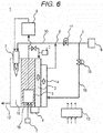
- FIG. 6 is a block diagram schematically showing one example of a general configuration of hydrogen generating apparatus 1 according to the fifth exemplary embodiment of the present invention.
- hydrogen generating apparatus 1 includes reformer 6, combustor 7, air feeder 9, combustion air channel 10, hydro-desulfurizer 3, cooler 14, contraction part 17, cooling channel 15, first valve 16, first temperature detector 19, and controller 13.
- Reformer 6 reforms a feed stock containing hydrocarbon to generate a hydrogen-containing gas.
- Combustor 7 combusts a combustion gas which is a feed stock or a hydrogen-containing gas, and air to heat reformer 6.
- Air feeder 9 feeds air to combustor 7.
- Combustion air channel 10 connects combustor 7 and air feeder 9.
- Hydro-desulfurizer 3 removes a sulfur component in a feed stock by hydrogenation reaction.
- Cooler 14 cools hydro-desulfurizer 3 by circulating air.
- Contraction part 17 is disposed in combustion air channel 10. Cooling channel 15 branches from combustion air channel 10 upstream contraction part 17, and conducts through cooler 14, and then joins combustion air channel 10 downstream contraction part 17.
- First valve 16 is disposed in cooling channel 15.
- first temperature detector 19 is disposed in the position where first temperature detector 19 can detect the temperature of reformer 6.
- first temperature detector 19 for example, a thermocouple or the like can be used.
- FIG. 7 is a flow chart showing one example of a method for operating hydrogen generating apparatus 1 according to the fifth exemplary embodiment of the present invention.
- FIG. 7 a method for operating hydrogen generating apparatus 1 according to the fifth exemplary embodiment of the present invention will be described.
- the operating method shown in FIG. 7 can be executed, for example, by controlling each part of hydrogen generating apparatus 1 by controller 13 according to the program stored in controller 13.
- step S502 As the operation of hydrogen generating apparatus 1 is started (S501), whether or not an ignition operation is conducted is determined (S502). When the determination result is NO (S502, NO), step S502 is executed again. When the determination result is YES (S502, YES), the opening of first valve 16 is increased (S503).
- step S506 is executed again.
- the determination result is YES (S506, YES)
- the opening of first valve 16 is decreased (S507).
- the first threshold is only required to be a temperature detected by first temperature detector 19 when the combustion condition of combustor 7 becomes stable, and is set at 300°C, for example, in the present exemplary embodiment.
- the timing of the determination is not necessarily limited to after end of the ignition operation, but may be after start of the ignition operation or after start of feeding reforming water, for example.
- An apparatus configuration of hydrogen generating apparatus 1 according to the sixth exemplary embodiment of the present invention can be similar to that of the first exemplary embodiment or the fifth exemplary embodiment except for the content of the control by controller 13, namely the method for operating hydrogen generating apparatus 1. Accordingly, a constituent common to that in FIG. 1 or FIG. 6 is denoted by the same reference mark and name, and detailed description thereof is omitted.
- controller 13 controls the feed amount of air from air feeder 9 to be increased before decreasing the opening of first valve 16.
- FIG. 8 is a flow chart showing one example of a method for operating hydrogen generating apparatus 1 according to the sixth exemplary embodiment of the present invention.
- FIG. 8 a method for operating hydrogen generating apparatus 1 according to the sixth exemplary embodiment will be described.
- the operating method shown in FIG. 8 can be executed, for example, by controlling each part of hydrogen generating apparatus 1 by controller 13 according to the program stored in controller 13.
- step S602 As the operation of hydrogen generating apparatus 1 is started (S601), whether or not an ignition operation is conducted is determined (S602). When the determination result is NO (S602, NO), step S602 is executed again. When the determination result is YES (S602, YES), the opening of first valve 16 is increased (S603).
- step S506 is executed again.
- the determination result is YES (S606, YES)
- the combustion air flow rate from air feeder 9 is increased (S607), and then the opening of first valve 16 is decreased (S608).
- the flow rate of combustion air fed from air feeder 9 decreases because the pressure loss of combustion air channel 10 increases.
- Decrease of a certain amount in combustion air flow rate with constant fuel results in decrease of a certain amount in air-fuel ratio which is a ratio between the combustion air and the fuel, and increase in concentration of carbon monoxide in the exhaust gas.
- the rate of increase in concentration of carbon monoxide in the exhaust gas is lower than the rate of increase in concentration of carbon monoxide in the exhaust gas when the air-fuel ratio decreases by a certain amount from the optimal value.
- the process before increase in the combustion air flow rate (S607) is not limited to the present exemplary embodiment, and the combustion air flow rate may be increased after start of feeding reforming water and combustion in combustor 7 becomes stable, for example, because it is only required that the combustion air flow rate is increased (S607) before the opening of first valve 16 is decreased (S608).
- An apparatus configuration of hydrogen generating apparatus 1 according to the seventh exemplary embodiment of the present invention can be similar to that of the first exemplary embodiment or the fifth exemplary embodiment except for the content of the control by controller 13, namely the method for operating hydrogen generating apparatus 1. Accordingly, a constituent common to that in FIG. 1 or FIG. 6 is denoted by the same reference mark and name, and detailed description thereof is omitted.
- controller 13 controls the feed amount of air from air feeder 9 to be decreased and the opening of first valve 16 to be decreased.
- FIG. 9 is a flow chart showing one example of a method for operating hydrogen generating apparatus 1 according to the seventh exemplary embodiment of the present invention.
- FIG. 9 a method for operating hydrogen generating apparatus 1 according to the seventh exemplary embodiment will be described.
- the operating method shown in FIG. 9 can be executed, for example, by controlling each part of hydrogen generating apparatus 1 by controller 13 according to the program stored in controller 13.
- step S702 As the operation of hydrogen generating apparatus 1 is started (S701), whether or not an ignition operation is conducted is determined (S702). When the determination result is NO (S702, NO), step S702 is executed again. When the determination result is YES (S702, YES), the opening of first valve 16 is increased (S703).
- step S706 is executed again.
- the determination result is YES (S706, YES)
- the combustion air flow rate from air feeder 9 is increased (S707), and then the combustion air flow rate from air feeder 9 is reduced and the opening of first valve 16 is decreased (S708).
- the amount of air fed from air feeder 9 decreases directly after decreasing the opening of first valve 16. Thereafter, control is exerted to feed a predetermined amount of air by increasing the manipulated variable of air feeder 9.
- an optimum air-fuel ratio is achieved directly after the opening of first valve 16 is decreased because the combustion air flow rate is increased before the opening of first valve 16 is decreased, however, after that time, the air-fuel ratio deviates as the combustion air flow rate is recovered (increased).
- the process before increasing the combustion air flow rate is not limited to the present exemplary embodiment, and for example, the combustion air flow rate may be increased after feed of reforming water is started and combustion in combustor 7 becomes stable.
- controller 13 of the first exemplary embodiment to the seventh exemplary embodiment may control the opening of first valve 16 to be increased at the time of connection when feed of a hydrogen-containing gas of hydrogen generating apparatus 1 to a hydrogen utilizing device (fuel cell 8) starts after completion of startup.
- hydrogen generating apparatus 1 of the exemplary embodiment includes reformer 6 for reforming a feed stock containing hydrocarbon to generate a hydrogen-containing gas, combustor 7 for heating reformer 6 by combusting a combustion gas which is a feed stock or a hydrogen-containing gas and air, air feeder 9 for feeding air to combustor 7, and combustion air channel 10 for connecting combustor 7 and air feeder 9.
- Hydrogen generating apparatus 1 also includes hydro-desulfurizer 3 for removing a sulfur component in a feed stock by hydrogenation reaction, cooler 14 for cooling hydro-desulfurizer 3 by circulating air, contraction part 17 disposed in combustion air channel 10, and cooling channel 15 that branches from combustion air channel 10 upstream contraction part 17, and conducts through cooler 14, and then joins combustion air channel 10 downstream contraction part 17. Further, hydrogen generating apparatus 1 includes first valve 16 disposed in cooling channel 15, and controller 13 configured to control an opening of first valve 16 to be increased at a predetermined timing.
- the combustion air is fed to combustor 7 via either one of first valve 16 and contraction part 17, and the total amount of the combustion air is invariable. Therefore, by increasing the opening of first valve 16 at a predetermined timing, the pressure loss of combustion air channel 10 decreases, and the pressure loss caused by the combustion air decreases.
- controller 13 may be configured to control the opening of first valve 16 to be increased in conducting an ignition operation of combustor 7.
- controller 13 may be configured to control the opening of first valve 16 to be increased in feeding reforming water to reformer 6 during startup.
- the combustion air is fed to combustor 7 via either one of first valve 16 and contraction part 17, and the total amount of the combustion air is invariable. Therefore, by increasing the opening of first valve 16 in feeding reforming water, the pressure loss of combustion air channel 10 decreases, and the pressure loss caused by the combustion air decreases.
- controller 13 may be configured to control the opening of first valve 16 to be decreased after a lapse of the first setting time from start or end of the ignition operation.
- the temperature of hydro-desulfurizer 3 becomes easy to increase, and it becomes possible to shorten the startup time of hydrogen generating apparatus 1 compared with the case where the opening of first valve 16 is not decreased.
- the time required for the combustion condition of combustor 7 to become stable from the point of time of starting the ignition operation or ending the ignition operation as the first setting time it becomes possible to shorten the startup time of hydrogen generating apparatus 1 without leading to the problem of increase in concentration of carbon monoxide in the exhaust gas or extinguishment.
- controller 13 may be configured to control the opening of first valve 16 to be decreased after a lapse of the second setting time from start of feeding reforming water.
- the temperature of hydro-desulfurizer 3 becomes easy to increase, and it becomes possible to shorten the startup time of hydrogen generating apparatus 1 compared with the case where the opening of first valve 16 is not decreased.
- the time required for the combustion condition of combustor 7 to become stable after start of feeding reforming water as the second setting time, it becomes possible to shorten the startup time of hydrogen generating apparatus 1 without leading to the problem of increase in concentration of carbon monoxide in the exhaust gas or extinguishment.
- the hydrogen generating apparatus may be configured such that first temperature detector 19 for detecting the temperature of reformer 6 is further provided, and controller 13 controls the opening of first valve 16 to be decreased when the temperature detected by first temperature detector 19 reaches the first threshold or higher.
- the temperature of hydro-desulfurizer 3 becomes easy to increase, and it becomes possible to shorten the startup time of hydrogen generating apparatus 1 compared with the case where the opening of first valve 16 is not decreased.
- the temperature detected by first temperature detector 19 when the combustion condition of combustor 7 becomes stable as the first threshold it becomes possible to shorten the startup time of hydrogen generating apparatus 1 without leading to the problem of increase in concentration of carbon monoxide in the exhaust gas or extinguishment.
- controller 13 may be configured to control the feed amount of air from air feeder 9 to be increased before decreasing the opening of first valve 16.
- the flow rate of combustion air fed from air feeder 9 decreases because the pressure loss of combustion air channel 10 increases.
- Decrease of a certain amount in the combustion air flow rate with constant fuel results in decrease of a certain amount in air-fuel ratio which is a ratio between the combustion air and the fuel, and increase in concentration of carbon monoxide in the exhaust gas.
- the rate of increase in concentration of carbon monoxide in the exhaust gas is lower than the rate of increase in concentration of carbon monoxide in the exhaust gas when the air-fuel ratio decreases by a certain amount from the optimal value
- controller 13 may be configured to control the feed amount of air from air feeder 9 to be decreased and to decrease the opening of first valve 16.
- the amount of air fed from air feeder 9 decreases directly after decreasing the opening of first valve 16. Thereafter, control is exerted to feed a predetermined amount of air by increasing the manipulated variable of air feeder 9.
- an optimum air-fuel ratio is achieved directly after decreasing the opening of first valve 16 because the combustion air flow rate is increased before decreasing the opening of first valve 16, and thereafter, the air-fuel ratio deviates as the combustion air flow rate is recovered (increased).
- controller 13 may control the opening of first valve 16 to be increased at the time of connection when feed of a hydrogen-containing gas of hydrogen generating apparatus 1 to a hydrogen utilizing device starts after completion of startup.
- FIG. 10 is a block diagram schematically showing one example of a general configuration of hydrogen generating apparatus 101 according to the eighth exemplary embodiment of the present invention.
- hydrogen generating apparatus 101 includes reformer 106, combustor 107, air feeder 109, combustion air channel 110, hydro-desulfurizer 103, cooler 114, contraction part 117, cooling channel 115, first valve 116, and controller 113.
- Reformer 106 reforms a feed stock containing hydrocarbon to generate a hydrogen-containing gas.
- Combustor 107 combusts a combustion gas which is a feed stock or a hydrogen-containing gas, and air to heat reformer 106.
- Air feeder 109 feeds air to combustor 107.
- Combustion air channel 110 connects combustor 107 and air feeder 109.
- Hydro-desulfurizer 103 removes a sulfur component in a feed stock by hydrogenation reaction.
- Cooler 114 cools hydro-desulfurizer 103 by circulating air.
- Contraction part 117 is disposed in combustion air channel 110.
- Cooling channel 115 branches from combustion air channel 110 upstream contraction part 117, and conducts through cooler 114, and then joins combustion air channel 110 downstream contraction part 117.
- First valve 116 is disposed in cooling channel 115. Controller 113 is configured to control an opening of first valve 116 to be increased at a predetermined timing during a stopping process in the present exemplary
- a gas containing an organic compound composed of at least carbon and hydrogen e.g., city gas containing methane as the main ingredient, natural gas, and LPG, kerosene, and alcohols such as methanol and ethanol
- the city gas means a gas supplied to each home or the like via piping from a gas company.
- the feed stock gas contains not only a sulfur compound derived from the feed stock gas, but also sulfides or sulfur compounds such as mercaptans added as an odorant for the purpose of detecting leakage.
- sulfides or sulfur compounds such as mercaptans added as an odorant for the purpose of detecting leakage.
- Concrete examples include tertiary-butylmercaptan (TBM), dimethyl sulfide (DMS), tetrahydrothiophene (THT), carbonyl sulfide (COS), and hydrogen sulfide.
- the feed stock is fed to feed stock flow controller 102, and after undergoing control of the flow rate by feed stock flow controller 102, the feed stock is mixed with part of the generated gas containing hydrogen as the main ingredient, and fed to hydro-desulfurizer 103 whose temperature is controlled within the range from 200°C to 300°C.
- the hydro-desulfurizing agent to be filled into hydro-desulfurizer 103 includes a hydrogen sulfide generating agent that generates hydrogen sulfide from a sulfur compound by hydrogenation reaction, and a hydrogen sulfide adsorbent that adsorbs hydrogen sulfide.
- a Co-Mo catalyst can be recited.
- the hydrogen sulfide adsorbent for example, zinc oxide can be recited.
- a catalyst having the functions of both the hydrogen sulfide generating agent and the hydrogen sulfide adsorbent may also be used.
- a catalyst for example, a Cu-Zn-Ni catalyst and a Cu-Zn-Fe catalyst can be recited.
- the hydro-desulfurizing agent to be filled into hydro-desulfurizer 3 is given merely for exemplification rather than for limiting the present invention.
- the desulfurized feed stock passes through piping 104, and is mixed with the water fed from water feeder 105, and after passing through a water evaporation part where the water is heated to turn into water vapor, the mixture is fed to reformer 106.
- Reformer 106 generates a hydrogen-containing gas composed of hydrogen, carbon dioxide, and carbon monoxide by steam reforming reaction using the feed stock and water vapor.
- the hydrogen-containing gas is fed to hydrogen utilizing device 108 via a carbon monoxide decreasing part that decreases carbon monoxide which is a poisoning substance for hydrogen utilizing device 108.
- a reforming catalyst is disposed inside reformer 106.
- the reforming catalyst allows progression of reforming reaction, and a hydrogen-containing gas can be generated from the feed stock and water.
- the heat required for the reforming reaction is supplied from combustor 107.
- the reforming catalyst generally, at least one selected from the group consisting of noble metal catalysts such as Pt, Ru, and Rh and Ni is preferably used. In the present example, a reforming catalyst containing Ru is used.
- Combustor 107 heats reformer 106 by combusting a hydrogen-containing gas discharged from hydrogen utilizing device 108 or by combusting the gas discharged from reformer 106.
- Combustor 107 may be supplied with other gases in addition to a hydrogen-containing gas as a fuel.
- the air required for combustion is fed to combustor 107 from air feeder 109 via combustion air channel 110.
- the combustion gas at high temperature generated by combustor 107 passes through heat exchange channel 111 and heats reformer 106 from 450°C to 650°C, and is then discharged from combustion exhaust gas route 112.
- Hydro-desulfurizer 103 is disposed in the vicinity of reformer 106 so that hydro-desulfurizer 103 is heated to a predetermined temperature ranging from 200°C to 300°C efficiently by the use of the heat of reformer 106. Since hydro-desulfurizer 103 and reformer 106 are integrally formed, it is possible to heat hydro-desulfurizer 103 efficiently by reformer 106, and to operate hydrogen generating apparatus 101 efficiently.
- Hydro-desulfurizer 103 may be disposed in the vicinity of the carbon monoxide decreasing part. Hydro-desulfurizer 103 is provided with cooler 114 in the position where heat exchange with hydro-desulfurizer 103 is possible. To cooler 114, cooling channel 115 that is branched from first branch part A in the midway of combustion air channel 110 and is connected to first joining part B is connected to allow passage of the air fed from air feeder 109 as a cooling medium.
- first valve 116 For adjusting the amount of air flowing in the channel of cooling channel 115, first valve 116 is disposed in cooling channel 115, and between first branch part A and first joining part B of combustion air channel 110, contraction part 117 capable of adjusting channel resistance is disposed. By providing channel resistance by contraction part 117, it becomes possible to feed part of the combustion air to cooler 114 as cooling air.
- first valve 116 a variable orifice or an on-off valve can be used.
- contraction part 117 an orifice that can serve as channel resistance, or a variable orifice can be used.
- Controller 113 controls the opening of first valve 116 according to the condition of hydrogen generating apparatus 101.
- Controller 113 is only required to have a control function, and includes a processing unit and a storage unit for storing a control program.
- a processing unit an MPU or a CPU can be exemplified.
- a storage unit memory can be exemplified.
- Controller 113 may be embodied by a single controller that conducts centralized control, or may be embodied by a plurality of controllers that conduct distributed control in cooperation with one another.
- FIG. 11 is a flow chart showing one example of a method for operating hydrogen generating apparatus 101 according to the eighth exemplary embodiment of the present invention.
- FIG. 11 a method for operating hydrogen generating apparatus 101 according to the eighth exemplary embodiment of the present invention will be described.
- the operating method shown in FIG. 11 can be executed, for example, by controlling each part of hydrogen generating apparatus 101 by controller 113 according to the program stored in controller 113.
- the stopping process as the opening of first valve 116 is increased, the resistance of combustion air channel 110 is decreased, and a predetermined amount of air required for cooling can be fed.
- the cooling air is fed to combustor 107 via either one of first valve 116 and contraction part 117. Since the total amount of the cooling air is invariable, resistance exerted on combustion air channel 110 where the total amount of the cooling air passes through is decreased by increasing the opening of first valve 116.
- the load exerted on air feeder 109 is alleviated, and a predetermined amount of air can be fed to hydro-desulfurizer 103 and combustor 107 in cooling while the manipulated variable of air feeder 109 does not reach the upper limit, and the stopping time of hydrogen generating apparatus 101 can be shortened.
- hydrogen generating apparatus 101 includes reformer 106 for reforming a feed stock containing hydrocarbon to generate a hydrogen-containing gas, combustor 107 for heating reformer 106 by combusting a combustion gas which is a feed stock or a hydrogen-containing gas and air, and air feeder 109 for feeding air to combustor 107.
- Hydrogen generating apparatus 101 also includes combustion air channel 110 for connecting combustor 107 and air feeder 109, hydro-desulfurizer 103 for removing a sulfur component in a feed stock by hydrogenation reaction, and cooler 114 for cooling hydro-desulfurizer 103 by circulating air.
- hydrogen generating apparatus 101 includes contraction part 117 disposed in combustion air channel 110, cooling channel 115 that branches from combustion air channel 110 upstream contraction part 117, and conducts through cooler 114, and then joins combustion air channel 110 downstream contraction part 117, and first valve 116 disposed in the cooling channel. Hydrogen generating apparatus 101 further includes controller 113 for controlling the opening of first valve 116 to be increased during a stopping process.
- Hydrogen generating apparatus 101 of the ninth exemplary embodiment is configured similarly to hydrogen generating apparatus 101 of the eighth exemplary embodiment.
- Controller 113 is configured to control an opening of first valve 116 to be increased after stopping feed of the combustion gas to combustor 107 during the stopping process.
- An apparatus configuration of hydrogen generating apparatus 101 according to the ninth exemplary embodiment of the present invention can be similar to that of the eighth exemplary embodiment except for the content of the control by controller 113, namely the method for operating hydrogen generating apparatus 101. Accordingly, a constituent common to that in FIG. 10 is denoted by the same reference mark and name, and detailed description thereof is omitted. Also in the ninth exemplary embodiment, modification similar to that of the eighth exemplary embodiment can be made.
- FIG. 12 is a flow chart showing one example of a method for operating hydrogen generating apparatus 101 according to the ninth exemplary embodiment of the present invention.
- the operating method shown in FIG. 12 can be executed, for example, by controlling each part of hydrogen generating apparatus 101 by controller 113 according to the program stored in controller 113.
- Hydrogen generating apparatus 101 of the tenth exemplary embodiment is hydrogen generating apparatus 101 of the ninth exemplary embodiment, and controller 113 is configured to control an opening of first valve 116 to be increased after stopping feed of the combustion gas to combustor 107, and after stopping feed of water for use in reforming a feed stock.
- An apparatus configuration of hydrogen generating apparatus 101 according to the tenth exemplary embodiment can be similar to that of the eighth exemplary embodiment except for the content of the control by controller 113, namely the method for operating hydrogen generating apparatus 101. Accordingly, a constituent common to that in FIG. 10 is denoted by the same reference mark and name, and detailed description thereof is omitted.
- FIG. 13 is a flow chart showing one example of a method for operating hydrogen generating apparatus 101 according to the tenth exemplary embodiment of the present invention.
- FIG. 13 a method for operating hydrogen generating apparatus 101 according to the tenth exemplary embodiment will be described.
- the operating method shown in FIG. 13 can be executed, for example, by controlling each part of hydrogen generating apparatus 101 by controller 113 according to the program stored in controller 113.
- hydrogen generating apparatus 101 shifts to the cooling step. That is, the manipulated variable of air feeder 109 is increased, and a predetermined large amount of air is fed to hydrogen generating apparatus 101.
- the manipulated variable of air feeder 109 is increased, and a predetermined large amount of air is fed to hydrogen generating apparatus 101.
- Hydrogen generating apparatus 101 of the eleventh exemplary embodiment is hydrogen generating apparatus 101 of the ninth exemplary embodiment or the tenth exemplary embodiment, and controller 113 is configured to control an opening of first valve 116 to be increased after extinguishment of combustor 107 is detected.
- An apparatus configuration of hydrogen generating apparatus 101 according to the eleventh exemplary embodiment can be similar to that of the eighth exemplary embodiment except for the content of the control by controller 113, namely the method for operating hydrogen generating apparatus 101. Accordingly, a constituent common to that in FIG. 10 is denoted by the same reference mark and name, and detailed description thereof is omitted.
- FIG. 14 is a flow chart showing one example of a method for operating hydrogen generating apparatus 101 according to the eleventh exemplary embodiment of the present invention.
- FIG. 14 a method for operating hydrogen generating apparatus 101 according to the tenth exemplary embodiment of the present invention will be described.
- the operating method shown in FIG. 14 can be executed, for example, by controlling each part of hydrogen generating apparatus 101 by controller 113 according to the program stored in controller 113.
- a predetermined amount of cooling air can be fed to hydro-desulfurizer 103 and combustor 107 from start of the cooling step, and hence the stopping time of hydrogen generating apparatus 101 can be shortened.
- a flame rod that detects a flame is used as the method for detecting extinguishment of combustor 107 in the present exemplary embodiment, a thermocouple or the like for detecting the temperature of combustor 107 may also be used.
- Fuel cell system 121 of the twelfth exemplary embodiment includes hydrogen generating apparatus 101 as described in any one of the eighth exemplary embodiment to the eleventh exemplary embodiment, and fuel cell 120 that generates power by using a hydrogen-containing gas fed from hydrogen generating apparatus 101.
- FIG. 15 is a schematic view showing one example of a general configuration of fuel cell system 121 according to the twelfth exemplary embodiment of the present invention.
- a configuration of hydrogen generating apparatus 101 can be similar to that of hydrogen generating apparatus 101 of the eighth exemplary embodiment and modified examples thereof. Accordingly, a constituent common between FIG. 15 and FIG. 10 is denoted by the same reference mark and name, and description thereof is omitted.
- Fuel cell 120 is a fuel cell that generates power by using a hydrogen-containing gas fed from hydrogen generating apparatus 101.
- Fuel cell 120 may be any kind of fuel cell, and for example, a polyelectrolyte fuel cell (PEFC), a solid oxide fuel cell, or a phosphate fuel cell can be used.
- PEFC polyelectrolyte fuel cell
- solid oxide fuel cell solid oxide fuel cell
- phosphate fuel cell a phosphate fuel cell
- Operation of fuel cell system 121 in the present exemplary embodiment can be similar to that of hydrogen generating apparatus 101 according to at least one of the eighth exemplary embodiment to the eleventh exemplary embodiment, and modified examples thereof. Therefore, detailed description thereof is omitted. With such a configuration, it is possible to feed a predetermined amount of cooling air to hydro-desulfurizer 103 and combustor 107 at the time of stopping, so that it is possible to shorten the stopping time of fuel cell system 121.
- hydrogen generating apparatus 101 of the exemplary embodiment includes reformer 106 for reforming a feed stock containing hydrocarbon to generate a hydrogen-containing gas, combustor 107 for heating reformer 106 by combusting a combustion gas which is a feed stock or a hydrogen-containing gas and air, and air feeder 109 for feeding air to combustor 107.
- Hydrogen generating apparatus 101 also includes combustion air channel 110 for connecting combustor 107 and air feeder 109, hydro-desulfurizer 103 for removing a sulfur component in a feed stock by hydrogenation reaction, and cooler 114 for cooling hydro-desulfurizer 103 by circulating air.
- Hydrogen generating apparatus 101 also includes contraction part 117 disposed in combustion air channel 110, cooling channel 115 that branches from combustion air channel 110 upstream contraction part 117, and conducts through cooler 114, and then joins combustion air channel 110 downstream contraction part 117, first valve 116 disposed in the cooling channel, and controller 113 for controlling an opening of first valve 116 to be increased at a predetermined timing, for example, during a stopping process.
- Controller 113 of hydrogen generating apparatus 101 may be configured to control the opening of first valve 116 to be increased after stopping feed of the combustion gas to combustor 107 during the stopping process.
- Controller 113 of hydrogen generating apparatus 101 may be configured to control the opening of first valve 116 to be increased after stopping feed of the combustion gas to combustor 107, and after stopping feed of water for use in reforming a feed stock.
- Controller 113 may be configured to control the opening of first valve 116 to be increased after extinguishment of combustor 107 is detected.
- Fuel cell system 121 of the exemplary embodiment includes hydrogen generating apparatus 101, and fuel cell 120 that generates power by using a hydrogen-containing gas fed from hydrogen generating apparatus 101.
- hydrogen generating apparatus 101 of the exemplary embodiment includes reformer 106 for reforming a feed stock containing hydrocarbon to generate a hydrogen-containing gas, combustor 107 for heating reformer 106 by combusting a combustion gas which is a feed stock or a hydrogen-containing gas and air, and air feeder 109 for feeding air to combustor 107.
- Hydrogen generating apparatus 101 also includes combustion air channel 110 for connecting combustor 107 and air feeder 109, hydro-desulfurizer 103 for removing a sulfur component in a feed stock by hydrogenation reaction, and cooler 114 for cooling hydro-desulfurizer 103 by circulating air.
- hydrogen generating apparatus 101 includes contraction part 117 disposed in combustion air channel 110, and cooling channel 115 that branches from combustion air channel 110 upstream contraction part 117, and conducts through cooler 114, and then joins combustion air channel 110 downstream contraction part 117. Hydrogen generating apparatus 101 also includes first valve 116 disposed in the cooling channel. It is described to provide the operating method of such hydrogen generating apparatus 101 with the step of increasing the opening of first valve 116 during the stopping process. This method can shorten the stopping time.
- the method may also increase the opening of first valve 116 after stopping feed of the combustion gas to combustor 107 during the stopping process.
- the method may also increase the opening of first valve 116 after stopping feed of the combustion gas to combustor 107, and after stopping feed of water for use in reforming a feed stock.
- the method may also increase the opening of first valve 116 after extinguishment of combustor 107 is detected.
- the present invention is useful as a hydrogen generating apparatus that generates hydrogen by reacting a hydrocarbonic feed stock with water, more specifically a hydrogen generating apparatus equipped with a hydro-desulfurizer for removing a sulfur compound which is contained in a feed stock and harmful to the hydrogen generating apparatus, by hydrogenation reaction, and a method for operating the same.
Landscapes
- Chemical & Material Sciences (AREA)
- Chemical Kinetics & Catalysis (AREA)
- Engineering & Computer Science (AREA)
- Organic Chemistry (AREA)
- General Chemical & Material Sciences (AREA)
- Sustainable Energy (AREA)
- Sustainable Development (AREA)
- Electrochemistry (AREA)
- Life Sciences & Earth Sciences (AREA)
- Health & Medical Sciences (AREA)
- General Health & Medical Sciences (AREA)
- Combustion & Propulsion (AREA)
- Inorganic Chemistry (AREA)
- Manufacturing & Machinery (AREA)
- Hydrogen, Water And Hydrids (AREA)
- Fuel Cell (AREA)
Abstract
Description
- The present invention relates to a hydrogen generating apparatus that generates hydrogen by reacting a hydrocarbonic feed stock with water. More specifically, the present invention relates to a hydrogen generating apparatus equipped with a hydro-desulfurizer for removing a sulfur compound which is contained in a feed stock and harmful to the hydrogen generating apparatus, by hydrogenation reaction, and a method for operating the same.
- A fuel cell system is usually equipped with a hydrogen generating apparatus because a hydrogen gas used as a fuel for power generation is not ready as a common infrastructure. In a hydrogen generating apparatus, steam reforming reaction is generally used.
- The steam reforming reaction generates a hydrogen-containing gas containing hydrogen as the main ingredient by reacting city gas which is a feed stock with water vapor by using a Ni or Ru reforming catalyst at a high temperature ranging from about 600°C to 700°C. As a method for obtaining thermal energy required for the steam reforming reaction, a method of combusting a fuel offgas from a fuel cell with a combustor is commonly conducted.
- The feed stock fed to the hydrogen generating apparatus contains a sulfur compound. Concretely, city gas containing methane as the main ingredient and LP gas contain sulfur compounds such as sulfides or mercaptans added as an odorant for detecting leakage, in addition to sulfur components derived from the feed stock. Sulfur contained in these sulfur compounds, even at very low concentration, is known to advance deterioration in activity of Ni and Ru reforming catalysts that are often used in the steam reforming reaction.
- Therefore, for a feed stock like city gas and LP gas, an appropriate desulfurization treatment is conducted before the feed stock is fed to a hydrogen generating apparatus. As a desulfurization treatment method, the following two methods are currently employed: an adsorbent desulfurizing method and a hydrodesulfurization method.
- The adsorbent desulfurizing method removes sulfur compounds by passing a feed stock through a desulfurizer filled with an adsorbent capable of adsorbing sulfur compounds at normal temperature, and has a merit of very simple handling. However, its small adsorption capacity raises the frequency of replacement of the desulfurizer when the sulfur compound concentration in the feed stock is high, leading to the problem of increase in the total cost.
- On the other hand, the hydrodesulfurization method converts a sulfur compound to hydrogen sulfide that is easy to be adsorbed, by adding hydrogen to a feed stock to cause hydrogenation reaction, and removes the generated hydrogen sulfide by adsorption to an adsorbent, and hence has a merit of large adsorption capacity. However, the hydrodesulfurization method has a problem that the desulfurizer must be kept at appropriate temperatures ranging from about 200°C which is the lowest temperature to about 300°C which is the highest temperature or less to allow hydrogenation reaction and adsorption.
- To be more specific, when the temperature of the hydro-desulfurizer is lower than the lowest temperature, the adsorption capacity significantly decreases, and conversely, when the temperature is higher than the highest temperature, the hydro-desulfurizing agent is thermally degraded, and loses the desulfurizing ability.
- In light of this, there is a proposal of providing a heat exchanger for cooling inside or on the surface of a hydro-desulfurizer, and circulating air which is a cooling medium in the heat exchanger for cooling, thereby cooling the hydro-desulfurizer so that the hydro-desulfurizer is kept at an appropriate temperature (see, for example, PTL 1).
- However, in the hydrogen generating apparatus disclosed in
PTL 1, pressure fluctuation occurs in the combustion space and the combustion air channel because the combustion condition is unstable directly after ignition of the combustor. At this time, since controllability of the combustion air flow rate is impaired, excess and deficiency of combustion air feed, or oscillation of combustion flame (oscillated combustion) occurs, which can lead to the problem of increase in concentration of carbon monoxide in the exhaust gas or extinguishment. - PTL 1: Unexamined
Japanese Patent Publication No. 10-214632 - The present invention has been made in consideration of the aforementioned problems, and provides a hydrogen generating apparatus capable of checking unstable combustion in a combustor, and a method for operating the same.
- A hydrogen generating apparatus of the present invention includes a reformer for reforming a feed stock containing hydrocarbon to generate a hydrogen-containing gas; a combustor for heating the reformer by combusting a combustion gas which is a feed stock or a hydrogen-containing gas and air; an air feeder for feeding air to the combustor; and a combustion air channel for connecting the combustor and the air feeder. The hydrogen generating apparatus also includes a hydro-desulfurizer for removing a sulfur component in a feed stock by hydrogenation reaction; a cooler for cooling the hydro-desulfurizer by circulating air; a contraction part disposed in the combustion air channel; and a cooling channel that branches from the combustion air channel upstream the contraction part, and conducts through the cooler, and then joins the combustion air channel downstream the contraction part. The hydrogen generating apparatus further includes a first valve disposed in the cooling channel; and a controller configured to control an opening of the first valve to be increased at a predetermined timing.
- With such a configuration, it is possible to check unstable combustion in the combustor, and to operate the hydrogen generating apparatus stably.
- A method for operating a hydrogen generating apparatus of the present invention is a method for operating a hydrogen generating apparatus including: a reformer for reforming a feed stock containing hydrocarbon to generate a hydrogen-containing gas; a combustor for heating the reformer by combusting a combustion gas which is a feed stock or a hydrogen-containing gas and air; an air feeder for feeding air to the combustor; a combustion air channel for connecting the combustor and the air feeder; a hydro-desulfurizer for removing a sulfur component in a feed stock by hydrogenation reaction; a cooler for cooling the hydro-desulfurizer by circulating air; a contraction part disposed in the combustion air channel; a cooling channel that branches from the combustion air channel upstream the contraction part, and conducts through the cooler, and then joins the combustion air channel downstream the contraction part; and a first valve disposed in the cooling channel. The method includes the step of increasing an opening of the first valve at a predetermined timing.
- With such a method, it is possible to check unstable combustion in the combustor, and to operate the hydrogen generating apparatus stably.
-
-
FIG. 1 is a block diagram schematically showing one example of a general configuration of a hydrogen generating apparatus according to the first exemplary embodiment of the present invention. -
FIG. 2 is a flow chart showing one example of a method for operating the hydrogen generating apparatus according to a first exemplary embodiment of the present invention. -
FIG. 3 is a flow chart showing one example of a method for operating a hydrogen generating apparatus according to a second exemplary embodiment of the present invention. -
FIG. 4 is a flow chart showing one example of a method for operating a hydrogen generating apparatus according to a third exemplary embodiment of the present invention. -
FIG. 5 is a flow chart showing one example of a method for operating a hydrogen generating apparatus according to a fourth exemplary embodiment of the present invention. -
FIG. 6 is a block diagram schematically showing one example of a general configuration of a hydrogen generating apparatus according to a fifth exemplary embodiment of the present invention. -
FIG. 7 is a flow chart showing one example of a method for operating the hydrogen generating apparatus according to the fifth exemplary embodiment of the present invention. -
FIG. 8 is a flow chart showing one example of a method for operating a hydrogen generating apparatus according to a sixth exemplary embodiment of the present invention. -
FIG. 9 is a flow chart showing one example of a method for operating a hydrogen generating apparatus according to a seventh exemplary embodiment of the present invention. -
FIG. 10 is a block diagram schematically showing one example of a general configuration of a hydrogen generating apparatus according to an eighth exemplary embodiment of the present invention. -
FIG. 11 is a flow chart showing one example of a method for operating the hydrogen generating apparatus according to the eighth exemplary embodiment of the present invention. -
FIG. 12 is a flow chart showing one example of a method for operating a hydrogen generating apparatus according to a ninth exemplary embodiment of the present invention. -
FIG. 13 is a flow chart showing one example of a method for operating a hydrogen generating apparatus according to a tenth exemplary embodiment of the present invention. -
FIG. 14 is a flow chart showing one example of a method for operating a hydrogen generating apparatus according to an eleventh exemplary embodiment of the present invention. -
FIG. 15 is a schematic view showing one example of a general configuration offuel cell system 121 according to a twelfth exemplary embodiment of the present invention. - Hereinafter, each exemplary embodiment of the hydrogen generating apparatus according to the present invention will be described with reference to the drawings. Numerical values, shapes, materials, constituents, disposed positions and connecting forms of constituents, steps, sequences of steps and so on shown in each exemplary embodiment are merely examples.
- Among the constituents in the following exemplary embodiments, a constituent that is not described in an independent claim showing the highest concept of the present invention is described as an optional constituent constituting a more desirable form. For the constituent denoted by the same reference mark in different drawings, overlapping description is sometimes omitted.
-
FIG. 1 is a block diagram schematically showing one example of a general configuration ofhydrogen generating apparatus 1 according to the first exemplary embodiment of the present invention. - As illustrated in
FIG. 1 ,hydrogen generating apparatus 1 according to the first exemplary embodiment of the present invention includesreformer 6, combustor 7,air feeder 9,combustion air channel 10, hydro-desulfurizer 3,cooler 14,contraction part 17,cooling channel 15,first valve 16, andcontroller 13. -
Reformer 6 reforms a feed stock containing hydrocarbon to generate a hydrogen-containing gas. Combustor 7 combusts a combustion gas which is a feed stock or a hydrogen-containing gas, and air toheat reformer 6.Air feeder 9 feeds air to combustor 7.Combustion air channel 10 connects combustor 7 andair feeder 9. Hydro-desulfurizer 3 removes a sulfur component in a feed stock by hydrogenation reaction. Cooler 14 cools hydro-desulfurizer 3 by circulating air.Contraction part 17 is disposed incombustion air channel 10.Cooling channel 15 branches fromcombustion air channel 10upstream contraction part 17, and conducts throughcooler 14, and then joinscombustion air channel 10downstream contraction part 17.First valve 16 is disposed incooling channel 15.Controller 13 is configured to control an opening offirst valve 16 to be increased at a predetermined timing. In the present exemplary embodiment,controller 13 is configured to control the opening offirst valve 16 to be increased in conducting an ignition operation of combustor 7. - Here, as the feed stock, those selected from a gas containing an organic compound composed of at least carbon and hydrogen, among city gas containing methane as the main ingredient, natural gas, LPG and so on, kerosene, and alcohols such as methanol and ethanol can be used. The city gas means a gas supplied to each home or the like via piping from a gas company.
- The feed stock contains not only a sulfur compound derived from the feed stock, but also sulfides or sulfur compounds such as mercaptans added as an odorant for the purpose of detecting leakage. Concrete examples include tertiary-butylmercaptan (TBM), dimethyl sulfide (DMS), tetrahydrothiophene (THT), carbonyl sulfide (COS), and hydrogen sulfide.
- The feed stock is fed to feed
stock flow controller 2, and after undergoing control of the flow rate by feedstock flow controller 2, the feed stock is mixed with part of the generated gas containing hydrogen as the main ingredient, and fed to hydro-desulfurizer 3 whose temperature is controlled within the range from 200°C to 300°C. - The hydro-desulfurizing agent to be filled into hydro-
desulfurizer 3 includes a hydrogen sulfide generating agent that generates hydrogen sulfide from a sulfur compound by hydrogenation reaction, and a hydrogen sulfide adsorbent that adsorbs hydrogen sulfide. - Here, as the hydrogen sulfide generating agent, for example, a Co-Mo catalyst can be recited. As the hydrogen sulfide adsorbent, for example, zinc oxide can be recited. A catalyst having the functions of both the hydrogen sulfide generating agent and the hydrogen sulfide adsorbent may also be used. As such a catalyst, for example, a Cu-Zn-Ni catalyst and a Cu-Zn-Fe catalyst can be recited. The hydro-desulfurizing agent to be filled into hydro-
desulfurizer 3 is given merely for exemplification rather than for limiting the present invention. - The feed stock desulfurized in hydro-
desulfurizer 3 passes through piping 4, and is mixed with the water fed fromwater feeder 5, and after passing through a water evaporation part where the water is heated to turn into water vapor, the mixture is fed toreformer 6. -
Reformer 6 generates a hydrogen-containing gas composed of hydrogen, carbon dioxide, and carbon monoxide by steam reforming reaction using the feed stock and water vapor. The hydrogen-containing gas is fed tofuel cell 8 via a carbon monoxide decreasing part that decreases carbon monoxide which is a poisoning substance forfuel cell 8. - Inside
reformer 6, a reforming catalyst is disposed. The reforming catalyst allows progression of reforming reaction, and a hydrogen-containing gas can be generated from the feed stock and water. The heat required for the reforming reaction is supplied from combustor 7. - As the reforming catalyst, generally, at least one selected from the group consisting of noble metal catalysts such as Pt, Ru, and Rh and Ni is preferably used. In the present example, a reforming catalyst containing Ru is used.
- Combustor 7
heats reformer 6 by combusting a hydrogen-containing gas discharged fromfuel cell 8 or by combusting the gas discharged fromreformer 6. Combustor 7 may be supplied with other gases in addition to a hydrogen-containing gas as a fuel. - The air required for combustion is fed to combustor 7 from
air feeder 9 viacombustion air channel 10. The combustion gas at high temperature generated by combustor 7 passes throughheat exchange channel 11 andheats reformer 6 from 450°C to 650°C, and is then discharged from combustionexhaust gas route 12. - Hydro-
desulfurizer 3 is disposed in the vicinity ofreformer 6 so that hydro-desulfurizer 3 is heated to a predetermined temperature ranging from 200°C to 300°C efficiently by the use of the heat ofreformer 6. Hhydro-desulfurizer 3 may be disposed in the vicinity of the carbon monoxide decreasing part. Further, cooler 14 is disposed in the position where heat exchange with hydro-desulfurizer 3 is possible. - To cooler 14, cooling
channel 15 that is branched from first branch part A in the midway ofcombustion air channel 10 and is connected to first joining part B is connected to allow passage of the air fed fromair feeder 9 as a cooling medium. - For adjusting the amount of air flowing in the channel of cooling
channel 15,first valve 16 is disposed in coolingchannel 15upstream cooler 14. Between first branch part A and first joining part B ofcombustion air channel 10,contraction part 17 capable of adjusting channel resistance ofcombustion air channel 10 is disposed. - By providing channel resistance by
contraction part 17, it becomes possible to feed part (predetermined percentage) of the combustion air to cooler 14 as cooling air. Here, asfirst valve 16, a variable orifice or an on-off valve can be used. Further, ascontraction part 17, an orifice that can serve as channel resistance, or a variable orifice can be used. -
Controller 13 controls the opening offirst valve 16 according to the condition ofhydrogen generating apparatus 1.Controller 13 is only required to have a control function, and includes a processing unit and a storage unit for storing a control program. - As the processing unit, an MPU or a CPU can be exemplified. As the storage unit, memory can be exemplified.
Controller 13 may be embodied by a single controller that conducts centralized control, or may be embodied by a plurality of controllers that conduct distributed control in cooperation with one another. -
FIG. 2 is a flow chart showing one example of a method for operatinghydrogen generating apparatus 1 according to the first exemplary embodiment of the present invention. - Hereinafter, referring to
FIG. 2 , a method for operatinghydrogen generating apparatus 1 according to the first exemplary embodiment will be described. The operating method shown inFIG. 2 can be executed, for example, by controlling each part ofhydrogen generating apparatus 1 bycontroller 13 according to the program stored incontroller 13. - As the operation of
hydrogen generating apparatus 1 is started (S101), whether or not an ignition operation is conducted is determined (S102). When the determination result is NO (S102, NO), step S102 is executed again. On the other hand, when the determination result is YES (S102, YES), the opening offirst valve 16 is increased (S103). - Since the combustion condition is unstable directly after ignition of combustor 7, pressure fluctuation occurs in the combustion space and
combustion air channel 10. Since controllability of the combustion air flow rate is impaired at this time, excess and deficiency of combustion air feed, or oscillation of combustion flame (oscillated combustion) occurs, which can lead to the problem of increase in concentration of carbon monoxide in the exhaust gas or extinguishment. - Here, by increasing the opening of
first valve 16 at the time of ignition, pressure loss ofcombustion air channel 10 is diminished, and pressure fluctuation occurring at the time of ignition is alleviated, and unstable combustion can be checked. - That is, while combustion air is fed to combustor 7 via either one of
first valve 16 andcontraction part 17, the pressure loss caused by the combustion air decreases by increasing the opening offirst valve 16 because the total amount of the combustion air is invariable. - As described above, according to the present exemplary embodiment, since the influence of the pressure fluctuation occurring at the time of ignition on the combustion air is alleviated, unstable combustion is checked.
- Next, the second exemplary embodiment of the present invention will be described.
- An apparatus configuration of
hydrogen generating apparatus 1 according to the second exemplary embodiment of the present invention can be similar to that described in the first exemplary embodiment except for the content of the control bycontroller 13, namely the method for operatinghydrogen generating apparatus 1. Accordingly, a constituent common to that inFIG. 1 is denoted by the same reference mark and name, and detailed description thereof is omitted. - In
hydrogen generating apparatus 1 of the second exemplary embodiment,controller 13 controls the opening offirst valve 16 to be increased when reforming water is fed toreformer 6 during startup. - Also in the second exemplary embodiment, modification similar to that in the first exemplary embodiment is possible.
-
FIG. 3 is a flow chart showing one example of a method for operatinghydrogen generating apparatus 1 according to the second exemplary embodiment of the present invention. - Hereinafter, referring to
FIG. 3 , a method for operatinghydrogen generating apparatus 1 according to the second exemplary embodiment will be described. The operating method shown inFIG. 3 can be executed, for example, by controlling each part ofhydrogen generating apparatus 1 bycontroller 13 according to the program stored incontroller 13. - As the operation of
hydrogen generating apparatus 1 is started (S201), whether or not reforming water is fed is determined (S202). When the determination result is NO (S202, NO), step S202 is executed again. When the determination result is YES (S202, YES), the opening offirst valve 16 is increased (S203). - In feeding reforming water to
reformer 6, first the reforming water is heated in the water evaporation part disposed in the previous stage ofreformer 6, and the state changes from water to water vapor. Since the volume of the fluid fed toreformer 6 rapidly increases with the change of state, the feed stock having been fed intoreformer 6 is pushed out. - While the pushed out feed stock is combusted as a fuel by combustor 7, the rapid increase in the fuel flow rate makes the combustion condition by combustor 7 unstable, and pressure fluctuation occurs in the combustion space and
combustion air channel 10. Since controllability of the combustion air flow rate is impaired at this time, excess and deficiency of combustion air feed, or oscillation of combustion flame (oscillated combustion) occurs, which can lead to the problem of increase in concentration of carbon monoxide in the exhaust gas or extinguishment. - By increasing the opening of
first valve 16 in feeding reforming water, pressure loss ofcombustion air channel 10 decreases, and pressure fluctuation occurring in feeding reforming water is alleviated, and unstable combustion can be checked. - That is, while combustion air is fed to combustor 7 via either one of
first valve 16 andcontraction part 17, the pressure loss caused by the combustion air decreases by increasing the opening offirst valve 16 because the total amount of the combustion air is invariable. - As described above, according to the present exemplary embodiment, since the influence of the pressure fluctuation occurring in feeding reforming water on the combustion air is alleviated, unstable combustion is checked.
- Next, the third exemplary embodiment of the present invention will be described.
- An apparatus configuration of
hydrogen generating apparatus 1 according to the third exemplary embodiment of the present invention can be similar to that of the first exemplary embodiment except for the content of the control bycontroller 13, namely the method for operatinghydrogen generating apparatus 1. Accordingly, a constituent common to that inFIG. 1 is denoted by the same reference mark and name, and detailed description thereof is omitted. - In
hydrogen generating apparatus 1 of the third exemplary embodiment of the present invention,controller 13 controls the opening offirst valve 16 to be decreased after a lapse of a first setting time from start or end of the ignition operation. -
FIG. 4 is a flow chart showing one example of a method for operatinghydrogen generating apparatus 1 according to the third exemplary embodiment of the present invention. - Hereinafter, referring to
FIG. 4 , a method for operatinghydrogen generating apparatus 1 according to the third exemplary embodiment will be described. The operating method shown inFIG. 4 can be executed, for example, by controlling each part ofhydrogen generating apparatus 1 bycontroller 13 according to the program stored incontroller 13. - As the operation of
hydrogen generating apparatus 1 is started (S301), whether or not an ignition operation is conducted is determined (S302). When the determination result is NO (S302, NO), step S302 is executed again. When the determination result is YES (S302, YES), the opening offirst valve 16 is increased (S303). - Then, an ignition operation is conducted (S304), and after end of the ignition operation (S305), whether or not the first setting time has lapsed is determined (S306). When the determination result is NO (S306, NO), step S306 is executed again. When the determination result is YES (S306, YES), the opening of
first valve 16 is decreased (S307). - When the opening of
first valve 16 is increased, more air is fed to cooler 14, so that hydro-desulfurizer 3 is more cooled and the temperature rise of hydro-desulfurizer 3 is decelerated, and the startup time ofhydrogen generating apparatus 1 is extended. - By decreasing the opening of
first valve 16 at the point of time when the combustion condition of combustor 7 becomes stable after end of the ignition operation, the flow rate of air fed to cooler 14 is decreased, and cooling of hydro-desulfurizer 3 is alleviated. - Therefore, the temperature of hydro-
desulfurizer 3 becomes easy to increase, and it becomes possible to shorten the startup time ofhydrogen generating apparatus 1. - In addition, by setting the time required for the combustion condition of combustor 7 to become stable after end of the ignition operation as the first setting time, it becomes possible to shorten the startup time of
hydrogen generating apparatus 1 without leading to the problem of increase in concentration of carbon monoxide in the exhaust gas or extinguishment. - The first setting time may be a time from start of the ignition operation without limited to the time after end of the ignition operation. The first setting time is only required to be a time required for the combustion condition of combustor 7 to become stable, and is set at 1 minute, for example, in the present exemplary embodiment.
- Next, the fourth exemplary embodiment of the present invention will be described.
- An apparatus configuration of
hydrogen generating apparatus 1 according to the fourth exemplary embodiment of the present invention can be similar to that of the first exemplary embodiment except for the content of the control bycontroller 13, namely the method for operatinghydrogen generating apparatus 1. Accordingly, a constituent common to that inFIG. 1 is denoted by the same reference mark and name, and detailed description thereof is omitted. - In
hydrogen generating apparatus 1 of the fourth exemplary embodiment of the present invention,controller 13 controls the opening offirst valve 16 to be decreased after a lapse of a second setting time from start of feeding reforming water. -
FIG. 5 is a flow chart showing one example of a method for operatinghydrogen generating apparatus 1 according to the fourth exemplary embodiment of the present invention. - Hereinafter, referring to
FIG. 5 , a method for operatinghydrogen generating apparatus 1 according to the fourth exemplary embodiment of the present invention will be described. The operating method shown inFIG. 5 can be executed, for example, by controlling each part ofhydrogen generating apparatus 1 bycontroller 13 according to the program stored incontroller 13. - As the operation of
hydrogen generating apparatus 1 is started (S401), whether or not reforming water is fed is determined (S402). When the determination result is NO (S402, NO), step S402 is executed again. When the determination result is YES (S402, YES), the opening offirst valve 16 is increased (S403). - Thereafter, feed of reforming water is started (S404), and then whether or not the second setting time has lapsed is determined (S405). When the determination result is NO (S405, NO), step S405 is executed again. When the determination result is YES (S405, YES), the opening of
first valve 16 is decreased (S406). - When the opening of
first valve 16 is increased, more air is fed to cooler 14, so that hydro-desulfurizer 3 is more cooled and the temperature rise of hydro-desulfurizer 3 is decelerated, and the startup time ofhydrogen generating apparatus 1 is extended. - By decreasing the opening of
first valve 16 at the point of time when the combustion condition of combustor 7 becomes stable after start of feeding reforming water, the flow rate of air fed to cooler 14 is decreased, and cooling of hydro-desulfurizer 3 is alleviated. - Therefore, the temperature of hydro-
desulfurizer 3 becomes easy to increase, and it becomes possible to shorten the startup time ofhydrogen generating apparatus 1. - By setting the time required for the combustion condition of combustor 7 to become stable after start of feeding reforming water as the second setting time, it becomes possible to shorten the startup time of
hydrogen generating apparatus 1 without leading to the problem of increase in concentration of carbon monoxide in the exhaust gas or extinguishment. - The second setting time is only required to be a time required for the combustion condition of combustor 7 to become stable after start of feeding reforming water, and is set at 5 minutes, for example, in the present exemplary embodiment.
- Next, the fifth exemplary embodiment of the present invention will be described.
-
FIG. 6 is a block diagram schematically showing one example of a general configuration ofhydrogen generating apparatus 1 according to the fifth exemplary embodiment of the present invention. - As illustrated in
FIG. 6 ,hydrogen generating apparatus 1 according to the fifth exemplary embodiment of the present invention includesreformer 6, combustor 7,air feeder 9,combustion air channel 10, hydro-desulfurizer 3, cooler 14,contraction part 17, coolingchannel 15,first valve 16,first temperature detector 19, andcontroller 13. -
Reformer 6 reforms a feed stock containing hydrocarbon to generate a hydrogen-containing gas. Combustor 7 combusts a combustion gas which is a feed stock or a hydrogen-containing gas, and air to heatreformer 6.Air feeder 9 feeds air to combustor 7.Combustion air channel 10 connects combustor 7 andair feeder 9. Hydro-desulfurizer 3 removes a sulfur component in a feed stock by hydrogenation reaction.Cooler 14 cools hydro-desulfurizer 3 by circulating air.Contraction part 17 is disposed incombustion air channel 10. Coolingchannel 15 branches fromcombustion air channel 10upstream contraction part 17, and conducts through cooler 14, and then joinscombustion air channel 10downstream contraction part 17.First valve 16 is disposed in coolingchannel 15.First temperature detector 19 detects the temperature ofreformer 6.Controller 13 is configured to control an opening offirst valve 16 to be increased in conducting the ignition operation of combustor 7 and control the opening offirst valve 16 to be decreased when the temperature detected byfirst temperature detector 19 reaches the first threshold or higher during startup. - Here,
first temperature detector 19 is disposed in the position wherefirst temperature detector 19 can detect the temperature ofreformer 6. Asfirst temperature detector 19, for example, a thermocouple or the like can be used. -
FIG. 7 is a flow chart showing one example of a method for operatinghydrogen generating apparatus 1 according to the fifth exemplary embodiment of the present invention. - Hereinafter, referring to
FIG. 7 , a method for operatinghydrogen generating apparatus 1 according to the fifth exemplary embodiment of the present invention will be described. The operating method shown inFIG. 7 can be executed, for example, by controlling each part ofhydrogen generating apparatus 1 bycontroller 13 according to the program stored incontroller 13. - As the operation of
hydrogen generating apparatus 1 is started (S501), whether or not an ignition operation is conducted is determined (S502). When the determination result is NO (S502, NO), step S502 is executed again. When the determination result is YES (S502, YES), the opening offirst valve 16 is increased (S503). - Then, an ignition operation is conducted (S504), and after end of the ignition operation (S505), whether or not the temperature detected by
first temperature detector 19 is the first threshold or higher is determined (S506). When the determination result is NO (S506, NO), step S506 is executed again. When the determination result is YES (S506, YES), the opening offirst valve 16 is decreased (S507). - When the opening of
first valve 16 is increased, more air is fed to cooler 14, so that hydro-desulfurizer 3 is more cooled and the temperature rise of hydro-desulfurizer 3 is decelerated, and the startup time ofhydrogen generating apparatus 1 is extended. - By decreasing the opening of
first valve 16 at the point of time when the combustion condition of combustor 7 becomes stable, the flow rate of air fed to cooler 14 is decreased, and cooling of hydro-desulfurizer 3 is alleviated. Therefore, the temperature of hydro-desulfurizer 3 becomes easy to increase, and it becomes possible to shorten the startup time ofhydrogen generating apparatus 1. - By setting the temperature detected by
first temperature detector 19 when the combustion condition of combustor 7 becomes stable as the first threshold, it becomes possible to shorten the startup time of thehydrogen generating apparatus 1 without leading to the problem of increase in concentration of carbon monoxide in the exhaust gas or extinguishment. - The first threshold is only required to be a temperature detected by
first temperature detector 19 when the combustion condition of combustor 7 becomes stable, and is set at 300°C, for example, in the present exemplary embodiment. - While whether or not the temperature detected by
first temperature detector 19 after end of the ignition operation is the first threshold or higher is determined in the present exemplary embodiment, the timing of the determination is not necessarily limited to after end of the ignition operation, but may be after start of the ignition operation or after start of feeding reforming water, for example. - Next, the sixth exemplary embodiment of the present invention will be described.
- An apparatus configuration of
hydrogen generating apparatus 1 according to the sixth exemplary embodiment of the present invention can be similar to that of the first exemplary embodiment or the fifth exemplary embodiment except for the content of the control bycontroller 13, namely the method for operatinghydrogen generating apparatus 1. Accordingly, a constituent common to that inFIG. 1 orFIG. 6 is denoted by the same reference mark and name, and detailed description thereof is omitted. - In
hydrogen generating apparatus 1 of the sixth exemplary embodiment,controller 13 controls the feed amount of air fromair feeder 9 to be increased before decreasing the opening offirst valve 16. -
FIG. 8 is a flow chart showing one example of a method for operatinghydrogen generating apparatus 1 according to the sixth exemplary embodiment of the present invention. - Hereinafter, referring to
FIG. 8 , a method for operatinghydrogen generating apparatus 1 according to the sixth exemplary embodiment will be described. The operating method shown inFIG. 8 can be executed, for example, by controlling each part ofhydrogen generating apparatus 1 bycontroller 13 according to the program stored incontroller 13. - As the operation of
hydrogen generating apparatus 1 is started (S601), whether or not an ignition operation is conducted is determined (S602). When the determination result is NO (S602, NO), step S602 is executed again. When the determination result is YES (S602, YES), the opening offirst valve 16 is increased (S603). - Then, an ignition operation is conducted (S604), and after end of the ignition operation (S605), whether or not the temperature detected by
first temperature detector 19 is the first threshold or higher is determined (S606). When the determination result is NO (S606, NO), step S506 is executed again. When the determination result is YES (S606, YES), the combustion air flow rate fromair feeder 9 is increased (S607), and then the opening offirst valve 16 is decreased (S608). - Directly after decreasing the opening of
first valve 16, the flow rate of combustion air fed fromair feeder 9 decreases because the pressure loss ofcombustion air channel 10 increases. Decrease of a certain amount in combustion air flow rate with constant fuel results in decrease of a certain amount in air-fuel ratio which is a ratio between the combustion air and the fuel, and increase in concentration of carbon monoxide in the exhaust gas. - Here, when the air-fuel ratio increases by a certain amount with respect to the optimal value, the rate of increase in concentration of carbon monoxide in the exhaust gas is lower than the rate of increase in concentration of carbon monoxide in the exhaust gas when the air-fuel ratio decreases by a certain amount from the optimal value.
- Therefore, by increasing the combustion air flow rate from
air feeder 9 before decreasing the opening offirst valve 16, it is possible to check the increase in concentration of carbon monoxide in the exhaust gas occurring when the opening offirst valve 16 is decreased, and to operatehydrogen generating apparatus 1 stably. - The process before increase in the combustion air flow rate (S607) is not limited to the present exemplary embodiment, and the combustion air flow rate may be increased after start of feeding reforming water and combustion in combustor 7 becomes stable, for example, because it is only required that the combustion air flow rate is increased (S607) before the opening of
first valve 16 is decreased (S608). - Next, the seventh exemplary embodiment of the present invention will be described.
- An apparatus configuration of
hydrogen generating apparatus 1 according to the seventh exemplary embodiment of the present invention can be similar to that of the first exemplary embodiment or the fifth exemplary embodiment except for the content of the control bycontroller 13, namely the method for operatinghydrogen generating apparatus 1. Accordingly, a constituent common to that inFIG. 1 orFIG. 6 is denoted by the same reference mark and name, and detailed description thereof is omitted. - In
hydrogen generating apparatus 1 of the seventh exemplary embodiment,controller 13 controls the feed amount of air fromair feeder 9 to be decreased and the opening offirst valve 16 to be decreased. -
FIG. 9 is a flow chart showing one example of a method for operatinghydrogen generating apparatus 1 according to the seventh exemplary embodiment of the present invention. - Hereinafter, referring to
FIG. 9 , a method for operatinghydrogen generating apparatus 1 according to the seventh exemplary embodiment will be described. The operating method shown inFIG. 9 can be executed, for example, by controlling each part ofhydrogen generating apparatus 1 bycontroller 13 according to the program stored incontroller 13. - As the operation of
hydrogen generating apparatus 1 is started (S701), whether or not an ignition operation is conducted is determined (S702). When the determination result is NO (S702, NO), step S702 is executed again. When the determination result is YES (S702, YES), the opening offirst valve 16 is increased (S703). - Then, an ignition operation is conducted (S704), and after end of the ignition operation (S705), whether or not the temperature detected by
first temperature detector 19 is the first threshold or higher is determined (S706). When the determination result is NO (S706, NO), step S706 is executed again. When the determination result is YES (S706, YES), the combustion air flow rate fromair feeder 9 is increased (S707), and then the combustion air flow rate fromair feeder 9 is reduced and the opening offirst valve 16 is decreased (S708). - As described above, the amount of air fed from
air feeder 9 decreases directly after decreasing the opening offirst valve 16. Thereafter, control is exerted to feed a predetermined amount of air by increasing the manipulated variable ofair feeder 9. - That is, an optimum air-fuel ratio is achieved directly after the opening of
first valve 16 is decreased because the combustion air flow rate is increased before the opening offirst valve 16 is decreased, however, after that time, the air-fuel ratio deviates as the combustion air flow rate is recovered (increased). - Therefore, by decreasing the opening of the first valve and decreasing the combustion air flow rate, it is possible to check the deviation of the air-fuel ratio. Hence, it is possible to check unstable combustion in combustor 7, and it becomes possible to operate
hydrogen generating apparatus 1 stably. - The process before increasing the combustion air flow rate (S707) is not limited to the present exemplary embodiment, and for example, the combustion air flow rate may be increased after feed of reforming water is started and combustion in combustor 7 becomes stable.
- Also,
controller 13 of the first exemplary embodiment to the seventh exemplary embodiment may control the opening offirst valve 16 to be increased at the time of connection when feed of a hydrogen-containing gas ofhydrogen generating apparatus 1 to a hydrogen utilizing device (fuel cell 8) starts after completion of startup. - At the time of connection when feed of a hydrogen-containing gas of
hydrogen generating apparatus 1 tofuel cell 8 starts, the channel of gas to be combusted in combustor 7 is turned over, the amount of a combustion gas to be fed to combustor 7 temporarily changes, the combustion condition in combustor 7 becomes unstable, and pressure fluctuation occurs in the combustion space andcombustion air channel 10. Since controllability of the combustion air flow rate is impaired at this time, excess and deficiency of combustion air feed, or oscillation of combustion flame (oscillated combustion) occurs, which can lead to the problem of increase in concentration of carbon monoxide in the exhaust gas or extinguishment. - Here, by increasing the opening of the first valve at the time of connection when feed of a hydrogen-containing gas of
hydrogen generating apparatus 1 tofuel cell 8 starts, the pressure loss ofcombustion air channel 10 decreases, and pressure fluctuation occurring at the time of connection when feed of a hydrogen-containing gas ofhydrogen generating apparatus 1 tofuel cell 8 starts is alleviated, and unstable combustion can be checked. - That is, while the combustion air is fed to combustor 7 via either one of
first valve 16 andcontraction part 17, the pressure loss caused by the combustion air decreases by increasing the opening of the first valve because the total amount of the combustion air is invariable. - Therefore, the influence of the pressure fluctuation occurring at the time of connection when feed of a hydrogen-containing gas of
hydrogen generating apparatus 1 tofuel cell 8 starts is alleviated, and unstable combustion is checked. - From the above description, various improvements and other exemplary embodiments of the present invention are apparent to a person skilled in the art. Therefore, the above description should be interpreted merely as illustration, and is provided for the purpose of teaching a person skilled in the art the best mode for carrying out the present invention. Details of at least either of the structure and the function can be substantially changed without departing from the spirit of the present invention.
- As described above,
hydrogen generating apparatus 1 of the exemplary embodiment includesreformer 6 for reforming a feed stock containing hydrocarbon to generate a hydrogen-containing gas, combustor 7 forheating reformer 6 by combusting a combustion gas which is a feed stock or a hydrogen-containing gas and air,air feeder 9 for feeding air to combustor 7, andcombustion air channel 10 for connecting combustor 7 andair feeder 9.Hydrogen generating apparatus 1 also includes hydro-desulfurizer 3 for removing a sulfur component in a feed stock by hydrogenation reaction, cooler 14 for cooling hydro-desulfurizer 3 by circulating air,contraction part 17 disposed incombustion air channel 10, and coolingchannel 15 that branches fromcombustion air channel 10upstream contraction part 17, and conducts through cooler 14, and then joinscombustion air channel 10downstream contraction part 17. Further,hydrogen generating apparatus 1 includesfirst valve 16 disposed in coolingchannel 15, andcontroller 13 configured to control an opening offirst valve 16 to be increased at a predetermined timing. - In the above configuration, the combustion air is fed to combustor 7 via either one of
first valve 16 andcontraction part 17, and the total amount of the combustion air is invariable. Therefore, by increasing the opening offirst valve 16 at a predetermined timing, the pressure loss ofcombustion air channel 10 decreases, and the pressure loss caused by the combustion air decreases. - Therefore, the influence of the pressure fluctuation on the combustion air is alleviated, and hence unstable combustion is checked, and it becomes possible to operate
hydrogen generating apparatus 1 stably. - Further,
controller 13 may be configured to control the opening offirst valve 16 to be increased in conducting an ignition operation of combustor 7. - With such a configuration, when the opening of
first valve 16 is increased at the time of ignition, the pressure loss ofcombustion air channel 10 decreases, and the pressure loss caused by the combustion air is decreased. Therefore, the influence of the pressure fluctuation occurring at the time of ignition on the combustion air is alleviated, and unstable combustion is checked, and it becomes possible to operatehydrogen generating apparatus 1 stably - Also,
controller 13 may be configured to control the opening offirst valve 16 to be increased in feeding reforming water toreformer 6 during startup. - In feeding reforming water to
reformer 6, first the reforming water is heated in the previous stage ofreformer 6, and the state changes from water to water vapor. Since the volume of the fluid fed toreformer 6 rapidly increases with the change of state, the feed stock having been fed intoreformer 6 is pushed out. - While the pushed out feed stock is combusted as a fuel by combustor 7, the rapid increase in the fuel flow rate makes the combustion condition by combustor 7 unstable, and pressure fluctuation occurs in the combustion space and the combustion air channel. Since controllability of the combustion air flow rate is impaired at this time, a conventional hydrogen generating apparatus has a possibility that increase in concentration of carbon monoxide in the exhaust gas or extinguishment occurs due to occurrence of excess and deficiency of combustion air feed, and oscillation of combustion flame (oscillated combustion).
- In contrast to this, according to the aforementioned configuration, the combustion air is fed to combustor 7 via either one of
first valve 16 andcontraction part 17, and the total amount of the combustion air is invariable. Therefore, by increasing the opening offirst valve 16 in feeding reforming water, the pressure loss ofcombustion air channel 10 decreases, and the pressure loss caused by the combustion air decreases. - Therefore, the influence of the pressure fluctuation occurring in feeding reforming water is alleviated, and unstable combustion is checked, and it becomes possible to operate
hydrogen generating apparatus 1 stably. - Also,
controller 13 may be configured to control the opening offirst valve 16 to be decreased after a lapse of the first setting time from start or end of the ignition operation. - When the opening of
first valve 16 is increased by the control ofcontroller 13, more air is fed to cooler 14 compared with the case where the opening offirst valve 16 is not increased, so that hydro-desulfurizer 3 is more cooled and the temperature rise of hydro-desulfurizer 3 is decelerated, and the startup time ofhydrogen generating apparatus 1 is extended. - Then, by decreasing the opening of
first valve 16 at the point of time when the combustion condition of combustor 7 becomes stable after end of the ignition operation (after a lapse of the first setting time from the point of time of starting the ignition operation or ending the ignition operation), the flow rate of air fed to cooler 14 is decreased, and cooling of hydro-desulfurizer 3 is alleviated. - Therefore, the temperature of hydro-
desulfurizer 3 becomes easy to increase, and it becomes possible to shorten the startup time ofhydrogen generating apparatus 1 compared with the case where the opening offirst valve 16 is not decreased. In addition, by setting the time required for the combustion condition of combustor 7 to become stable from the point of time of starting the ignition operation or ending the ignition operation as the first setting time, it becomes possible to shorten the startup time ofhydrogen generating apparatus 1 without leading to the problem of increase in concentration of carbon monoxide in the exhaust gas or extinguishment. - Also,
controller 13 may be configured to control the opening offirst valve 16 to be decreased after a lapse of the second setting time from start of feeding reforming water. - When the opening of
first valve 16 is increased by the control ofcontroller 13 in feeding reforming water, more air is fed to cooler 14 compared with the case where the opening offirst valve 16 is not increased, so that hydro-desulfurizer 3 is more cooled and the temperature rise of hydro-desulfurizer 3 is decelerated, and the startup time ofhydrogen generating apparatus 1 is extended. - By decreasing the opening of
first valve 16 at the point of time when the combustion condition of combustor 7 becomes stable after start of feeding reforming water (after a lapse of the second setting time from the point of time of start of feeding reforming water), the flow rate of air fed to cooler 14 is decreased, and cooling of hydro-desulfurizer 3 is alleviated. - Therefore, the temperature of hydro-
desulfurizer 3 becomes easy to increase, and it becomes possible to shorten the startup time ofhydrogen generating apparatus 1 compared with the case where the opening offirst valve 16 is not decreased. In addition, by setting the time required for the combustion condition of combustor 7 to become stable after start of feeding reforming water as the second setting time, it becomes possible to shorten the startup time ofhydrogen generating apparatus 1 without leading to the problem of increase in concentration of carbon monoxide in the exhaust gas or extinguishment. - Further, the hydrogen generating apparatus may be configured such that
first temperature detector 19 for detecting the temperature ofreformer 6 is further provided, andcontroller 13 controls the opening offirst valve 16 to be decreased when the temperature detected byfirst temperature detector 19 reaches the first threshold or higher. - When the opening of
first valve 16 is increased by the control ofcontroller 13, more air is fed to cooler 14 compared with the case where the opening offirst valve 16 is not increased, so that hydro-desulfurizer 3 is more cooled and the temperature rise of hydro-desulfurizer 3 is decelerated, and the startup time ofhydrogen generating apparatus 1 is extended. - By decreasing the opening of
first valve 16 at the point of time when the combustion condition of combustor 7 becomes stable (at the time when the temperature ofreformer 6 detected byfirst temperature detector 19 reaches the first threshold or higher), the flow rate of air fed to cooler 14 is decreased, and cooling of hydro-desulfurizer 3 is alleviated. - Therefore, the temperature of hydro-
desulfurizer 3 becomes easy to increase, and it becomes possible to shorten the startup time ofhydrogen generating apparatus 1 compared with the case where the opening offirst valve 16 is not decreased. In addition, by setting the temperature detected byfirst temperature detector 19 when the combustion condition of combustor 7 becomes stable as the first threshold, it becomes possible to shorten the startup time ofhydrogen generating apparatus 1 without leading to the problem of increase in concentration of carbon monoxide in the exhaust gas or extinguishment. - Also,
controller 13 may be configured to control the feed amount of air fromair feeder 9 to be increased before decreasing the opening offirst valve 16. - Directly after decreasing the opening of
first valve 16, the flow rate of combustion air fed fromair feeder 9 decreases because the pressure loss ofcombustion air channel 10 increases. Decrease of a certain amount in the combustion air flow rate with constant fuel results in decrease of a certain amount in air-fuel ratio which is a ratio between the combustion air and the fuel, and increase in concentration of carbon monoxide in the exhaust gas. - Here, when the air-fuel ratio increases by a certain amount with respect to the optimal value, the rate of increase in concentration of carbon monoxide in the exhaust gas is lower than the rate of increase in concentration of carbon monoxide in the exhaust gas when the air-fuel ratio decreases by a certain amount from the optimal value
- Therefore, by increasing the combustion air flow rate from
air feeder 9 before decreasing the opening offirst valve 16, it is possible to check the increase in concentration of carbon monoxide in the exhaust gas occurring when the opening offirst valve 16 is decreased, and to operate thehydrogen generating apparatus 1 stably. - Further,
controller 13 may be configured to control the feed amount of air fromair feeder 9 to be decreased and to decrease the opening offirst valve 16. - The amount of air fed from
air feeder 9 decreases directly after decreasing the opening offirst valve 16. Thereafter, control is exerted to feed a predetermined amount of air by increasing the manipulated variable ofair feeder 9. - That is, an optimum air-fuel ratio is achieved directly after decreasing the opening of
first valve 16 because the combustion air flow rate is increased before decreasing the opening offirst valve 16, and thereafter, the air-fuel ratio deviates as the combustion air flow rate is recovered (increased). - Therefore, by decreasing the opening of
first valve 16 and decreasing the combustion air flow rate, it is possible to check the deviation of the air-fuel ratio. Hence, it is possible to check unstable combustion in combustor 7, and it becomes possible to operatehydrogen generating apparatus 1 stably. - Also,
controller 13 may control the opening offirst valve 16 to be increased at the time of connection when feed of a hydrogen-containing gas ofhydrogen generating apparatus 1 to a hydrogen utilizing device starts after completion of startup. - Next,
hydrogen generating apparatus 101 of the eighth exemplary embodiment of the present invention will be described. -
FIG. 10 is a block diagram schematically showing one example of a general configuration ofhydrogen generating apparatus 101 according to the eighth exemplary embodiment of the present invention. - As illustrated in
FIG. 10 ,hydrogen generating apparatus 101 according to the eighth exemplary embodiment of the present invention includesreformer 106,combustor 107,air feeder 109,combustion air channel 110, hydro-desulfurizer 103, cooler 114,contraction part 117, coolingchannel 115,first valve 116, andcontroller 113. -
Reformer 106 reforms a feed stock containing hydrocarbon to generate a hydrogen-containing gas.Combustor 107 combusts a combustion gas which is a feed stock or a hydrogen-containing gas, and air to heatreformer 106.Air feeder 109 feeds air tocombustor 107.Combustion air channel 110 connectscombustor 107 andair feeder 109. Hydro-desulfurizer 103 removes a sulfur component in a feed stock by hydrogenation reaction.Cooler 114 cools hydro-desulfurizer 103 by circulating air.Contraction part 117 is disposed incombustion air channel 110.Cooling channel 115 branches fromcombustion air channel 110upstream contraction part 117, and conducts through cooler 114, and then joinscombustion air channel 110downstream contraction part 117.First valve 116 is disposed in coolingchannel 115.Controller 113 is configured to control an opening offirst valve 116 to be increased at a predetermined timing during a stopping process in the present exemplary embodiment. - Here, as the feed stock, those selected from a gas containing an organic compound composed of at least carbon and hydrogen, e.g., city gas containing methane as the main ingredient, natural gas, and LPG, kerosene, and alcohols such as methanol and ethanol can be used. The city gas means a gas supplied to each home or the like via piping from a gas company.
- The feed stock gas contains not only a sulfur compound derived from the feed stock gas, but also sulfides or sulfur compounds such as mercaptans added as an odorant for the purpose of detecting leakage. Concrete examples include tertiary-butylmercaptan (TBM), dimethyl sulfide (DMS), tetrahydrothiophene (THT), carbonyl sulfide (COS), and hydrogen sulfide.
- The feed stock is fed to feed
stock flow controller 102, and after undergoing control of the flow rate by feedstock flow controller 102, the feed stock is mixed with part of the generated gas containing hydrogen as the main ingredient, and fed to hydro-desulfurizer 103 whose temperature is controlled within the range from 200°C to 300°C. The hydro-desulfurizing agent to be filled into hydro-desulfurizer 103 includes a hydrogen sulfide generating agent that generates hydrogen sulfide from a sulfur compound by hydrogenation reaction, and a hydrogen sulfide adsorbent that adsorbs hydrogen sulfide. As the hydrogen sulfide generating agent, for example, a Co-Mo catalyst can be recited. As the hydrogen sulfide adsorbent, for example, zinc oxide can be recited. A catalyst having the functions of both the hydrogen sulfide generating agent and the hydrogen sulfide adsorbent may also be used. As such a catalyst, for example, a Cu-Zn-Ni catalyst and a Cu-Zn-Fe catalyst can be recited. The hydro-desulfurizing agent to be filled into hydro-desulfurizer 3 is given merely for exemplification rather than for limiting the present invention. - The desulfurized feed stock passes through piping 104, and is mixed with the water fed from
water feeder 105, and after passing through a water evaporation part where the water is heated to turn into water vapor, the mixture is fed toreformer 106.Reformer 106 generates a hydrogen-containing gas composed of hydrogen, carbon dioxide, and carbon monoxide by steam reforming reaction using the feed stock and water vapor. - The hydrogen-containing gas is fed to
hydrogen utilizing device 108 via a carbon monoxide decreasing part that decreases carbon monoxide which is a poisoning substance forhydrogen utilizing device 108. Insidereformer 106, a reforming catalyst is disposed. The reforming catalyst allows progression of reforming reaction, and a hydrogen-containing gas can be generated from the feed stock and water. The heat required for the reforming reaction is supplied fromcombustor 107. As the reforming catalyst, generally, at least one selected from the group consisting of noble metal catalysts such as Pt, Ru, and Rh and Ni is preferably used. In the present example, a reforming catalyst containing Ru is used. -
Combustor 107heats reformer 106 by combusting a hydrogen-containing gas discharged fromhydrogen utilizing device 108 or by combusting the gas discharged fromreformer 106.Combustor 107 may be supplied with other gases in addition to a hydrogen-containing gas as a fuel. The air required for combustion is fed to combustor 107 fromair feeder 109 viacombustion air channel 110. The combustion gas at high temperature generated bycombustor 107 passes throughheat exchange channel 111 andheats reformer 106 from 450°C to 650°C, and is then discharged from combustionexhaust gas route 112. - Hydro-
desulfurizer 103 is disposed in the vicinity ofreformer 106 so that hydro-desulfurizer 103 is heated to a predetermined temperature ranging from 200°C to 300°C efficiently by the use of the heat ofreformer 106. Since hydro-desulfurizer 103 andreformer 106 are integrally formed, it is possible to heat hydro-desulfurizer 103 efficiently byreformer 106, and to operatehydrogen generating apparatus 101 efficiently. - Hydro-
desulfurizer 103 may be disposed in the vicinity of the carbon monoxide decreasing part. Hydro-desulfurizer 103 is provided with cooler 114 in the position where heat exchange with hydro-desulfurizer 103 is possible. To cooler 114, coolingchannel 115 that is branched from first branch part A in the midway ofcombustion air channel 110 and is connected to first joining part B is connected to allow passage of the air fed fromair feeder 109 as a cooling medium. - For adjusting the amount of air flowing in the channel of cooling
channel 115,first valve 116 is disposed in coolingchannel 115, and between first branch part A and first joining part B ofcombustion air channel 110,contraction part 117 capable of adjusting channel resistance is disposed. By providing channel resistance bycontraction part 117, it becomes possible to feed part of the combustion air to cooler 114 as cooling air. Here, asfirst valve 116, a variable orifice or an on-off valve can be used. Further, ascontraction part 117, an orifice that can serve as channel resistance, or a variable orifice can be used. -
Controller 113 controls the opening offirst valve 116 according to the condition ofhydrogen generating apparatus 101.Controller 113 is only required to have a control function, and includes a processing unit and a storage unit for storing a control program. As the processing unit, an MPU or a CPU can be exemplified. As the storage unit, memory can be exemplified.Controller 113 may be embodied by a single controller that conducts centralized control, or may be embodied by a plurality of controllers that conduct distributed control in cooperation with one another. -
FIG. 11 is a flow chart showing one example of a method for operatinghydrogen generating apparatus 101 according to the eighth exemplary embodiment of the present invention. - Hereinafter, referring to
FIG. 11 , a method for operatinghydrogen generating apparatus 101 according to the eighth exemplary embodiment of the present invention will be described. The operating method shown inFIG. 11 can be executed, for example, by controlling each part ofhydrogen generating apparatus 101 bycontroller 113 according to the program stored incontroller 113. - As a stopping process of
hydrogen generating apparatus 101 is started (S1101), an opening offirst valve 116 is increased (S1102). - In the stopping process, a large amount of air is fed by
air feeder 109 to coolhydrogen generating apparatus 101. However, sincecombustion air channel 110 is provided withcontraction part 117 which is channel resistance, the load exerted onair feeder 109 increases, and the manipulated variable ofair feeder 109 reaches the upper limit. Accordingly, a predetermined amount of air required in cooling cannot be fed, and the stopping time is extended. The extended stopping time causes the problems of delay of the next startup and extension of the time before power generation, and extension of maintenance time. - Here, in the stopping process, as the opening of
first valve 116 is increased, the resistance ofcombustion air channel 110 is decreased, and a predetermined amount of air required for cooling can be fed. In other words, the cooling air is fed tocombustor 107 via either one offirst valve 116 andcontraction part 117. Since the total amount of the cooling air is invariable, resistance exerted oncombustion air channel 110 where the total amount of the cooling air passes through is decreased by increasing the opening offirst valve 116. Therefore, the load exerted onair feeder 109 is alleviated, and a predetermined amount of air can be fed to hydro-desulfurizer 103 andcombustor 107 in cooling while the manipulated variable ofair feeder 109 does not reach the upper limit, and the stopping time ofhydrogen generating apparatus 101 can be shortened. - As described above,
hydrogen generating apparatus 101 according to the eighth exemplary embodiment includesreformer 106 for reforming a feed stock containing hydrocarbon to generate a hydrogen-containing gas,combustor 107 forheating reformer 106 by combusting a combustion gas which is a feed stock or a hydrogen-containing gas and air, andair feeder 109 for feeding air tocombustor 107.Hydrogen generating apparatus 101 also includescombustion air channel 110 for connectingcombustor 107 andair feeder 109, hydro-desulfurizer 103 for removing a sulfur component in a feed stock by hydrogenation reaction, and cooler 114 for cooling hydro-desulfurizer 103 by circulating air. Further,hydrogen generating apparatus 101 includescontraction part 117 disposed incombustion air channel 110, coolingchannel 115 that branches fromcombustion air channel 110upstream contraction part 117, and conducts through cooler 114, and then joinscombustion air channel 110downstream contraction part 117, andfirst valve 116 disposed in the cooling channel.Hydrogen generating apparatus 101 further includescontroller 113 for controlling the opening offirst valve 116 to be increased during a stopping process. - According to such a configuration, it is possible to feed a predetermined amount of cooling air to hydro-
desulfurizer 103 andcombustor 107 at the time of stopping, so that it is possible to shorten the stopping time ofhydrogen generating apparatus 101. - Next,
hydrogen generating apparatus 101 of the ninth exemplary embodiment of the present invention will be described. -
Hydrogen generating apparatus 101 of the ninth exemplary embodiment is configured similarly tohydrogen generating apparatus 101 of the eighth exemplary embodiment.Controller 113 is configured to control an opening offirst valve 116 to be increased after stopping feed of the combustion gas tocombustor 107 during the stopping process. - According to such a configuration, it is possible to feed a predetermined amount of cooling air to hydro-
desulfurizer 103 andcombustor 107 at the time of stopping, so that it is possible to shorten the stopping time ofhydrogen generating apparatus 101. - An apparatus configuration of
hydrogen generating apparatus 101 according to the ninth exemplary embodiment of the present invention can be similar to that of the eighth exemplary embodiment except for the content of the control bycontroller 113, namely the method for operatinghydrogen generating apparatus 101. Accordingly, a constituent common to that inFIG. 10 is denoted by the same reference mark and name, and detailed description thereof is omitted. Also in the ninth exemplary embodiment, modification similar to that of the eighth exemplary embodiment can be made. -
FIG. 12 is a flow chart showing one example of a method for operatinghydrogen generating apparatus 101 according to the ninth exemplary embodiment of the present invention. - Hereinafter, referring to
FIG. 12 , a method for operatinghydrogen generating apparatus 101 according to the ninth exemplary embodiment will be described. The operating method shown inFIG. 12 can be executed, for example, by controlling each part ofhydrogen generating apparatus 101 bycontroller 113 according to the program stored incontroller 113. - As the stopping process of
hydrogen generating apparatus 101 is started (S1201), feed of a combustion gas tocombustor 107 is stopped (S1202), and then the opening offirst valve 116 is increased (S1203). - As the feed of a combustion gas to
combustor 107 is stopped after shifting to the stopping process, combustion incombustor 107 is stopped, and the flow shifts to a cooling step ofhydrogen generating apparatus 101. That is, the manipulated variable ofair feeder 109 is increased, and a predetermined large amount of air is fed tohydrogen generating apparatus 101. By increasing the opening offirst valve 116 after feed of a combustion gas tocombustor 107 is stopped, it is possible to feed a predetermined amount of cooling air to hydro-desulfurizer 103 andcombustor 107 as described above. Therefore, a predetermined amount of cooling air can be fed to hydro-desulfurizer 103 andcombustor 107 from start of the cooling step, and hence the stopping time ofhydrogen generating apparatus 101 can be shortened. - Next, the tenth exemplary embodiment of the present invention will be described.
-
Hydrogen generating apparatus 101 of the tenth exemplary embodiment ishydrogen generating apparatus 101 of the ninth exemplary embodiment, andcontroller 113 is configured to control an opening offirst valve 116 to be increased after stopping feed of the combustion gas tocombustor 107, and after stopping feed of water for use in reforming a feed stock. - According to such a configuration, it is possible to stop
hydrogen generating apparatus 101 stably, and to feed a predetermined amount of cooling air to hydro-desulfurizer 103 andcombustor 107 at the time of stopping, so that it is possible to shorten the stopping time ofhydrogen generating apparatus 101. - An apparatus configuration of
hydrogen generating apparatus 101 according to the tenth exemplary embodiment can be similar to that of the eighth exemplary embodiment except for the content of the control bycontroller 113, namely the method for operatinghydrogen generating apparatus 101. Accordingly, a constituent common to that inFIG. 10 is denoted by the same reference mark and name, and detailed description thereof is omitted. -
FIG. 13 is a flow chart showing one example of a method for operatinghydrogen generating apparatus 101 according to the tenth exemplary embodiment of the present invention. - Hereinafter, referring to
FIG. 13 , a method for operatinghydrogen generating apparatus 101 according to the tenth exemplary embodiment will be described. The operating method shown inFIG. 13 can be executed, for example, by controlling each part ofhydrogen generating apparatus 101 bycontroller 113 according to the program stored incontroller 113. - As the stopping process of
hydrogen generating apparatus 101 is started (S1301), feed of the combustion gas tocombustor 107 is stopped (S1302), then feed of the water for use in reforming the feed stock is stopped (S1303), and then the opening offirst valve 116 is increased (S1304). - After shifting to the stopping process, when feed of the combustion gas to
combustor 107 is stopped, the feed stock fed toreformer 106 is stopped. That is, as the feed stock is stopped, the combustion gas fed tocombustor 107 viareformer 106 is stopped. - Here, if feed of water for use in reforming a feed stock is stopped before the feed stock is stopped, a period in which only the feed stock is fed to
reformer 106 arises. If only the feed stock is fed toreformer 106 at high temperature, the feed stock is carbonized inreformer 106, and the performance ofreformer 106 is deteriorated. Therefore, by stopping feed of water after stopping feed of the feed stock, it is possible to stophydrogen generating apparatus 101 safely. - As the feed of water is stopped,
hydrogen generating apparatus 101 shifts to the cooling step. That is, the manipulated variable ofair feeder 109 is increased, and a predetermined large amount of air is fed tohydrogen generating apparatus 101. By increasing the opening offirst valve 116 after feed of a combustion gas tocombustor 107 is stopped, it is possible to feed a predetermined amount of cooling air to hydro-desulfurizer 103 andcombustor 107 as described above. Therefore, a predetermined amount of cooling air can be fed to hydro-desulfurizer 103 andcombustor 107 from start of the cooling step, and hence the stopping time ofhydrogen generating apparatus 101 can be shortened. - Next, the eleventh exemplary embodiment of the present invention will be described.
-
Hydrogen generating apparatus 101 of the eleventh exemplary embodiment ishydrogen generating apparatus 101 of the ninth exemplary embodiment or the tenth exemplary embodiment, andcontroller 113 is configured to control an opening offirst valve 116 to be increased after extinguishment ofcombustor 107 is detected. - According to such a configuration, it is possible to feed a predetermined amount of cooling air to hydro-
desulfurizer 103 andcombustor 107 at the time of stopping, so that it is possible to shorten the stopping time ofhydrogen generating apparatus 101. - An apparatus configuration of
hydrogen generating apparatus 101 according to the eleventh exemplary embodiment can be similar to that of the eighth exemplary embodiment except for the content of the control bycontroller 113, namely the method for operatinghydrogen generating apparatus 101. Accordingly, a constituent common to that inFIG. 10 is denoted by the same reference mark and name, and detailed description thereof is omitted. -
FIG. 14 is a flow chart showing one example of a method for operatinghydrogen generating apparatus 101 according to the eleventh exemplary embodiment of the present invention. - Hereinafter, referring to
FIG. 14 , a method for operatinghydrogen generating apparatus 101 according to the tenth exemplary embodiment of the present invention will be described. The operating method shown inFIG. 14 can be executed, for example, by controlling each part ofhydrogen generating apparatus 101 bycontroller 113 according to the program stored incontroller 113. - As the stopping process of
hydrogen generating apparatus 101 is started (S1401), extinguishment ofcombustor 107 is detected (S1402), and then the opening offirst valve 116 is increased (S1403). After shifting to the stopping process, upon detection of extinguishment ofcombustor 107, the flow shifts to a cooling step ofhydrogen generating apparatus 101. That is, the manipulated variable ofair feeder 109 is increased, and a predetermined large amount of air is fed tohydrogen generating apparatus 101. By increasing the opening offirst valve 116 after feed of a combustion gas tocombustor 107 is stopped, it is possible to feed a predetermined amount of cooling air to hydro-desulfurizer 103 andcombustor 107 as described above. Therefore, a predetermined amount of cooling air can be fed to hydro-desulfurizer 103 andcombustor 107 from start of the cooling step, and hence the stopping time ofhydrogen generating apparatus 101 can be shortened. While a flame rod that detects a flame is used as the method for detecting extinguishment ofcombustor 107 in the present exemplary embodiment, a thermocouple or the like for detecting the temperature ofcombustor 107 may also be used. - Next, the twelfth exemplary embodiment of the present invention will be described.
-
Fuel cell system 121 of the twelfth exemplary embodiment includeshydrogen generating apparatus 101 as described in any one of the eighth exemplary embodiment to the eleventh exemplary embodiment, andfuel cell 120 that generates power by using a hydrogen-containing gas fed fromhydrogen generating apparatus 101. - With such a configuration, it is possible to feed a predetermined amount of cooling air to hydro-
desulfurizer 103 andcombustor 107 at the time of stopping, so that it is possible to shorten the stopping time offuel cell system 121. -
FIG. 15 is a schematic view showing one example of a general configuration offuel cell system 121 according to the twelfth exemplary embodiment of the present invention. - In
fuel cell system 121 of the twelfth exemplary embodiment of the present invention, a configuration ofhydrogen generating apparatus 101 can be similar to that ofhydrogen generating apparatus 101 of the eighth exemplary embodiment and modified examples thereof. Accordingly, a constituent common betweenFIG. 15 andFIG. 10 is denoted by the same reference mark and name, and description thereof is omitted. -
Fuel cell 120 is a fuel cell that generates power by using a hydrogen-containing gas fed fromhydrogen generating apparatus 101.Fuel cell 120 may be any kind of fuel cell, and for example, a polyelectrolyte fuel cell (PEFC), a solid oxide fuel cell, or a phosphate fuel cell can be used. - Operation of
fuel cell system 121 in the present exemplary embodiment can be similar to that ofhydrogen generating apparatus 101 according to at least one of the eighth exemplary embodiment to the eleventh exemplary embodiment, and modified examples thereof. Therefore, detailed description thereof is omitted. With such a configuration, it is possible to feed a predetermined amount of cooling air to hydro-desulfurizer 103 andcombustor 107 at the time of stopping, so that it is possible to shorten the stopping time offuel cell system 121. - From the above description, various improvements and other exemplary embodiments of the present invention are apparent to a person skilled in the art. Therefore, the above description should be interpreted merely as illustration, and is provided for the purpose of teaching a person skilled in the art the best mode for carrying out the present invention. Details of at least either of the structure and the function can be substantially changed without departing from the spirit of the present invention.
- As described above,
hydrogen generating apparatus 101 of the exemplary embodiment includesreformer 106 for reforming a feed stock containing hydrocarbon to generate a hydrogen-containing gas,combustor 107 forheating reformer 106 by combusting a combustion gas which is a feed stock or a hydrogen-containing gas and air, andair feeder 109 for feeding air tocombustor 107.Hydrogen generating apparatus 101 also includescombustion air channel 110 for connectingcombustor 107 andair feeder 109, hydro-desulfurizer 103 for removing a sulfur component in a feed stock by hydrogenation reaction, and cooler 114 for cooling hydro-desulfurizer 103 by circulating air.Hydrogen generating apparatus 101 also includescontraction part 117 disposed incombustion air channel 110, coolingchannel 115 that branches fromcombustion air channel 110upstream contraction part 117, and conducts through cooler 114, and then joinscombustion air channel 110downstream contraction part 117,first valve 116 disposed in the cooling channel, andcontroller 113 for controlling an opening offirst valve 116 to be increased at a predetermined timing, for example, during a stopping process. - According to such a configuration, it is possible to feed a predetermined amount of cooling air to hydro-
desulfurizer 103 andcombustor 107 at the time of stopping, so that it is possible to shorten the stopping time ofhydrogen generating apparatus 101. -
Controller 113 ofhydrogen generating apparatus 101 may be configured to control the opening offirst valve 116 to be increased after stopping feed of the combustion gas tocombustor 107 during the stopping process. - According to such a configuration, it is possible to feed a predetermined amount of cooling air to hydro-
desulfurizer 103 andcombustor 107 at the time of stopping, so that it is possible to shorten the stopping time ofhydrogen generating apparatus 101. -
Controller 113 ofhydrogen generating apparatus 101 may be configured to control the opening offirst valve 116 to be increased after stopping feed of the combustion gas tocombustor 107, and after stopping feed of water for use in reforming a feed stock. - With such a configuration, it becomes possible to shorten the stopping time. It is also possible to stop
hydrogen generating apparatus 101 stably, and to feed a predetermined amount of cooling air to hydro-desulfurizer 103 andcombustor 107 at the time of stopping, so that it is possible to shorten the stopping time ofhydrogen generating apparatus 101. -
Controller 113 may be configured to control the opening offirst valve 116 to be increased after extinguishment ofcombustor 107 is detected. - According to such a configuration, it is possible to feed a predetermined amount of cooling air to hydro-
desulfurizer 103 andcombustor 107 at the time of stopping, so that it is possible to shorten the stopping time ofhydrogen generating apparatus 101. -
Fuel cell system 121 of the exemplary embodiment includeshydrogen generating apparatus 101, andfuel cell 120 that generates power by using a hydrogen-containing gas fed fromhydrogen generating apparatus 101. - With such a configuration, it is possible to feed a predetermined amount of cooling air to hydro-
desulfurizer 103 andcombustor 107 at the time of stopping, so that it is possible to shorten the stopping time offuel cell system 121. - In addition,
hydrogen generating apparatus 101 of the exemplary embodiment includesreformer 106 for reforming a feed stock containing hydrocarbon to generate a hydrogen-containing gas,combustor 107 forheating reformer 106 by combusting a combustion gas which is a feed stock or a hydrogen-containing gas and air, andair feeder 109 for feeding air tocombustor 107.Hydrogen generating apparatus 101 also includescombustion air channel 110 for connectingcombustor 107 andair feeder 109, hydro-desulfurizer 103 for removing a sulfur component in a feed stock by hydrogenation reaction, and cooler 114 for cooling hydro-desulfurizer 103 by circulating air. Further,hydrogen generating apparatus 101 includescontraction part 117 disposed incombustion air channel 110, and coolingchannel 115 that branches fromcombustion air channel 110upstream contraction part 117, and conducts through cooler 114, and then joinscombustion air channel 110downstream contraction part 117.Hydrogen generating apparatus 101 also includesfirst valve 116 disposed in the cooling channel. It is described to provide the operating method of suchhydrogen generating apparatus 101 with the step of increasing the opening offirst valve 116 during the stopping process. This method can shorten the stopping time. - The method may also increase the opening of
first valve 116 after stopping feed of the combustion gas tocombustor 107 during the stopping process. - According to this method, it is possible to feed a predetermined amount of cooling air to hydro-
desulfurizer 103 andcombustor 107 at the time of stopping, so that it is possible to shorten the stopping time ofhydrogen generating apparatus 101. - The method may also increase the opening of
first valve 116 after stopping feed of the combustion gas tocombustor 107, and after stopping feed of water for use in reforming a feed stock. - According to this method, it is possible to stop
hydrogen generating apparatus 101 stably, and to feed a predetermined amount of cooling air to hydro-desulfurizer 103 andcombustor 107 at the time of stopping, so that it is possible to shorten the stopping time ofhydrogen generating apparatus 101. - The method may also increase the opening of
first valve 116 after extinguishment ofcombustor 107 is detected. - According to such a method, it is possible to feed a predetermined amount of cooling air to hydro-
desulfurizer 103 andcombustor 107 at the time of stopping, so that it is possible to shorten the stopping time ofhydrogen generating apparatus 101. - As described above, according to the present invention, an exceptional effect of an ability to check unstable combustion in the combustor can be exerted. Therefore, the present invention is useful as a hydrogen generating apparatus that generates hydrogen by reacting a hydrocarbonic feed stock with water, more specifically a hydrogen generating apparatus equipped with a hydro-desulfurizer for removing a sulfur compound which is contained in a feed stock and harmful to the hydrogen generating apparatus, by hydrogenation reaction, and a method for operating the same.
-
- 1, 101
- hydrogen generating apparatus
- 2, 102
- feed stock flow controller
- 3, 103
- hydro-desulfurizer
- 4, 104
- piping
- 5, 105
- water feeder
- 6, 106
- reformer
- 7, 107
- combustor
- 8, 120
- fuel cell
- 9, 109
- air feeder
- 10, 110
- combustion air channel
- 11, 111
- heat exchange channel
- 12, 112
- combustion exhaust gas route
- 13, 113
- controller
- 14, 114
- cooler
- 15, 115
- cooling channel
- 16, 116
- first valve
- 17, 117
- contraction part
- 19
- first temperature detector
- 108
- hydrogen utilizing device
- 121
- fuel cell system
Claims (14)
- A hydrogen generating apparatus comprising:a reformer for reforming a feed stock containing hydrocarbon to generate a hydrogen-containing gas;a combustor for heating the reformer by combusting a combustion gas which is the feed stock or the hydrogen-containing gas and air;an air feeder for feeding the air to the combustor;a combustion air channel for connecting the combustor and the air feeder;a hydro-desulfurizer for removing a sulfur component in the feed stock by hydrogenation reaction;a cooler for cooling the hydro-desulfurizer by circulating the air;a contraction part disposed in the combustion air channel;a cooling channel that branches from the combustion air channel upstream the contraction part, and conducts through the cooler, and then joins the combustion air channel downstream the contraction part;a first valve disposed in the cooling channel; anda controller configured to control an opening of the first valve to be increased at a predetermined timing.
- The hydrogen generating apparatus according to claim 1, wherein the controller is configured to control the opening of the first valve to be increased in conducting an ignition operation of the combustor.
- The hydrogen generating apparatus according to claim 1, wherein the controller is configured to control the opening of the first valve to be increased in feeding reforming water to the reformer during startup.
- The hydrogen generating apparatus according to claim 2, wherein the controller is configured to control the opening of the first valve to be decreased after a lapse of a first setting time from start or end of the ignition operation.
- The hydrogen generating apparatus according to claim 3, wherein the controller is configured to control the opening of the first valve to be decreased after a lapse of a second setting time from start of feeding the reforming water.
- The hydrogen generating apparatus according to claim 2 or claim 3, further comprising;
a first temperature detector for detecting a temperature of the reformer, wherein the controller is configured to control the opening of the first valve to be decreased when the temperature detected by the first temperature detector reaches a first threshold or higher during startup. - The hydrogen generating apparatus according to any one of claim 4 to claim 6, wherein the controller is configured to control a feed amount of air from the air feeder to be increased before decreasing the opening of the first valve.
- The hydrogen generating apparatus according to claim 7, wherein the controller is configured to control the feed amount of air from the air feeder to be reduced and the opening of the first valve to be decreased.
- The hydrogen generating apparatus according to any one of claim 1 to claim 8, wherein the controller is configured to control the opening of the first valve to be increased at the time of connection when feed of a hydrogen-containing gas of the hydrogen generating apparatus to a hydrogen utilizing device starts after completion of startup.
- The hydrogen generating apparatus according to claim 1, wherein the controller is configured to control then opening of the first valve to be increased during a stopping process.
- The hydrogen generating apparatus according to claim 10, wherein the controller is configured to control the opening of the first valve to be increased after stopping feed of the combustion gas to the combustor during the stopping process.
- The hydrogen generating apparatus according to claim 11, wherein the controller is configured to control the opening of the first valve to be increased after stopping feed of the combustion gas to the combustor and after stopping feed of water for use in reforming the feed stock.
- The hydrogen generating apparatus according to claim 11 or claim 12, wherein the controller is configured to control the opening of the first valve to be increased after extinguishment of the combustor is detected.
- A method for operating a hydrogen generating apparatus including:a reformer for reforming a feed stock containing hydrocarbon to generate a hydrogen-containing gas;a combustor for heating the reformer by combusting a combustion gas which is the feed stock or the hydrogen-containing gas and air;an air feeder for feeding the air to the combustor;a combustion air channel for connecting the combustor and the air feeder;a hydro-desulfurizer for removing a sulfur component in the feed stock by hydrogenation reaction;a cooler for cooling the hydro-desulfurizer by circulating the air;a contraction part disposed in the combustion air channel;a cooling channel that branches from the combustion air channel upstream the contraction part, and conducts through the cooler, and then joins the combustion air channel downstream the contraction part; anda first valve disposed in the cooling channel,the method comprising the step of increasing an opening of the first valve at a predetermined timing.
Applications Claiming Priority (3)
| Application Number | Priority Date | Filing Date | Title |
|---|---|---|---|
| JP2014020030 | 2014-02-05 | ||
| JP2014033761 | 2014-02-25 | ||
| PCT/JP2015/000486 WO2015118860A1 (en) | 2014-02-05 | 2015-02-04 | Hydrogen generation device and operation method for hydrogen generation device |
Publications (3)
| Publication Number | Publication Date |
|---|---|
| EP3103765A1 true EP3103765A1 (en) | 2016-12-14 |
| EP3103765A4 EP3103765A4 (en) | 2016-12-14 |
| EP3103765B1 EP3103765B1 (en) | 2019-04-03 |
Family
ID=53777672
Family Applications (1)
| Application Number | Title | Priority Date | Filing Date |
|---|---|---|---|
| EP15747018.8A Active EP3103765B1 (en) | 2014-02-05 | 2015-02-04 | Hydrogen generation device and operation method for hydrogen generation device |
Country Status (3)
| Country | Link |
|---|---|
| EP (1) | EP3103765B1 (en) |
| JP (1) | JP6500237B2 (en) |
| WO (1) | WO2015118860A1 (en) |
Families Citing this family (1)
| Publication number | Priority date | Publication date | Assignee | Title |
|---|---|---|---|---|
| JP7396176B2 (en) | 2020-04-06 | 2023-12-12 | 株式会社アイシン | fuel cell system |
Family Cites Families (14)
| Publication number | Priority date | Publication date | Assignee | Title |
|---|---|---|---|---|
| JPH10214632A (en) | 1997-01-31 | 1998-08-11 | Toshiba Corp | Fuel cell power generation device |
| JP3962252B2 (en) * | 2001-12-27 | 2007-08-22 | アイシン精機株式会社 | Fuel cell system |
| JP2003277007A (en) * | 2003-04-23 | 2003-10-02 | Matsushita Electric Ind Co Ltd | Device for generating hydrogen |
| JP2005209459A (en) * | 2004-01-22 | 2005-08-04 | Matsushita Electric Ind Co Ltd | Combustion device |
| JP4640052B2 (en) * | 2005-09-05 | 2011-03-02 | 富士電機システムズ株式会社 | Hydrogen generator and power generation system provided with the same |
| US8206857B2 (en) * | 2007-06-26 | 2012-06-26 | Hyteon Inc. | Fuel cell combined heat and power generation |
| JP2010025376A (en) * | 2008-07-16 | 2010-02-04 | Yoshitake Inc | Hot water producing device |
| CN102138240A (en) * | 2009-03-27 | 2011-07-27 | 松下电器产业株式会社 | Fuel cell system |
| JP5337555B2 (en) * | 2009-03-31 | 2013-11-06 | Jx日鉱日石エネルギー株式会社 | Desulfurization apparatus and fuel cell system |
| JP2012116666A (en) * | 2010-11-29 | 2012-06-21 | Panasonic Corp | Hydrogen generating apparatus and fuel cell system provided with the same |
| JP6098795B2 (en) * | 2012-11-29 | 2017-03-22 | パナソニックIpマネジメント株式会社 | Solid oxide fuel cell system |
| JP5879552B2 (en) * | 2013-03-19 | 2016-03-08 | パナソニックIpマネジメント株式会社 | Hydrogen generator, fuel cell system including the same, method of operating hydrogen generator, and method of operating fuel cell system |
| JP6142286B2 (en) * | 2013-03-26 | 2017-06-07 | パナソニックIpマネジメント株式会社 | Hydrogen generator |
| JP2015022863A (en) * | 2013-07-18 | 2015-02-02 | パナソニック株式会社 | Fuel cell system |
-
2015
- 2015-02-04 EP EP15747018.8A patent/EP3103765B1/en active Active
- 2015-02-04 WO PCT/JP2015/000486 patent/WO2015118860A1/en active Application Filing
- 2015-02-04 JP JP2015538168A patent/JP6500237B2/en active Active
Also Published As
| Publication number | Publication date |
|---|---|
| WO2015118860A1 (en) | 2015-08-13 |
| JP6500237B2 (en) | 2019-04-17 |
| JPWO2015118860A1 (en) | 2017-03-23 |
| EP3103765A4 (en) | 2016-12-14 |
| EP3103765B1 (en) | 2019-04-03 |
Similar Documents
| Publication | Publication Date | Title |
|---|---|---|
| EP2518012B1 (en) | Method for operating a hydrogen generation device | |
| JPWO2011077753A1 (en) | Hydrogen generator and fuel cell system | |
| EP2703340B1 (en) | Hydrogen generation apparatus and fuel cell system | |
| JP6593754B2 (en) | Hydrogen generator and fuel cell system | |
| EP3103765B1 (en) | Hydrogen generation device and operation method for hydrogen generation device | |
| JP5879552B2 (en) | Hydrogen generator, fuel cell system including the same, method of operating hydrogen generator, and method of operating fuel cell system | |
| JP2016122629A (en) | Fuel battery system and control method for the same | |
| US10340537B2 (en) | Fuel cell system and control method for the same | |
| JP5926866B2 (en) | Solid oxide fuel cell system and method for stopping the same | |
| JP5045045B2 (en) | Hydrogen generator and fuel cell system | |
| JP2015022863A (en) | Fuel cell system | |
| EP3885313B1 (en) | Hydrogen generator and fuel cell system using same | |
| JP2016130192A (en) | Hydrogen generator, fuel cell system and operation method thereof | |
| EP2985259B1 (en) | Hydrogen generator and fuel cell system including the same | |
| JP5938580B2 (en) | Hydrogen generator | |
| JP5262638B2 (en) | Fuel cell power generation system | |
| JP2016155733A (en) | Reforming system, fuel cell system and reformed gas production process | |
| JP2011256059A (en) | Method for operating hydrogen generator and fuel cell system | |
| JP2015159061A (en) | Fuel cell system and operational method thereof | |
| JP2015176795A (en) | Fuel battery system | |
| JP2016155732A (en) | Desulfurization system, reforming system, fuel cell system and desulfurized raw-material production process | |
| JP2014172779A (en) | Hydrogen generator | |
| JP2013203615A (en) | Hydrogen generator |
Legal Events
| Date | Code | Title | Description |
|---|---|---|---|
| PUAI | Public reference made under article 153(3) epc to a published international application that has entered the european phase |
Free format text: ORIGINAL CODE: 0009012 |
|
| STAA | Information on the status of an ep patent application or granted ep patent |
Free format text: STATUS: REQUEST FOR EXAMINATION WAS MADE |
|
| 17P | Request for examination filed |
Effective date: 20151105 |
|
| A4 | Supplementary search report drawn up and despatched |
Effective date: 20161102 |
|
| AK | Designated contracting states |
Kind code of ref document: A1 Designated state(s): AL AT BE BG CH CY CZ DE DK EE ES FI FR GB GR HR HU IE IS IT LI LT LU LV MC MK MT NL NO PL PT RO RS SE SI SK SM TR |
|
| AX | Request for extension of the european patent |
Extension state: BA ME |
|
| DAX | Request for extension of the european patent (deleted) | ||
| RIC1 | Information provided on ipc code assigned before grant |
Ipc: H01M 8/0612 20160101ALI20181011BHEP Ipc: C01B 3/38 20060101AFI20181011BHEP |
|
| GRAP | Despatch of communication of intention to grant a patent |
Free format text: ORIGINAL CODE: EPIDOSNIGR1 |
|
| STAA | Information on the status of an ep patent application or granted ep patent |
Free format text: STATUS: GRANT OF PATENT IS INTENDED |
|
| INTG | Intention to grant announced |
Effective date: 20181120 |
|
| GRAS | Grant fee paid |
Free format text: ORIGINAL CODE: EPIDOSNIGR3 |
|
| GRAA | (expected) grant |
Free format text: ORIGINAL CODE: 0009210 |
|
| STAA | Information on the status of an ep patent application or granted ep patent |
Free format text: STATUS: THE PATENT HAS BEEN GRANTED |
|
| AK | Designated contracting states |
Kind code of ref document: B1 Designated state(s): AL AT BE BG CH CY CZ DE DK EE ES FI FR GB GR HR HU IE IS IT LI LT LU LV MC MK MT NL NO PL PT RO RS SE SI SK SM TR |
|
| REG | Reference to a national code |
Ref country code: GB Ref legal event code: FG4D |
|
| REG | Reference to a national code |
Ref country code: CH Ref legal event code: EP Ref country code: AT Ref legal event code: REF Ref document number: 1115492 Country of ref document: AT Kind code of ref document: T Effective date: 20190415 |
|
| REG | Reference to a national code |
Ref country code: DE Ref legal event code: R096 Ref document number: 602015027604 Country of ref document: DE |
|
| REG | Reference to a national code |
Ref country code: IE Ref legal event code: FG4D |
|
| REG | Reference to a national code |
Ref country code: NL Ref legal event code: MP Effective date: 20190403 |
|
| REG | Reference to a national code |
Ref country code: LT Ref legal event code: MG4D |
|
| REG | Reference to a national code |
Ref country code: AT Ref legal event code: MK05 Ref document number: 1115492 Country of ref document: AT Kind code of ref document: T Effective date: 20190403 |
|
| PG25 | Lapsed in a contracting state [announced via postgrant information from national office to epo] |
Ref country code: NL Free format text: LAPSE BECAUSE OF FAILURE TO SUBMIT A TRANSLATION OF THE DESCRIPTION OR TO PAY THE FEE WITHIN THE PRESCRIBED TIME-LIMIT Effective date: 20190403 |
|
| PG25 | Lapsed in a contracting state [announced via postgrant information from national office to epo] |
Ref country code: HR Free format text: LAPSE BECAUSE OF FAILURE TO SUBMIT A TRANSLATION OF THE DESCRIPTION OR TO PAY THE FEE WITHIN THE PRESCRIBED TIME-LIMIT Effective date: 20190403 Ref country code: SE Free format text: LAPSE BECAUSE OF FAILURE TO SUBMIT A TRANSLATION OF THE DESCRIPTION OR TO PAY THE FEE WITHIN THE PRESCRIBED TIME-LIMIT Effective date: 20190403 Ref country code: LT Free format text: LAPSE BECAUSE OF FAILURE TO SUBMIT A TRANSLATION OF THE DESCRIPTION OR TO PAY THE FEE WITHIN THE PRESCRIBED TIME-LIMIT Effective date: 20190403 Ref country code: ES Free format text: LAPSE BECAUSE OF FAILURE TO SUBMIT A TRANSLATION OF THE DESCRIPTION OR TO PAY THE FEE WITHIN THE PRESCRIBED TIME-LIMIT Effective date: 20190403 Ref country code: CZ Free format text: LAPSE BECAUSE OF FAILURE TO SUBMIT A TRANSLATION OF THE DESCRIPTION OR TO PAY THE FEE WITHIN THE PRESCRIBED TIME-LIMIT Effective date: 20190403 Ref country code: NO Free format text: LAPSE BECAUSE OF FAILURE TO SUBMIT A TRANSLATION OF THE DESCRIPTION OR TO PAY THE FEE WITHIN THE PRESCRIBED TIME-LIMIT Effective date: 20190703 Ref country code: PT Free format text: LAPSE BECAUSE OF FAILURE TO SUBMIT A TRANSLATION OF THE DESCRIPTION OR TO PAY THE FEE WITHIN THE PRESCRIBED TIME-LIMIT Effective date: 20190803 Ref country code: AL Free format text: LAPSE BECAUSE OF FAILURE TO SUBMIT A TRANSLATION OF THE DESCRIPTION OR TO PAY THE FEE WITHIN THE PRESCRIBED TIME-LIMIT Effective date: 20190403 Ref country code: FI Free format text: LAPSE BECAUSE OF FAILURE TO SUBMIT A TRANSLATION OF THE DESCRIPTION OR TO PAY THE FEE WITHIN THE PRESCRIBED TIME-LIMIT Effective date: 20190403 |
|
| PG25 | Lapsed in a contracting state [announced via postgrant information from national office to epo] |
Ref country code: GR Free format text: LAPSE BECAUSE OF FAILURE TO SUBMIT A TRANSLATION OF THE DESCRIPTION OR TO PAY THE FEE WITHIN THE PRESCRIBED TIME-LIMIT Effective date: 20190704 Ref country code: BG Free format text: LAPSE BECAUSE OF FAILURE TO SUBMIT A TRANSLATION OF THE DESCRIPTION OR TO PAY THE FEE WITHIN THE PRESCRIBED TIME-LIMIT Effective date: 20190703 Ref country code: RS Free format text: LAPSE BECAUSE OF FAILURE TO SUBMIT A TRANSLATION OF THE DESCRIPTION OR TO PAY THE FEE WITHIN THE PRESCRIBED TIME-LIMIT Effective date: 20190403 Ref country code: PL Free format text: LAPSE BECAUSE OF FAILURE TO SUBMIT A TRANSLATION OF THE DESCRIPTION OR TO PAY THE FEE WITHIN THE PRESCRIBED TIME-LIMIT Effective date: 20190403 Ref country code: LV Free format text: LAPSE BECAUSE OF FAILURE TO SUBMIT A TRANSLATION OF THE DESCRIPTION OR TO PAY THE FEE WITHIN THE PRESCRIBED TIME-LIMIT Effective date: 20190403 |
|
| PG25 | Lapsed in a contracting state [announced via postgrant information from national office to epo] |
Ref country code: AT Free format text: LAPSE BECAUSE OF FAILURE TO SUBMIT A TRANSLATION OF THE DESCRIPTION OR TO PAY THE FEE WITHIN THE PRESCRIBED TIME-LIMIT Effective date: 20190403 Ref country code: IS Free format text: LAPSE BECAUSE OF FAILURE TO SUBMIT A TRANSLATION OF THE DESCRIPTION OR TO PAY THE FEE WITHIN THE PRESCRIBED TIME-LIMIT Effective date: 20190803 |
|
| REG | Reference to a national code |
Ref country code: DE Ref legal event code: R097 Ref document number: 602015027604 Country of ref document: DE |
|
| PG25 | Lapsed in a contracting state [announced via postgrant information from national office to epo] |
Ref country code: DK Free format text: LAPSE BECAUSE OF FAILURE TO SUBMIT A TRANSLATION OF THE DESCRIPTION OR TO PAY THE FEE WITHIN THE PRESCRIBED TIME-LIMIT Effective date: 20190403 Ref country code: SK Free format text: LAPSE BECAUSE OF FAILURE TO SUBMIT A TRANSLATION OF THE DESCRIPTION OR TO PAY THE FEE WITHIN THE PRESCRIBED TIME-LIMIT Effective date: 20190403 Ref country code: RO Free format text: LAPSE BECAUSE OF FAILURE TO SUBMIT A TRANSLATION OF THE DESCRIPTION OR TO PAY THE FEE WITHIN THE PRESCRIBED TIME-LIMIT Effective date: 20190403 Ref country code: EE Free format text: LAPSE BECAUSE OF FAILURE TO SUBMIT A TRANSLATION OF THE DESCRIPTION OR TO PAY THE FEE WITHIN THE PRESCRIBED TIME-LIMIT Effective date: 20190403 |
|
| PLBE | No opposition filed within time limit |
Free format text: ORIGINAL CODE: 0009261 |
|
| STAA | Information on the status of an ep patent application or granted ep patent |
Free format text: STATUS: NO OPPOSITION FILED WITHIN TIME LIMIT |
|
| PG25 | Lapsed in a contracting state [announced via postgrant information from national office to epo] |
Ref country code: SM Free format text: LAPSE BECAUSE OF FAILURE TO SUBMIT A TRANSLATION OF THE DESCRIPTION OR TO PAY THE FEE WITHIN THE PRESCRIBED TIME-LIMIT Effective date: 20190403 Ref country code: IT Free format text: LAPSE BECAUSE OF FAILURE TO SUBMIT A TRANSLATION OF THE DESCRIPTION OR TO PAY THE FEE WITHIN THE PRESCRIBED TIME-LIMIT Effective date: 20190403 |
|
| 26N | No opposition filed |
Effective date: 20200106 |
|
| PG25 | Lapsed in a contracting state [announced via postgrant information from national office to epo] |
Ref country code: TR Free format text: LAPSE BECAUSE OF FAILURE TO SUBMIT A TRANSLATION OF THE DESCRIPTION OR TO PAY THE FEE WITHIN THE PRESCRIBED TIME-LIMIT Effective date: 20190403 |
|
| PG25 | Lapsed in a contracting state [announced via postgrant information from national office to epo] |
Ref country code: SI Free format text: LAPSE BECAUSE OF FAILURE TO SUBMIT A TRANSLATION OF THE DESCRIPTION OR TO PAY THE FEE WITHIN THE PRESCRIBED TIME-LIMIT Effective date: 20190403 |
|
| REG | Reference to a national code |
Ref country code: CH Ref legal event code: PL |
|
| GBPC | Gb: european patent ceased through non-payment of renewal fee |
Effective date: 20200204 |
|
| REG | Reference to a national code |
Ref country code: BE Ref legal event code: MM Effective date: 20200229 |
|
| PG25 | Lapsed in a contracting state [announced via postgrant information from national office to epo] |
Ref country code: MC Free format text: LAPSE BECAUSE OF FAILURE TO SUBMIT A TRANSLATION OF THE DESCRIPTION OR TO PAY THE FEE WITHIN THE PRESCRIBED TIME-LIMIT Effective date: 20190403 Ref country code: LU Free format text: LAPSE BECAUSE OF NON-PAYMENT OF DUE FEES Effective date: 20200204 |
|
| PG25 | Lapsed in a contracting state [announced via postgrant information from national office to epo] |
Ref country code: LI Free format text: LAPSE BECAUSE OF NON-PAYMENT OF DUE FEES Effective date: 20200229 Ref country code: CH Free format text: LAPSE BECAUSE OF NON-PAYMENT OF DUE FEES Effective date: 20200229 |
|
| PG25 | Lapsed in a contracting state [announced via postgrant information from national office to epo] |
Ref country code: IE Free format text: LAPSE BECAUSE OF NON-PAYMENT OF DUE FEES Effective date: 20200204 Ref country code: FR Free format text: LAPSE BECAUSE OF NON-PAYMENT OF DUE FEES Effective date: 20200229 Ref country code: GB Free format text: LAPSE BECAUSE OF NON-PAYMENT OF DUE FEES Effective date: 20200204 |
|
| PG25 | Lapsed in a contracting state [announced via postgrant information from national office to epo] |
Ref country code: BE Free format text: LAPSE BECAUSE OF NON-PAYMENT OF DUE FEES Effective date: 20200229 |
|
| PG25 | Lapsed in a contracting state [announced via postgrant information from national office to epo] |
Ref country code: MT Free format text: LAPSE BECAUSE OF FAILURE TO SUBMIT A TRANSLATION OF THE DESCRIPTION OR TO PAY THE FEE WITHIN THE PRESCRIBED TIME-LIMIT Effective date: 20190403 Ref country code: CY Free format text: LAPSE BECAUSE OF FAILURE TO SUBMIT A TRANSLATION OF THE DESCRIPTION OR TO PAY THE FEE WITHIN THE PRESCRIBED TIME-LIMIT Effective date: 20190403 |
|
| PG25 | Lapsed in a contracting state [announced via postgrant information from national office to epo] |
Ref country code: MK Free format text: LAPSE BECAUSE OF FAILURE TO SUBMIT A TRANSLATION OF THE DESCRIPTION OR TO PAY THE FEE WITHIN THE PRESCRIBED TIME-LIMIT Effective date: 20190403 |
|
| PGFP | Annual fee paid to national office [announced via postgrant information from national office to epo] |
Ref country code: DE Payment date: 20220609 Year of fee payment: 9 |