EP3103748B1 - Press roller spring frame - Google Patents
Press roller spring frame Download PDFInfo
- Publication number
- EP3103748B1 EP3103748B1 EP16171488.6A EP16171488A EP3103748B1 EP 3103748 B1 EP3103748 B1 EP 3103748B1 EP 16171488 A EP16171488 A EP 16171488A EP 3103748 B1 EP3103748 B1 EP 3103748B1
- Authority
- EP
- European Patent Office
- Prior art keywords
- spool
- section
- roller
- frame
- press roller
- Prior art date
- Legal status (The legal status is an assumption and is not a legal conclusion. Google has not performed a legal analysis and makes no representation as to the accuracy of the status listed.)
- Active
Links
Images


Classifications
-
- B—PERFORMING OPERATIONS; TRANSPORTING
- B65—CONVEYING; PACKING; STORING; HANDLING THIN OR FILAMENTARY MATERIAL
- B65H—HANDLING THIN OR FILAMENTARY MATERIAL, e.g. SHEETS, WEBS, CABLES
- B65H18/00—Winding webs
- B65H18/08—Web-winding mechanisms
- B65H18/26—Mechanisms for controlling contact pressure on winding-web package, e.g. for regulating the quantity of air between web layers
-
- B—PERFORMING OPERATIONS; TRANSPORTING
- B65—CONVEYING; PACKING; STORING; HANDLING THIN OR FILAMENTARY MATERIAL
- B65H—HANDLING THIN OR FILAMENTARY MATERIAL, e.g. SHEETS, WEBS, CABLES
- B65H54/00—Winding, coiling, or depositing filamentary material
- B65H54/02—Winding and traversing material on to reels, bobbins, tubes, or like package cores or formers
- B65H54/28—Traversing devices; Package-shaping arrangements
-
- B—PERFORMING OPERATIONS; TRANSPORTING
- B65—CONVEYING; PACKING; STORING; HANDLING THIN OR FILAMENTARY MATERIAL
- B65H—HANDLING THIN OR FILAMENTARY MATERIAL, e.g. SHEETS, WEBS, CABLES
- B65H54/00—Winding, coiling, or depositing filamentary material
- B65H54/02—Winding and traversing material on to reels, bobbins, tubes, or like package cores or formers
- B65H54/40—Arrangements for rotating packages
- B65H54/52—Drive contact pressure control, e.g. pressing arrangements
-
- B—PERFORMING OPERATIONS; TRANSPORTING
- B65—CONVEYING; PACKING; STORING; HANDLING THIN OR FILAMENTARY MATERIAL
- B65H—HANDLING THIN OR FILAMENTARY MATERIAL, e.g. SHEETS, WEBS, CABLES
- B65H57/00—Guides for filamentary materials; Supports therefor
- B65H57/14—Pulleys, rollers, or rotary bars
-
- B—PERFORMING OPERATIONS; TRANSPORTING
- B65—CONVEYING; PACKING; STORING; HANDLING THIN OR FILAMENTARY MATERIAL
- B65H—HANDLING THIN OR FILAMENTARY MATERIAL, e.g. SHEETS, WEBS, CABLES
- B65H57/00—Guides for filamentary materials; Supports therefor
- B65H57/26—Supports for guides
-
- B—PERFORMING OPERATIONS; TRANSPORTING
- B65—CONVEYING; PACKING; STORING; HANDLING THIN OR FILAMENTARY MATERIAL
- B65H—HANDLING THIN OR FILAMENTARY MATERIAL, e.g. SHEETS, WEBS, CABLES
- B65H2402/00—Constructional details of the handling apparatus
- B65H2402/40—Details of frames, housings or mountings of the whole handling apparatus
-
- B—PERFORMING OPERATIONS; TRANSPORTING
- B65—CONVEYING; PACKING; STORING; HANDLING THIN OR FILAMENTARY MATERIAL
- B65H—HANDLING THIN OR FILAMENTARY MATERIAL, e.g. SHEETS, WEBS, CABLES
- B65H2402/00—Constructional details of the handling apparatus
- B65H2402/50—Machine elements
- B65H2402/54—Springs, e.g. helical or leaf springs
-
- B—PERFORMING OPERATIONS; TRANSPORTING
- B65—CONVEYING; PACKING; STORING; HANDLING THIN OR FILAMENTARY MATERIAL
- B65H—HANDLING THIN OR FILAMENTARY MATERIAL, e.g. SHEETS, WEBS, CABLES
- B65H2404/00—Parts for transporting or guiding the handled material
- B65H2404/10—Rollers
- B65H2404/15—Roller assembly, particular roller arrangement
- B65H2404/152—Arrangement of roller on a movable frame
- B65H2404/1521—Arrangement of roller on a movable frame rotating, pivoting or oscillating around an axis, e.g. parallel to the roller axis
Definitions
- the present disclosure relates to press rollers. More particularly, the disclosure relates to a press roller of a press roller system.
- Wire, paper, rope, chain, cable, string, cord, and other similar linear-shaped materials can be looped, coiled, wound, or otherwise wrapped around a drum or other cylindrical shape that thereby acts as a spool. Wrapping a linear material around a spool is a convenient and efficient method of storing, distributing, and/or dispensing any length of the material.
- Efficiently wrapping the material about the spool entails wrapping each loop of the material next to the previous loop in a back-and-forth manner along the axial length of the spool, layer upon layer, until the desired length of the material is positioned on the spool. In this manner, unwanted space between sequential loops of the linear material is avoided and the amount of material on the spool is maximized.
- the spool is oftentimes configured to spin about an axis. This permits the material to be held in place while the spool is rotated, which rotation pulls the length of material onto the spool.
- tension may be applied to the material to keep the material taught with respect to the spool. Such tension not only assists in the process of applying the material to the spool, but can also help prevent spool over-run, backlash, and/or "birdnesting.”
- preventative measures include complicated components and costly parts.
- current preventative measures include fabricated frames that require several precision pieces of metal to be welded to one another.
- both right-handed and left-handed coil springs are required to be inserted onto the fabricated frames, not to mention the insertion of rollers onto the same fabricated frame.
- EP 1 591 390 discloses an air expulsion device for consolidating web layers and regulating the amount of air trapped in between them comprising a number of adjacent segment rolls with their opposite ends mounted via bearing units on a support profile extending the width of the machine.
- the bearing units have a counter-bearing and a resilient bearing on the profile side.
- the counter-bearing is a hinge bearing.
- the resilient bearing is preferably a closed spring system, preferably a coil or leaf spring, or a preferably closed damping unit, preferably a shock absorber, or a controllable hydraulic or pneumatic piston unit.
- US 1,526,087 discloses a tensioning device for tensioning thread masses comprising a flat spiral spring containing a plurality of coils, a member integral with the inner end of the spring for securing the spring in a fixed position and a member integral with the outer end of the spring provided with a wide bearing surface suitable for pressure contact against the thread mass.
- US 2002/121567 discloses a film-press spring for pressing a photographic film on a take-up spool in a take-up chamber.
- the film-press spring has a main body for guiding a leading end of the photographic film at the beginning of the film winding and a plate bended in U-shape against the main body, a pressing arm which is protruded from the main body presses the photographic film to a periphery of the take-up spool, and a fitting arm which is elastic enough to be transformed is protruded from the plate.
- the fitting arm presses the wall surface of the spring attachment hollow, and a slipping prevention claw of the plate is engaged with the wall surface of the spring attachment hollow.
- the present disclosure relates to press rollers. More particularly, the disclosure relates to a press roller spring frame of a press roller system that prevents backlash of material wrapped about a spool, namely spooled wire rope.
- An example in the present disclosure includes a spring frame comprising: a frame having opposing sections; and a roller operatively coupled to one of the opposing members, wherein under a force applied to the roller the opposing sections elastically displace.
- the frame has a substantially A-frame shape with the opposing sections forming a substantially arcuate shape at a connection therebetween, wherein the opposing sections elastically displace toward one another under the force, wherein the roller rotates about an axis, wherein the axis is substantially orthogonal to a direction of displacement of the opposing sections, and wherein the frame is a unitary piece of sheet metal.
- An aspect of the present invention includes a spring frame system comprising: an A-frame type frame having an arcuate first section at a connection between and a second section and a third section; a spool configured to rotate about a spool axis and having a material thereon; a stabilizing member configured to support the frame at or near, or even underneath the arcuate first section between the second and third sections; and a member coupled to an exterior face of the third section, wherein under a force applied to the member by the material on the spool the arcuate first section elastically displaces and the second and third sections advance toward one another.
- a spring frame system comprising: a spool having a material thereon, the spool rotating about a spool axis; and a spring frame in mechanical communication with the material, wherein the spring frame contacts the material to maintain the material against the spool.
- FIG. 1 depict illustrative embodiments of a press roller spring frame 10 and press roller system 2. These embodiments may each comprise various structural and functional components that complement one another to provide the unique functionality and performance of the press roller spring frame 10 and press roller system 2, the particular structure and function of which will be described in greater detail herein.
- FIG. 1 depicts an illustrative embodiment of a press roller spring frame 10.
- Embodiments of the press roller spring frame 10 may comprise a frame member 12.
- the frame member 12 may comprise a first section 14, a second section 16, and a third section 18.
- the first section 14 may be a section of the frame member 12 that is positioned between the second section 16 and the third section 18.
- the first section 14 may be a bowed, curved, or arcuate-shaped section.
- the second and third sections 16 and 18 may be substantially flat or planar-shaped sections.
- the second section 16 may extend a length from one end of the first section 14 and the third section 18 may extend a length from the other end of the first section 14, such that the second section 16 and the third section 18 oppose one another with the first section 14 operationally positioned therebetween, as depicted in FIG. 1 .
- Embodiments of the press roller spring frame 10 may comprise the frame member 12, or frame, being configured and manufactured using one or more techniques and comprised of one or more complimentary components.
- the frame member 12 may be organized by having the first section 14 and the second section 16 be functionally coupled together at their respective ends by means of fastening, such as welding, adhesive, bolts, pins, screws, nails, and other known fastening members.
- the first section 14 and the third sections 18 may be functionally coupled together at their respective ends by means of fastening, such as welding, adhesive, bolts, pins, screws, nails, and other known fastening members.
- the first section 14 may be formed into its arcuate shape and have thereafter the second and third sections 16 and 18 attached thereto as described immediately above and as depicted in FIG. 1 .
- the first section 14 may be formed of a type of material having properties that are the same or are different than the properties of the material used to form the second and third sections 16 and 18.
- the first section 14 may be formed of a flexible metal or alloy that may allow the first section 14 to flex or elastically deform under force or pressure.
- the second and third sections 16 and 18 may be formed of metals, alloys, plastics, organic materials, or other rigid materials that can withstand the application of force applied thereon.
- the force may cause the first section 14 to elastically deform, as will be described in greater detail herein.
- the frame member 12 may be formed of a solid unitary piece of flexible, elastic, pliant, or otherwise bendable material, such as metals and alloys.
- the frame member 12 may be a metal or alloy member cast in a mold with the first section 14 operationally positioned between the second and third sections 16 and 18, as depicted in FIG. 1 .
- the frame member 12 manufactured in this way may be formed of metals, alloys, plastics, organic materials, or other rigid materials that can withstand the application of force applied thereon.
- the force may cause the first section 14 to elastically deform, as will be described in greater detail herein.
- the frame member 12 may be comprised of a single unitary piece of metal or alloy and thereafter formed to the desired shape.
- a piece of sheet metal may be cut to predetermined dimensions and thereafter formed into the frame member 12 by bending, plastically deforming, or otherwise shaping the first section 14 into the arcuate-shaped section with the substantially planar second section 16 and third section 18 extending therefrom on opposing sides of the arc of the first section 14, as depicted in FIG. 1 .
- the force may cause the first section 14 to elastically deform, as will be described in greater detail herein.
- the sheet metal of the frame member 12 may be sheet 14 gage or 2mm - 17-7ph stainless steel solution annealed.
- the arcuate shape of the first section 14 may be formed by bending the sheet metal in a brake press at or near the midpoint along the length of the sheet, such that the second and third sections 16 and 18 may have substantially the same length, measured from the arc ends of the first section 14 after the first section 14 is bent.
- the radius of the arcuate shape of the first section 14 may be determined and established, as needed, according to the compressive forces desired based on the specific application in which the frame member 12 will be utilized.
- the sheet metal may be heat treated, such as by precipitation hardening, to bring forth the physical and operational properties of the frame member 12, which will be discussed in greater detail herein.
- Embodiments of the frame member 12 may further comprise one or more holes 15 being positioned in one or both of the second and third sections 16 and 18.
- the holes 15 may be configured to receive a fastener 19 or a means of fastening, such as a nut and bolt or other known fasteners.
- the fastener 19 may be inserted through the hole 15 in the second section 16 and operate to functionally and/or structurally couple the second section 16 and thus the plate member 12 to other components of the press roller system 2, such as a support 4, to be described in greater detail.
- the fastener 19 may be inserted through the hole 15 in the third section 18 and operate to functionally and/or structurally couple the third section 18 of the plate member 12 to other components of the press roller spring frame 10, such as a bracket 20.
- Embodiments of the press roller spring frame 10 may comprise the bracket 20.
- the bracket 20 may comprise a main body 22 having first and second ends 24 and 26 that are configured to protrude or extend perpendicularly from the main body 22.
- the first and second ends 24 and 26 may have configured therein an aperture 28.
- the aperture 28 may be configured to receive therein and retain an axle 34 of a roller 30, to be described in greater detail.
- the bracket 20 may comprise one or more holes 15 positioned in the main body 22.
- the holes 15 may be configured to receive a fastener 19 or a means of fastening, such as a nut and bolt or other known fasteners.
- the fastener 19 may be inserted through the hole 15 and operate to functionally and/or structurally couple the main body 22 to the plate member 12.
- fastener 19 may be inserted through the hole 15 to functionally and/or physically couple the main body 22 of the bracket 20 to at least a portion of the third section 18, such that the bracket 20 is releasably secured
- Embodiments of the press roller spring frame 10 may further comprise the bracket 20 comprising first and second ends 24a and 26a (not depicted) that are each independently and separately coupled to at least a portion of the third section 18, without the need of the main body 22.
- Each of the first and second ends 24a and 26a may comprise holes 15 through which the fastener 19 may be utilized to couple the ends 24a and 26a to the third section 18.
- each of the first and second ends 24a and 26a may be coupled to the third section 18 by fastening means such as welding, adhesive, friction fit, crimping, and other known fastening method and techniques.
- Each of these first and second ends 24a and 26a may further comprise a respective aperture 28 that is configured to receive therein and retain an axle 34 of the roller 30, such that the roller 30 is configured between the first and second ends 24a and 26a.
- Embodiments of the press roller spring frame 10 may further comprise the bracket 20 being part and portion of the third section 18.
- portions of the third section 18 may be cut, folded or otherwise manipulated to create perpendicular portions (not depicted) that protrude or extend perpendicularly from the third section 18.
- These perpendicular portions of the third section 18 may therefore function in a manner similar to the function of the first and second ends 24 and 26 described above.
- These perpendicular portions of the third section 18 may also comprise the apertures 28 described above that are configured to receive therein and retain an axle 34 of a roller 30, such that the roller 30 is configured between the perpendicular portions of the third section 18.
- Embodiments of the press roller spring frame 10 may further comprise the roller 30.
- the roller 30 may be comprised of one or more roller parts, including for example a central roller 36 and an outer roller 38 on either end of the central roller 36, as illustratively depicted in FIGS. 1 and 3 .
- Each of the central roller 36 and the outer rollers 38 may be configured to be inserted onto an axle 34, about which the central roller 36 and outer rollers 38 may independently spin, turn, or otherwise rotate.
- Each of the outer rollers 38 may have an annular recess 37 on an end thereof.
- the axle 34, and thus the roller 30, may be supported in its operation by the apertures 28.
- the central roller 36 may be inserted between the first and second ends 24 and 26 of the bracket 20 and the axle 34 may thereafter be inserted through one of the first and second ends 24 and 26, through the central roller 36 and through the remaining one of the first and second ends 24 and 26.
- the outer rollers 38 may thereafter be inserted over the ends of the axle 34 that protrude out from each of the first and second ends 24 and 26, such that the annular recess 37 of each of the outer rollers 38 is visible and the axle 34 is visible within the annular recess 37.
- one or more fastening members 39a and 39b may be inserted into the annular recess 37 to physically and functionally engage the distal end of the axle 34 to secure the outer roller 38 on the axle 34 and prevent the outer roller 38 from falling off the axle 34.
- the fastening members 39a and 39b may be, for example, a nut, a washer, a pin, a rivet, etc.
- the fastening member 39a is a nut and 39b is a washer
- the distal end of the axle 34 may be a threaded bolt configured to receive and engage the nut.
- each outer roller 38 extends beyond the fastening member 39, as depicted in FIG. 3 .
- the first and second ends 24 and 26 of the bracket 20 are kept from extending beyond the distal end 41 of each outer roller 38.
- the opposing distal ends 41 are the furthermost end points of the roller 30, as depicted in FIG. 3 .
- FIG. 2 depicts an illustrative embodiment of the press roller spring frame 10.
- Embodiments of the press roller spring frame 10 may comprise an angle Z defined between the second and third sections 16 and 18.
- the operation and function of the press roller spring frame 10 comes to life as the angle Z is reduced by application of force F on the roller 30.
- the force F attempts to reduce the measure of the angle Z by forcing the third section 18 toward the second section 16 to further bend the arcuate shape of the first section 14.
- the spring force stored in the arcuate shape of the first section 14 resists the force F and serves to prevent the third section 18 from advancing toward the second section 16, to the extent that it can.
- the spring force exerted by the first section 14 in opposition to the applied force F operates to press the roller 30 firmly against whatever object is pressing on the roller 30 to exert the applied force F.
- FIG. 4 depicts an illustrative embodiment of the press roller system 2, of which the press roller spring frame 10 may comprise a part.
- the press roller system 2 may further comprise a support 4, a drum or spool 6, a material8, such as a wire, and the press roller spring frame 10.
- the support 4, depicted in the Figures with dashed lines, may be a frame member, frame assembly, or other support structure, including for example a winch assembly.
- the support 4 may be configured to house the drum or spool 6.
- the drum or spool 6 may further comprise an axis 7 about which the spool 6 may rotate. The axis 7 may be physically coupled or engaged by the support 4.
- the spool 6 may rotate freely about the axis 7 with respect to the support 4.
- the spool 6 may be configured to receive thereon the material 8, hereinafter referred to as the wire 8.
- the wire 8 may be wrapped about the diameter of the spool 6 in sequential loops, layer upon layer, until the desired length of the wire 8 is placed on the spool 6.
- the wire 8 may be, for example, any material capable of being wrapped about a spool, such as cable, wire rope, rope, wire, cord, or other linear-shaped material that is capable of being wrapped about a cylindrical shape. Further, as the wire 8 is wrapped about the spool 6, tension may be placed on the wire 8 to keep the wire 8 taught with respect to the spool 6.
- Embodiments of the press roller system 2 may further comprise the press roller spring frame 10.
- the press roller spring frame 10 may be configured within the support 4 so as to be physically supported by the support 4 while also in functional engagement with the spool 6 and wire 8.
- the second section 16 may be releasably coupled to the support 4 by way of one or more fasteners 19 being inserted through the holes 15 in the second section 16 and corresponding holes in the support 4 to releasably fasten together in structural and functional engagement the second section 16 and the support 4, as depicted in FIG. 4 .
- the roller 30 may be physically configured in the support 4 to functionally and physically engage the spool 6 and the wire 8 on the spool 6.
- Embodiments of the press roller system 2 may further comprise the spool 6 being added within the support 4 after the press roller spring frame 10 has been positioned within the support 4. In this manner, the spool 6 and wire 8 on the spool 6 may be brought into physical contact and functional engagement with the roller 30.
- Embodiments of the press roller system 2 may further comprise the spool 6 being added within the support 4 prior to the press roller spring frame 10 being positioned within the support 4. In this manner, the roller 30 may be brought into physical contact and functional engagement with the spool 6 and the wire 8 on the spool 6.
- Embodiments of the press roller system 2 may operate to prevent the wire 8 from becoming tangled, snarled, jumbled, or otherwise disorganized on the spool 6.
- the spool 6 presses against the roller 30, or the roller 30 presses against the spool 6, to provide the applied force F discussed above.
- the spring force stored in the first section 14 resists the force F and presses the roller 30 back against the spool 6, or the spool 6 against the roller 30.
- the roller 30 likewise rotates, thereby allowing the spool 6 and the roller 30 to remain in physical contact and functional engagement even while the spool 6 and/or the roller 30 rotates.
- Embodiments of the press roller system 2, including the press roller spring frame 10 may comprise the roller 30 being positioned against the spool 6 at or near the point where the wire 8 begins to wrap around the spool 6.
- the roller 30 may guide the application of the wire 8 onto the spool 6 at the desired location on the spool 6 (i.e., next to the previous loop of wire 8) and thereafter prevent the wrapped loops of wire 8 on the spool 6 from unwrapping, dislodging, or otherwise moving in an undesired manner.
- Embodiments of the press roller system 2, including the press roller spring frame 10 may comprise the press roller spring frame 10 adapting to the number of layers of wire 8 on the spool 6. For example, as more wire 8 is wrapped about the spool 6, multiple layers of the wire 8 are created, which layers increase the diameter of the spool 6. As the diameter of the spool 6 increases, the spool 6 applies the force F against the third section 18 to push the third section 18 closer to the second section 16 of the spring frame 12, causing the spring frame 12 to elastically deform at the first section 14. Yet, the press roller spring frame 10 is configured to accommodate the applied force F resulting from the increased number of layers of the wire 8 about the spool 6.
- the first section 14 of the frame member 12 is configured to elastically deform under the applied force F, but not plastically deform.
- the spring force of the first section 14 nevertheless continues to elastically resist the increased compressive force and provide the opposing force that maintains the roller 30 in physical and functional engagement with the layers of wire 8 on the spool 6.
- the spring force increases, due to the increased diameter of the spool 6, or more accurately the multiple layers of wire 8 on the spool 6, the spring force likewise increases, due in large part to the increased compression on the first section 14. In other words, the more the first section 14 is compressed, the greater the resulting spring force.
- FIG. 5 depicts an illustrative embodiment of the press roller system 2, of which the press roller spring frame 10 comprises a part.
- the wire 8 can be threaded onto the spool in a loop-by-loop, side-by-side, sequential manner, as depicted.
- the wire 8 may pass between the roller 30 and the spool 6 (or previous layer of wire 8), such that the roller 30 may guide the placement of the wire 8 in the correct position on the spool 6 (or previous layer of wire 8).
- the wire 8 on the spool 6 may press against the roller 30 to cause the third section 18 to move closer to the second section 16, thus compressing the first section 14.
- the spring force of the first section 14 resists the compressive force F applied by the wire 8 on the spool 6 and presses the roller 30 back against the wire 8 on the spool 6, or stated another way, maintains the roller 30 in physical and functional engagement with the wire 8 on the spool 6 to prevent the wire 8 from "birdnesting.”
- Embodiments of the press roller system 2, including the press roller spring frame 10 may comprise the roller 30 being configured to press against the spool 6 or the wire 8 on the spool 6 across the entire width of the spool 6, the width being defined between outer exterior walls of the spool 6.
- the roller 30 may comprise a central roller 36 and two outer rollers 38 that all together comprise the roller 30 and perform its collective function.
- the first and second ends 24 and 26 of the bracket 20 being operatively coupled to the axle 34 of the roller 30 between the central roller 36 and the outer rollers 38, the distal ends 41 of each of the outer rollers 38 are the furthermost points of the roller 30.
- the roller 30, from distal end 41 to opposing distal end 41, may contact the spool 6 and the wire 8 on the spool 6 across the entire width of the spool 6, as illustratively depicted in FIG. 5 . In this manner, none of the loops of the wire 8 on the spool 6 can escape the physical contact of the roller 30.
- Embodiments of the press roller system 2, including the press roller spring frame 10 may comprise a stabilizing member 5 configured to support the frame member 12 at or near the first section 14, or even underneath the first section 14 between the second and third sections 16 and 18, respectively.
- the third section 18 may be coupled to the support 4 and the A-frame shaped frame member 12 may be supported under the first section 14 by the stabilizing member 5.
- the spool axis 7 may be coupled to the support 4 to support the spool 6 within the support 4. In this way, both the press roller spring frame 10 and the spool 6 are respectively secured to the support 4, such that the spring frame 10 and the spool 6 cannot retreat from one another under the application of forces to the system 2, the spring frame 10 or the spool 6.
- the spring frame 10 may be configured to elastically deform as the spool receives more and more material 8 thereon.
- the stabilizing member 5 may be configured to further secure the spring frame 10 to the support 2 to allow the first, second, and third sections, 14, 16, and 18, respectively, to elastically deform.
- methods of wrapping wire about a spool or maintaining wire about a spool may be performed utilizing embodiments of the press roller system 2 and the press roller spring frame 10 herein described.
- the method may comprise providing a spool and a wire to be wrapped about the spool.
- the method may further comprise providing a press roller spring frame, such as that described herein.
- the method may comprise inserting the spool and the press roller spring frame within the press roller system, such that they functionally engage one another in a manner consistent with the present disclosure.
- the method may further comprise threading the wire onto the spool by rotating the spool and maintaining the roller pressed against the spool as the wire is threaded thereon. Pressing the roller against the spool or maintaining the roller against the wire on the spool may be achieved by utilization of the press roller spring frame 10 described herein in conjunction with the press roller system 2.
- the components defining the above-described press roller spring frame 10 and spring roller system 2 may be purchased pre-manufactured or manufactured separately and then assembled together. However, any or all of the components may be manufactured simultaneously and integrally joined with one another. Manufacture of these components separately or simultaneously may involve extrusion, pultrusion, vacuum forming, injection molding, blow molding, resin transfer molding, casting, forging, cold rolling, milling, drilling, reaming, turning, grinding, stamping, cutting, bending, welding, soldering, hardening, riveting, punching, plating, 3-D printing, and/or the like.
- any of the components are manufactured separately, they may then be coupled with one another in any manner, such as with adhesive, a weld, a fastener (e.g. a bolt, a nut, a screw, a nail, a rivet, a pin, and/or the like), wiring, any combination thereof, and/or the like for example, depending on, among other considerations, the particular material forming the components.
- a fastener e.g. a bolt, a nut, a screw, a nail, a rivet, a pin, and/or the like
- wiring any combination thereof, and/or the like for example, depending on, among other considerations, the particular material forming the components.
- Other possible steps might include sand blasting, polishing, powder coating, zinc plating, anodizing, hard anodizing, and/or painting the components for example.
Landscapes
- Springs (AREA)
Description
- The present disclosure relates to press rollers. More particularly, the disclosure relates to a press roller of a press roller system.
- Wire, paper, rope, chain, cable, string, cord, and other similar linear-shaped materials can be looped, coiled, wound, or otherwise wrapped around a drum or other cylindrical shape that thereby acts as a spool. Wrapping a linear material around a spool is a convenient and efficient method of storing, distributing, and/or dispensing any length of the material.
- Efficiently wrapping the material about the spool entails wrapping each loop of the material next to the previous loop in a back-and-forth manner along the axial length of the spool, layer upon layer, until the desired length of the material is positioned on the spool. In this manner, unwanted space between sequential loops of the linear material is avoided and the amount of material on the spool is maximized.
- To facilitate the wrapping of the material around the spool, the spool is oftentimes configured to spin about an axis. This permits the material to be held in place while the spool is rotated, which rotation pulls the length of material onto the spool. To assist further, tension may be applied to the material to keep the material taught with respect to the spool. Such tension not only assists in the process of applying the material to the spool, but can also help prevent spool over-run, backlash, and/or "birdnesting."
- Backlash or "birdnesting" occurs when the tension in the material is reduced and/or the spool under-rotates or reverses course, either of which causes the material to become loose on the spool. Loose material about the spool permits the material to unravel, bunch up, and tangle on itself, such that loose loops of the material wrap around, under, and over each other in a knot or series of knots that look much like a bird's nest.
- The desire to prevent backlash and "birdnesting" is present in the relevant arts and preventative measures have been introduced. Many of these preventative measures include complicated components and costly parts. For example, current preventative measures include fabricated frames that require several precision pieces of metal to be welded to one another. Moreover, to provide the desired backlash prevention, both right-handed and left-handed coil springs (torsion springs) are required to be inserted onto the fabricated frames, not to mention the insertion of rollers onto the same fabricated frame.
- It would therefore be advantageous in the relative arts to improve upon these preventative measures and provide a simpler, more efficient, and cost-effective anti-backlash configuration for spools of material.
-
EP 1 591 390 discloses an air expulsion device for consolidating web layers and regulating the amount of air trapped in between them comprising a number of adjacent segment rolls with their opposite ends mounted via bearing units on a support profile extending the width of the machine. The bearing units have a counter-bearing and a resilient bearing on the profile side. The counter-bearing is a hinge bearing. The resilient bearing is preferably a closed spring system, preferably a coil or leaf spring, or a preferably closed damping unit, preferably a shock absorber, or a controllable hydraulic or pneumatic piston unit. -
US 1,526,087 discloses a tensioning device for tensioning thread masses comprising a flat spiral spring containing a plurality of coils, a member integral with the inner end of the spring for securing the spring in a fixed position and a member integral with the outer end of the spring provided with a wide bearing surface suitable for pressure contact against the thread mass. -
US 2002/121567 discloses a film-press spring for pressing a photographic film on a take-up spool in a take-up chamber. The film-press spring has a main body for guiding a leading end of the photographic film at the beginning of the film winding and a plate bended in U-shape against the main body, a pressing arm which is protruded from the main body presses the photographic film to a periphery of the take-up spool, and a fitting arm which is elastic enough to be transformed is protruded from the plate. When inserted into the spring attachment hollow of the take-up chamber, the fitting arm presses the wall surface of the spring attachment hollow, and a slipping prevention claw of the plate is engaged with the wall surface of the spring attachment hollow. - The present disclosure relates to press rollers. More particularly, the disclosure relates to a press roller spring frame of a press roller system that prevents backlash of material wrapped about a spool, namely spooled wire rope.
- An example in the present disclosure includes a spring frame comprising: a frame having opposing sections; and a roller operatively coupled to one of the opposing members, wherein under a force applied to the roller the opposing sections elastically displace.
- Another example in the present disclosure includes wherein the frame has a substantially A-frame shape with the opposing sections forming a substantially arcuate shape at a connection therebetween, wherein the opposing sections elastically displace toward one another under the force, wherein the roller rotates about an axis, wherein the axis is substantially orthogonal to a direction of displacement of the opposing sections, and wherein the frame is a unitary piece of sheet metal.
- An aspect of the present invention includes a spring frame system comprising: an A-frame type frame having an arcuate first section at a connection between and a second section and a third section; a spool configured to rotate about a spool axis and having a material thereon; a stabilizing member configured to support the frame at or near, or even underneath the arcuate first section between the second and third sections; and a member coupled to an exterior face of the third section, wherein under a force applied to the member by the material on the spool the arcuate first section elastically displaces and the second and third sections advance toward one another.
- Another example in the present disclosure includes a spring frame system comprising: a spool having a material thereon, the spool rotating about a spool axis; and a spring frame in mechanical communication with the material, wherein the spring frame contacts the material to maintain the material against the spool.
- The foregoing and other features, advantages, and construction of the present disclosure will be more readily apparent and fully appreciated from the following more detailed description of the particular embodiments, taken in conjunction with the accompanying drawings.
- Some of the embodiments will be described in detail, with reference to the following figures, wherein like designations denote like members:
-
FIG. 1 is an exploded, side-perspective view of an illustrative embodiment of a press roller spring frame in accordance with the present disclosure. -
FIG. 2 is a side view of an illustrative embodiment of a press roller spring frame in accordance with the present disclosure. -
FIG. 3 is a cross-sectional view taken along line A-A ofFIG. 2 of the illustrative embodiment of a press roller spring frame in accordance with the present disclosure. -
FIG. 4 is a side view of an illustrative embodiment of a press roller spring frame as part of a press roller system in operational engagement with a drum of spooled wire rope in accordance with the present disclosure. -
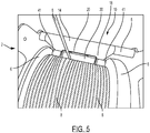
FIG. 5 is a top view of an illustrative embodiment of a press roller spring frame as part of a press roller system in operational engagement with a drum of spooled wire rope in accordance with the present disclosure. - A detailed description of the hereinafter described embodiments of the disclosed apparatus and method are presented herein by way of exemplification and not limitation with reference to the Figures listed above. Although certain embodiments are shown and described in detail, it should be understood that various changes and modifications may be made without departing from the scope of the appended claims. The scope of the present disclosure will in no way be limited to the number of constituting components, the materials thereof, the shapes thereof, the relative arrangement thereof, etc., and are disclosed simply as an example of embodiments of the present disclosure.
- As a preface to the detailed description, it should be noted that, as used in this specification and the appended claims, the singular forms "a", "an" and "the" include plural referents, unless the context clearly dictates otherwise.
- The drawings depict illustrative embodiments of a press
roller spring frame 10 andpress roller system 2. These embodiments may each comprise various structural and functional components that complement one another to provide the unique functionality and performance of the pressroller spring frame 10 andpress roller system 2, the particular structure and function of which will be described in greater detail herein. - Referring to the drawings,
FIG. 1 depicts an illustrative embodiment of a pressroller spring frame 10. Embodiments of the pressroller spring frame 10 may comprise aframe member 12. Theframe member 12 may comprise afirst section 14, asecond section 16, and athird section 18. Thefirst section 14 may be a section of theframe member 12 that is positioned between thesecond section 16 and thethird section 18. Thefirst section 14 may be a bowed, curved, or arcuate-shaped section. The second andthird sections second section 16 may extend a length from one end of thefirst section 14 and thethird section 18 may extend a length from the other end of thefirst section 14, such that thesecond section 16 and thethird section 18 oppose one another with thefirst section 14 operationally positioned therebetween, as depicted inFIG. 1 . - Embodiments of the press
roller spring frame 10 may comprise theframe member 12, or frame, being configured and manufactured using one or more techniques and comprised of one or more complimentary components. For example, theframe member 12 may be organized by having thefirst section 14 and thesecond section 16 be functionally coupled together at their respective ends by means of fastening, such as welding, adhesive, bolts, pins, screws, nails, and other known fastening members. Likewise, thefirst section 14 and thethird sections 18 may be functionally coupled together at their respective ends by means of fastening, such as welding, adhesive, bolts, pins, screws, nails, and other known fastening members. As such, thefirst section 14 may be formed into its arcuate shape and have thereafter the second andthird sections FIG. 1 . Thefirst section 14 may be formed of a type of material having properties that are the same or are different than the properties of the material used to form the second andthird sections first section 14 may be formed of a flexible metal or alloy that may allow thefirst section 14 to flex or elastically deform under force or pressure. On the other hand, in some embodiments, the second andthird sections third sections first section 14 to elastically deform, as will be described in greater detail herein. - Alternatively, the
frame member 12 may be formed of a solid unitary piece of flexible, elastic, pliant, or otherwise bendable material, such as metals and alloys. For example, theframe member 12 may be a metal or alloy member cast in a mold with thefirst section 14 operationally positioned between the second andthird sections FIG. 1 . Theframe member 12 manufactured in this way may be formed of metals, alloys, plastics, organic materials, or other rigid materials that can withstand the application of force applied thereon. Thus, as force is applied to the second orthird sections first section 14 to elastically deform, as will be described in greater detail herein. - Further in example, the
frame member 12 may be comprised of a single unitary piece of metal or alloy and thereafter formed to the desired shape. For example, a piece of sheet metal may be cut to predetermined dimensions and thereafter formed into theframe member 12 by bending, plastically deforming, or otherwise shaping thefirst section 14 into the arcuate-shaped section with the substantially planarsecond section 16 andthird section 18 extending therefrom on opposing sides of the arc of thefirst section 14, as depicted inFIG. 1 . In this configuration, as force is applied to the second orthird sections first section 14 to elastically deform, as will be described in greater detail herein. In some embodiments, the sheet metal of theframe member 12 may besheet 14 gage or 2mm - 17-7ph stainless steel solution annealed. The arcuate shape of thefirst section 14 may be formed by bending the sheet metal in a brake press at or near the midpoint along the length of the sheet, such that the second andthird sections first section 14 after thefirst section 14 is bent. The radius of the arcuate shape of thefirst section 14 may be determined and established, as needed, according to the compressive forces desired based on the specific application in which theframe member 12 will be utilized. Moreover, once formed into theframe member 12, the sheet metal may be heat treated, such as by precipitation hardening, to bring forth the physical and operational properties of theframe member 12, which will be discussed in greater detail herein. - Embodiments of the
frame member 12 may further comprise one ormore holes 15 being positioned in one or both of the second andthird sections holes 15 may be configured to receive afastener 19 or a means of fastening, such as a nut and bolt or other known fasteners. Thefastener 19 may be inserted through thehole 15 in thesecond section 16 and operate to functionally and/or structurally couple thesecond section 16 and thus theplate member 12 to other components of thepress roller system 2, such as a support 4, to be described in greater detail. Thefastener 19 may be inserted through thehole 15 in thethird section 18 and operate to functionally and/or structurally couple thethird section 18 of theplate member 12 to other components of the pressroller spring frame 10, such as abracket 20. - Embodiments of the press
roller spring frame 10 may comprise thebracket 20. Thebracket 20 may comprise amain body 22 having first and second ends 24 and 26 that are configured to protrude or extend perpendicularly from themain body 22. The first and second ends 24 and 26 may have configured therein anaperture 28. Theaperture 28 may be configured to receive therein and retain anaxle 34 of aroller 30, to be described in greater detail. Thebracket 20 may comprise one ormore holes 15 positioned in themain body 22. Theholes 15 may be configured to receive afastener 19 or a means of fastening, such as a nut and bolt or other known fasteners. Thefastener 19 may be inserted through thehole 15 and operate to functionally and/or structurally couple themain body 22 to theplate member 12. In particular,fastener 19 may be inserted through thehole 15 to functionally and/or physically couple themain body 22 of thebracket 20 to at least a portion of thethird section 18, such that thebracket 20 is releasably secured to theplate member 12. - Embodiments of the press
roller spring frame 10 may further comprise thebracket 20 comprising first and second ends 24a and 26a (not depicted) that are each independently and separately coupled to at least a portion of thethird section 18, without the need of themain body 22. Each of the first and second ends 24a and 26a may compriseholes 15 through which thefastener 19 may be utilized to couple the ends 24a and 26a to thethird section 18. Alternatively, each of the first and second ends 24a and 26a may be coupled to thethird section 18 by fastening means such as welding, adhesive, friction fit, crimping, and other known fastening method and techniques. Each of these first and second ends 24a and 26a may further comprise arespective aperture 28 that is configured to receive therein and retain anaxle 34 of theroller 30, such that theroller 30 is configured between the first and second ends 24a and 26a. - Embodiments of the press
roller spring frame 10 may further comprise thebracket 20 being part and portion of thethird section 18. For example, portions of thethird section 18 may be cut, folded or otherwise manipulated to create perpendicular portions (not depicted) that protrude or extend perpendicularly from thethird section 18. These perpendicular portions of thethird section 18 may therefore function in a manner similar to the function of the first and second ends 24 and 26 described above. These perpendicular portions of thethird section 18 may also comprise theapertures 28 described above that are configured to receive therein and retain anaxle 34 of aroller 30, such that theroller 30 is configured between the perpendicular portions of thethird section 18. - Embodiments of the press
roller spring frame 10 may further comprise theroller 30. Theroller 30 may be comprised of one or more roller parts, including for example acentral roller 36 and anouter roller 38 on either end of thecentral roller 36, as illustratively depicted inFIGS. 1 and3 . Each of thecentral roller 36 and theouter rollers 38 may be configured to be inserted onto anaxle 34, about which thecentral roller 36 andouter rollers 38 may independently spin, turn, or otherwise rotate. Each of theouter rollers 38 may have anannular recess 37 on an end thereof. As stated previously, theaxle 34, and thus theroller 30, may be supported in its operation by theapertures 28. To form theroller 30, thecentral roller 36 may be inserted between the first and second ends 24 and 26 of thebracket 20 and theaxle 34 may thereafter be inserted through one of the first and second ends 24 and 26, through thecentral roller 36 and through the remaining one of the first and second ends 24 and 26. Theouter rollers 38 may thereafter be inserted over the ends of theaxle 34 that protrude out from each of the first and second ends 24 and 26, such that theannular recess 37 of each of theouter rollers 38 is visible and theaxle 34 is visible within theannular recess 37. In this way, one ormore fastening members annular recess 37 to physically and functionally engage the distal end of theaxle 34 to secure theouter roller 38 on theaxle 34 and prevent theouter roller 38 from falling off theaxle 34. Thefastening members fastening member 39a is a nut and 39b is a washer, then the distal end of theaxle 34 may be a threaded bolt configured to receive and engage the nut. With thefastening members annular recess 37, thedistal end 41 of eachouter roller 38 extends beyond the fastening member 39, as depicted inFIG. 3 . Moreover, by positioning the first and second ends 24 and 26 of thebracket 20 between thecentral roller 36 and theouter rollers 38, the first and second ends 24 and 26 are kept from extending beyond thedistal end 41 of eachouter roller 38. As such, the opposing distal ends 41 are the furthermost end points of theroller 30, as depicted inFIG. 3 . - Referring again to the drawings,
FIG. 2 depicts an illustrative embodiment of the pressroller spring frame 10. Embodiments of the pressroller spring frame 10 may comprise an angle Z defined between the second andthird sections roller spring frame 10 comes to life as the angle Z is reduced by application of force F on theroller 30. Specifically, under applied force F exerted against theroller 30, the force F attempts to reduce the measure of the angle Z by forcing thethird section 18 toward thesecond section 16 to further bend the arcuate shape of thefirst section 14. However, the spring force stored in the arcuate shape of thefirst section 14 resists the force F and serves to prevent thethird section 18 from advancing toward thesecond section 16, to the extent that it can. In this way, the spring force exerted by thefirst section 14 in opposition to the applied force F operates to press theroller 30 firmly against whatever object is pressing on theroller 30 to exert the applied force F. - Referring again to the drawings,
FIG. 4 depicts an illustrative embodiment of thepress roller system 2, of which the pressroller spring frame 10 may comprise a part. Thepress roller system 2 may further comprise a support 4, a drum orspool 6, a material8, such as a wire, and the pressroller spring frame 10. The support 4, depicted in the Figures with dashed lines, may be a frame member, frame assembly, or other support structure, including for example a winch assembly. The support 4 may be configured to house the drum orspool 6. The drum orspool 6 may further comprise anaxis 7 about which thespool 6 may rotate. Theaxis 7 may be physically coupled or engaged by the support 4. With theaxis 7 supported by the support 4, thespool 6 may rotate freely about theaxis 7 with respect to the support 4. Thespool 6 may be configured to receive thereon thematerial 8, hereinafter referred to as thewire 8. As thespool 6 rotates about theaxis 7, the rotation thereof may pull a length of thewire 8 onto thespool 6. As such, the length of thewire 8 may be wrapped about the diameter of thespool 6 in sequential loops, layer upon layer, until the desired length of thewire 8 is placed on thespool 6. Thewire 8 may be, for example, any material capable of being wrapped about a spool, such as cable, wire rope, rope, wire, cord, or other linear-shaped material that is capable of being wrapped about a cylindrical shape. Further, as thewire 8 is wrapped about thespool 6, tension may be placed on thewire 8 to keep thewire 8 taught with respect to thespool 6. - Embodiments of the
press roller system 2 may further comprise the pressroller spring frame 10. The pressroller spring frame 10 may be configured within the support 4 so as to be physically supported by the support 4 while also in functional engagement with thespool 6 andwire 8. Specifically, thesecond section 16 may be releasably coupled to the support 4 by way of one ormore fasteners 19 being inserted through theholes 15 in thesecond section 16 and corresponding holes in the support 4 to releasably fasten together in structural and functional engagement thesecond section 16 and the support 4, as depicted inFIG. 4 . With theframe member 12 structurally supported by the support 4, theroller 30 may be physically configured in the support 4 to functionally and physically engage thespool 6 and thewire 8 on thespool 6. Embodiments of thepress roller system 2 may further comprise thespool 6 being added within the support 4 after the pressroller spring frame 10 has been positioned within the support 4. In this manner, thespool 6 andwire 8 on thespool 6 may be brought into physical contact and functional engagement with theroller 30. Embodiments of thepress roller system 2 may further comprise thespool 6 being added within the support 4 prior to the pressroller spring frame 10 being positioned within the support 4. In this manner, theroller 30 may be brought into physical contact and functional engagement with thespool 6 and thewire 8 on thespool 6. - Embodiments of the
press roller system 2, including the pressroller spring frame 10, may operate to prevent thewire 8 from becoming tangled, snarled, jumbled, or otherwise disorganized on thespool 6. In operation, thespool 6 presses against theroller 30, or theroller 30 presses against thespool 6, to provide the applied force F discussed above. In response, the spring force stored in thefirst section 14 resists the force F and presses theroller 30 back against thespool 6, or thespool 6 against theroller 30. Moreover, as thespool 6 rotates, theroller 30 likewise rotates, thereby allowing thespool 6 and theroller 30 to remain in physical contact and functional engagement even while thespool 6 and/or theroller 30 rotates. - Embodiments of the
press roller system 2, including the pressroller spring frame 10 may comprise theroller 30 being positioned against thespool 6 at or near the point where thewire 8 begins to wrap around thespool 6. In this configuration, theroller 30 may guide the application of thewire 8 onto thespool 6 at the desired location on the spool 6 (i.e., next to the previous loop of wire 8) and thereafter prevent the wrapped loops ofwire 8 on thespool 6 from unwrapping, dislodging, or otherwise moving in an undesired manner. - Embodiments of the
press roller system 2, including the pressroller spring frame 10 may comprise the pressroller spring frame 10 adapting to the number of layers ofwire 8 on thespool 6. For example, asmore wire 8 is wrapped about thespool 6, multiple layers of thewire 8 are created, which layers increase the diameter of thespool 6. As the diameter of thespool 6 increases, thespool 6 applies the force F against thethird section 18 to push thethird section 18 closer to thesecond section 16 of thespring frame 12, causing thespring frame 12 to elastically deform at thefirst section 14. Yet, the pressroller spring frame 10 is configured to accommodate the applied force F resulting from the increased number of layers of thewire 8 about thespool 6. As described above, thefirst section 14 of theframe member 12 is configured to elastically deform under the applied force F, but not plastically deform. As a result, even as the number of layers of thewire 8 increase, thus causing increased compressive force on thefirst section 14, the spring force of thefirst section 14 nevertheless continues to elastically resist the increased compressive force and provide the opposing force that maintains theroller 30 in physical and functional engagement with the layers ofwire 8 on thespool 6. Moreover, as the compression force increases, due to the increased diameter of thespool 6, or more accurately the multiple layers ofwire 8 on thespool 6, the spring force likewise increases, due in large part to the increased compression on thefirst section 14. In other words, the more thefirst section 14 is compressed, the greater the resulting spring force. - Referring again to the drawings,
FIG. 5 depicts an illustrative embodiment of thepress roller system 2, of which the pressroller spring frame 10 comprises a part. As thespool 6 rotates within the support 4, thewire 8 can be threaded onto the spool in a loop-by-loop, side-by-side, sequential manner, as depicted. As thewire 8 contacts thespool 6, thewire 8 may pass between theroller 30 and the spool 6 (or previous layer of wire 8), such that theroller 30 may guide the placement of thewire 8 in the correct position on the spool 6 (or previous layer of wire 8). Thewire 8 on thespool 6 may press against theroller 30 to cause thethird section 18 to move closer to thesecond section 16, thus compressing thefirst section 14. Yet the spring force of thefirst section 14 resists the compressive force F applied by thewire 8 on thespool 6 and presses theroller 30 back against thewire 8 on thespool 6, or stated another way, maintains theroller 30 in physical and functional engagement with thewire 8 on thespool 6 to prevent thewire 8 from "birdnesting." - Embodiments of the
press roller system 2, including the pressroller spring frame 10 may comprise theroller 30 being configured to press against thespool 6 or thewire 8 on thespool 6 across the entire width of thespool 6, the width being defined between outer exterior walls of thespool 6. As described herein, theroller 30 may comprise acentral roller 36 and twoouter rollers 38 that all together comprise theroller 30 and perform its collective function. Further, with the first and second ends 24 and 26 of thebracket 20 being operatively coupled to theaxle 34 of theroller 30 between thecentral roller 36 and theouter rollers 38, the distal ends 41 of each of theouter rollers 38 are the furthermost points of theroller 30. As such, theroller 30, fromdistal end 41 to opposingdistal end 41, may contact thespool 6 and thewire 8 on thespool 6 across the entire width of thespool 6, as illustratively depicted inFIG. 5 . In this manner, none of the loops of thewire 8 on thespool 6 can escape the physical contact of theroller 30. - Embodiments of the
press roller system 2, including the pressroller spring frame 10 may comprise a stabilizingmember 5 configured to support theframe member 12 at or near thefirst section 14, or even underneath thefirst section 14 between the second andthird sections third section 18 may be coupled to the support 4 and the A-frame shapedframe member 12 may be supported under thefirst section 14 by the stabilizingmember 5. Also, thespool axis 7 may be coupled to the support 4 to support thespool 6 within the support 4. In this way, both the pressroller spring frame 10 and thespool 6 are respectively secured to the support 4, such that thespring frame 10 and thespool 6 cannot retreat from one another under the application of forces to thesystem 2, thespring frame 10 or thespool 6. Understandably, under these forces, thespring frame 10 may be configured to elastically deform as the spool receives more andmore material 8 thereon. The stabilizingmember 5 may be configured to further secure thespring frame 10 to thesupport 2 to allow the first, second, and third sections, 14, 16, and 18, respectively, to elastically deform. - In addition to the components of the
press roller system 2 and the pressroller spring frame 10 described above, methods of wrapping wire about a spool or maintaining wire about a spool may be performed utilizing embodiments of thepress roller system 2 and the pressroller spring frame 10 herein described. The method may comprise providing a spool and a wire to be wrapped about the spool. The method may further comprise providing a press roller spring frame, such as that described herein. The method may comprise inserting the spool and the press roller spring frame within the press roller system, such that they functionally engage one another in a manner consistent with the present disclosure. The method may further comprise threading the wire onto the spool by rotating the spool and maintaining the roller pressed against the spool as the wire is threaded thereon. Pressing the roller against the spool or maintaining the roller against the wire on the spool may be achieved by utilization of the pressroller spring frame 10 described herein in conjunction with thepress roller system 2. - Furthermore, the components defining the above-described press
roller spring frame 10 andspring roller system 2 may be purchased pre-manufactured or manufactured separately and then assembled together. However, any or all of the components may be manufactured simultaneously and integrally joined with one another. Manufacture of these components separately or simultaneously may involve extrusion, pultrusion, vacuum forming, injection molding, blow molding, resin transfer molding, casting, forging, cold rolling, milling, drilling, reaming, turning, grinding, stamping, cutting, bending, welding, soldering, hardening, riveting, punching, plating, 3-D printing, and/or the like. If any of the components are manufactured separately, they may then be coupled with one another in any manner, such as with adhesive, a weld, a fastener (e.g. a bolt, a nut, a screw, a nail, a rivet, a pin, and/or the like), wiring, any combination thereof, and/or the like for example, depending on, among other considerations, the particular material forming the components. Other possible steps might include sand blasting, polishing, powder coating, zinc plating, anodizing, hard anodizing, and/or painting the components for example. - While this disclosure has been described in conjunction with the specific embodiments outlined above, it is evident that many alternatives, modifications and variations will be apparent to those skilled in the art. Accordingly, the preferred embodiments of the present disclosure as set forth above are intended to be illustrative, not limiting. The claims provide the scope of the coverage of the present disclosure and should not be limited to the specific examples provided herein.
Claims (8)
- A spring frame system comprising:an A-frame type frame (10) having an arcuate first section (14) at a connection between a second section (16) and a third section (18);a spool (6) configured to rotate about a spool axis (7) and having a material (8) thereon;a stabilizing member (5) configured to support the frame (10) at or near, or even underneath the arcuate first section (14) between the second and third sections (16, 18); anda member (30) coupled to an exterior face of the third section (18),wherein under a force applied to the member (30) by the material (8) on the spool (6) the first arcuate section (14) elastically deforms and the second and third sections (16, 18) advance toward one another.
- The system of claim 1, wherein the member is a roller (30) configured to rotate about a roller axis.
- The system of claim 2, wherein the spool axis (7) and the roller axis are substantially parallel, and wherein under the force the spool (6) rotates about the spool axis (7) and the roller (30) rotates about the roller axis with the material (8) therebetween.
- The system of claim 3, further comprising a support (4), wherein the spool axis (7) and the second section (16) are coupled to the support.
- The system according to one of claims 2 to 4, wherein the roller axis is substantially orthogonal to a direction of displacement of the second and third sections (16, 18).
- The system according to one of claims 2 to 5, further comprising a bracket (20), wherein the roller (30) is operatively coupled to the bracket (20) and the bracket (20) is coupled to the exterior face of the third section (18).
- The system according to any preceding claim, wherein the member (30) is coupled to the exterior face of the third section (18) near an end of the third section (18) opposite the first arcuate section (14).
- The system according to any preceding claim, wherein the A-frame (10) is a unitary piece of sheet metal.
Applications Claiming Priority (2)
| Application Number | Priority Date | Filing Date | Title |
|---|---|---|---|
| US201562174399P | 2015-06-11 | 2015-06-11 | |
| US15/139,593 US9926159B2 (en) | 2015-06-11 | 2016-04-27 | Press roller spring frame |
Publications (2)
| Publication Number | Publication Date |
|---|---|
| EP3103748A1 EP3103748A1 (en) | 2016-12-14 |
| EP3103748B1 true EP3103748B1 (en) | 2020-01-29 |
Family
ID=56194233
Family Applications (1)
| Application Number | Title | Priority Date | Filing Date |
|---|---|---|---|
| EP16171488.6A Active EP3103748B1 (en) | 2015-06-11 | 2016-05-26 | Press roller spring frame |
Country Status (3)
| Country | Link |
|---|---|
| US (1) | US9926159B2 (en) |
| EP (1) | EP3103748B1 (en) |
| CN (1) | CN106241496B (en) |
Families Citing this family (7)
| Publication number | Priority date | Publication date | Assignee | Title |
|---|---|---|---|---|
| CN107472995A (en) * | 2017-07-10 | 2017-12-15 | 河南宏骏通信工程有限公司 | A kind of communication engineering power supply for construction cable wire winding tube |
| NL2020136B1 (en) * | 2017-12-20 | 2019-06-26 | Hoeflon B V | Winch cable guide, winch comprising said winch cable guide and method for operating the same |
| CN110921423B (en) * | 2019-11-27 | 2022-01-04 | 河南通达电缆股份有限公司 | Wire feeding support frame for wire processing |
| CN111874754B (en) * | 2020-08-10 | 2022-04-19 | 姚广元 | Return cable district section early warning intelligent host computer with gesture detects |
| CN115215148A (en) * | 2022-07-22 | 2022-10-21 | 广东优谷信息科技有限公司 | Network wiring equipment for information engineering and wiring method thereof |
| MX2024003741A (en) * | 2023-04-06 | 2024-11-08 | Illinois Tool Works | The invention relates to a roller for hot stamping. |
| CN116767984B (en) * | 2023-08-17 | 2023-11-07 | 华能太原东山燃机热电有限责任公司 | Cable winding and unwinding device for solar photovoltaic power generation |
Citations (2)
| Publication number | Priority date | Publication date | Assignee | Title |
|---|---|---|---|---|
| US6006044A (en) * | 1996-02-19 | 1999-12-21 | Canon Kabushiki Kaisha | Camera |
| US20020121567A1 (en) * | 2001-03-02 | 2002-09-05 | Fuji Photo Optical Co., Ltd. | Film-winding device for camera |
Family Cites Families (10)
| Publication number | Priority date | Publication date | Assignee | Title |
|---|---|---|---|---|
| US1526087A (en) | 1923-12-12 | 1925-02-10 | Petersen Anker | Tension device |
| US2254255A (en) | 1939-06-05 | 1941-09-02 | Rudolph E Zeruneith | Material unwinding, guiding, and tensioning structure |
| GB670322A (en) * | 1948-05-20 | 1952-04-16 | William Ayrton & Company Ltd | Improvements in or relating to the precision cross-winding of yarns and the like |
| US5803437A (en) * | 1997-03-26 | 1998-09-08 | Paterson; Richard | Chainless drive winch |
| JP3671657B2 (en) * | 1998-02-26 | 2005-07-13 | 日本電気硝子株式会社 | Traverse equipment |
| FI110363B (en) | 1998-09-22 | 2002-12-31 | Metso Paper Inc | Hardware in connection with the web winder |
| DE10250863B4 (en) | 2002-10-31 | 2005-06-02 | Brückner Maschinenbau GmbH | Winding device for web-shaped materials, in particular plastic films |
| DE102004020322A1 (en) | 2004-04-26 | 2005-11-10 | Voith Paper Patent Gmbh | Winding machine for the continuous winding of a material web |
| WO2010058597A1 (en) * | 2008-11-21 | 2010-05-27 | 古河電気工業株式会社 | Wire body take-up device and wire body take-up method |
| CN101780904B (en) * | 2010-02-10 | 2012-07-04 | 上海颐尚电工科技有限公司 | Wire guiding member |
-
2016
- 2016-04-27 US US15/139,593 patent/US9926159B2/en active Active
- 2016-05-26 EP EP16171488.6A patent/EP3103748B1/en active Active
- 2016-06-12 CN CN201610407405.6A patent/CN106241496B/en active Active
Patent Citations (2)
| Publication number | Priority date | Publication date | Assignee | Title |
|---|---|---|---|---|
| US6006044A (en) * | 1996-02-19 | 1999-12-21 | Canon Kabushiki Kaisha | Camera |
| US20020121567A1 (en) * | 2001-03-02 | 2002-09-05 | Fuji Photo Optical Co., Ltd. | Film-winding device for camera |
Also Published As
| Publication number | Publication date |
|---|---|
| US20160362268A1 (en) | 2016-12-15 |
| CN106241496A (en) | 2016-12-21 |
| EP3103748A1 (en) | 2016-12-14 |
| CN106241496B (en) | 2019-05-10 |
| US9926159B2 (en) | 2018-03-27 |
Similar Documents
| Publication | Publication Date | Title |
|---|---|---|
| US9926159B2 (en) | Press roller spring frame | |
| JP3605156B2 (en) | Storage reel for cords, etc. | |
| US10287129B2 (en) | Spool holder and method of supporting spool of wire with spool holder | |
| US20070257148A1 (en) | Quick release coil making machine | |
| JPH1068282A (en) | Rewinding/stretching roller for flexible member | |
| EP2646192B1 (en) | Wire feeding device of a welding machine and method for moving a welding wire | |
| CN105165749A (en) | Clutch return mechanism for a dual-bearing reel | |
| US20210108693A1 (en) | Torque adjustment mechanism | |
| EP1045809A1 (en) | Self-compensating filament tension control device | |
| EP3664999B1 (en) | Manually operated press | |
| US4192473A (en) | Wire reel | |
| US6640484B1 (en) | Fishing line loading device | |
| US20190002231A1 (en) | Wire spool guide | |
| US2993689A (en) | Power spring | |
| JP7116082B2 (en) | Devices for guiding wires in wire binding machines and wire binding machines including such devices | |
| EP1572388B1 (en) | A reel with a support surface arranged on a flexible element and a method of regulating the diameter | |
| CN110004678B (en) | Wire pressing mechanism of wire twisting disc, power machine core and clothes airing machine | |
| US10894693B2 (en) | Counter assembly | |
| CN217616922U (en) | Unwinding roller with adjustable size | |
| KR102083623B1 (en) | Uncoiling system for outer edge ring | |
| WO1991015339A1 (en) | Spring spreading tool | |
| EP1642856B1 (en) | Device and method for rope tension adjustment | |
| BE1002148A5 (en) | Tensioner. | |
| CN220392813U (en) | Fabric winding anti-deviation yarn cylinder | |
| DE102018124597B3 (en) | Manually operated press |
Legal Events
| Date | Code | Title | Description |
|---|---|---|---|
| PUAI | Public reference made under article 153(3) epc to a published international application that has entered the european phase |
Free format text: ORIGINAL CODE: 0009012 |
|
| STAA | Information on the status of an ep patent application or granted ep patent |
Free format text: STATUS: THE APPLICATION HAS BEEN PUBLISHED |
|
| AK | Designated contracting states |
Kind code of ref document: A1 Designated state(s): AL AT BE BG CH CY CZ DE DK EE ES FI FR GB GR HR HU IE IS IT LI LT LU LV MC MK MT NL NO PL PT RO RS SE SI SK SM TR |
|
| AX | Request for extension of the european patent |
Extension state: BA ME |
|
| STAA | Information on the status of an ep patent application or granted ep patent |
Free format text: STATUS: REQUEST FOR EXAMINATION WAS MADE |
|
| 17P | Request for examination filed |
Effective date: 20170614 |
|
| RBV | Designated contracting states (corrected) |
Designated state(s): AL AT BE BG CH CY CZ DE DK EE ES FI FR GB GR HR HU IE IS IT LI LT LU LV MC MK MT NL NO PL PT RO RS SE SI SK SM TR |
|
| STAA | Information on the status of an ep patent application or granted ep patent |
Free format text: STATUS: EXAMINATION IS IN PROGRESS |
|
| 17Q | First examination report despatched |
Effective date: 20180201 |
|
| GRAP | Despatch of communication of intention to grant a patent |
Free format text: ORIGINAL CODE: EPIDOSNIGR1 |
|
| STAA | Information on the status of an ep patent application or granted ep patent |
Free format text: STATUS: GRANT OF PATENT IS INTENDED |
|
| INTG | Intention to grant announced |
Effective date: 20190801 |
|
| GRAS | Grant fee paid |
Free format text: ORIGINAL CODE: EPIDOSNIGR3 |
|
| GRAA | (expected) grant |
Free format text: ORIGINAL CODE: 0009210 |
|
| STAA | Information on the status of an ep patent application or granted ep patent |
Free format text: STATUS: THE PATENT HAS BEEN GRANTED |
|
| AK | Designated contracting states |
Kind code of ref document: B1 Designated state(s): AL AT BE BG CH CY CZ DE DK EE ES FI FR GB GR HR HU IE IS IT LI LT LU LV MC MK MT NL NO PL PT RO RS SE SI SK SM TR |
|
| REG | Reference to a national code |
Ref country code: GB Ref legal event code: FG4D |
|
| REG | Reference to a national code |
Ref country code: CH Ref legal event code: EP |
|
| REG | Reference to a national code |
Ref country code: AT Ref legal event code: REF Ref document number: 1228384 Country of ref document: AT Kind code of ref document: T Effective date: 20200215 |
|
| REG | Reference to a national code |
Ref country code: IE Ref legal event code: FG4D |
|
| REG | Reference to a national code |
Ref country code: DE Ref legal event code: R096 Ref document number: 602016028559 Country of ref document: DE |
|
| RAP2 | Party data changed (patent owner data changed or rights of a patent transferred) |
Owner name: INGERSOLL-RAND INDUSTRIAL U.S., INC. |
|
| REG | Reference to a national code |
Ref country code: NL Ref legal event code: MP Effective date: 20200129 |
|
| PG25 | Lapsed in a contracting state [announced via postgrant information from national office to epo] |
Ref country code: RS Free format text: LAPSE BECAUSE OF FAILURE TO SUBMIT A TRANSLATION OF THE DESCRIPTION OR TO PAY THE FEE WITHIN THE PRESCRIBED TIME-LIMIT Effective date: 20200129 Ref country code: FI Free format text: LAPSE BECAUSE OF FAILURE TO SUBMIT A TRANSLATION OF THE DESCRIPTION OR TO PAY THE FEE WITHIN THE PRESCRIBED TIME-LIMIT Effective date: 20200129 Ref country code: NO Free format text: LAPSE BECAUSE OF FAILURE TO SUBMIT A TRANSLATION OF THE DESCRIPTION OR TO PAY THE FEE WITHIN THE PRESCRIBED TIME-LIMIT Effective date: 20200429 Ref country code: PT Free format text: LAPSE BECAUSE OF FAILURE TO SUBMIT A TRANSLATION OF THE DESCRIPTION OR TO PAY THE FEE WITHIN THE PRESCRIBED TIME-LIMIT Effective date: 20200621 |
|
| REG | Reference to a national code |
Ref country code: LT Ref legal event code: MG4D |
|
| PG25 | Lapsed in a contracting state [announced via postgrant information from national office to epo] |
Ref country code: LV Free format text: LAPSE BECAUSE OF FAILURE TO SUBMIT A TRANSLATION OF THE DESCRIPTION OR TO PAY THE FEE WITHIN THE PRESCRIBED TIME-LIMIT Effective date: 20200129 Ref country code: SE Free format text: LAPSE BECAUSE OF FAILURE TO SUBMIT A TRANSLATION OF THE DESCRIPTION OR TO PAY THE FEE WITHIN THE PRESCRIBED TIME-LIMIT Effective date: 20200129 Ref country code: HR Free format text: LAPSE BECAUSE OF FAILURE TO SUBMIT A TRANSLATION OF THE DESCRIPTION OR TO PAY THE FEE WITHIN THE PRESCRIBED TIME-LIMIT Effective date: 20200129 Ref country code: IS Free format text: LAPSE BECAUSE OF FAILURE TO SUBMIT A TRANSLATION OF THE DESCRIPTION OR TO PAY THE FEE WITHIN THE PRESCRIBED TIME-LIMIT Effective date: 20200529 Ref country code: BG Free format text: LAPSE BECAUSE OF FAILURE TO SUBMIT A TRANSLATION OF THE DESCRIPTION OR TO PAY THE FEE WITHIN THE PRESCRIBED TIME-LIMIT Effective date: 20200429 Ref country code: GR Free format text: LAPSE BECAUSE OF FAILURE TO SUBMIT A TRANSLATION OF THE DESCRIPTION OR TO PAY THE FEE WITHIN THE PRESCRIBED TIME-LIMIT Effective date: 20200430 |
|
| PG25 | Lapsed in a contracting state [announced via postgrant information from national office to epo] |
Ref country code: NL Free format text: LAPSE BECAUSE OF FAILURE TO SUBMIT A TRANSLATION OF THE DESCRIPTION OR TO PAY THE FEE WITHIN THE PRESCRIBED TIME-LIMIT Effective date: 20200129 |
|
| REG | Reference to a national code |
Ref country code: GB Ref legal event code: 732E Free format text: REGISTERED BETWEEN 20200903 AND 20200910 |
|
| PG25 | Lapsed in a contracting state [announced via postgrant information from national office to epo] |
Ref country code: CZ Free format text: LAPSE BECAUSE OF FAILURE TO SUBMIT A TRANSLATION OF THE DESCRIPTION OR TO PAY THE FEE WITHIN THE PRESCRIBED TIME-LIMIT Effective date: 20200129 Ref country code: RO Free format text: LAPSE BECAUSE OF FAILURE TO SUBMIT A TRANSLATION OF THE DESCRIPTION OR TO PAY THE FEE WITHIN THE PRESCRIBED TIME-LIMIT Effective date: 20200129 Ref country code: SK Free format text: LAPSE BECAUSE OF FAILURE TO SUBMIT A TRANSLATION OF THE DESCRIPTION OR TO PAY THE FEE WITHIN THE PRESCRIBED TIME-LIMIT Effective date: 20200129 Ref country code: LT Free format text: LAPSE BECAUSE OF FAILURE TO SUBMIT A TRANSLATION OF THE DESCRIPTION OR TO PAY THE FEE WITHIN THE PRESCRIBED TIME-LIMIT Effective date: 20200129 Ref country code: ES Free format text: LAPSE BECAUSE OF FAILURE TO SUBMIT A TRANSLATION OF THE DESCRIPTION OR TO PAY THE FEE WITHIN THE PRESCRIBED TIME-LIMIT Effective date: 20200129 Ref country code: DK Free format text: LAPSE BECAUSE OF FAILURE TO SUBMIT A TRANSLATION OF THE DESCRIPTION OR TO PAY THE FEE WITHIN THE PRESCRIBED TIME-LIMIT Effective date: 20200129 Ref country code: EE Free format text: LAPSE BECAUSE OF FAILURE TO SUBMIT A TRANSLATION OF THE DESCRIPTION OR TO PAY THE FEE WITHIN THE PRESCRIBED TIME-LIMIT Effective date: 20200129 Ref country code: SM Free format text: LAPSE BECAUSE OF FAILURE TO SUBMIT A TRANSLATION OF THE DESCRIPTION OR TO PAY THE FEE WITHIN THE PRESCRIBED TIME-LIMIT Effective date: 20200129 |
|
| REG | Reference to a national code |
Ref country code: DE Ref legal event code: R097 Ref document number: 602016028559 Country of ref document: DE |
|
| REG | Reference to a national code |
Ref country code: AT Ref legal event code: MK05 Ref document number: 1228384 Country of ref document: AT Kind code of ref document: T Effective date: 20200129 |
|
| PLBE | No opposition filed within time limit |
Free format text: ORIGINAL CODE: 0009261 |
|
| STAA | Information on the status of an ep patent application or granted ep patent |
Free format text: STATUS: NO OPPOSITION FILED WITHIN TIME LIMIT |
|
| 26N | No opposition filed |
Effective date: 20201030 |
|
| REG | Reference to a national code |
Ref country code: DE Ref legal event code: R082 Ref document number: 602016028559 Country of ref document: DE Representative=s name: MURGITROYD GERMANY PATENTANWALTSGESELLSCHAFT M, DE Ref country code: DE Ref legal event code: R082 Ref document number: 602016028559 Country of ref document: DE Representative=s name: HL KEMPNER PATENTANWALT, RECHTSANWALT, SOLICIT, DE Ref country code: DE Ref legal event code: R082 Ref document number: 602016028559 Country of ref document: DE Representative=s name: MURGITROYD & COMPANY, DE |
|
| PG25 | Lapsed in a contracting state [announced via postgrant information from national office to epo] |
Ref country code: AT Free format text: LAPSE BECAUSE OF FAILURE TO SUBMIT A TRANSLATION OF THE DESCRIPTION OR TO PAY THE FEE WITHIN THE PRESCRIBED TIME-LIMIT Effective date: 20200129 Ref country code: MC Free format text: LAPSE BECAUSE OF FAILURE TO SUBMIT A TRANSLATION OF THE DESCRIPTION OR TO PAY THE FEE WITHIN THE PRESCRIBED TIME-LIMIT Effective date: 20200129 Ref country code: IT Free format text: LAPSE BECAUSE OF FAILURE TO SUBMIT A TRANSLATION OF THE DESCRIPTION OR TO PAY THE FEE WITHIN THE PRESCRIBED TIME-LIMIT Effective date: 20200129 Ref country code: LI Free format text: LAPSE BECAUSE OF NON-PAYMENT OF DUE FEES Effective date: 20200531 Ref country code: CH Free format text: LAPSE BECAUSE OF NON-PAYMENT OF DUE FEES Effective date: 20200531 |
|
| PG25 | Lapsed in a contracting state [announced via postgrant information from national office to epo] |
Ref country code: SI Free format text: LAPSE BECAUSE OF FAILURE TO SUBMIT A TRANSLATION OF THE DESCRIPTION OR TO PAY THE FEE WITHIN THE PRESCRIBED TIME-LIMIT Effective date: 20200129 Ref country code: PL Free format text: LAPSE BECAUSE OF FAILURE TO SUBMIT A TRANSLATION OF THE DESCRIPTION OR TO PAY THE FEE WITHIN THE PRESCRIBED TIME-LIMIT Effective date: 20200129 |
|
| REG | Reference to a national code |
Ref country code: BE Ref legal event code: MM Effective date: 20200531 |
|
| PG25 | Lapsed in a contracting state [announced via postgrant information from national office to epo] |
Ref country code: LU Free format text: LAPSE BECAUSE OF NON-PAYMENT OF DUE FEES Effective date: 20200526 |
|
| PG25 | Lapsed in a contracting state [announced via postgrant information from national office to epo] |
Ref country code: IE Free format text: LAPSE BECAUSE OF NON-PAYMENT OF DUE FEES Effective date: 20200526 |
|
| PG25 | Lapsed in a contracting state [announced via postgrant information from national office to epo] |
Ref country code: BE Free format text: LAPSE BECAUSE OF NON-PAYMENT OF DUE FEES Effective date: 20200531 |
|
| REG | Reference to a national code |
Ref country code: DE Ref legal event code: R082 Ref document number: 602016028559 Country of ref document: DE Representative=s name: MURGITROYD GERMANY PATENTANWALTSGESELLSCHAFT M, DE Ref country code: DE Ref legal event code: R082 Ref document number: 602016028559 Country of ref document: DE Representative=s name: MURGITROYD & COMPANY, DE Ref country code: DE Ref legal event code: R081 Ref document number: 602016028559 Country of ref document: DE Owner name: INGERSOLL-RAND INDUSTRIAL U.S., INC. (N.D.GES., US Free format text: FORMER OWNER: INGERSOLL-RAND COMPANY, DAVIDSON, N.C., US |
|
| PG25 | Lapsed in a contracting state [announced via postgrant information from national office to epo] |
Ref country code: TR Free format text: LAPSE BECAUSE OF FAILURE TO SUBMIT A TRANSLATION OF THE DESCRIPTION OR TO PAY THE FEE WITHIN THE PRESCRIBED TIME-LIMIT Effective date: 20200129 Ref country code: MT Free format text: LAPSE BECAUSE OF FAILURE TO SUBMIT A TRANSLATION OF THE DESCRIPTION OR TO PAY THE FEE WITHIN THE PRESCRIBED TIME-LIMIT Effective date: 20200129 Ref country code: CY Free format text: LAPSE BECAUSE OF FAILURE TO SUBMIT A TRANSLATION OF THE DESCRIPTION OR TO PAY THE FEE WITHIN THE PRESCRIBED TIME-LIMIT Effective date: 20200129 |
|
| PG25 | Lapsed in a contracting state [announced via postgrant information from national office to epo] |
Ref country code: MK Free format text: LAPSE BECAUSE OF FAILURE TO SUBMIT A TRANSLATION OF THE DESCRIPTION OR TO PAY THE FEE WITHIN THE PRESCRIBED TIME-LIMIT Effective date: 20200129 Ref country code: AL Free format text: LAPSE BECAUSE OF FAILURE TO SUBMIT A TRANSLATION OF THE DESCRIPTION OR TO PAY THE FEE WITHIN THE PRESCRIBED TIME-LIMIT Effective date: 20200129 |
|
| P01 | Opt-out of the competence of the unified patent court (upc) registered |
Free format text: CASE NUMBER: UPC_APP_327112/2023 Effective date: 20230523 |
|
| PGFP | Annual fee paid to national office [announced via postgrant information from national office to epo] |
Ref country code: DE Payment date: 20250529 Year of fee payment: 10 |
|
| PGFP | Annual fee paid to national office [announced via postgrant information from national office to epo] |
Ref country code: GB Payment date: 20250523 Year of fee payment: 10 |
|
| PGFP | Annual fee paid to national office [announced via postgrant information from national office to epo] |
Ref country code: FR Payment date: 20250526 Year of fee payment: 10 |