EP3103527A1 - Information processing device and assignment method for input device - Google Patents
Information processing device and assignment method for input device Download PDFInfo
- Publication number
- EP3103527A1 EP3103527A1 EP15746704.4A EP15746704A EP3103527A1 EP 3103527 A1 EP3103527 A1 EP 3103527A1 EP 15746704 A EP15746704 A EP 15746704A EP 3103527 A1 EP3103527 A1 EP 3103527A1
- Authority
- EP
- European Patent Office
- Prior art keywords
- user
- login
- information processing
- assignment
- inputting device
- Prior art date
- Legal status (The legal status is an assumption and is not a legal conclusion. Google has not performed a legal analysis and makes no representation as to the accuracy of the status listed.)
- Granted
Links
Images





Classifications
-
- A—HUMAN NECESSITIES
- A63—SPORTS; GAMES; AMUSEMENTS
- A63F—CARD, BOARD, OR ROULETTE GAMES; INDOOR GAMES USING SMALL MOVING PLAYING BODIES; VIDEO GAMES; GAMES NOT OTHERWISE PROVIDED FOR
- A63F13/00—Video games, i.e. games using an electronically generated display having two or more dimensions
- A63F13/70—Game security or game management aspects
- A63F13/79—Game security or game management aspects involving player-related data, e.g. identities, accounts, preferences or play histories
-
- A—HUMAN NECESSITIES
- A63—SPORTS; GAMES; AMUSEMENTS
- A63F—CARD, BOARD, OR ROULETTE GAMES; INDOOR GAMES USING SMALL MOVING PLAYING BODIES; VIDEO GAMES; GAMES NOT OTHERWISE PROVIDED FOR
- A63F13/00—Video games, i.e. games using an electronically generated display having two or more dimensions
- A63F13/20—Input arrangements for video game devices
- A63F13/21—Input arrangements for video game devices characterised by their sensors, purposes or types
- A63F13/213—Input arrangements for video game devices characterised by their sensors, purposes or types comprising photodetecting means, e.g. cameras, photodiodes or infrared cells
-
- A—HUMAN NECESSITIES
- A63—SPORTS; GAMES; AMUSEMENTS
- A63F—CARD, BOARD, OR ROULETTE GAMES; INDOOR GAMES USING SMALL MOVING PLAYING BODIES; VIDEO GAMES; GAMES NOT OTHERWISE PROVIDED FOR
- A63F13/00—Video games, i.e. games using an electronically generated display having two or more dimensions
- A63F13/20—Input arrangements for video game devices
- A63F13/22—Setup operations, e.g. calibration, key configuration or button assignment
-
- A—HUMAN NECESSITIES
- A63—SPORTS; GAMES; AMUSEMENTS
- A63F—CARD, BOARD, OR ROULETTE GAMES; INDOOR GAMES USING SMALL MOVING PLAYING BODIES; VIDEO GAMES; GAMES NOT OTHERWISE PROVIDED FOR
- A63F13/00—Video games, i.e. games using an electronically generated display having two or more dimensions
- A63F13/20—Input arrangements for video game devices
- A63F13/23—Input arrangements for video game devices for interfacing with the game device, e.g. specific interfaces between game controller and console
- A63F13/235—Input arrangements for video game devices for interfacing with the game device, e.g. specific interfaces between game controller and console using a wireless connection, e.g. infrared or piconet
-
- A—HUMAN NECESSITIES
- A63—SPORTS; GAMES; AMUSEMENTS
- A63F—CARD, BOARD, OR ROULETTE GAMES; INDOOR GAMES USING SMALL MOVING PLAYING BODIES; VIDEO GAMES; GAMES NOT OTHERWISE PROVIDED FOR
- A63F13/00—Video games, i.e. games using an electronically generated display having two or more dimensions
- A63F13/25—Output arrangements for video game devices
-
- A—HUMAN NECESSITIES
- A63—SPORTS; GAMES; AMUSEMENTS
- A63F—CARD, BOARD, OR ROULETTE GAMES; INDOOR GAMES USING SMALL MOVING PLAYING BODIES; VIDEO GAMES; GAMES NOT OTHERWISE PROVIDED FOR
- A63F13/00—Video games, i.e. games using an electronically generated display having two or more dimensions
- A63F13/30—Interconnection arrangements between game servers and game devices; Interconnection arrangements between game devices; Interconnection arrangements between game servers
- A63F13/35—Details of game servers
-
- A—HUMAN NECESSITIES
- A63—SPORTS; GAMES; AMUSEMENTS
- A63F—CARD, BOARD, OR ROULETTE GAMES; INDOOR GAMES USING SMALL MOVING PLAYING BODIES; VIDEO GAMES; GAMES NOT OTHERWISE PROVIDED FOR
- A63F13/00—Video games, i.e. games using an electronically generated display having two or more dimensions
- A63F13/90—Constructional details or arrangements of video game devices not provided for in groups A63F13/20 or A63F13/25, e.g. housing, wiring, connections or cabinets
- A63F13/95—Storage media specially adapted for storing game information, e.g. video game cartridges
-
- G—PHYSICS
- G06—COMPUTING OR CALCULATING; COUNTING
- G06F—ELECTRIC DIGITAL DATA PROCESSING
- G06F21/00—Security arrangements for protecting computers, components thereof, programs or data against unauthorised activity
- G06F21/30—Authentication, i.e. establishing the identity or authorisation of security principals
-
- G—PHYSICS
- G06—COMPUTING OR CALCULATING; COUNTING
- G06F—ELECTRIC DIGITAL DATA PROCESSING
- G06F21/00—Security arrangements for protecting computers, components thereof, programs or data against unauthorised activity
- G06F21/70—Protecting specific internal or peripheral components, in which the protection of a component leads to protection of the entire computer
- G06F21/82—Protecting input, output or interconnection devices
- G06F21/83—Protecting input, output or interconnection devices input devices, e.g. keyboards, mice or controllers thereof
-
- G—PHYSICS
- G06—COMPUTING OR CALCULATING; COUNTING
- G06F—ELECTRIC DIGITAL DATA PROCESSING
- G06F3/00—Input arrangements for transferring data to be processed into a form capable of being handled by the computer; Output arrangements for transferring data from processing unit to output unit, e.g. interface arrangements
- G06F3/01—Input arrangements or combined input and output arrangements for interaction between user and computer
- G06F3/048—Interaction techniques based on graphical user interfaces [GUI]
- G06F3/0487—Interaction techniques based on graphical user interfaces [GUI] using specific features provided by the input device, e.g. functions controlled by the rotation of a mouse with dual sensing arrangements, or of the nature of the input device, e.g. tap gestures based on pressure sensed by a digitiser
- G06F3/0489—Interaction techniques based on graphical user interfaces [GUI] using specific features provided by the input device, e.g. functions controlled by the rotation of a mouse with dual sensing arrangements, or of the nature of the input device, e.g. tap gestures based on pressure sensed by a digitiser using dedicated keyboard keys or combinations thereof
-
- G—PHYSICS
- G06—COMPUTING OR CALCULATING; COUNTING
- G06F—ELECTRIC DIGITAL DATA PROCESSING
- G06F2221/00—Indexing scheme relating to security arrangements for protecting computers, components thereof, programs or data against unauthorised activity
- G06F2221/21—Indexing scheme relating to G06F21/00 and subgroups addressing additional information or applications relating to security arrangements for protecting computers, components thereof, programs or data against unauthorised activity
- G06F2221/2105—Dual mode as a secondary aspect
-
- G—PHYSICS
- G06—COMPUTING OR CALCULATING; COUNTING
- G06F—ELECTRIC DIGITAL DATA PROCESSING
- G06F2221/00—Indexing scheme relating to security arrangements for protecting computers, components thereof, programs or data against unauthorised activity
- G06F2221/21—Indexing scheme relating to G06F21/00 and subgroups addressing additional information or applications relating to security arrangements for protecting computers, components thereof, programs or data against unauthorised activity
- G06F2221/2109—Game systems
-
- G—PHYSICS
- G06—COMPUTING OR CALCULATING; COUNTING
- G06F—ELECTRIC DIGITAL DATA PROCESSING
- G06F2221/00—Indexing scheme relating to security arrangements for protecting computers, components thereof, programs or data against unauthorised activity
- G06F2221/21—Indexing scheme relating to G06F21/00 and subgroups addressing additional information or applications relating to security arrangements for protecting computers, components thereof, programs or data against unauthorised activity
- G06F2221/2117—User registration
Definitions
- the present invention relates to a technology for assigning an inputting device to a user in an information processing apparatus.
- a game apparatus advances a game on the basis of operation information of a game controller operated by a user.
- various inputting devices including not only a game controller but also a keyboard and so forth are connected to a game apparatus such that the user can provide a variety of operation information of the inputting devices to the game apparatus.
- the game apparatus may inquire a user about who will use the inputting device. In this case, by declaring that the user itself uses the inputting device to the game apparatus, the game apparatus assigns the inputting device to the declaring user and, as a result, the game apparatus can recognize that operation information from the inputting device originates from the declaring user.
- the game apparatus can link the inputting device and the user to each other with certainty, and it can be considered that the technique is an effective technique.
- the user receives an inquiry every time an inputting device is connected to the game apparatus, and some user may feel the linkage work cumbersome. Therefore, development of a technology for suitably assigning an inputting device connected to a game apparatus to a user is demanded.
- an information processing apparatus includes an assignment processing unit configured to assign an inputting device to a user who is in a login state, and an accepting unit configured to accept an input from the inputting device.
- the assignment processing unit controls an assignment process of the inputting device in response to a number of users who are in the login state.
- a method for assigning an inputting device to a user includes controlling an assignment process of an inputting device in response to the number of users who are in a login state.
- FIG. 1 depicts an information processing system 1 according to an embodiment of the present invention.
- the information processing system 1 includes an information processing apparatus 10 which is a user terminal, and a server 5.
- An access point (hereinafter referred to as "AP") 8 has functions of a wireless access point and a router, and the information processing apparatus 10 connects to the access point 8 by wireless connection or wire connection and connects the server 5 on a network 3 for communication.
- AP access point
- An auxiliary storage apparatus 2 is a mass storage apparatus such as an HDD (hard disk drive) or a flash memory and may be an external storage apparatus which is connected to the information processing apparatus 10 by a USB (universal serial bus) or the like or may be a built-in storage apparatus.
- An outputting apparatus 4 may be a television set having a display unit which outputs an image and a speaker which outputs sound or may be a computer display unit.
- the information processing apparatus 10 is connected to a game controller 6, which is operated by a user, by wireless connection or wire connection, and the game controller 6 outputs an operation signal representative of a result of an operation by the user to the information processing apparatus 10.
- the information processing apparatus 10 accepts an operation signal from the game controller 6, then it reflects the operation on processing of an OS (system software) or an application and outputs a result of processing from the outputting apparatus 4.
- the game controller 6 includes a plurality of inputting units such as a plurality of push-type operation buttons, an analog stick capable of inputting an analog amount and a rotary button.
- the information processing apparatus 10 may be a game apparatus which executes a game program, and the game controller 6 may be an inputting device which provides operation information of a user to the game apparatus.
- the game controller 6 is an example of an inputting device for inputting operation information to the information processing apparatus 10.
- a device similar to the game controller 6 for providing operation information to a game program in order that the user may play a game is available.
- the game controller 6 and a device similar to the game controller 6 are each referred to as "main device" herein, and the user can play a game by using the main device singly.
- an inputting device also a device used auxiliarily when the user plays a game using a main device is available.
- a device such as a keyboard, a mouse or a headset is available and is a device to be used auxiliarily during a game play assuming the presence of a main device.
- a keyboard is used to input a message for some other user having a connection to the network 3 during a game play.
- a headset with a microphone is used for communicating with some other user during a game play.
- Such devices as just described are different from the main device and are not used for operation of a game character but are used auxiliarily to the end. In the present specification, such a device as just described is referred to as "sub device.”
- a game program may accept not only an input from the main device but also an input from the sub device to advance a game. Also in this case, the game program operates supposing that the user operates the main device, and is capable of operating without the sub device. Conversely speaking, the game program does not operate only with operation information from the sub device, and, in this sense, an inputting device which by itself can cause a game to operate may be defined as the main device and an inputting device capable of being used together with the main device may be defined as sub device.
- a definition file in which attribute information which defines whether each of plural kinds of inputting devices capable of being connected to the information processing apparatus 10 is a main device or a sub device in advance is recorded is retained. It is to be noted that the definition file can be updated and, for example, if a game capable of operating only by an input from a headset with a microphone is developed, then the definition file may be updated, for example, by system update such that the headset is managed as the main device.
- the main device and the sub device are inputting devices to be assigned to login users. It is to be noted that inputting devices which cannot be assigned to a login user exist from among inputting devices, and one of such inputting devices is a camera 7 for inputting a picked up image to the information processing apparatus 10.
- the camera 7 which is an image pickup apparatus is provided in the proximity of the outputting apparatus 4 and picks up an image of a space around the outputting apparatus 4. While an example is depicted in FIG. 1 in which the camera 7 is attached to an upper portion of the outputting apparatus 4, the camera 7 may be disposed at a side portion or a lower portion of the outputting apparatus 4, and, in any event, the camera 7 is disposed at a position at which an image of the user positioned in front of the outputting apparatus 4 can be picked up.
- the camera 7 may be a stereo camera.
- the server 5 provides a network service to a user of the information processing system 1.
- the server 5 manages a network account for specifying each user, and each user uses its network account to sign in to a network service provided by the server 5.
- the user can register save data of a game or a trophy which is a virtual award article acquired during game play into the server 5 by signing in to the network service from the information processing apparatus 10. Further, the user can be connected to another user via the network 3 to send or receive chat messages and voice messages.
- a button configuration of the game controller 6 as an example of the inputting device is described below.
- FIG. 2(a) depicts an appearance configuration of the upper face of the game controller.
- the user would grasp a left side grip portion 78b with the left hand thereof and grasp a right side grip portion 78a with the right hand thereof to operate the game controller 6.
- a direction key 71 On an upper face of a housing of the game controller 6, a direction key 71, analog sticks 77a and 77b and four different operation buttons 76 which are inputting units are provided.
- the four different buttons 72 to 75 have different figures in different colors in order to allow distinction among them.
- a touch pad 79 is provided at a flat region between the direction key 71 and operation buttons 76 on the upper face of the housing.
- the touch pad 79 also functions as a press-type button which is depressed down when the user pushes and comes back to the original position when the user releases its hand.
- a function button 80 is provided between the two analog sticks 77a and 77b.
- the function button 80 is used to switch on the power supply to the game controller 6 and simultaneously activate a communication function for connecting the game controller 6 and the information processing apparatus 10 to each other. If the game controller 6 is newly connected, then the information processing apparatus 10 executes a login process of a user. It is to be noted that, when the main power supply to the information processing apparatus 10 is off, if the function button 80 is depressed, then the information processing apparatus 10 accepts a connection request transmitted thereto from the game controller 6 as an instruction for switching on the main power supply. As a result, after the main power supply to the information processing apparatus 10 is switched on, the information processing apparatus 10 executes a login process of a user.
- a SHARE button 81 is provided between the touch pad 79 and the direction key 71.
- the SHARE button 81 is utilized to input an instruction from the user to the OS or system software of the information processing apparatus 10.
- an OPTIONS button 82 is provided between the touch pad 79 and the operation buttons 76.
- the OPTIONS button 82 is utilized to input an instruction from the user to an application (game) executed in the information processing apparatus 10.
- Both of the SHARE button 81 and the OPTIONS button 82 may be formed as push-type buttons.
- FIG. 2(b) depicts an appearance configuration of the back side face of the game controller.
- the touch pad 79 is provided so as to extend from the upper face of the housing, and a transversely elongated light emitting section 85 is provided on the lower side of the back side face of the housing.
- the light emitting section 85 has red (R), green (G) and blue (B) LEDs (light emitting diodes), which are turned on in accordance with emission color information transmitted thereto from the information processing apparatus 10. Where two game controllers 6a and 6b are used as depicted in FIG.
- the information processing apparatus 10 may determine the lighting colors of the light emitting sections 85 of the game controllers 6a and 6b to different colors, to red and green, so that the users A and B can distinguish the respective game controller 6. Consequently, since each user can recognize the game controller 6 used by the user itself from the lighting color of the light emitting section 85, the possibility that the game controller 6 may be mistaken decreases.
- an upper side button 83a and a lower side button 84a are provided at leftwardly and rightwardly symmetrical positions in the longitudinal direction.
- the upper side button 83a and the lower side button 84a are operated by the forefinger and the middle finger of the right hand of the user, respectively, and the upper side button 83b and the lower side button 84b are operated by the forefinger and the middle filter of the left hand of the user, respectively.
- the light emitting section 85 is provided between the arrangement of the upper side button 83a and the lower side button 84a on the right side and the arrangement of the upper side button 83b and the lower side button 84b on the left side as depicted in FIG. 2(b) , it is not hidden by any of the fingers which operate associated buttons, and the camera 7 can suitably pick up an image of the light emitting section 85 which is in an on state.
- the upper side buttons 83 may be configured as push-type buttons
- the lower side buttons 84 may be configured as trigger-type buttons supported for turning motion.
- FIG. 3 depicts a configuration of the game controller 6.
- the game controller 6 includes a wireless communication module 90, a processing section 91, the light emitting section 85, and a vibrator 98.
- the wireless communication module 90 has a function of transmitting and receiving data to and from a wireless communication module of the information processing apparatus 10.
- the processing section 91 executes an intended process of the game controller 6.
- the processing section 91 has a main controlling unit 92, an input acceptance unit 93, a light emission controlling unit 94, a three-axis acceleration sensor 95, a three-axis gyro sensor 96 and a driving controlling unit 97.
- the main controlling unit 92 carries out transmission and reception of necessary data to and from the wireless communication module 90.
- the input acceptance unit 93 accepts input information from such inputting units as the direction key 71, operation buttons 76, analog sticks 77, touch pad 79, function button 80, SHARE button 81, OPTION button 82, upper side buttons 83 and lower side buttons 84 and sends the input information to the main controlling unit 92.
- the main controlling unit 92 converts the received input information into a predetermined control signal as occasion demands and supplies the control signal to the wireless communication module 90.
- the wireless communication module 90 sends the control signal to the information processing apparatus 10 at a predetermined timing.
- the light emission controlling unit 94 controls emission of light from a red LED 87, a green LED 88 and a blue LED 89 which configure the light emitting section 85.
- the information processing apparatus 10 executes a login process of a user.
- the system software of the information processing apparatus 10 determines a lighting color of the light emitting section 85 of the game controller 6 from which the connection request has been received and transmits the lighting color information to the game controller 6.
- the system software preferably analyzes the color information included in the space whose image is picked up by the camera 7 and specifies colors which are not included in environment colors as far as possible to determine a lighting color of the light emitting section 85. This makes it possible to suitably detect the light emitting section 85 which is to be turned on with the designated light color from the picked up image of the camera 7 after the light emitting section 85 is turned on.
- An image picked up by the camera 7 may be provided to the information processing apparatus 10 such that a result of detection of a movement of the game controller 6 or of the user is utilized for game advancement. Accordingly, the camera 7 functions as an inputting device to the information processing apparatus 10.
- the lighting color information received by the wireless communication module 90 is passed to the main controlling unit 92, and the main controlling unit 92 notifies the light emission controlling unit 94 of the lighting color information. Consequently, the light emission controlling unit 94 can control the light emitting section 85 to emit light with the designated lighting color.
- the vibrator 98 is configured including an eccentric motor and so forth and is driven by the driving controlling unit 97.
- the three-axis acceleration sensor 95 detects acceleration components in the three-axis directions of the XYZ directions of the game controller 6, and the three-axis gyro sensor 96 detects angular velocities in an XZ plane, a ZY plane and a YX plane.
- FIG. 4 depicts a functional block diagram of the information processing apparatus 10.
- the information processing apparatus 10 is configured from a main power supply button 20, a power supply ON LED 21, a standby LED 22, a system controller 24, a clock 26, a device controller 30, a media drive 32, a USB module 34, a flash memory 36, a wireless communication module 38, a wire communication module 40, a sub system 50 and a main system 60.
- the main system 60 includes a main CPU (central processing unit), a memory and a memory controller which are main storage apparatuses, a GPU (graphics processing unit) and so forth.
- the GPU is utilized principally for arithmetic operation processing of a game program.
- the functions mentioned are configured as a system-on-chip on a single chip.
- the main CPU starts up the OS and has a function of executing an application installed in the auxiliary storage apparatus 2 under an environment provided by the OS.
- the sub system 50 includes a sub CPU, a memory and a memory controller which are main storage apparatuses, and so forth, but does not include a GPU.
- the number of circuit gates of the sub CPU is smaller than that of the main CPU, and the operation power consumption of the sub CPU is lower than that of the main CPU.
- the sub CPU operates while the main CPU is in a standby state as described hereinabove, and the processing functions of the sub CPU are restricted in order to suppress the power consumption low. It is to be noted that the sub CPU and the memory may be formed on different chips from each other.
- the main power supply button 20 is an inputting unit to which operation inputting is carried out by the user and is provided on a front face of the housing of the information processing apparatus 10.
- the main power supply button 20 is operated to turn on or off the power supply to the main system 60 of the information processing apparatus 10.
- that the main power supply is in an on state signifies that the main system 60 is in an active state
- that the main power supply is in an off state signifies that the main system 60 is in a standby state.
- the power supply ON LED 21 is turned on when the main power supply button 20 is turned on, and the standby LED 22 is turned on when the main power supply button 20 is turned off.
- the system controller 24 detects depression of the main power supply button 20 by the user. If the main power supply button 20 is depressed when the main power supply is in an off state, then the system controller 24 acquires the depression operation as an "on instruction.” However, if the main power supply button 20 is depressed when the main power supply is in an on state, then the system controller 24 acquires the depression operation as an "off instruction.” After the system controller 24 acquires the on instruction, the main system 60 executes a login process of a user.
- the main CPU has a function of executing a game program installed in the auxiliary storage apparatus 2 or a ROM (read-only memory) medium 44 while the sub CPU does not have such a function as just described.
- the sub CPU has a function of accessing the auxiliary storage apparatus 2 and a function of transmitting and receiving data to and from the server 5.
- the sub CPU is configured so as to have only such restricted processing functions and therefore can operate with low power consumption in comparison with the main CPU.
- the functions of the sub CPU are executed while the main CPU is in a standby state. Since the sub system 50 is operative when the main system 60 is in a standby state, the information processing apparatus 10 normally maintains a sign-in state in the network service provided by the server 5.
- the clock 26 is a real time clock and generates and supplies date and time information at present to the system controller 24, sub system 50 and main system 60.
- the device controller 30 is configured as an LSI (large-scale integrated circuit) which executes transfer of information between devices like a south bridge. As depicted in FIG. 4 , to the device controller 30, such devices as system controller 24, media drive 32, USB module 34, flash memory 36, wireless communication module 38, wire communication module 40, sub system 50 and main system 60 are connected. The device controller 30 absorbs differences in electric characteristics of and differences in data transfer speed between the devices to control timings of data transfer.
- LSI large-scale integrated circuit
- the media drive 32 is a drive apparatus which drives, when a ROM medium 44 in which application software of a game and so forth and license information are recorded is loaded in the media drive 32, the ROM medium 44 and reads out a program, data and so forth from the ROM medium 44.
- the ROM medium 44 is a read-only recording medium such as an optical disk, a magneto-optical disk or a Blu-ray disk.
- the USB module 34 is a module for connecting to an external apparatus by a USB cable.
- the USB module 34 connects to the auxiliary storage apparatus 2 and the camera 7 through a USB cable.
- the USB module 34 may be connected to an inputting device such as a main device or a sub device other than the game controller 6 through a USB cable.
- Such inputting devices as described above are connected to the information processing apparatus 10 by the user inserting a USB terminal thereof into the USB module 34 when the user is to use the inputting device.
- the inputting devices described above are sometimes left connected to the USB module 34 through a USB cable after the user logs out.
- the information processing apparatus 10 of the present embodiment has a function for suitably assigning an inputting device normally connected to the USB module 34 or an inputting device newly connected after login of the user to the user.
- the flash memory 36 is an auxiliary storage device which configures an internal storage.
- the wireless communication module 38 communicates by wireless communication, for example, with the game controller 6 by a communication protocol such as the Bluetooth (registered trademark) protocol or the IEEE (institute of electrical and electronic engineers) 802.11 protocol. It is to be noted that the wireless communication module 38 may be compatible with a third generation digital portable telephone system in compliance with the IMP-2000 (international mobile telecommunication 2000) prescribed by the ITU (international telecommunication union). Alternatively, the wireless communication module 38 may be compatible with a digital portable telephone system of a further different generation.
- the wire communication module 40 communicates by wireless communication with an external apparatus and connects to the network 3, for example, through the access point 8.
- Plural kinds of login processes are prepared for the information processing apparatus 10 of the present embodiment and, if a login request is issued from a user, then the information processing apparatus 10 determines one login process to be executed in accordance with system setting. Outline of three kinds of representative login processes in the information processing apparatus 10 is described below.
- a login process 1 is a process for automatically allowing a user to log in when the information processing apparatus 10 has setting for automatic login of one user.
- the user with regard to which setting of automatic login is provided is caused to log in just after the information processing apparatus 10 is started up or just after the information processing apparatus 10 resumes from a system suspended state. For example, in such a case that the user is in a single life and there normally is no other user to log in, if setting for automatic login is established, then the user can automatically log in without the intervention of a user selection screen in a login process 2 hereinafter described in response to an on operation of the main power supply button 20 in a state in which the main power supply to the information processing apparatus 10 is off.
- the login process 1 is executed when there is no login user, but the login process 1 is not executed if there is a user who logs in already.
- Two kinds of login processes described below are executed when there is no setting for automatic login. Between the two login processes, the login process 2 is executed when setting of face authorization login is not available, and the login process 3 is executed when setting for face authorization login is available.
- the login process 2 is a process for allowing login of a user selected on a user selection screen image displayed on the outputting apparatus 4.
- the information processing apparatus 10 displays a user selection screen image on the outputting apparatus 4.
- the user operates the game controller 6 to select an own icon in the user selection screen image and input a passcode for login as occasion demands, then the information processing apparatus 10 performs user authorization to allow the user to log in.
- the icon which makes a selection target is exemplary, and the target to be selected by the user may be information for specifying the user itself, for example, a user name displayed by a text, a photograph of the user or the like.
- the login process 3 is a process which allows a user to log in when a face authorization of the user is performed utilizing a picked up image by the camera 7 and the detected face image coincides with the face of the user registered in the information processing apparatus 10.
- the information processing apparatus 10 performs face authorization of the user included in a picked up image and urges the user to operate a predetermined action to allow the user to log in.
- While the login processes described above are representative login processes, also some other login process is prepared in the information processing apparatus 10. If the main power supply button 20 is depressed where setting for automatic login and setting for face authorization login are not available in the information processing apparatus 10 and besides no one logs in, then the information processing apparatus 10 may cause a user selection screen image to be displayed on the outputting apparatus 4. Besides, where setting for face authorization login is available and a login request is generated in response to an operation of the function button 80, face authorization of the user may be performed on the background while a user selection screen image is displayed on the outputting apparatus 4 by the information processing apparatus 10. It is to be noted that, if face authorization cannot be performed within a predetermined time period in the login process 3, then a user selection screen image may be displayed on the outputting apparatus 4.
- FIG. 5 depicts an internal configuration of the information processing apparatus 10.
- the information processing apparatus 10 includes a communication unit 102, an input acceptance unit 104, an image acquisition unit 106, a microphone 108, a management unit 100 and a registered user information retention unit 150.
- the input acceptance unit 104 has a function of accepting an input from the user, for example, an input from an inputting device.
- the function of the management unit 100 is implemented by an OS (system software) of the information processing apparatus 10 and an application executed by the OS or a memory, and includes a light emission color determination unit 110, a process determination unit 120 and a login controlling unit 130.
- OS system software
- the login controlling unit 130 includes a login processing unit 132, a login user storage unit 134, an assignment processing unit 136 and a selection image generation unit 138.
- the login processing unit 132 has a function of performing a login process of a user
- the assignment processing unit 136 has a function of assigning an inputting device to a user. If an inputting device connected to the information processing apparatus 10 is assigned to a user by the assignment processing unit 136, then the information processing apparatus 10 can decide by which user an input from the inputting device is performed.
- an inputting device capable of being assigned to a login user and another inputting device capable of being not assigned to a login user are available, and an inputting device to be assigned to a login user by the assignment processing unit 136 is at least one of main devices such as a game controller and a joystick and sub devices such as a headset.
- the inputting device capable of being not assigned to the user is the camera 7. It is to be noted that a single microphone and a headphone without a microphone may be handled as an inputting device not to be assigned to the login user.
- the selection image generation unit 138 generates a user selection screen image which allows selection of a user and causes the outputting apparatus 4 to display the generated screen image.
- the communication unit 102 exhibits the functions of the wireless communication module 38 and wire communication module 40 depicted in FIG. 4 .
- the microphone 108 may be such as provided on a headset which is a sub device.
- the components depicted as functional blocks for performing various processes in FIG. 5 can be configured, in hardware, from circuit blocks, a memory and some other LSIs and are implemented, in software, by a program loaded in the memory or the like. Accordingly, it is understood by those skilled in the art that the functional blocks can be implemented in various modes such as only from hardware, only from software or from a combination of hardware and software, and are not limited to only one of the various modes.
- a function for suitably assigning an inputting device to a user is one of characteristics in addition to a function for supporting login operation of a user.
- a user In order to log in to the OS of the information processing apparatus 10, as a premise therefor, it is necessary for a user to acquire a user account in advance and register various kinds of user information in the information processing apparatus 10.
- a user who has a registration of a user account in the information processing apparatus 10 is hereinafter referred to sometimes as "registered user.”
- the information processing apparatus 10 is an apparatus to which a plurality of registered users can log in at the same time and, if a plurality of users log in at the same time, then the information processing apparatus 10 can store save data of the users individually.
- the registered user information retention unit 150 retains various kinds of information relating to registered users and particularly retains, in an associated relationship of a user account, a login passcode, a sign-in ID (identification) for signing in to the server 5, a network account, an online ID of a user, a user icon for representation of the user and so forth as registered user information. It is to be noted that, regarding a registered user who has a registration of a face image in advance for a face authorization process, the registered user information retention unit 150 retains face identification data as the registered user information in an associated relationship with the user account.
- the face identification data is characteristic amount data of a face image of the registered user
- the face identification data may be face image data itself.
- the face identification data is data used as a comparison target in the face recognition process by the login processing unit 132, and is generated in accordance with a face recognition algorithm adopted by the login processing unit 132.
- the face identification data may be data obtained by extracting a relative position or a size of parts of the face and shapes of the eyes, nose, cheek bones and chin as characteristics.
- the face identification data may be data obtained by extracting difference data from standard data of a face image. What face identification data is to be extracted is determined depending upon a face recognition algorithm adopted by the login processing unit 132. It is to be noted that, regarding a registered user who does not have a registration of a face image, naturally face identification data is not included in the registered user information retention unit 150.
- registered user information of a user A (online ID is "HANAKO"), a user B (online ID is "SACHIKO”) and some other user is stored in the registered user information retention unit 150.
- a process for assigning an inputting device to a user upon and after login of a registered user is described below.
- a main device is a device for progressing an application such as a game to be executed by the information processing apparatus 10 and includes the game controller 6 and an inputting device similar to the game controller 6.
- an inputting device similar to the game controller 6 a joystick, a controller for exclusive use for a specific game such as a handle controller used in a car race game are available.
- a sub device is a device used auxiliarily by a user during execution of an application and includes an inputting device such as a keyboard, a mouse or a headset.
- the assignment processing unit 136 has a function of controlling an assignment process of an inputting device in response to the number of users having logged in already.
- An apparatus ID is set to each of the inputting devices, and the assignment processing unit 136 specifies the type of the inputting device from the apparatus ID of the inputting device.
- the type of the inputting device indicates one of a game controller, a joystick, a handle controller, a keyboard, a mouse and a headset.
- the login process 1 is executed in the case where one registered user is set as an automatic login user and there is no user who logs in already.
- the process determination unit 120 determines the login process 1 as a login process to be executed and the login controlling unit 130 executes the login process 1.
- the input acceptance unit 104 accepts a login request and the login processing unit 132 allows the user, who is set for automatic login, to log in to the information processing apparatus 10. For example, if the user A is set as a target of automatic login, then the login processing unit 132 causes the user A to log in. In this manner, the login process 1 is executed when the input acceptance unit 104 accepts a login request in a state in which automatic login setting is available and beside there is no login user.
- the login processing unit 132 stores login information, namely, information for specifying the user A (user account), into the login user storage unit 134.
- the assignment processing unit 136 assigns an inputting device connected to the information processing apparatus 10 to the login user. After the inputting device is assigned to the login user, the assignment processing unit 136 stores the apparatus ID of the inputting device in an associated relationship with the user account into the login user storage unit 134.
- the assignment processing unit 136 automatically assigns the connected main device to the user A.
- the assignment processing unit 136 automatically assigns the connected sub device to the user A.
- an inputting device is normally connected to the USB module 34 through a USB cable
- a USB device linked by a USB cable is recognized by the information processing apparatus 10 and is placed in a connected state. If the user A automatically logs in thereafter, then the assignment processing unit 136 retrospectively assigns the inputting device to the user A. In this manner, if a new inputting device is connected to the information processing apparatus 10 after one user logs in or if there exists an inputting device which is not assigned to any user at a time point at which one user logs in, then the assignment processing unit 136 assigns the inputting device to the login user.
- the assignment processing unit 136 does not assign the device of the same type to the same login user. For example, if one game controller 6a is assigned to the user A, then when a different game controller 6b is thereafter connected to the information processing apparatus 10, the assignment processing unit 136 does not assign the game controller 6b to the user A. In this case, a situation is assumed that a user other than the user A wants to log in, and, therefore, a user selection screen image is displayed on the outputting apparatus 4, and a user who wants to use the different game controller 6b declares that the user will use the game controller 6b. The assignment processing unit 136 decides whether or not the connected inputting device is an inputting device of the same type by referring to the apparatus ID.
- a connection request is transmitted to the information processing apparatus 10.
- the communication unit 102 accepts the connection request and connects the game controller 6 and the communication unit 102 to each other.
- the connection request by depression of the function button 80 is transmitted as a login request to the input acceptance unit 104, and the input acceptance unit 104 transmits the login request to the management unit 100.
- the login request may be automatically generated and transmitted to the information processing apparatus 10 after the information processing apparatus 10 and the game controller 6 are connected to each other.
- process determination unit 120 determines the login process 2 as a login process to be executed and the login controlling unit 130 executes the login process 2.
- the selection image generation unit 138 reads out the registered user information retained in the registered user information retention unit 150 and generates a selection image for selecting users registered in the information processing apparatus 10.
- the selection image generation unit 138 reads out user icons and online IDs (or nicknames on a network) from within the registered user information and causes the outputting apparatus 4 to display a user selection screen image in which the online IDs of the registered users are arranged in the form of a list.
- the selection screen image is an assign screen image for assigning an inputting device to a user, in the login process 2, the selection image has significance as a login screen image for allowing the user to log in.
- FIG. 6(a) is a view depicting an example of a user selection screen image.
- the selection image generation unit 138 reads out the user icons and online IDs of all registered users retained in the registered user information retention unit 150 and displays the read out user icons and online IDs in the form of a list for selection by a user.
- a user icon and an online ID are hereinafter referred to as "user specification information.” It is to be noted that the user specification information is not to a user icon and an online ID but may be information for identifying a user, namely, a photograph of a user, a user name, a nickname or the like.
- the selection image generation unit 138 displays, in the user selection screen image, a focus frame 200 surrounding one piece of user specification information for movement on the list.
- the user can select user specification information of the user itself by operating an inputting unit of the game controller 6 to move the focus frame 200 to a displaying region of the own user specification information and then depressing a determination button (o button 72) of the game controller 6.
- the login processing unit 132 causes the outputting device 4 to display an inputting screen image of a passcode depicted in FIG. 6(b) .
- the login processing unit 132 decides whether the inputted passcode is same as the login passcode of HANAKO retained in the registered user information retention unit 150. Then, if the inputted passcode is same as the retained passcode, the login processing unit 132 permits the user A (HANAKO) to log in.
- the login processing unit 132 stores login information, namely, information for specifying the user A (HANAKO) (user account), into the login user storage unit 134. The following description is given assuming that the user A is HANAKO.
- the assignment processing unit 136 assigns an inputting device connected to the information processing apparatus 10 to the login user. After the assignment processing unit 136 assigns the inputting device to the login user, the assignment processing unit 136 stores the apparatus ID of the inputting device in an associated relationship with the user account into the login user storage unit 134.
- the assignment processing unit 136 automatically assigns the connected main device to the user A.
- the login processing unit 132 causes the user A to log in. Accordingly, upon login of the user A, the game controller 6 is in a connected state already, and the assignment processing unit 13 automatically assigns the game controller 6 to the user A. It is to be noted that the login process of the user A and the assignment process of the game controller 6 are actually performed almost at the same time.
- the assignment processing unit 136 automatically assigns the connected sub device to the user A. It is to be noted that, where the inputting device is normally connected to the USB module 34 through a USB cable, if the user A logs in, then the assignment processing unit 136 retrospectively assigns the inputting device to the user A. In this manner, after one user is logged in, if a new inputting device is connected to the information processing apparatus 10 or there exists an inputting device which is not assigned to any user as yet, then the assignment processing unit 136 assigns the inputting device to the login user.
- the assignment processing unit 136 does not assign the device of the same type to the same login user. For example, if a joystick is assigned to the user A and subsequently a different joystick is connected to the information processing apparatus 10, then the assignment processing unit 136 does not assign the different joystick to the user A. In this case, a user selection screen image serving also as a login screen image is displayed again, and a user who desires use of the different joystick declares that the user itself will use the different joystick.
- the process determination unit 120 determines the login process 3 as a login process to be executed and the login controlling unit 130 executes the login process 3.
- FIG. 7 depicts a login screen image including a face frame displayed on the outputting apparatus 4.
- the login processing unit 132 live displays a picked up image by the camera 7 acquired by the image acquisition unit 106 in a pickup image displaying region 230.
- the login processing unit 132 extracts a portion estimated of the pickup image as the face of a person and derives characteristic amount data of the extracted portion. Then, the login processing unit 132 compares the characteristic amount data with face identification data retained in the registered user information retention unit 150 to decide whether or not the extracted face is the face of the registered user. Further, where the face of the registered user exists, the login processing unit 132 decides whether or not the registered user does not log in already.
- the login processing unit 132 causes a face frame 222 to be displayed in the proximity of the face of the registered user.
- the face frame 222a is displayed for the user A
- the face frame 222b is displayed for the user B.
- the login processing unit 132 causes an online ID (or a nickname or the like) of the user A to be displayed in the proximity of the face frame 222a and causes an online ID of the user B to be displayed in the proximity of the face frame 222b. Consequently, the users A and B can know that face recognition of them has been performed appropriately and know that, when they try to log in, they may move the faces thereof into the face frames 222a and 222b, respectively. It is to be noted that, since the middle user is not a registered user whose face image is registered, the face frame 222 is not displayed.
- FIG. 8 depicts a login screen image in which a user places the face in a face frame.
- the login processing unit 132 supervises whether or not the face is placed in the face frame 222, and if the face is placed in the face frame 222, then the login processing unit 132 uses the face identification data retained in the registered user information retention unit 150 to decide whether or not the face placed in the face frame 222 is that of a registered user. If the login processing unit 132 decides that the face placed in the face frame 222a is that of the user A, then the login processing unit 132 causes the user A to log in to the information processing apparatus 10.
- the login processing unit 132 stores the login information, namely, the information for specifying the user A (user account), into the login user storage unit 134.
- the assignment processing unit 136 assigns an inputting device connected to the information processing apparatus 10 to the user A.
- the inputting device connected to the information processing apparatus 10 is an inputting device which is linked to the USB module 34 by a USB cable before the login of the user A. If no user is in a login state, then since the inputting device connected to the information processing apparatus 10 is not assigned to anyone as yet, the assignment processing unit 136 assigns the inputted device connected already to the user A who logged in first.
- the assignment processing unit 136 assigns the inputting device connected to the information processing apparatus 10 to the login user. If a main device such as the game controller 6 is connected to the information processing apparatus 10 in a state in which only the user A logs in, then the assignment processing unit 136 automatically assigns the connected main device to the user A. Similarly, if a sub device such as the keyboard is connected to the information processing apparatus 10 in a state in which only the user A logs in, then the assignment processing unit 136 automatically assigns the connected sub device to the user A.
- the assignment processing unit 136 assigns the inputting device to the login user. After the assignment processing unit 136 assigns the inputting device to the login user, the assignment processing unit 136 stores the apparatus ID of the inputting device in an associated relationship with the user account into the login user storage unit 134. If a device of a type same as that of a device assigned already to the login user is connected to the information processing apparatus 10, then the assignment processing unit 136 does not assign the device of the same type to the same login user.
- the assignment processing unit 136 assigns only an inputting device connected already to the information processing apparatus 10 upon login to the user A. Further, if a new inputting device is connected to the information processing apparatus 10 after the user A logs in, then the assignment processing unit 136 assigns the inputting device to the user A.
- a connected inputting device can be assigned automatically to the user A without displaying the user selection screen image, and also in the login process 2, only by displaying the user selection screen image first only once, an inputting device other than the game controller 6 is assigned automatically to the user A.
- the selection screen image generation unit 138 causes the outputting apparatus 4 to display the user selection screen image.
- FIG. 9 depicts an example of the user selection screen image.
- the selection screen image generation unit 138 causes the outputting apparatus 4 to display a selection screen image for allowing selection of a user who is to use the handle controller.
- the assignment processing unit 136 refers to the login information stored in the login user storage unit 134 to confirm the number of login persons. If the login person number is one, then the assignment processing unit 136 automatically assigns the inputting device to the login user as described above. However, if the login person number is a plural number, then the assignment processing unit 136 sends a generation instruction for a user selection screen image to the selection screen image generation unit 138. Consequently, the selection screen image generation unit 138 displays the user selection screen image depicted in FIG. 9 on the outputting apparatus 4. If the user selects the user specification information on the user selection screen image, then the assignment processing unit 136 assigns the handle controller to the selected user.
- the assignment processing unit 136 makes an assignment process of an inputting device different in response to a login user or users. If the number of login users is zero in the login process 2, then the assignment processing unit 136 provides a screen image generation instruction to the selection screen image generation unit 138 to cause the selection screen image generation unit 138 to display a user selection screen image and assigns the inputting device to a user selected on the user selection screen image. If the login person number is one, then the assignment processing unit 136 does not provide a screen image generation instruction to the selection screen image generation unit 138 in order to reduce the burden on a linking work of the user. In particular, when the login person number is one, the assignment processing unit 136 assigns the inputting device to the login user without the intervention of the user selection screen image.
- the assignment processing unit 136 provides a screen image generation instruction to the selection screen image generation unit 138 to cause a user selection screen image to be displayed and assigns the inputting device to a user selected on the user selection screen image. Since the assignment processing unit 136 controls the device assignment process in response to the login person number in this manner, a pre-process for certain assignment where the login person number is zero, an efficient assignment process where the login person number is one and a certain assignment process where the login person number is a plural number can be implemented.
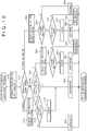
- FIGS. 10 and 11 flow charts of the device assignment process in the login process 2 are depicted in FIGS. 10 and 11 .
- an assignment technique of one inputting device is indicated. It is to be noted that whether a main device or a sub device is to be assigned may be determined by referring to an apparatus ID and a definition file described hereinabove.
- FIG. 10 depicts a flow chart of a main device assignment process.
- a main device which is not assigned as yet is connected to the information processing apparatus 10 (S10).
- the assignment processing unit 136 acquires the number of login users by referring to the storage substance of the login user storage unit 134 (S12). It is to be noted that, although the login person number may be acquired by counting the number of login users in the login user storage unit 134, the count value of the login person number may be stored in the login user storage unit 134.
- the assignment processing unit 136 sends a generation instruction of a user selection screen image to the selection screen image generation unit 138, and the selection screen image generation unit 138 causes the outputting apparatus 4 to display a user selection screen image ( FIG. 6(a) ) (S14). If the user does not select the user specification information on the user selection screen image but operates the cancel button (N at S16), then the connection between the main device and the information processing apparatus 10 is disconnected (S20). It is to be noted that, although it is assumed that the main device is connected by wireless connection, where the main device is connected by a USB cable, the main device may be managed as a device in a "standby state" described in connection with FIG. 11 .
- the login processing unit 132 causes the user A to log in to the information processing apparatus 10 (S18). It is to be noted that, where a login passcode is set, the login processing unit 132 causes the outputting apparatus 4 to display an inputting screen (refer to FIG. 6(b) ) of a passcode and performs user authorization using the inputted passcode to allow the user A to log in.
- the assignment processing unit 136 assigns the main device to the user A (S24) and ends the assignment process. It is to be noted that, while the processing advances, after the login process at S18 in FIG. 10 , directly to the assignment process at step S24, since the login person number has changed from zero to one, the processing may return to the step of S12 after the login process at S18.
- the assignment processing unit 136 decides whether a main device of the same type is assigned already to the login user (user A) by referring to the apparatus ID of the non-assigned main device (S22). For example, when the game controller 6a is assigned to the user A, if the inputting device connected newly is a joystick, then the assignment processing unit 136 decides that a main device of the same type is not assigned (N at S22) and assigns the joystick to the user A (S24), whereafter the assignment processing unit 136 ends the assignment process.
- the assignment processing unit 136 decides that a main device of the same type is assigned already (Y at S22).
- the assignment processing unit 136 sends a generation instruction of a user selection screen image to the selection screen image generation unit 138, and the selection screen image generation unit 138 causes the outputting apparatus 4 to display a user selection screen image (S26).
- this user selection screen image may be same as the user selection screen image depicted in FIG. 6(a)
- the user selection screen image may be a result of deletion of the user specification information of the user A from the user selection screen image depicted in FIG. 6(a) . If the user does not select user specification information on the user selection screen image but operates the cancel button (N at S28), then the connection between the main device and the information processing apparatus 10 is disconnected (S34).
- the login processing unit 132 allows the user B to log in to the information processing apparatus 10 (S30).
- the assignment processing unit 136 assigns the main device (in this case, the game controller 6b) to the user B (S32) and ends the assignment process.
- the assignment processing unit 136 sends a generation instruction of a user selection screen image to the selection screen image generation unit 138, and the selection screen image generation unit 138 causes the outputting apparatus 4 to display a user selection screen image (S36).
- a user selection screen image is displayed by the selection screen image generation unit 138. If the user does not select the user specification information on the user selection screen image but operates the cancel button (N at S38), then the connection between the main device and the information processing apparatus 10 is disconnected (S48).
- the login processing unit 132 decides whether or not the selected user is a login user (S40). When the user A and the user B are login users, if the selected user is the user A or the user B (N at S40), then the login process is not performed, and the assignment processing unit 136 assigns the main device to the selected user A or user B (S46). On the other hand, if the selected user is not a login user but is the user C who does not log in (Y at S40), then the login processing unit 132 allows the user C to log in to the information processing apparatus 10 (S42). The assignment processing unit 136 assigns the main device to the user C (S44) and ends the assignment process.
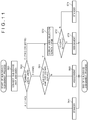
- FIG. 11 depicts a flow chart of a sub device assignment process.
- a sub device which is not assigned as yet is first connected to the information processing apparatus 10 (S60).
- the sub device which is not assigned includes a sub device which has been connected by a USB cable since before the main power supply to the information processing apparatus 10 is turned on and a sub device into which a USB cable is inserted after the main power supply to the information processing apparatus 10 is turned on.
- the assignment processing unit 136 acquires the number of users who log in by referring to the stored substance of the login user storage unit 134 (S62).
- the login process is not activated. Accordingly, even if a sub device which is not assigned as yet is connected, when the login user number is zero (A at S62), the assignment processing unit 136 manages the sub device as a device in a state in which the assignment processing unit 136 waits for an assignment process (S64). This state of the sub device is hereinafter referred to as "standby state.”
- the assignment processing unit 136 decides whether a sub device of the same type is assigned already to the login user (user A) by referring to the apparatus ID of the not-assigned sub device (S66). For example, where a keyboard is assigned already to the user A, if the inputted device connected newly is a headset, then the assignment processing unit 136 decides that a sub device of the same type is not assigned (N at S66) and assigns the headset to the user A (S68), whereafter the assignment process is ended. On the other hand, where a keyboard is assigned already to the user A, if the inputting device connected newly is a keyboard of the same type, then the assignment processing unit 136 decides that a sub device of the same type is assigned already (Y at S66).
- the assignment processing unit 136 sends a generation instruction of a user selection screen image to the selection screen image generation unit 138, and the selection screen image generation unit 138 causes the outputting apparatus 4 to display a user selection screen image (S70).
- a user for example, the user C
- the assignment processing unit 136 assigns the sub device to the user C who is not a login user (S72).
- This assignment information is stored in an associated relationship with the user account of the user C, who is a non-login user, into the login user storage unit 134. It is to be noted that, if the user C thereafter logs in, then the login status of the user C in the login user storage unit 134 is changed from non-login to login.
- the sub device is managed as a device in a standby state (S74). It is to be noted that, in an ordinary utilization scene, it is supposed that the user may operate the cancel button at S72.
- the assignment processing unit 136 sends a generation instruction of a user selection screen image to the selection screen image generation unit 138, and the selection screen image generation unit 138 causes the outputting apparatus 4 to display a user selection screen image (S70).
- the selection screen image generation unit 138 causes a user selection screen image to be displayed.
- the sub device is managed as a sub device in a standby state (S74). However, if the user selects the user specification information on the user selection screen image (Y at S72), then the assignment processing unit 136 assigns the sub device to the selected user (S76), whereafter the assignment process is ended.
- the assignment process of an inputting device when the number of login users increases has been described.
- the number of login users decreases namely, when a login user logs out
- the inputting device having been assigned to the user who has logged out is managed as an inputting device in a standby state.
- the assignment processing unit 136 may automatically assign the inputting device, which has been placed into a non-assigned state, to a remaining login user.
- a sub device is connected to the information processing apparatus 10 by a USB cable
- a sub device may be connected to the information processing apparatus 10 by wireless connection or a main device may be connected to the information processing apparatus 10 by a USB cable.
- the assignment processing unit 136 performs different assignment processes between a case in which one login user exists and another case in which two or more login users exist.
- the assignment processing unit 136 automatically assigns, to the user, an inputting device connected already upon login of the user or an inputting device connected newly after login.
- the assignment processing unit 136 instructs the selection screen image generation unit 138 to generate a user selection screen image and causes the user to declare use of the inputting device.
- the assignment processing unit 136 does not automatically assign the inputting device but may issue a confirmation message regarding whether the inputting device may be assigned to the login user.
- the assignment processing unit 136 detects a non-assigned inputting device, then the assignment processing unit 136 causes the outputting apparatus 4 to display a message of "May the inputting device be assigned to you" such that the assignment process is performed by depression of the OK button by the user. Also in this case, it is not necessary for the user to perform a work for selecting the user itself from within the user selection screen image, but only it is necessary for the user to merely depress an inputting unit (for example, the o button 72) associated with the OK button on the game controller 6. Therefore, only a simple and easy assignment work is required.
- an inputting unit for example, the o button 72
- a definition file for an application which prescribes whether each of a plurality of types of inputting devices is a main device or a sub device may be referred to to determine whether the inputting device is a main device or a sub device.
- This definition file may be prepared for each application. Where such definition files are not prepared for all applications, only if a definition file is prepared, the definition file for the application is referred to, but if a definition file is not prepared, then a default definition file described hereinabove may be referred to.
- the present invention can be utilized in a technology for assigning an inputting device to a user.
Landscapes
- Engineering & Computer Science (AREA)
- Multimedia (AREA)
- Human Computer Interaction (AREA)
- Theoretical Computer Science (AREA)
- Computer Security & Cryptography (AREA)
- General Engineering & Computer Science (AREA)
- General Physics & Mathematics (AREA)
- Physics & Mathematics (AREA)
- Computer Hardware Design (AREA)
- Software Systems (AREA)
- Business, Economics & Management (AREA)
- General Business, Economics & Management (AREA)
- Computer Networks & Wireless Communication (AREA)
- User Interface Of Digital Computer (AREA)
Abstract
Description
- The present invention relates to a technology for assigning an inputting device to a user in an information processing apparatus.
- A game apparatus advances a game on the basis of operation information of a game controller operated by a user. In recent years, various inputting devices including not only a game controller but also a keyboard and so forth are connected to a game apparatus such that the user can provide a variety of operation information of the inputting devices to the game apparatus.
- In a game apparatus to which a plurality of users can log in at the same time, it is necessary for the game apparatus to grasp to which user a used inputting device is assigned. As one simple technique, every time an inputting device is connected to the game apparatus, the game apparatus may inquire a user about who will use the inputting device. In this case, by declaring that the user itself uses the inputting device to the game apparatus, the game apparatus assigns the inputting device to the declaring user and, as a result, the game apparatus can recognize that operation information from the inputting device originates from the declaring user.
- According to this technique, since the user itself declares use of the inputting device, the game apparatus can link the inputting device and the user to each other with certainty, and it can be considered that the technique is an effective technique. However, in a game apparatus in which one user can use plural kinds of inputting devices, the user receives an inquiry every time an inputting device is connected to the game apparatus, and some user may feel the linkage work cumbersome. Therefore, development of a technology for suitably assigning an inputting device connected to a game apparatus to a user is demanded.
- It is to be noted that such needs as described above exist not only for a game apparatus but also for other information processing apparatus to which a plurality of users can log in at the same time, and also in such information processing apparatus, it is preferable for an inputting device to be suitably assigned to a user.
- Therefore, it is an object of the present invention to provide a technology for suitably assigning an inputting device to a user.
- In order to solve the problem described above, according to an aspect of the present invention, an information processing apparatus includes an assignment processing unit configured to assign an inputting device to a user who is in a login state, and an accepting unit configured to accept an input from the inputting device. The assignment processing unit controls an assignment process of the inputting device in response to a number of users who are in the login state.
- According to another aspect of the present invention, a method for assigning an inputting device to a user includes controlling an assignment process of an inputting device in response to the number of users who are in a login state.
- It is to be noted that arbitrary combinations of the components described above and conversions of the representation of the present invention between arbitrary ones of a method, an apparatus, a system, a recording medium a computer program and so forth are effective as modes of the present invention.
-
- [
FIG. 1 ]
FIG. 1 is a view depicting an information processing system according to an embodiment of the present invention. - [
FIG. 2 ]
FIG. 2(a) is a view depicting an appearance configuration of an upper face of a game controller, andFIG. 2(b) is a view depicting an appearance configuration of a side face on the far side of the game controller. - [
FIG. 3 ]
FIG. 3 is a view depicting an internal configuration of the game controller. - [
FIG. 4 ]
FIG. 4 is a view depicting functional blocks of an information processing apparatus. - [
FIG. 5 ]
FIG. 5 is a view depicting an internal configuration of the information processing apparatus. - [
FIG. 6 ]
FIG. 6(a) is a view depicting an example of a user selection screen image, andFIG. 6(b) is a view depicting an example of a passcode inputting screen image. - [
FIG. 7 ]
FIG. 7 is a view depicting a login screen image including a face frame. - [
FIG. 8 ]
FIG. 8 is a view depicting a login screen image in which a user has placed the face in the face frame. - [
FIG. 9 ]
FIG. 9 is a view depicting another example of a user selection screen image. - [
FIG. 10 ]
FIG. 10 is a view illustrating a processing flow of main device assignment control. - [
FIG. 11 ]
FIG. 11 is a view illustrating a processing flow of sub device assignment control. -
FIG. 1 depicts aninformation processing system 1 according to an embodiment of the present invention. Theinformation processing system 1 includes aninformation processing apparatus 10 which is a user terminal, and aserver 5. An access point (hereinafter referred to as "AP") 8 has functions of a wireless access point and a router, and theinformation processing apparatus 10 connects to theaccess point 8 by wireless connection or wire connection and connects theserver 5 on anetwork 3 for communication. - An
auxiliary storage apparatus 2 is a mass storage apparatus such as an HDD (hard disk drive) or a flash memory and may be an external storage apparatus which is connected to theinformation processing apparatus 10 by a USB (universal serial bus) or the like or may be a built-in storage apparatus. Anoutputting apparatus 4 may be a television set having a display unit which outputs an image and a speaker which outputs sound or may be a computer display unit. Theinformation processing apparatus 10 is connected to agame controller 6, which is operated by a user, by wireless connection or wire connection, and thegame controller 6 outputs an operation signal representative of a result of an operation by the user to theinformation processing apparatus 10. If theinformation processing apparatus 10 accepts an operation signal from thegame controller 6, then it reflects the operation on processing of an OS (system software) or an application and outputs a result of processing from theoutputting apparatus 4. Thegame controller 6 includes a plurality of inputting units such as a plurality of push-type operation buttons, an analog stick capable of inputting an analog amount and a rotary button. In the present embodiment, theinformation processing apparatus 10 may be a game apparatus which executes a game program, and thegame controller 6 may be an inputting device which provides operation information of a user to the game apparatus. - In the
information processing system 1, thegame controller 6 is an example of an inputting device for inputting operation information to theinformation processing apparatus 10. As a different example of an inputting device, a device similar to thegame controller 6 for providing operation information to a game program in order that the user may play a game is available. Thegame controller 6 and a device similar to thegame controller 6 are each referred to as "main device" herein, and the user can play a game by using the main device singly. - Further, as another example of an inputting device, also a device used auxiliarily when the user plays a game using a main device is available. For example, as a different example of the inputting device, a device such as a keyboard, a mouse or a headset is available and is a device to be used auxiliarily during a game play assuming the presence of a main device. For example, a keyboard is used to input a message for some other user having a connection to the
network 3 during a game play. Similarly, a headset with a microphone is used for communicating with some other user during a game play. Such devices as just described are different from the main device and are not used for operation of a game character but are used auxiliarily to the end. In the present specification, such a device as just described is referred to as "sub device." - It is to be noted that, supplementing a relationship between the main device and the sub device, a game program may accept not only an input from the main device but also an input from the sub device to advance a game. Also in this case, the game program operates supposing that the user operates the main device, and is capable of operating without the sub device. Conversely speaking, the game program does not operate only with operation information from the sub device, and, in this sense, an inputting device which by itself can cause a game to operate may be defined as the main device and an inputting device capable of being used together with the main device may be defined as sub device. In the
information processing apparatus 10, a definition file in which attribute information which defines whether each of plural kinds of inputting devices capable of being connected to theinformation processing apparatus 10 is a main device or a sub device in advance is recorded is retained. It is to be noted that the definition file can be updated and, for example, if a game capable of operating only by an input from a headset with a microphone is developed, then the definition file may be updated, for example, by system update such that the headset is managed as the main device. - In the
information processing apparatus 10 of the present embodiment, the main device and the sub device are inputting devices to be assigned to login users. It is to be noted that inputting devices which cannot be assigned to a login user exist from among inputting devices, and one of such inputting devices is acamera 7 for inputting a picked up image to theinformation processing apparatus 10. - The
camera 7 which is an image pickup apparatus is provided in the proximity of theoutputting apparatus 4 and picks up an image of a space around the outputtingapparatus 4. While an example is depicted inFIG. 1 in which thecamera 7 is attached to an upper portion of theoutputting apparatus 4, thecamera 7 may be disposed at a side portion or a lower portion of theoutputting apparatus 4, and, in any event, thecamera 7 is disposed at a position at which an image of the user positioned in front of theoutputting apparatus 4 can be picked up. Thecamera 7 may be a stereo camera. - The
server 5 provides a network service to a user of theinformation processing system 1. Theserver 5 manages a network account for specifying each user, and each user uses its network account to sign in to a network service provided by theserver 5. The user can register save data of a game or a trophy which is a virtual award article acquired during game play into theserver 5 by signing in to the network service from theinformation processing apparatus 10. Further, the user can be connected to another user via thenetwork 3 to send or receive chat messages and voice messages. - A button configuration of the
game controller 6 as an example of the inputting device is described below. -
FIG. 2(a) depicts an appearance configuration of the upper face of the game controller. The user would grasp a leftside grip portion 78b with the left hand thereof and grasp a rightside grip portion 78a with the right hand thereof to operate thegame controller 6. On an upper face of a housing of thegame controller 6, a direction key 71, analog sticks 77a and 77b and fourdifferent operation buttons 76 which are inputting units are provided. The fourdifferent buttons 72 to 75 have different figures in different colors in order to allow distinction among them. In particular, on theo button 72, a red round mark is inscribed; on thex button 73, a blue cross mark is inscribed; on the □button 74, a purple square mark is inscribed; and on theΔ mark 75, a green triangular mark is inscribed. Atouch pad 79 is provided at a flat region between the direction key 71 andoperation buttons 76 on the upper face of the housing. Thetouch pad 79 also functions as a press-type button which is depressed down when the user pushes and comes back to the original position when the user releases its hand. - A
function button 80 is provided between the twoanalog sticks function button 80 is used to switch on the power supply to thegame controller 6 and simultaneously activate a communication function for connecting thegame controller 6 and theinformation processing apparatus 10 to each other. If thegame controller 6 is newly connected, then theinformation processing apparatus 10 executes a login process of a user. It is to be noted that, when the main power supply to theinformation processing apparatus 10 is off, if thefunction button 80 is depressed, then theinformation processing apparatus 10 accepts a connection request transmitted thereto from thegame controller 6 as an instruction for switching on the main power supply. As a result, after the main power supply to theinformation processing apparatus 10 is switched on, theinformation processing apparatus 10 executes a login process of a user. - A
SHARE button 81 is provided between thetouch pad 79 and the direction key 71. TheSHARE button 81 is utilized to input an instruction from the user to the OS or system software of theinformation processing apparatus 10. Meanwhile, anOPTIONS button 82 is provided between thetouch pad 79 and theoperation buttons 76. TheOPTIONS button 82 is utilized to input an instruction from the user to an application (game) executed in theinformation processing apparatus 10. Both of theSHARE button 81 and theOPTIONS button 82 may be formed as push-type buttons. -
FIG. 2(b) depicts an appearance configuration of the back side face of the game controller. On the upper side of the back side face of the housing of thegame controller 6, thetouch pad 79 is provided so as to extend from the upper face of the housing, and a transversely elongatedlight emitting section 85 is provided on the lower side of the back side face of the housing. Thelight emitting section 85 has red (R), green (G) and blue (B) LEDs (light emitting diodes), which are turned on in accordance with emission color information transmitted thereto from theinformation processing apparatus 10. Where twogame controllers 6a and 6b are used as depicted inFIG. 1 , theinformation processing apparatus 10 may determine the lighting colors of thelight emitting sections 85 of thegame controllers 6a and 6b to different colors, to red and green, so that the users A and B can distinguish therespective game controller 6. Consequently, since each user can recognize thegame controller 6 used by the user itself from the lighting color of thelight emitting section 85, the possibility that thegame controller 6 may be mistaken decreases. - On the housing back side face, an
upper side button 83a and alower side button 84a as well as anupper side button 83b and alower side button 84b are provided at leftwardly and rightwardly symmetrical positions in the longitudinal direction. Theupper side button 83a and thelower side button 84a are operated by the forefinger and the middle finger of the right hand of the user, respectively, and theupper side button 83b and thelower side button 84b are operated by the forefinger and the middle filter of the left hand of the user, respectively. Since thelight emitting section 85 is provided between the arrangement of theupper side button 83a and thelower side button 84a on the right side and the arrangement of theupper side button 83b and thelower side button 84b on the left side as depicted inFIG. 2(b) , it is not hidden by any of the fingers which operate associated buttons, and thecamera 7 can suitably pick up an image of thelight emitting section 85 which is in an on state. The upper side buttons 83 may be configured as push-type buttons, and the lower side buttons 84 may be configured as trigger-type buttons supported for turning motion. -
FIG. 3 depicts a configuration of thegame controller 6. Thegame controller 6 includes awireless communication module 90, aprocessing section 91, thelight emitting section 85, and avibrator 98. Thewireless communication module 90 has a function of transmitting and receiving data to and from a wireless communication module of theinformation processing apparatus 10. Theprocessing section 91 executes an intended process of thegame controller 6. - The
processing section 91 has a main controllingunit 92, aninput acceptance unit 93, a lightemission controlling unit 94, a three-axis acceleration sensor 95, a three-axis gyro sensor 96 and adriving controlling unit 97. The main controllingunit 92 carries out transmission and reception of necessary data to and from thewireless communication module 90. - The
input acceptance unit 93 accepts input information from such inputting units as the direction key 71,operation buttons 76, analog sticks 77,touch pad 79,function button 80,SHARE button 81,OPTION button 82, upper side buttons 83 and lower side buttons 84 and sends the input information to the main controllingunit 92. The main controllingunit 92 converts the received input information into a predetermined control signal as occasion demands and supplies the control signal to thewireless communication module 90. Thus, thewireless communication module 90 sends the control signal to theinformation processing apparatus 10 at a predetermined timing. The lightemission controlling unit 94 controls emission of light from ared LED 87, agreen LED 88 and ablue LED 89 which configure thelight emitting section 85. - In the
information processing system 1 of the present embodiment, if the user depresses thefunction button 80 while thegame controller 6 is in a power-off state, then the power supply to thegame controller 6 is turned on and the main controllingunit 92 generates a connection request to theinformation processing apparatus 10. Thewireless communication module 90 transmits the connection request to theinformation processing apparatus 10. At this time, even if theinformation processing apparatus 10 is in a main power supply off state, since the wireless communication module in theinformation processing apparatus 10 is in an active state even in the main power supply off state, theinformation processing apparatus 10 turns on the main power supply in response to reception of the connection request thereby to start up the OS (system software) to establish wireless connection to thegame controller 6. After the wireless connection to thegame controller 6 is established, theinformation processing apparatus 10 executes a login process of a user. - The system software of the
information processing apparatus 10 determines a lighting color of thelight emitting section 85 of thegame controller 6 from which the connection request has been received and transmits the lighting color information to thegame controller 6. At this time, the system software preferably analyzes the color information included in the space whose image is picked up by thecamera 7 and specifies colors which are not included in environment colors as far as possible to determine a lighting color of thelight emitting section 85. This makes it possible to suitably detect thelight emitting section 85 which is to be turned on with the designated light color from the picked up image of thecamera 7 after thelight emitting section 85 is turned on. An image picked up by thecamera 7 may be provided to theinformation processing apparatus 10 such that a result of detection of a movement of thegame controller 6 or of the user is utilized for game advancement. Accordingly, thecamera 7 functions as an inputting device to theinformation processing apparatus 10. - The lighting color information received by the
wireless communication module 90 is passed to the main controllingunit 92, and the main controllingunit 92 notifies the lightemission controlling unit 94 of the lighting color information. Consequently, the lightemission controlling unit 94 can control thelight emitting section 85 to emit light with the designated lighting color. - The
vibrator 98 is configured including an eccentric motor and so forth and is driven by thedriving controlling unit 97. The three-axis acceleration sensor 95 detects acceleration components in the three-axis directions of the XYZ directions of thegame controller 6, and the three-axis gyro sensor 96 detects angular velocities in an XZ plane, a ZY plane and a YX plane. -
FIG. 4 depicts a functional block diagram of theinformation processing apparatus 10. Theinformation processing apparatus 10 is configured from a mainpower supply button 20, a power supply ONLED 21, astandby LED 22, asystem controller 24, aclock 26, adevice controller 30, amedia drive 32, aUSB module 34, aflash memory 36, awireless communication module 38, awire communication module 40, asub system 50 and amain system 60. - The
main system 60 includes a main CPU (central processing unit), a memory and a memory controller which are main storage apparatuses, a GPU (graphics processing unit) and so forth. The GPU is utilized principally for arithmetic operation processing of a game program. The functions mentioned are configured as a system-on-chip on a single chip. The main CPU starts up the OS and has a function of executing an application installed in theauxiliary storage apparatus 2 under an environment provided by the OS. - The
sub system 50 includes a sub CPU, a memory and a memory controller which are main storage apparatuses, and so forth, but does not include a GPU. The number of circuit gates of the sub CPU is smaller than that of the main CPU, and the operation power consumption of the sub CPU is lower than that of the main CPU. The sub CPU operates while the main CPU is in a standby state as described hereinabove, and the processing functions of the sub CPU are restricted in order to suppress the power consumption low. It is to be noted that the sub CPU and the memory may be formed on different chips from each other. - The main
power supply button 20 is an inputting unit to which operation inputting is carried out by the user and is provided on a front face of the housing of theinformation processing apparatus 10. The mainpower supply button 20 is operated to turn on or off the power supply to themain system 60 of theinformation processing apparatus 10. In the following description, that the main power supply is in an on state signifies that themain system 60 is in an active state, and that the main power supply is in an off state signifies that themain system 60 is in a standby state. The power supply ONLED 21 is turned on when the mainpower supply button 20 is turned on, and thestandby LED 22 is turned on when the mainpower supply button 20 is turned off. - The
system controller 24 detects depression of the mainpower supply button 20 by the user. If the mainpower supply button 20 is depressed when the main power supply is in an off state, then thesystem controller 24 acquires the depression operation as an "on instruction." However, if the mainpower supply button 20 is depressed when the main power supply is in an on state, then thesystem controller 24 acquires the depression operation as an "off instruction." After thesystem controller 24 acquires the on instruction, themain system 60 executes a login process of a user. - The main CPU has a function of executing a game program installed in the
auxiliary storage apparatus 2 or a ROM (read-only memory)medium 44 while the sub CPU does not have such a function as just described. However, the sub CPU has a function of accessing theauxiliary storage apparatus 2 and a function of transmitting and receiving data to and from theserver 5. The sub CPU is configured so as to have only such restricted processing functions and therefore can operate with low power consumption in comparison with the main CPU. The functions of the sub CPU are executed while the main CPU is in a standby state. Since thesub system 50 is operative when themain system 60 is in a standby state, theinformation processing apparatus 10 normally maintains a sign-in state in the network service provided by theserver 5. - The
clock 26 is a real time clock and generates and supplies date and time information at present to thesystem controller 24,sub system 50 andmain system 60. - The
device controller 30 is configured as an LSI (large-scale integrated circuit) which executes transfer of information between devices like a south bridge. As depicted inFIG. 4 , to thedevice controller 30, such devices assystem controller 24, media drive 32,USB module 34,flash memory 36,wireless communication module 38,wire communication module 40,sub system 50 andmain system 60 are connected. Thedevice controller 30 absorbs differences in electric characteristics of and differences in data transfer speed between the devices to control timings of data transfer. - The media drive 32 is a drive apparatus which drives, when a
ROM medium 44 in which application software of a game and so forth and license information are recorded is loaded in themedia drive 32, theROM medium 44 and reads out a program, data and so forth from theROM medium 44. TheROM medium 44 is a read-only recording medium such as an optical disk, a magneto-optical disk or a Blu-ray disk. - The
USB module 34 is a module for connecting to an external apparatus by a USB cable. TheUSB module 34 connects to theauxiliary storage apparatus 2 and thecamera 7 through a USB cable. It is to be noted that, though not depicted, theUSB module 34 may be connected to an inputting device such as a main device or a sub device other than thegame controller 6 through a USB cable. Such inputting devices as described above are connected to theinformation processing apparatus 10 by the user inserting a USB terminal thereof into theUSB module 34 when the user is to use the inputting device. It is to be noted that the inputting devices described above are sometimes left connected to theUSB module 34 through a USB cable after the user logs out. Theinformation processing apparatus 10 of the present embodiment has a function for suitably assigning an inputting device normally connected to theUSB module 34 or an inputting device newly connected after login of the user to the user. - The
flash memory 36 is an auxiliary storage device which configures an internal storage. Thewireless communication module 38 communicates by wireless communication, for example, with thegame controller 6 by a communication protocol such as the Bluetooth (registered trademark) protocol or the IEEE (institute of electrical and electronic engineers) 802.11 protocol. It is to be noted that thewireless communication module 38 may be compatible with a third generation digital portable telephone system in compliance with the IMP-2000 (international mobile telecommunication 2000) prescribed by the ITU (international telecommunication union). Alternatively, thewireless communication module 38 may be compatible with a digital portable telephone system of a further different generation. Thewire communication module 40 communicates by wireless communication with an external apparatus and connects to thenetwork 3, for example, through theaccess point 8. - Plural kinds of login processes are prepared for the
information processing apparatus 10 of the present embodiment and, if a login request is issued from a user, then theinformation processing apparatus 10 determines one login process to be executed in accordance with system setting. Outline of three kinds of representative login processes in theinformation processing apparatus 10 is described below. - A
login process 1 is a process for automatically allowing a user to log in when theinformation processing apparatus 10 has setting for automatic login of one user. In thelogin process 1, the user with regard to which setting of automatic login is provided is caused to log in just after theinformation processing apparatus 10 is started up or just after theinformation processing apparatus 10 resumes from a system suspended state. For example, in such a case that the user is in a single life and there normally is no other user to log in, if setting for automatic login is established, then the user can automatically log in without the intervention of a user selection screen in alogin process 2 hereinafter described in response to an on operation of the mainpower supply button 20 in a state in which the main power supply to theinformation processing apparatus 10 is off. It is to be noted that thelogin process 1 is executed when there is no login user, but thelogin process 1 is not executed if there is a user who logs in already. - Two kinds of login processes described below are executed when there is no setting for automatic login. Between the two login processes, the
login process 2 is executed when setting of face authorization login is not available, and thelogin process 3 is executed when setting for face authorization login is available. - The
login process 2 is a process for allowing login of a user selected on a user selection screen image displayed on theoutputting apparatus 4. In thelogin process 2, if a user operates thefunction button 80 of thegame controller 6 to transmit a login request to theinformation processing apparatus 10, then theinformation processing apparatus 10 displays a user selection screen image on theoutputting apparatus 4. Then, if the user operates thegame controller 6 to select an own icon in the user selection screen image and input a passcode for login as occasion demands, then theinformation processing apparatus 10 performs user authorization to allow the user to log in. It is to be noted that the icon which makes a selection target is exemplary, and the target to be selected by the user may be information for specifying the user itself, for example, a user name displayed by a text, a photograph of the user or the like. - The
login process 3 is a process which allows a user to log in when a face authorization of the user is performed utilizing a picked up image by thecamera 7 and the detected face image coincides with the face of the user registered in theinformation processing apparatus 10. In thelogin process 3, if the user depresses the mainpower supply button 20 or thegame controller 6 is connected to theinformation processing apparatus 10, then theinformation processing apparatus 10 performs face authorization of the user included in a picked up image and urges the user to operate a predetermined action to allow the user to log in. - While the login processes described above are representative login processes, also some other login process is prepared in the
information processing apparatus 10. If the mainpower supply button 20 is depressed where setting for automatic login and setting for face authorization login are not available in theinformation processing apparatus 10 and besides no one logs in, then theinformation processing apparatus 10 may cause a user selection screen image to be displayed on theoutputting apparatus 4. Besides, where setting for face authorization login is available and a login request is generated in response to an operation of thefunction button 80, face authorization of the user may be performed on the background while a user selection screen image is displayed on theoutputting apparatus 4 by theinformation processing apparatus 10. It is to be noted that, if face authorization cannot be performed within a predetermined time period in thelogin process 3, then a user selection screen image may be displayed on theoutputting apparatus 4. -
FIG. 5 depicts an internal configuration of theinformation processing apparatus 10. Theinformation processing apparatus 10 includes acommunication unit 102, aninput acceptance unit 104, animage acquisition unit 106, amicrophone 108, amanagement unit 100 and a registered userinformation retention unit 150. Theinput acceptance unit 104 has a function of accepting an input from the user, for example, an input from an inputting device. The function of themanagement unit 100 is implemented by an OS (system software) of theinformation processing apparatus 10 and an application executed by the OS or a memory, and includes a light emissioncolor determination unit 110, aprocess determination unit 120 and alogin controlling unit 130. - The
login controlling unit 130 includes alogin processing unit 132, a loginuser storage unit 134, anassignment processing unit 136 and a selectionimage generation unit 138. Thelogin processing unit 132 has a function of performing a login process of a user, and theassignment processing unit 136 has a function of assigning an inputting device to a user. If an inputting device connected to theinformation processing apparatus 10 is assigned to a user by theassignment processing unit 136, then theinformation processing apparatus 10 can decide by which user an input from the inputting device is performed. It is to be noted that, as the inputting device, an inputting device capable of being assigned to a login user and another inputting device capable of being not assigned to a login user are available, and an inputting device to be assigned to a login user by theassignment processing unit 136 is at least one of main devices such as a game controller and a joystick and sub devices such as a headset. The inputting device capable of being not assigned to the user is thecamera 7. It is to be noted that a single microphone and a headphone without a microphone may be handled as an inputting device not to be assigned to the login user. The selectionimage generation unit 138 generates a user selection screen image which allows selection of a user and causes theoutputting apparatus 4 to display the generated screen image. Thecommunication unit 102 exhibits the functions of thewireless communication module 38 andwire communication module 40 depicted inFIG. 4 . Themicrophone 108 may be such as provided on a headset which is a sub device. - The components depicted as functional blocks for performing various processes in
FIG. 5 can be configured, in hardware, from circuit blocks, a memory and some other LSIs and are implemented, in software, by a program loaded in the memory or the like. Accordingly, it is understood by those skilled in the art that the functional blocks can be implemented in various modes such as only from hardware, only from software or from a combination of hardware and software, and are not limited to only one of the various modes. - According to the
information processing apparatus 10 of the present embodiment, also a function for suitably assigning an inputting device to a user is one of characteristics in addition to a function for supporting login operation of a user. In order to log in to the OS of theinformation processing apparatus 10, as a premise therefor, it is necessary for a user to acquire a user account in advance and register various kinds of user information in theinformation processing apparatus 10. A user who has a registration of a user account in theinformation processing apparatus 10 is hereinafter referred to sometimes as "registered user." Theinformation processing apparatus 10 is an apparatus to which a plurality of registered users can log in at the same time and, if a plurality of users log in at the same time, then theinformation processing apparatus 10 can store save data of the users individually. - The registered user
information retention unit 150 retains various kinds of information relating to registered users and particularly retains, in an associated relationship of a user account, a login passcode, a sign-in ID (identification) for signing in to theserver 5, a network account, an online ID of a user, a user icon for representation of the user and so forth as registered user information. It is to be noted that, regarding a registered user who has a registration of a face image in advance for a face authorization process, the registered userinformation retention unit 150 retains face identification data as the registered user information in an associated relationship with the user account. - Here, while the face identification data is characteristic amount data of a face image of the registered user, the face identification data may be face image data itself. The face identification data is data used as a comparison target in the face recognition process by the
login processing unit 132, and is generated in accordance with a face recognition algorithm adopted by thelogin processing unit 132. For example, the face identification data may be data obtained by extracting a relative position or a size of parts of the face and shapes of the eyes, nose, cheek bones and chin as characteristics. Further, the face identification data may be data obtained by extracting difference data from standard data of a face image. What face identification data is to be extracted is determined depending upon a face recognition algorithm adopted by thelogin processing unit 132. It is to be noted that, regarding a registered user who does not have a registration of a face image, naturally face identification data is not included in the registered userinformation retention unit 150. - In the present embodiment, registered user information of a user A (online ID is "HANAKO"), a user B (online ID is "SACHIKO") and some other user is stored in the registered user
information retention unit 150. A process for assigning an inputting device to a user upon and after login of a registered user is described below. - As described already, a main device is a device for progressing an application such as a game to be executed by the
information processing apparatus 10 and includes thegame controller 6 and an inputting device similar to thegame controller 6. For example, as an inputting device similar to thegame controller 6, a joystick, a controller for exclusive use for a specific game such as a handle controller used in a car race game are available. Further, a sub device is a device used auxiliarily by a user during execution of an application and includes an inputting device such as a keyboard, a mouse or a headset. Theassignment processing unit 136 has a function of controlling an assignment process of an inputting device in response to the number of users having logged in already. An apparatus ID is set to each of the inputting devices, and theassignment processing unit 136 specifies the type of the inputting device from the apparatus ID of the inputting device. In the example described above, the type of the inputting device indicates one of a game controller, a joystick, a handle controller, a keyboard, a mouse and a headset. - An assignment process of a device in the representative login processes 1 to 3 is described below. It is to be noted that a device assignment process for a user who logs in at first in a state in which there is no login user is described below.
- As described above, the
login process 1 is executed in the case where one registered user is set as an automatic login user and there is no user who logs in already. Where setting for automatic login is available in theinformation processing apparatus 10, theprocess determination unit 120 determines thelogin process 1 as a login process to be executed and thelogin controlling unit 130 executes thelogin process 1. - If an on operation of the main
power supply button 20 of theinformation processing apparatus 10 is performed in a state in which the main power supply to theinformation processing apparatus 10 is off, then theinput acceptance unit 104 accepts a login request and thelogin processing unit 132 allows the user, who is set for automatic login, to log in to theinformation processing apparatus 10. For example, if the user A is set as a target of automatic login, then thelogin processing unit 132 causes the user A to log in. In this manner, thelogin process 1 is executed when theinput acceptance unit 104 accepts a login request in a state in which automatic login setting is available and beside there is no login user. Thelogin processing unit 132 stores login information, namely, information for specifying the user A (user account), into the loginuser storage unit 134. - After the
login processing unit 132 causes the user A to log in, theassignment processing unit 136 assigns an inputting device connected to theinformation processing apparatus 10 to the login user. After the inputting device is assigned to the login user, theassignment processing unit 136 stores the apparatus ID of the inputting device in an associated relationship with the user account into the loginuser storage unit 134. - If a main device such as the
game controller 6 is connected to theinformation processing apparatus 10 in a state in which only the user A logs in, then theassignment processing unit 136 automatically assigns the connected main device to the user A. On the other hand, if a sub device such as the keyboard is connected to theinformation processing apparatus 10 in a state in which only the user A logs in, then theassignment processing unit 136 automatically assigns the connected sub device to the user A. - It is to be noted that, where an inputting device is normally connected to the
USB module 34 through a USB cable, if the main power supply to theinformation processing apparatus 10 is turned on, then a USB device linked by a USB cable is recognized by theinformation processing apparatus 10 and is placed in a connected state. If the user A automatically logs in thereafter, then theassignment processing unit 136 retrospectively assigns the inputting device to the user A. In this manner, if a new inputting device is connected to theinformation processing apparatus 10 after one user logs in or if there exists an inputting device which is not assigned to any user at a time point at which one user logs in, then theassignment processing unit 136 assigns the inputting device to the login user. - If a device of a type similar to that of the device assigned to the login user already is connected to the
information processing apparatus 10, then theassignment processing unit 136 does not assign the device of the same type to the same login user. For example, if one game controller 6a is assigned to the user A, then when adifferent game controller 6b is thereafter connected to theinformation processing apparatus 10, theassignment processing unit 136 does not assign thegame controller 6b to the user A. In this case, a situation is assumed that a user other than the user A wants to log in, and, therefore, a user selection screen image is displayed on theoutputting apparatus 4, and a user who wants to use thedifferent game controller 6b declares that the user will use thegame controller 6b. Theassignment processing unit 136 decides whether or not the connected inputting device is an inputting device of the same type by referring to the apparatus ID. - The foregoing is a device assignment process where the user A is set as a target of automatic login. A device assignment process in the login processes 2 and 3 where setting for automatic login is not available is described below.
- If a user depresses the
function button 80 of thegame controller 6, then a connection request is transmitted to theinformation processing apparatus 10. In theinformation processing apparatus 10, thecommunication unit 102 accepts the connection request and connects thegame controller 6 and thecommunication unit 102 to each other. The connection request by depression of thefunction button 80 is transmitted as a login request to theinput acceptance unit 104, and theinput acceptance unit 104 transmits the login request to themanagement unit 100. It is to be noted that the login request may be automatically generated and transmitted to theinformation processing apparatus 10 after theinformation processing apparatus 10 and thegame controller 6 are connected to each other. - If the
process determination unit 120 confirms that setting for automatic login is not available and that setting for face authorization login is not available, then theprocess determination unit 120 determines thelogin process 2 as a login process to be executed and thelogin controlling unit 130 executes thelogin process 2. - The selection
image generation unit 138 reads out the registered user information retained in the registered userinformation retention unit 150 and generates a selection image for selecting users registered in theinformation processing apparatus 10. In particular, the selectionimage generation unit 138 reads out user icons and online IDs (or nicknames on a network) from within the registered user information and causes theoutputting apparatus 4 to display a user selection screen image in which the online IDs of the registered users are arranged in the form of a list. Although the selection screen image is an assign screen image for assigning an inputting device to a user, in thelogin process 2, the selection image has significance as a login screen image for allowing the user to log in. -
FIG. 6(a) is a view depicting an example of a user selection screen image. The selectionimage generation unit 138 reads out the user icons and online IDs of all registered users retained in the registered userinformation retention unit 150 and displays the read out user icons and online IDs in the form of a list for selection by a user. A user icon and an online ID are hereinafter referred to as "user specification information." It is to be noted that the user specification information is not to a user icon and an online ID but may be information for identifying a user, namely, a photograph of a user, a user name, a nickname or the like. - In the
login process 2, the selectionimage generation unit 138 displays, in the user selection screen image, afocus frame 200 surrounding one piece of user specification information for movement on the list. The user can select user specification information of the user itself by operating an inputting unit of thegame controller 6 to move thefocus frame 200 to a displaying region of the own user specification information and then depressing a determination button (o button 72) of thegame controller 6. - Here, if it is assumed that a user who requests login is the user A and operates the
game controller 6 to select "HANAKO" on the selection screen image, then thelogin processing unit 132 causes theoutputting device 4 to display an inputting screen image of a passcode depicted inFIG. 6(b) . Here, if the user A inputs the registered passcode, then thelogin processing unit 132 decides whether the inputted passcode is same as the login passcode of HANAKO retained in the registered userinformation retention unit 150. Then, if the inputted passcode is same as the retained passcode, thelogin processing unit 132 permits the user A (HANAKO) to log in. Thelogin processing unit 132 stores login information, namely, information for specifying the user A (HANAKO) (user account), into the loginuser storage unit 134. The following description is given assuming that the user A is HANAKO. - After the
login processing unit 132 accepts login of the user A, theassignment processing unit 136 assigns an inputting device connected to theinformation processing apparatus 10 to the login user. After theassignment processing unit 136 assigns the inputting device to the login user, theassignment processing unit 136 stores the apparatus ID of the inputting device in an associated relationship with the user account into the loginuser storage unit 134. - If, in a state in which only the user A logs in, a main device is newly connected to the
information processing apparatus 10 or is placed in a connected state from before login, then theassignment processing unit 136 automatically assigns the connected main device to the user A. In thelogin process 2, when thegame controller 6 is connected first to theinformation processing apparatus 10 and then the user A is selected in the user selection screen image, thelogin processing unit 132 causes the user A to log in. Accordingly, upon login of the user A, thegame controller 6 is in a connected state already, and the assignment processing unit 13 automatically assigns thegame controller 6 to the user A. It is to be noted that the login process of the user A and the assignment process of thegame controller 6 are actually performed almost at the same time. - On the other hand, if a sub device such as a keyboard is connected to the
information processing apparatus 10 in a state in which only the user A logs in, then theassignment processing unit 136 automatically assigns the connected sub device to the user A. It is to be noted that, where the inputting device is normally connected to theUSB module 34 through a USB cable, if the user A logs in, then theassignment processing unit 136 retrospectively assigns the inputting device to the user A. In this manner, after one user is logged in, if a new inputting device is connected to theinformation processing apparatus 10 or there exists an inputting device which is not assigned to any user as yet, then theassignment processing unit 136 assigns the inputting device to the login user. - If a device of a type similar to that of a device assigned to a login user already is connected to the
information processing apparatus 10, then theassignment processing unit 136 does not assign the device of the same type to the same login user. For example, if a joystick is assigned to the user A and subsequently a different joystick is connected to theinformation processing apparatus 10, then theassignment processing unit 136 does not assign the different joystick to the user A. In this case, a user selection screen image serving also as a login screen image is displayed again, and a user who desires use of the different joystick declares that the user itself will use the different joystick. - If the user depresses the main
power supply button 20, then depression information is transmitted to theinput acceptance unit 104, and theinput acceptance unit 104 accepts and transmits the depression information as a login request from the user to themanagement unit 100. If theprocess determination unit 120 confirms that setting for automatic login is not available and setting for face authorization login is available, then theprocess determination unit 120 determines thelogin process 3 as a login process to be executed and thelogin controlling unit 130 executes thelogin process 3. -
FIG. 7 depicts a login screen image including a face frame displayed on theoutputting apparatus 4. In the login screen image in thelogin process 3, thelogin processing unit 132 live displays a picked up image by thecamera 7 acquired by theimage acquisition unit 106 in a pickupimage displaying region 230. - The
login processing unit 132 extracts a portion estimated of the pickup image as the face of a person and derives characteristic amount data of the extracted portion. Then, thelogin processing unit 132 compares the characteristic amount data with face identification data retained in the registered userinformation retention unit 150 to decide whether or not the extracted face is the face of the registered user. Further, where the face of the registered user exists, thelogin processing unit 132 decides whether or not the registered user does not log in already. - If the face of a registered user which does not log in as yet exists, then the
login processing unit 132 causes a face frame 222 to be displayed in the proximity of the face of the registered user. Here, theface frame 222a is displayed for the user A, and theface frame 222b is displayed for the user B. At this time, thelogin processing unit 132 causes an online ID (or a nickname or the like) of the user A to be displayed in the proximity of theface frame 222a and causes an online ID of the user B to be displayed in the proximity of theface frame 222b. Consequently, the users A and B can know that face recognition of them has been performed appropriately and know that, when they try to log in, they may move the faces thereof into the face frames 222a and 222b, respectively. It is to be noted that, since the middle user is not a registered user whose face image is registered, the face frame 222 is not displayed. -
FIG. 8 depicts a login screen image in which a user places the face in a face frame. Here, a manner is illustrated in which the user A moves the face or the body such that the face may be placed in theface frame 222a. Thelogin processing unit 132 supervises whether or not the face is placed in the face frame 222, and if the face is placed in the face frame 222, then thelogin processing unit 132 uses the face identification data retained in the registered userinformation retention unit 150 to decide whether or not the face placed in the face frame 222 is that of a registered user. If thelogin processing unit 132 decides that the face placed in theface frame 222a is that of the user A, then thelogin processing unit 132 causes the user A to log in to theinformation processing apparatus 10. Thelogin processing unit 132 stores the login information, namely, the information for specifying the user A (user account), into the loginuser storage unit 134. - After the
login processing unit 132 causes the user A to log in, theassignment processing unit 136 assigns an inputting device connected to theinformation processing apparatus 10 to the user A. The inputting device connected to theinformation processing apparatus 10 is an inputting device which is linked to theUSB module 34 by a USB cable before the login of the user A. If no user is in a login state, then since the inputting device connected to theinformation processing apparatus 10 is not assigned to anyone as yet, theassignment processing unit 136 assigns the inputted device connected already to the user A who logged in first. - Further, after the login of the user A, the
assignment processing unit 136 assigns the inputting device connected to theinformation processing apparatus 10 to the login user. If a main device such as thegame controller 6 is connected to theinformation processing apparatus 10 in a state in which only the user A logs in, then theassignment processing unit 136 automatically assigns the connected main device to the user A. Similarly, if a sub device such as the keyboard is connected to theinformation processing apparatus 10 in a state in which only the user A logs in, then theassignment processing unit 136 automatically assigns the connected sub device to the user A. In this manner, if, after one user logs in, a new inputting device is connected to theinformation processing apparatus 10 or if an inputting device which is not assigned to any user exists, then theassignment processing unit 136 assigns the inputting device to the login user. After theassignment processing unit 136 assigns the inputting device to the login user, theassignment processing unit 136 stores the apparatus ID of the inputting device in an associated relationship with the user account into the loginuser storage unit 134. If a device of a type same as that of a device assigned already to the login user is connected to theinformation processing apparatus 10, then theassignment processing unit 136 does not assign the device of the same type to the same login user. - If only one user A logs in by the login processes 1 to 3 described above, then the
assignment processing unit 136 assigns only an inputting device connected already to theinformation processing apparatus 10 upon login to the user A. Further, if a new inputting device is connected to theinformation processing apparatus 10 after the user A logs in, then theassignment processing unit 136 assigns the inputting device to the user A. As described hereinabove, in the login processes 1 and 3, a connected inputting device can be assigned automatically to the user A without displaying the user selection screen image, and also in thelogin process 2, only by displaying the user selection screen image first only once, an inputting device other than thegame controller 6 is assigned automatically to the user A. In this manner, according to the device assignment process of the present embodiment, in any of the login processes, every time an inputting device is connected, the necessity for a work of the user to select user specification information of the user itself from the user selection screen image is eliminated, and an environment comfortable to the user can be provided. - Now, a device assignment process where two or more login users exist is described. Where two or more login users exist, if a new inputting device is connected to the
information processing apparatus 10, then the selection screenimage generation unit 138 causes theoutputting apparatus 4 to display the user selection screen image. -
FIG. 9 depicts an example of the user selection screen image. Where a plurality of login users exist, if a handle controller is connected, then the selection screenimage generation unit 138 causes theoutputting apparatus 4 to display a selection screen image for allowing selection of a user who is to use the handle controller. - If a new inputting device is connected to the
information processing apparatus 10, then theassignment processing unit 136 refers to the login information stored in the loginuser storage unit 134 to confirm the number of login persons. If the login person number is one, then theassignment processing unit 136 automatically assigns the inputting device to the login user as described above. However, if the login person number is a plural number, then theassignment processing unit 136 sends a generation instruction for a user selection screen image to the selection screenimage generation unit 138. Consequently, the selection screenimage generation unit 138 displays the user selection screen image depicted inFIG. 9 on theoutputting apparatus 4. If the user selects the user specification information on the user selection screen image, then theassignment processing unit 136 assigns the handle controller to the selected user. - In this manner, the
assignment processing unit 136 makes an assignment process of an inputting device different in response to a login user or users. If the number of login users is zero in thelogin process 2, then theassignment processing unit 136 provides a screen image generation instruction to the selection screenimage generation unit 138 to cause the selection screenimage generation unit 138 to display a user selection screen image and assigns the inputting device to a user selected on the user selection screen image. If the login person number is one, then theassignment processing unit 136 does not provide a screen image generation instruction to the selection screenimage generation unit 138 in order to reduce the burden on a linking work of the user. In particular, when the login person number is one, theassignment processing unit 136 assigns the inputting device to the login user without the intervention of the user selection screen image. On the other hand, when the login person number is a plural number, in order to make the linking between the inputting device and a user sure, theassignment processing unit 136 provides a screen image generation instruction to the selection screenimage generation unit 138 to cause a user selection screen image to be displayed and assigns the inputting device to a user selected on the user selection screen image. Since theassignment processing unit 136 controls the device assignment process in response to the login person number in this manner, a pre-process for certain assignment where the login person number is zero, an efficient assignment process where the login person number is one and a certain assignment process where the login person number is a plural number can be implemented. - In the following, flow charts of the device assignment process in the
login process 2 are depicted inFIGS. 10 and11 . In the flow charts, an assignment technique of one inputting device is indicated. It is to be noted that whether a main device or a sub device is to be assigned may be determined by referring to an apparatus ID and a definition file described hereinabove. -
FIG. 10 depicts a flow chart of a main device assignment process. In this flow, a main device which is not assigned as yet is connected to the information processing apparatus 10 (S10). Theassignment processing unit 136 acquires the number of login users by referring to the storage substance of the login user storage unit 134 (S12). It is to be noted that, although the login person number may be acquired by counting the number of login users in the loginuser storage unit 134, the count value of the login person number may be stored in the loginuser storage unit 134. - When the login person number is zero (A at S12), the
assignment processing unit 136 sends a generation instruction of a user selection screen image to the selection screenimage generation unit 138, and the selection screenimage generation unit 138 causes theoutputting apparatus 4 to display a user selection screen image (FIG. 6(a) ) (S14). If the user does not select the user specification information on the user selection screen image but operates the cancel button (N at S16), then the connection between the main device and theinformation processing apparatus 10 is disconnected (S20). It is to be noted that, although it is assumed that the main device is connected by wireless connection, where the main device is connected by a USB cable, the main device may be managed as a device in a "standby state" described in connection withFIG. 11 . - If the user A selects the user specification information of the user A on the user selection screen image (Y at S16), then the
login processing unit 132 causes the user A to log in to the information processing apparatus 10 (S18). It is to be noted that, where a login passcode is set, thelogin processing unit 132 causes theoutputting apparatus 4 to display an inputting screen (refer toFIG. 6(b) ) of a passcode and performs user authorization using the inputted passcode to allow the user A to log in. - The
assignment processing unit 136 assigns the main device to the user A (S24) and ends the assignment process. It is to be noted that, while the processing advances, after the login process at S18 inFIG. 10 , directly to the assignment process at step S24, since the login person number has changed from zero to one, the processing may return to the step of S12 after the login process at S18. - If, in the state in which a main device not assigned as yet is connected (S10), the login person number is one (B at S12), then the
assignment processing unit 136 decides whether a main device of the same type is assigned already to the login user (user A) by referring to the apparatus ID of the non-assigned main device (S22). For example, when the game controller 6a is assigned to the user A, if the inputting device connected newly is a joystick, then theassignment processing unit 136 decides that a main device of the same type is not assigned (N at S22) and assigns the joystick to the user A (S24), whereafter theassignment processing unit 136 ends the assignment process. On the other hand, when the game controller 6a is assigned already to the user A, if the inputting device connected newly is thegame controller 6b of the same type, then theassignment processing unit 136 decides that a main device of the same type is assigned already (Y at S22). - At this time, the
assignment processing unit 136 sends a generation instruction of a user selection screen image to the selection screenimage generation unit 138, and the selection screenimage generation unit 138 causes theoutputting apparatus 4 to display a user selection screen image (S26). Although this user selection screen image may be same as the user selection screen image depicted inFIG. 6(a) , since the user A already uses the game controller 6a, the user selection screen image may be a result of deletion of the user specification information of the user A from the user selection screen image depicted inFIG. 6(a) . If the user does not select user specification information on the user selection screen image but operates the cancel button (N at S28), then the connection between the main device and theinformation processing apparatus 10 is disconnected (S34). - If the user B selects the user specification information of the user B on the user selection screen image (Y at S28), then the
login processing unit 132 allows the user B to log in to the information processing apparatus 10 (S30). Theassignment processing unit 136 assigns the main device (in this case, thegame controller 6b) to the user B (S32) and ends the assignment process. - If, in the state in which a main device not assigned as yet is connected (S10), the login person number is equal to or more than two (C at S12), then the
assignment processing unit 136 sends a generation instruction of a user selection screen image to the selection screenimage generation unit 138, and the selection screenimage generation unit 138 causes theoutputting apparatus 4 to display a user selection screen image (S36). In this manner, where the login person number is two or more, since theassignment processing unit 136 cannot predict by which user the main device is to be used, a user selection screen image is displayed by the selection screenimage generation unit 138. If the user does not select the user specification information on the user selection screen image but operates the cancel button (N at S38), then the connection between the main device and theinformation processing apparatus 10 is disconnected (S48). - If the user selects the user specification information on the user selection screen image (Y at S38), then the
login processing unit 132 decides whether or not the selected user is a login user (S40). When the user A and the user B are login users, if the selected user is the user A or the user B (N at S40), then the login process is not performed, and theassignment processing unit 136 assigns the main device to the selected user A or user B (S46). On the other hand, if the selected user is not a login user but is the user C who does not log in (Y at S40), then thelogin processing unit 132 allows the user C to log in to the information processing apparatus 10 (S42). Theassignment processing unit 136 assigns the main device to the user C (S44) and ends the assignment process. -
FIG. 11 depicts a flow chart of a sub device assignment process. In this flow, a sub device which is not assigned as yet is first connected to the information processing apparatus 10 (S60). The sub device which is not assigned includes a sub device which has been connected by a USB cable since before the main power supply to theinformation processing apparatus 10 is turned on and a sub device into which a USB cable is inserted after the main power supply to theinformation processing apparatus 10 is turned on. - The
assignment processing unit 136 acquires the number of users who log in by referring to the stored substance of the login user storage unit 134 (S62). In theinformation processing apparatus 10 of the present embodiment, since the user cannot play a game using a sub device of a single body, even if a sub device is connected in a state in which there is no login user, the login process is not activated. Accordingly, even if a sub device which is not assigned as yet is connected, when the login user number is zero (A at S62), theassignment processing unit 136 manages the sub device as a device in a state in which theassignment processing unit 136 waits for an assignment process (S64). This state of the sub device is hereinafter referred to as "standby state." - Now, a sub device assignment process after the user A logs in is described. If the login person number is one (B at S62) in a state in which a sub device which is not assigned as yet is connected (S60), then the
assignment processing unit 136 decides whether a sub device of the same type is assigned already to the login user (user A) by referring to the apparatus ID of the not-assigned sub device (S66). For example, where a keyboard is assigned already to the user A, if the inputted device connected newly is a headset, then theassignment processing unit 136 decides that a sub device of the same type is not assigned (N at S66) and assigns the headset to the user A (S68), whereafter the assignment process is ended. On the other hand, where a keyboard is assigned already to the user A, if the inputting device connected newly is a keyboard of the same type, then theassignment processing unit 136 decides that a sub device of the same type is assigned already (Y at S66). - At this time, the
assignment processing unit 136 sends a generation instruction of a user selection screen image to the selection screenimage generation unit 138, and the selection screenimage generation unit 138 causes theoutputting apparatus 4 to display a user selection screen image (S70). At this time, if a user (for example, the user C) other than the user A who is a login user may select the user specification information of the user C (Y at S72). However, theassignment processing unit 136 assigns the sub device to the user C who is not a login user (S72). This assignment information is stored in an associated relationship with the user account of the user C, who is a non-login user, into the loginuser storage unit 134. It is to be noted that, if the user C thereafter logs in, then the login status of the user C in the loginuser storage unit 134 is changed from non-login to login. - If the user does not select the user specification information on the user selection screen image but operates the cancel button (N at S72), then the sub device is managed as a device in a standby state (S74). It is to be noted that, in an ordinary utilization scene, it is supposed that the user may operate the cancel button at S72.
- If the login person number is two or more (C at S62) in a state in which a sub device which is not assigned as yet is connected (S60), then the
assignment processing unit 136 sends a generation instruction of a user selection screen image to the selection screenimage generation unit 138, and the selection screenimage generation unit 138 causes theoutputting apparatus 4 to display a user selection screen image (S70). In this manner, where the login person number is two or more, since theassignment processing unit 136 cannot predict which user is to use the sub device, the selection screenimage generation unit 138 causes a user selection screen image to be displayed. If the user does not select the user specification information on the user selection screen image but operates the cancel button (N at S72), then the sub device is managed as a sub device in a standby state (S74). However, if the user selects the user specification information on the user selection screen image (Y at S72), then theassignment processing unit 136 assigns the sub device to the selected user (S76), whereafter the assignment process is ended. - The assignment process of an inputting device when the number of login users increases has been described. When the number of login users decreases, namely, when a login user logs out, the inputting device having been assigned to the user who has logged out is managed as an inputting device in a standby state. At this time, the
assignment processing unit 136 may automatically assign the inputting device, which has been placed into a non-assigned state, to a remaining login user. - The present invention has been described in connection with the embodiment. The embodiment is exemplary, and it is recognized by those skilled in the art that various modifications are possible in combinations of the components and the processes of the embodiments and that also such modifications are within the scope of the present invention. While, in the embodiment, an example wherein a sub device is connected to the
information processing apparatus 10 by a USB cable, a sub device may be connected to theinformation processing apparatus 10 by wireless connection or a main device may be connected to theinformation processing apparatus 10 by a USB cable. - In the description of the embodiment, it is described that the
assignment processing unit 136 performs different assignment processes between a case in which one login user exists and another case in which two or more login users exist. When the number of login users is one, theassignment processing unit 136 automatically assigns, to the user, an inputting device connected already upon login of the user or an inputting device connected newly after login. However, when the number of login users is two or more, theassignment processing unit 136 instructs the selection screenimage generation unit 138 to generate a user selection screen image and causes the user to declare use of the inputting device. In a modification, where the number of login users is one, theassignment processing unit 136 does not automatically assign the inputting device but may issue a confirmation message regarding whether the inputting device may be assigned to the login user. For example, if theassignment processing unit 136 detects a non-assigned inputting device, then theassignment processing unit 136 causes theoutputting apparatus 4 to display a message of "May the inputting device be assigned to you" such that the assignment process is performed by depression of the OK button by the user. Also in this case, it is not necessary for the user to perform a work for selecting the user itself from within the user selection screen image, but only it is necessary for the user to merely depress an inputting unit (for example, the o button 72) associated with the OK button on thegame controller 6. Therefore, only a simple and easy assignment work is required. - Further, while, in the description of the embodiment, it is not described whether or not an application is in an activated state upon login, when an application is in an activated state, a definition file for an application which prescribes whether each of a plurality of types of inputting devices is a main device or a sub device may be referred to to determine whether the inputting device is a main device or a sub device. This definition file may be prepared for each application. Where such definition files are not prepared for all applications, only if a definition file is prepared, the definition file for the application is referred to, but if a definition file is not prepared, then a default definition file described hereinabove may be referred to.
-
- 1 ... Information processing system, 4 ... Outputting apparatus, 6 ... Game controller, 7 ... Camera, 10 ... Information processing apparatus, 85 ... Light emitting section, 100 ... Management unit, 102 ... Communication unit, 104 ... Input acceptance unit, 106 ... Image acquisition unit, 108 ... Microphone, 110 ... Light emission color determination unit, 120 ... Process determination unit, 130 ... Login controlling unit, 132 ... Login processing unit, 134 ... Login user storage unit, 136 ... Assignment processing unit, 138 ... Selection screen image generation unit, 150 ... Registered user information retention unit, 200 ... Focus frame, 222 ... Face frame, 230 ... Picked up image displaying region.
- The present invention can be utilized in a technology for assigning an inputting device to a user.
Claims (10)
- An information processing apparatus, comprising:an assignment processing unit configured to assign an inputting device to a user; andan accepting unit configured to accept an input from the inputting device,wherein the assignment processing unit controls an assignment process of the inputting device in response to a number of users who are in a login state.
- The information processing apparatus according to claim 1, wherein the assignment processing unit executes an assignment process which is different between a case in which the number of users in a login state is one and another case in which the number of users in a login state is two or more.
- The information processing apparatus according to claim 1 or 2, wherein, where the number of users in a login state is one, the assignment processing unit assigns an inputting device connected to the information processing apparatus to the one user.
- The information processing apparatus according to any one of claims 1 to 3, wherein, if an inputting device is newly connected to the information processing apparatus after one user logs in, then the assignment processing unit assigns the inputting device to the one user.
- The information processing apparatus according to any one of claims 1 to 4, further comprising:a selection image generation unit configured to cause a display apparatus to display a user selection screen image on which a user can be selected,wherein, where the number of users in a login state is zero, the selection image generation unit causes the display apparatus to display a user selection screen image for selecting a user who is to use an inputting device and the assignment processing unit assigns the inputting device to the selected user, andwhere the number of users in a login state is one, the assignment processing unit assigns the inputting device to the login user without the intervention of the user selection screen image.
- The information processing apparatus according to claim 5, wherein, where the number of users in a login state is two, the selection image generation unit causes the display apparatus to display a user selection screen image for selecting a user who is to use the inputting device and the assignment processing unit assigns the inputting device to the selected user.
- The information processing apparatus according to any one of claims 1 to 6, wherein an inputting device capable of being assigned to a login user and another inputting device not capable of being assigned to a login user are available as the inputting devices, and
an inputting device to be assigned to a login user is at least one of a game controller, a joystick and a headset. - A device assignment method for assigning an inputting device to a user, comprising:controlling an assignment process of an inputting device in response to the number of users in a login state.
- A program for causing a computer to implement:a function for assigning an inputting device to a user; anda function for accepting an input from the inputting device,wherein the assignment function includes a function for executing an assignment process which is different between a case in which the number of users in a login state is one and another case in which the number of users in a login state is two or more.
- A computer-readable recording medium, on which the program according to claim 9 is recorded.
Applications Claiming Priority (2)
| Application Number | Priority Date | Filing Date | Title |
|---|---|---|---|
| JP2014019673A JP6285736B2 (en) | 2014-02-04 | 2014-02-04 | Information processing apparatus and input device allocation method |
| PCT/JP2015/052371 WO2015119018A1 (en) | 2014-02-04 | 2015-01-28 | Information processing device and assignment method for input device |
Publications (3)
| Publication Number | Publication Date |
|---|---|
| EP3103527A1 true EP3103527A1 (en) | 2016-12-14 |
| EP3103527A4 EP3103527A4 (en) | 2017-12-06 |
| EP3103527B1 EP3103527B1 (en) | 2022-12-07 |
Family
ID=53777825
Family Applications (1)
| Application Number | Title | Priority Date | Filing Date |
|---|---|---|---|
| EP15746704.4A Active EP3103527B1 (en) | 2014-02-04 | 2015-01-28 | Information processing device and assignment method for input device |
Country Status (4)
| Country | Link |
|---|---|
| US (1) | US10434419B2 (en) |
| EP (1) | EP3103527B1 (en) |
| JP (1) | JP6285736B2 (en) |
| WO (1) | WO2015119018A1 (en) |
Families Citing this family (7)
| Publication number | Priority date | Publication date | Assignee | Title |
|---|---|---|---|---|
| JPWO2016136934A1 (en) | 2015-02-27 | 2017-12-07 | ソニー株式会社 | Information processing apparatus, information processing method, and information processing system |
| EP3290416A1 (en) | 2016-08-31 | 2018-03-07 | AXXAM S.p.A. | Substituted n-[2-(4-phenoxypiperidin-1-yl)-2-(1,3-thiazol-5-yl)ethyl]benzamide and n-[2-(4-benzyloxypiperidin-1-yl)-2-(1,3-thiazol-5-yl)ethyl]benzamide derivatives and their use as p2x7 receptor antagonist |
| KR102668238B1 (en) * | 2016-12-15 | 2024-05-23 | 삼성전자주식회사 | Electronic apparatus and operating method for the same |
| EP3398941A1 (en) | 2017-05-03 | 2018-11-07 | AXXAM S.p.A. | Heterocyclic p2x7 antagonists |
| EP4015039A1 (en) | 2020-12-18 | 2022-06-22 | AXXAM S.p.A. | Heterocyclic derivatives as p2x7 receptor antagonists |
| JP6946592B1 (en) * | 2021-06-10 | 2021-10-06 | 真旭 徳山 | Authentication system, authentication device, authentication method, and program |
| US20240368092A1 (en) | 2021-09-03 | 2024-11-07 | Breye Therapeutics Aps | 2,4-Dihydro-3H-1,2,4-Triazol-3-One P2X7 Antagonists |
Family Cites Families (31)
| Publication number | Priority date | Publication date | Assignee | Title |
|---|---|---|---|---|
| JP2001224858A (en) * | 2000-02-17 | 2001-08-21 | Namco Ltd | Game equipment |
| ES2250449T3 (en) * | 2000-10-27 | 2006-04-16 | Sony Computer Entertainment Inc. | INFORMATION PROCESSING SYSTEM THAT INCLUDES A PLURALITY OF TERMINAL OPERATING DEVICES AND AN INFORMATION PROCESSING DEVICE. |
| JP3904183B2 (en) * | 2000-12-01 | 2007-04-11 | 株式会社タイトー | Video game apparatus with multiple sets of control devices |
| WO2002098526A1 (en) * | 2001-06-04 | 2002-12-12 | Playnet, Inc. | System and method for distributing a multi-client game/application over a communications network |
| US7509290B1 (en) * | 2002-04-16 | 2009-03-24 | Microsoft Corporation | Methods and apparatuses for differentiating users in multi-player web-based entertainment environments |
| JP4906239B2 (en) * | 2003-04-16 | 2012-03-28 | 株式会社ソニー・コンピュータエンタテインメント | COMMUNICATION DEVICE, GAME MACHINE, AND COMMUNICATION METHOD |
| US7416487B2 (en) | 2003-04-16 | 2008-08-26 | Sony Computer Entertainment Inc. | Communication device, game machine, and communication method |
| US20050221895A1 (en) | 2004-04-02 | 2005-10-06 | Microsoft Corporation | Binding of wireless game controller to host |
| US8057307B2 (en) * | 2004-04-08 | 2011-11-15 | International Business Machines Corporation | Handling of players and objects in massive multi-player on-line games |
| JP2008510216A (en) * | 2004-08-10 | 2008-04-03 | コーニンクレッカ フィリップス エレクトロニクス エヌ ヴィ | Method and system for multi-authentication logon control |
| US8369795B2 (en) * | 2005-01-12 | 2013-02-05 | Microsoft Corporation | Game console notification system |
| US9289678B2 (en) * | 2005-01-12 | 2016-03-22 | Microsoft Technology Licensing, Llc | System for associating a wireless device to a console device |
| JP4849829B2 (en) | 2005-05-15 | 2012-01-11 | 株式会社ソニー・コンピュータエンタテインメント | Center device |
| US7925022B2 (en) * | 2005-05-23 | 2011-04-12 | The Invention Science Fund I, Llc | Device pairing via device to device contact |
| US8147332B2 (en) * | 2005-10-21 | 2012-04-03 | Broadcom Corporation | Method of indicating the ordinal number of a player in a wireless gaming system |
| US20070111796A1 (en) * | 2005-11-16 | 2007-05-17 | Microsoft Corporation | Association of peripherals communicatively attached to a console device |
| US20070184903A1 (en) * | 2006-02-08 | 2007-08-09 | Derek Liu | Network-based game system capable of serving massive number of game players |
| US20080076573A1 (en) * | 2006-09-08 | 2008-03-27 | John Loehrer | Network-based game system |
| JP2008243066A (en) * | 2007-03-28 | 2008-10-09 | Canon Inc | Information processing apparatus and control method thereof |
| US20090075711A1 (en) * | 2007-06-14 | 2009-03-19 | Eric Brosius | Systems and methods for providing a vocal experience for a player of a rhythm action game |
| US8222037B2 (en) | 2009-05-12 | 2012-07-17 | Performance Designed Products Llc | System and method for a local gamer network |
| EP2327460B1 (en) * | 2009-07-24 | 2022-01-12 | Nintendo Co., Ltd. | Game system and controller |
| WO2011041516A1 (en) * | 2009-09-30 | 2011-04-07 | Zynga Game Network Inc. | Apparatuses, methods and systems for an online game manager |
| US8305188B2 (en) * | 2009-10-07 | 2012-11-06 | Samsung Electronics Co., Ltd. | System and method for logging in multiple users to a consumer electronics device by detecting gestures with a sensory device |
| US9106424B2 (en) * | 2010-01-04 | 2015-08-11 | Samsung Electronics Co., Ltd. | Method and system for providing users login access to multiple devices via a communication system |
| US20120102185A1 (en) * | 2010-10-20 | 2012-04-26 | Sony Computer Entertainment America Inc. | Resource management of server hosts in online game environment |
| US9440144B2 (en) * | 2011-04-21 | 2016-09-13 | Sony Interactive Entertainment Inc. | User identified to a controller |
| US8261090B1 (en) * | 2011-09-28 | 2012-09-04 | Google Inc. | Login to a computing device based on facial recognition |
| US9218212B2 (en) * | 2011-11-11 | 2015-12-22 | International Business Machines Corporation | Pairing physical devices to virtual devices to create an immersive environment |
| US9400893B2 (en) * | 2011-12-15 | 2016-07-26 | Facebook, Inc. | Multi-user login for shared mobile devices |
| US9066125B2 (en) * | 2012-02-10 | 2015-06-23 | Advanced Biometric Controls, Llc | Secure display |
-
2014
- 2014-02-04 JP JP2014019673A patent/JP6285736B2/en active Active
-
2015
- 2015-01-28 US US15/111,582 patent/US10434419B2/en active Active
- 2015-01-28 EP EP15746704.4A patent/EP3103527B1/en active Active
- 2015-01-28 WO PCT/JP2015/052371 patent/WO2015119018A1/en not_active Ceased
Also Published As
| Publication number | Publication date |
|---|---|
| EP3103527A4 (en) | 2017-12-06 |
| WO2015119018A1 (en) | 2015-08-13 |
| EP3103527B1 (en) | 2022-12-07 |
| US10434419B2 (en) | 2019-10-08 |
| JP2015146831A (en) | 2015-08-20 |
| US20160332082A1 (en) | 2016-11-17 |
| JP6285736B2 (en) | 2018-02-28 |
Similar Documents
| Publication | Publication Date | Title |
|---|---|---|
| EP3103527B1 (en) | Information processing device and assignment method for input device | |
| US10248846B2 (en) | Information processing device | |
| US10362028B2 (en) | Information processing apparatus | |
| CN1733348B (en) | Operation terminal device | |
| US9937415B1 (en) | Virtual controller for touchscreen | |
| US20230277928A1 (en) | Information processing device and image display method | |
| EP3479338A1 (en) | Reality to virtual reality portal for dual presence of devices | |
| WO2014068968A1 (en) | Information processing device | |
| JP5968834B2 (en) | Information processing device | |
| JP2015201131A (en) | Information processing device | |
| US10130880B2 (en) | Information processing system and information processing device | |
| EP3170539A1 (en) | Program and information processing device | |
| CN112245904A (en) | Method, system, storage medium and computer device for supporting cross-server game | |
| EP2395418A2 (en) | Information processor, device, and information processing system | |
| JP6514376B1 (en) | Game program, method, and information processing apparatus | |
| EP3981483B1 (en) | Information processing device and image display method | |
| JP2019106220A (en) | Program executed by computer to provide virtual space via head mount device, method, and information processing device | |
| CN104423628A (en) | F-Dolphin, game terminal and game control method and system | |
| US20260091312A1 (en) | Terminal device and game image display method | |
| JP7806262B2 (en) | Information processing device, information processing system, and computer program | |
| JP7804082B2 (en) | Information Processing Systems | |
| US11944909B2 (en) | Information processing device, information processing system, and application screen image displaying method | |
| JP7118758B2 (en) | ELECTRONIC DEVICE, KEYCODE GENERATING METHOD AND PROGRAM | |
| CN119563154A (en) | Operating equipment, information processing systems and computer programs | |
| CN117919705A (en) | Game control method, game control device, computer equipment and storage medium |
Legal Events
| Date | Code | Title | Description |
|---|---|---|---|
| PUAI | Public reference made under article 153(3) epc to a published international application that has entered the european phase |
Free format text: ORIGINAL CODE: 0009012 |
|
| STAA | Information on the status of an ep patent application or granted ep patent |
Free format text: STATUS: REQUEST FOR EXAMINATION WAS MADE |
|
| 17P | Request for examination filed |
Effective date: 20160728 |
|
| AK | Designated contracting states |
Kind code of ref document: A1 Designated state(s): AL AT BE BG CH CY CZ DE DK EE ES FI FR GB GR HR HU IE IS IT LI LT LU LV MC MK MT NL NO PL PT RO RS SE SI SK SM TR |
|
| AX | Request for extension of the european patent |
Extension state: BA ME |
|
| DAX | Request for extension of the european patent (deleted) | ||
| RAP1 | Party data changed (applicant data changed or rights of an application transferred) |
Owner name: SONY INTERACTIVE ENTERTAINMENT INC. |
|
| A4 | Supplementary search report drawn up and despatched |
Effective date: 20171106 |
|
| RIC1 | Information provided on ipc code assigned before grant |
Ipc: A63F 13/22 20140101AFI20171027BHEP Ipc: G06F 3/0489 20130101ALI20171027BHEP Ipc: A63F 13/235 20140101ALI20171027BHEP Ipc: A63F 13/30 20140101ALI20171027BHEP |
|
| STAA | Information on the status of an ep patent application or granted ep patent |
Free format text: STATUS: EXAMINATION IS IN PROGRESS |
|
| 17Q | First examination report despatched |
Effective date: 20201007 |
|
| REG | Reference to a national code |
Ref country code: DE Ref legal event code: R079 Ref document number: 602015081860 Country of ref document: DE Free format text: PREVIOUS MAIN CLASS: A63F0013220000 Ipc: A63F0013213000 |
|
| RIC1 | Information provided on ipc code assigned before grant |
Ipc: G06F 3/0489 20130101ALI20220522BHEP Ipc: A63F 13/79 20140101ALI20220522BHEP Ipc: A63F 13/30 20140101ALI20220522BHEP Ipc: A63F 13/235 20140101ALI20220522BHEP Ipc: A63F 13/22 20140101ALI20220522BHEP Ipc: A63F 13/213 20140101AFI20220522BHEP |
|
| GRAP | Despatch of communication of intention to grant a patent |
Free format text: ORIGINAL CODE: EPIDOSNIGR1 |
|
| STAA | Information on the status of an ep patent application or granted ep patent |
Free format text: STATUS: GRANT OF PATENT IS INTENDED |
|
| INTG | Intention to grant announced |
Effective date: 20220705 |
|
| GRAS | Grant fee paid |
Free format text: ORIGINAL CODE: EPIDOSNIGR3 |
|
| GRAA | (expected) grant |
Free format text: ORIGINAL CODE: 0009210 |
|
| STAA | Information on the status of an ep patent application or granted ep patent |
Free format text: STATUS: THE PATENT HAS BEEN GRANTED |
|
| AK | Designated contracting states |
Kind code of ref document: B1 Designated state(s): AL AT BE BG CH CY CZ DE DK EE ES FI FR GB GR HR HU IE IS IT LI LT LU LV MC MK MT NL NO PL PT RO RS SE SI SK SM TR |
|
| REG | Reference to a national code |
Ref country code: GB Ref legal event code: FG4D |
|
| REG | Reference to a national code |
Ref country code: CH Ref legal event code: EP Ref country code: AT Ref legal event code: REF Ref document number: 1535953 Country of ref document: AT Kind code of ref document: T Effective date: 20221215 |
|
| REG | Reference to a national code |
Ref country code: DE Ref legal event code: R096 Ref document number: 602015081860 Country of ref document: DE |
|
| REG | Reference to a national code |
Ref country code: IE Ref legal event code: FG4D |
|
| REG | Reference to a national code |
Ref country code: LT Ref legal event code: MG9D |
|
| REG | Reference to a national code |
Ref country code: NL Ref legal event code: MP Effective date: 20221207 |
|
| PG25 | Lapsed in a contracting state [announced via postgrant information from national office to epo] |
Ref country code: SE Free format text: LAPSE BECAUSE OF FAILURE TO SUBMIT A TRANSLATION OF THE DESCRIPTION OR TO PAY THE FEE WITHIN THE PRESCRIBED TIME-LIMIT Effective date: 20221207 Ref country code: NO Free format text: LAPSE BECAUSE OF FAILURE TO SUBMIT A TRANSLATION OF THE DESCRIPTION OR TO PAY THE FEE WITHIN THE PRESCRIBED TIME-LIMIT Effective date: 20230307 Ref country code: LT Free format text: LAPSE BECAUSE OF FAILURE TO SUBMIT A TRANSLATION OF THE DESCRIPTION OR TO PAY THE FEE WITHIN THE PRESCRIBED TIME-LIMIT Effective date: 20221207 Ref country code: FI Free format text: LAPSE BECAUSE OF FAILURE TO SUBMIT A TRANSLATION OF THE DESCRIPTION OR TO PAY THE FEE WITHIN THE PRESCRIBED TIME-LIMIT Effective date: 20221207 Ref country code: ES Free format text: LAPSE BECAUSE OF FAILURE TO SUBMIT A TRANSLATION OF THE DESCRIPTION OR TO PAY THE FEE WITHIN THE PRESCRIBED TIME-LIMIT Effective date: 20221207 |
|
| REG | Reference to a national code |
Ref country code: AT Ref legal event code: MK05 Ref document number: 1535953 Country of ref document: AT Kind code of ref document: T Effective date: 20221207 |
|
| PG25 | Lapsed in a contracting state [announced via postgrant information from national office to epo] |
Ref country code: RS Free format text: LAPSE BECAUSE OF FAILURE TO SUBMIT A TRANSLATION OF THE DESCRIPTION OR TO PAY THE FEE WITHIN THE PRESCRIBED TIME-LIMIT Effective date: 20221207 Ref country code: PL Free format text: LAPSE BECAUSE OF FAILURE TO SUBMIT A TRANSLATION OF THE DESCRIPTION OR TO PAY THE FEE WITHIN THE PRESCRIBED TIME-LIMIT Effective date: 20221207 Ref country code: LV Free format text: LAPSE BECAUSE OF FAILURE TO SUBMIT A TRANSLATION OF THE DESCRIPTION OR TO PAY THE FEE WITHIN THE PRESCRIBED TIME-LIMIT Effective date: 20221207 Ref country code: HR Free format text: LAPSE BECAUSE OF FAILURE TO SUBMIT A TRANSLATION OF THE DESCRIPTION OR TO PAY THE FEE WITHIN THE PRESCRIBED TIME-LIMIT Effective date: 20221207 Ref country code: GR Free format text: LAPSE BECAUSE OF FAILURE TO SUBMIT A TRANSLATION OF THE DESCRIPTION OR TO PAY THE FEE WITHIN THE PRESCRIBED TIME-LIMIT Effective date: 20230308 |
|
| P01 | Opt-out of the competence of the unified patent court (upc) registered |
Effective date: 20230519 |
|
| PG25 | Lapsed in a contracting state [announced via postgrant information from national office to epo] |
Ref country code: NL Free format text: LAPSE BECAUSE OF FAILURE TO SUBMIT A TRANSLATION OF THE DESCRIPTION OR TO PAY THE FEE WITHIN THE PRESCRIBED TIME-LIMIT Effective date: 20221207 |
|
| PG25 | Lapsed in a contracting state [announced via postgrant information from national office to epo] |
Ref country code: SM Free format text: LAPSE BECAUSE OF FAILURE TO SUBMIT A TRANSLATION OF THE DESCRIPTION OR TO PAY THE FEE WITHIN THE PRESCRIBED TIME-LIMIT Effective date: 20221207 Ref country code: RO Free format text: LAPSE BECAUSE OF FAILURE TO SUBMIT A TRANSLATION OF THE DESCRIPTION OR TO PAY THE FEE WITHIN THE PRESCRIBED TIME-LIMIT Effective date: 20221207 Ref country code: PT Free format text: LAPSE BECAUSE OF FAILURE TO SUBMIT A TRANSLATION OF THE DESCRIPTION OR TO PAY THE FEE WITHIN THE PRESCRIBED TIME-LIMIT Effective date: 20230410 Ref country code: EE Free format text: LAPSE BECAUSE OF FAILURE TO SUBMIT A TRANSLATION OF THE DESCRIPTION OR TO PAY THE FEE WITHIN THE PRESCRIBED TIME-LIMIT Effective date: 20221207 Ref country code: CZ Free format text: LAPSE BECAUSE OF FAILURE TO SUBMIT A TRANSLATION OF THE DESCRIPTION OR TO PAY THE FEE WITHIN THE PRESCRIBED TIME-LIMIT Effective date: 20221207 Ref country code: AT Free format text: LAPSE BECAUSE OF FAILURE TO SUBMIT A TRANSLATION OF THE DESCRIPTION OR TO PAY THE FEE WITHIN THE PRESCRIBED TIME-LIMIT Effective date: 20221207 |
|
| PG25 | Lapsed in a contracting state [announced via postgrant information from national office to epo] |
Ref country code: SK Free format text: LAPSE BECAUSE OF FAILURE TO SUBMIT A TRANSLATION OF THE DESCRIPTION OR TO PAY THE FEE WITHIN THE PRESCRIBED TIME-LIMIT Effective date: 20221207 Ref country code: IS Free format text: LAPSE BECAUSE OF FAILURE TO SUBMIT A TRANSLATION OF THE DESCRIPTION OR TO PAY THE FEE WITHIN THE PRESCRIBED TIME-LIMIT Effective date: 20230407 Ref country code: AL Free format text: LAPSE BECAUSE OF FAILURE TO SUBMIT A TRANSLATION OF THE DESCRIPTION OR TO PAY THE FEE WITHIN THE PRESCRIBED TIME-LIMIT Effective date: 20221207 |
|
| REG | Reference to a national code |
Ref country code: CH Ref legal event code: PL |
|
| REG | Reference to a national code |
Ref country code: DE Ref legal event code: R097 Ref document number: 602015081860 Country of ref document: DE |
|
| PG25 | Lapsed in a contracting state [announced via postgrant information from national office to epo] |
Ref country code: MC Free format text: LAPSE BECAUSE OF FAILURE TO SUBMIT A TRANSLATION OF THE DESCRIPTION OR TO PAY THE FEE WITHIN THE PRESCRIBED TIME-LIMIT Effective date: 20221207 Ref country code: LU Free format text: LAPSE BECAUSE OF NON-PAYMENT OF DUE FEES Effective date: 20230128 |
|
| REG | Reference to a national code |
Ref country code: BE Ref legal event code: MM Effective date: 20230131 |
|
| PLBE | No opposition filed within time limit |
Free format text: ORIGINAL CODE: 0009261 |
|
| STAA | Information on the status of an ep patent application or granted ep patent |
Free format text: STATUS: NO OPPOSITION FILED WITHIN TIME LIMIT |
|
| PG25 | Lapsed in a contracting state [announced via postgrant information from national office to epo] |
Ref country code: LI Free format text: LAPSE BECAUSE OF NON-PAYMENT OF DUE FEES Effective date: 20230131 Ref country code: DK Free format text: LAPSE BECAUSE OF FAILURE TO SUBMIT A TRANSLATION OF THE DESCRIPTION OR TO PAY THE FEE WITHIN THE PRESCRIBED TIME-LIMIT Effective date: 20221207 Ref country code: CH Free format text: LAPSE BECAUSE OF NON-PAYMENT OF DUE FEES Effective date: 20230131 |
|
| 26N | No opposition filed |
Effective date: 20230908 |
|
| PG25 | Lapsed in a contracting state [announced via postgrant information from national office to epo] |
Ref country code: SI Free format text: LAPSE BECAUSE OF FAILURE TO SUBMIT A TRANSLATION OF THE DESCRIPTION OR TO PAY THE FEE WITHIN THE PRESCRIBED TIME-LIMIT Effective date: 20221207 Ref country code: BE Free format text: LAPSE BECAUSE OF NON-PAYMENT OF DUE FEES Effective date: 20230131 |
|
| PG25 | Lapsed in a contracting state [announced via postgrant information from national office to epo] |
Ref country code: IE Free format text: LAPSE BECAUSE OF NON-PAYMENT OF DUE FEES Effective date: 20230128 |
|
| PG25 | Lapsed in a contracting state [announced via postgrant information from national office to epo] |
Ref country code: IT Free format text: LAPSE BECAUSE OF FAILURE TO SUBMIT A TRANSLATION OF THE DESCRIPTION OR TO PAY THE FEE WITHIN THE PRESCRIBED TIME-LIMIT Effective date: 20221207 |
|
| PG25 | Lapsed in a contracting state [announced via postgrant information from national office to epo] |
Ref country code: BG Free format text: LAPSE BECAUSE OF FAILURE TO SUBMIT A TRANSLATION OF THE DESCRIPTION OR TO PAY THE FEE WITHIN THE PRESCRIBED TIME-LIMIT Effective date: 20221207 |
|
| PG25 | Lapsed in a contracting state [announced via postgrant information from national office to epo] |
Ref country code: BG Free format text: LAPSE BECAUSE OF FAILURE TO SUBMIT A TRANSLATION OF THE DESCRIPTION OR TO PAY THE FEE WITHIN THE PRESCRIBED TIME-LIMIT Effective date: 20221207 |
|
| PG25 | Lapsed in a contracting state [announced via postgrant information from national office to epo] |
Ref country code: CY Free format text: LAPSE BECAUSE OF FAILURE TO SUBMIT A TRANSLATION OF THE DESCRIPTION OR TO PAY THE FEE WITHIN THE PRESCRIBED TIME-LIMIT; INVALID AB INITIO Effective date: 20150128 |
|
| PG25 | Lapsed in a contracting state [announced via postgrant information from national office to epo] |
Ref country code: HU Free format text: LAPSE BECAUSE OF FAILURE TO SUBMIT A TRANSLATION OF THE DESCRIPTION OR TO PAY THE FEE WITHIN THE PRESCRIBED TIME-LIMIT; INVALID AB INITIO Effective date: 20150128 |
|
| PG25 | Lapsed in a contracting state [announced via postgrant information from national office to epo] |
Ref country code: TR Free format text: LAPSE BECAUSE OF FAILURE TO SUBMIT A TRANSLATION OF THE DESCRIPTION OR TO PAY THE FEE WITHIN THE PRESCRIBED TIME-LIMIT Effective date: 20221207 |
|
| PGFP | Annual fee paid to national office [announced via postgrant information from national office to epo] |
Ref country code: GB Payment date: 20251220 Year of fee payment: 12 |
|
| PGFP | Annual fee paid to national office [announced via postgrant information from national office to epo] |
Ref country code: FR Payment date: 20251217 Year of fee payment: 12 |
|
| PGFP | Annual fee paid to national office [announced via postgrant information from national office to epo] |
Ref country code: DE Payment date: 20251217 Year of fee payment: 12 |