EP3103374A1 - Traction balance adjustment mechanism, manipulator, and manipulator system - Google Patents
Traction balance adjustment mechanism, manipulator, and manipulator system Download PDFInfo
- Publication number
- EP3103374A1 EP3103374A1 EP15746278.9A EP15746278A EP3103374A1 EP 3103374 A1 EP3103374 A1 EP 3103374A1 EP 15746278 A EP15746278 A EP 15746278A EP 3103374 A1 EP3103374 A1 EP 3103374A1
- Authority
- EP
- European Patent Office
- Prior art keywords
- power transmission
- diameter
- transmission member
- traction
- wire
- Prior art date
- Legal status (The legal status is an assumption and is not a legal conclusion. Google has not performed a legal analysis and makes no representation as to the accuracy of the status listed.)
- Granted
Links
Images


Classifications
-
- A—HUMAN NECESSITIES
- A61—MEDICAL OR VETERINARY SCIENCE; HYGIENE
- A61B—DIAGNOSIS; SURGERY; IDENTIFICATION
- A61B1/00—Instruments for performing medical examinations of the interior of cavities or tubes of the body by visual or photographical inspection, e.g. endoscopes; Illuminating arrangements therefor
- A61B1/005—Flexible endoscopes
- A61B1/0051—Flexible endoscopes with controlled bending of insertion part
- A61B1/0057—Constructional details of force transmission elements, e.g. control wires
-
- A—HUMAN NECESSITIES
- A61—MEDICAL OR VETERINARY SCIENCE; HYGIENE
- A61B—DIAGNOSIS; SURGERY; IDENTIFICATION
- A61B1/00—Instruments for performing medical examinations of the interior of cavities or tubes of the body by visual or photographical inspection, e.g. endoscopes; Illuminating arrangements therefor
- A61B1/00002—Operational features of endoscopes
- A61B1/00043—Operational features of endoscopes provided with output arrangements
- A61B1/00045—Display arrangement
-
- A—HUMAN NECESSITIES
- A61—MEDICAL OR VETERINARY SCIENCE; HYGIENE
- A61B—DIAGNOSIS; SURGERY; IDENTIFICATION
- A61B1/00—Instruments for performing medical examinations of the interior of cavities or tubes of the body by visual or photographical inspection, e.g. endoscopes; Illuminating arrangements therefor
- A61B1/00064—Constructional details of the endoscope body
- A61B1/00071—Insertion part of the endoscope body
- A61B1/0008—Insertion part of the endoscope body characterised by distal tip features
- A61B1/00087—Tools
-
- A—HUMAN NECESSITIES
- A61—MEDICAL OR VETERINARY SCIENCE; HYGIENE
- A61B—DIAGNOSIS; SURGERY; IDENTIFICATION
- A61B1/00—Instruments for performing medical examinations of the interior of cavities or tubes of the body by visual or photographical inspection, e.g. endoscopes; Illuminating arrangements therefor
- A61B1/005—Flexible endoscopes
- A61B1/0051—Flexible endoscopes with controlled bending of insertion part
- A61B1/0052—Constructional details of control elements, e.g. handles
-
- A—HUMAN NECESSITIES
- A61—MEDICAL OR VETERINARY SCIENCE; HYGIENE
- A61B—DIAGNOSIS; SURGERY; IDENTIFICATION
- A61B1/00—Instruments for performing medical examinations of the interior of cavities or tubes of the body by visual or photographical inspection, e.g. endoscopes; Illuminating arrangements therefor
- A61B1/04—Instruments for performing medical examinations of the interior of cavities or tubes of the body by visual or photographical inspection, e.g. endoscopes; Illuminating arrangements therefor combined with photographic or television appliances
- A61B1/05—Instruments for performing medical examinations of the interior of cavities or tubes of the body by visual or photographical inspection, e.g. endoscopes; Illuminating arrangements therefor combined with photographic or television appliances characterised by the image sensor, e.g. camera, being in the distal end portion
-
- A—HUMAN NECESSITIES
- A61—MEDICAL OR VETERINARY SCIENCE; HYGIENE
- A61B—DIAGNOSIS; SURGERY; IDENTIFICATION
- A61B1/00—Instruments for performing medical examinations of the interior of cavities or tubes of the body by visual or photographical inspection, e.g. endoscopes; Illuminating arrangements therefor
- A61B1/06—Instruments for performing medical examinations of the interior of cavities or tubes of the body by visual or photographical inspection, e.g. endoscopes; Illuminating arrangements therefor with illuminating arrangements
-
- B—PERFORMING OPERATIONS; TRANSPORTING
- B25—HAND TOOLS; PORTABLE POWER-DRIVEN TOOLS; MANIPULATORS
- B25J—MANIPULATORS; CHAMBERS PROVIDED WITH MANIPULATION DEVICES
- B25J9/00—Programme-controlled manipulators
- B25J9/10—Programme-controlled manipulators characterised by positioning means for manipulator elements
- B25J9/104—Programme-controlled manipulators characterised by positioning means for manipulator elements with cables, chains or ribbons
-
- A—HUMAN NECESSITIES
- A61—MEDICAL OR VETERINARY SCIENCE; HYGIENE
- A61M—DEVICES FOR INTRODUCING MEDIA INTO, OR ONTO, THE BODY; DEVICES FOR TRANSDUCING BODY MEDIA OR FOR TAKING MEDIA FROM THE BODY; DEVICES FOR PRODUCING OR ENDING SLEEP OR STUPOR
- A61M25/00—Catheters; Hollow probes
- A61M25/01—Introducing, guiding, advancing, emplacing or holding catheters
- A61M25/0105—Steering means as part of the catheter or advancing means; Markers for positioning
- A61M25/0133—Tip steering devices
- A61M25/0136—Handles therefor
-
- A—HUMAN NECESSITIES
- A61—MEDICAL OR VETERINARY SCIENCE; HYGIENE
- A61M—DEVICES FOR INTRODUCING MEDIA INTO, OR ONTO, THE BODY; DEVICES FOR TRANSDUCING BODY MEDIA OR FOR TAKING MEDIA FROM THE BODY; DEVICES FOR PRODUCING OR ENDING SLEEP OR STUPOR
- A61M25/00—Catheters; Hollow probes
- A61M25/01—Introducing, guiding, advancing, emplacing or holding catheters
- A61M25/0105—Steering means as part of the catheter or advancing means; Markers for positioning
- A61M25/0133—Tip steering devices
- A61M25/0147—Tip steering devices with movable mechanical means, e.g. pull wires
Definitions
- the present invention relates to a traction balance adjustment mechanism capable of adjusting balance in traction of wires through an apparatus which operates a distal-end member by pulling and letting out the wires, a manipulator and a manipulator system.
- Patent Publication 1 discloses that in order to prevent operating wires from slackening upon operation of a curving portion to make sure a good operational feeling, the center axis of the take-up portion of a pulley to which the base ends of operating wires are fixed is decentered with respect to the rotating center axis of the pulley.
- Patent Publication 1 JP(A) 2008-142199
- the amount of a wire pulled is greater than the amount of a wire let out at a pulley's rotation angle of up to 90°, but at a pulley's rotation angle of greater than 90°, the amount of the wire let out is more than the amount of the wire pulled. At a pulley's rotation angle of greater than 90°, therefore, there may possibly be slack in the wire let out.
- an embodiment of the invention has for its object to provide a traction balance adjustment mechanism, a manipulator, and a manipulator system, which can all go into unerring operation with no generation of any dynamic surplus.
- the amount of change in the length of the one power transmission member pulled by the traction part is constant or incremental.
- the amount of change is constantly incremental.
- the amount of change is incremental at a constant rate.
- the traction part includes a pulley rotatable with respect to a given axis, and the pulley includes a helical take-up portion for taking up the power transmission members, wherein the take-up portion has a smallest-diameter site having a shortest distance from the axis and a largest-diameter site having a longest distance from the axis.
- the power transmission members include at least one pair of first and second power transmission members
- the movable part includes a first connector that makes a connection to one end of the first power transmission member and a second connector that makes a connection to one end of the second power transmission member
- the pulley includes a first take-up portion that has a first largest-diameter site and is capable of taking up the first power transmission member and a second take-up portion that has a second largest-diameter site and is capable of taking up the second power transmission member
- the smallest-diameter site includes a first smallest-diameter site adjacent to a first mount to which the other end of the first power transmission member wound around the first take-up portion is attached and a second smallest-diameter site adjacent to a second mount to which the other end of the second power transmission member wound around the second take-up portion is attached.
- the traction part includes a driving gear that is capable of rotating with respect to a given axis, and a first driven gear and a second driven gear in mesh with the driving gear
- the power transmission member includes at least one pair of a first power transmission member and a second power transmission member
- the movable part includes a first connector that makes a connection to one end of the first power transmission member and a second connector that makes a connection to one end of the second power transmission member
- the first driven gear includes a first take-up portion for taking up the first power transmission member
- the second driven gear includes a second take-up portion for taking up the second power transmission member
- the first take-up portion includes a first smallest-diameter site adjacent to a first mount to which the other end of the first power transmission member is attached and a first largest-diameter site positioned at an outermost circumstance thereof
- the second take-up portion includes a second smallest-diameter site adjacent to a second mount to which the other end
- the traction part includes a driving gear that is capable of rotating with respect to a given axis, and a first driven gear and a second driven gear in mesh with the driving gear
- the power transmission member includes at least one pair of a first power transmission member and a second power transmission member
- the movable part includes a first connector that makes a connection to one end of the first power transmission member and a second connector that makes a connection to one end of the second power transmission member
- the first driven member includes a first mount to which the first power transmission member is attached
- the second driven member includes a second mount to which the second power transmission member is attached
- the driving gear includes a first driving gear provided with a first driving smallest-diameter site and a first driving largest-diameter site and a second driving gear provided with a second driving smallest-diameter site and a second driving largest-diameter site
- a tooth tilting rate of the first driven member is compatible with an incremental/ decremental rate of diameter
- the traction balance adjustment mechanism, manipulator and manipulator system can all go into unerring operation with no generation of any dynamic surplus.
- Fig. 1 is a schematic view of the traction balance adjustment mechanism 1 according to one embodiment of the invention.
- the traction balance adjustment mechanism 1 includes a movable part 2, a coupler 3, an operating part 4, a driving part 5, a traction part 6, and wires 7.
- the movable part 2 is a tubular member that is rotatably mounted with an axial member 2c extending through the movable part 2 and coupler 3 as center.
- the movable part 2 includes wire mounts 2a and 2b to which one ends of the wires 7 are attached.
- the coupler 3 is a tubular member that couples the operating part 4 to the movable part 2 and has the wires 7 inserted inside.
- the operating part 4 includes a grip 41 grasped by an operator, and an operation instruction portion 42 that is formed at the grip 41 and includes a joystick or the like for giving an instruction about the operation of the movable part 2.
- the operation instruction portion 42 is designed such that a protruding rod-form lever is tilted down, as is the case with a joystick using a potentiometer, to bend the movable part 2 in the tilting-down direction.
- a pointing device, a touchpad or the like may be used for the operation instruction portion 42.
- the driving part 5 is built in the grip 41 of the operating part 4.
- the driving part 5 includes an actuator or the like adapted to drive the traction part 6, to which the other end of the wires 7 is attached, to enable the wires 7 to be pulled and let out.
- the driving part 5 is incorporated together with the traction part 6 in the coupler 3, and a motor or the like that enables the wires 7 to be wound around or let out from the traction part 6 may be used for the actuator that forms part of the driving part 5 of the first embodiment.
- Fig. 2 is a schematic view of the traction part 6 according to the first embodiment of the invention
- Fig. 3 is a view of Fig. 2 as viewed from the opposite side.
- the traction part 6 may be a pulley 61 that is driven by the driving part 5 for rotation.
- the pulley 61 includes a first wire mount 61a to which the other end of a first wire 7a is attached, a second wire mount 61b to which the other end of a second wire 7b is attached, and a center axis 61c that defines the center of rotation.
- the pulley 61 includes, in order from one of the axial direction of the center axis 61c to another, a first surface portion 61 1 , a first take-up portion 61 2 , an intermediate portion 61 3 , a second take-up portion 61 4 , and a second surface portion 61 5 .
- the first surface portion 61 1 intermediate portion 61 3 and second surface portion 61 5 may each be formed of a circular plate.
- the first take-up portion 61 2 is positioned between the first surface potion 61 1 and the intermediate portion 61 3 and has a diameter smaller than those of the first surface portion 61 1 and intermediate portion 61 3 .
- the first wire mount 61a is formed in the vicinity of the first smallest-diameter site 61 2min where the outer circumference 61 2a of the first take-up portion 61 2 has the smallest diameter.
- the diameter of the outer circumference 61 2a of the first take-up portion 61 2 is kept at least constant or incremental or, alternatively not decremental, making sure stable operation of the first take-up portion 61 2 .
- the diameter of the outer circumference 61 2a of the first take-up portion 61 2 is preferably kept incremental, and more preferably incremental at a constant rate, making sure more stable operation of the first take-up portion 61 2 .
- the second take-up portion 61 4 is positioned between the intermediate portion 61 3 and the second surface portion 61 5 and has a diameter smaller than those of the intermediate portion 61 3 and second surface portion 61 5 .
- the second wire mount 61b is formed in the vicinity of the second smallest-diameter site 61 4min where the outer circumference 61 4a of the second take-up portion 61 4 has the smallest diameter.
- the diameter of the outer circumference 61 4a of the second take-up portion 61 4 is kept at least constant or incremental or, alternatively, not decremental, making sure stable operation of the second take-up portion 61 4 .
- the diameter of the outer circumference 61 4a of the first take-up portion 61 4 is preferably incremental, and more preferably incremental at a constant rate, making sure more stable operation of the first take-up portion 61 4 .
- Fig. 4 is a schematic view of the operating state of the traction part 6 according to the first embodiment of the invention
- Fig. 5 is a schematic view of the operating state of the traction part 6 according to the first embodiment, which state is different from that of Fig. 4 .
- the pulley 61 As the pulley 61 is rotated in the take-up direction of the first wire 7a from the state of Fig. 2 to the state of Fig. 4 , it causes the first wire 7a to be wound on the outer circumference 61 2a of the first take-up portion 61 2 and the second wire 7b to let out of the outer circumference 61 4a of the second take-up portion 61 4 . In the process of rotation of the pulley 61 from the state of Fig. 2 to the state of Fig.
- the length of the first wire 7a taken up gets longer than the length of the second wire 7b let out, because the diameter of the outer circumference 61 2a of the first take-up portion 61 2 on which the first wire 7a is wound is greater than the diameter of the outer circumference 61 4a of the second take-up portion 61 4 of which the second wire 7b is let out.
- the length of the first wire 7a wound up gets longer than the length of the second wire 7b let out, because the diameter of the outer circumference 61 2a of the first take-up portion 61 2 on which the first wire 7a is wound is greater than the diameter of the outer circumference 61 4a of the second take-up portion 61 4 of which the second wire 7b is let out.
- the movable part 2 can go into operation without any slack in the second wire 7b; the simple structure may be used for unerring operation of the movable part 2 without generation of any dynamic surplus in the wires 7.
- Fig. 6 is a schematic view of the traction part 6 according to the second embodiment of the invention.
- the traction part 6 includes a spool-like pulley 62 formed of a cylindrical member that is smaller in diameter near its central axis portion than at both its end portions.
- the pulley 62 is driven by the driving part 5 for rotation with the center axis 62c as center.
- the pulley 62 is provided on its outer circumference with a take-up portion 62a formed of a spiral groove.
- the diameter of the take-up portion 62a is kept at least constant or incremental or, alternatively, not decremental.
- the diameter of the take-up portion 62a is preferably kept incremental, and more preferably incremental at a constant rate.
- the take-up portion 62a has the wire 7 wound around. As shown in Fig. 1 , the wire 7 is attached at the end to the wire mounts 2a and 2b of the movable part. It is then preferable that an intermediate point 7c of the wire 7 is set in a position of the smallest-diameter site 62a min of the pulley 62 such that one half is wound as a first wire portion 7a and the other as a second wire portion 7b.
- the wire 7 is preferably wound around the take-up portion 62a such that it does not slip thereon.
- the wire 7 may also be divided into two: a first wire 7a and a second wire 7b. With the wire 7 divided into two, it is not required that the ends of two wire portions are attached to the position of the smallest-diameter site 62a min of the pulley 62.
- first wire 7a may be attached to the first wire mount (not shown) set in any desired position of the first take-up portion 62 a1 formed from the smallest-diameter site 62a min to the first largest-diameter site 62a max1
- second wire 7b may be attached to the second wire mount (not shown) set in any desired position of the second take-up portion 62a 2 formed from the smallest-diameter site 62a min to the second largest-diameter site 62a max2 .
- the pulley 62 As the pulley 62 is rotated in the take-up direction of the first wire 7a, it causes the first wire 7a to be wound on the first take-up portion 62 a1 and the second wire 7b to be let out of the second take-up portion 62 a2 .
- the length of the first wire 7a wound up grows longer than the length of the second wire 7b let out, because the diameter of the first take-up portion 62 a1 on which the first wire 7a is wound grows large while the diameter of the second take-up portion 62a 2 of which the second wire 7b is let out becomes short.
- the movable part 2 shown in Fig. 1 can go into operation without any slack in the second wire 7b let out; the simple structure may be used for unerring operation of the movable part 2 without generation of any dynamic surplus in the wire 7.
- Fig. 7 is a schematic view of the traction part 6 according to the third embodiment of the invention.
- a deformed gear 63 having varying diameters around its outer circumference is used for the traction part 6 according to the third embodiment, as can be seen from Fig. 7 .
- the first driving gear 63a 1 and the second driving gear 63b 1 are driven by the driving part 5 for rotation with a common axis 63c as center.
- the diameter of the first driving gear 63a 1 is kept at least constant or incremental or, alternatively, not decremental from the smallest-diameter site 63a min1 of the first driving gear having the smallest diameter to the largest-diameter site 63a max1 of the first driving gear having the largest diameter.
- the diameter of the first driving gear 63a 1 is preferably gradually incremental, and more preferably incremental at a constant rate.
- the diameter of the second driving gear 63b 1 is kept at least constant or incremental or, alternatively, not decremental from the smallest-diameter site 63b min1 of the second driving gear having the smallest diameter to the largest-diameter site 63b max1 of the second driving gear having the largest diameter.
- the diameter of the second driving gear 63b 1 is preferably gradually incremental, and more preferably incremental at a constant rate.
- a first driven gear 63a 2 is in mesh with the first driving gear 63a 1 , and as the first driving gear 63a 1 is driven, the first driven gear 63a 2 rotates about a first driven center axis 63ac parallel with the driving center axis 63c.
- the incremental rate of the diameter of the first driven gear 63a 2 is determined corresponding to the diameter of the first driving gear 63a 1 .
- the teeth of the first driven gear 63a 2 are provided with a first take-up portion 63a 3 including a groove. From the smallest-diameter site 63a min3 of the first take-up portion having the smallest diameter to the largest-diameter site 63a max3 of the first take-up portion having the largest diameter, the diameter of the first take-up portion 63a 3 is kept at least constant or incremental or, alternatively, not decremental.
- the diameter of the first take-up portion 63a 3 is preferably gradually incremental, and more preferably incremental at a constant rate.
- the first driven gear 63a 2 includes a first wire mount 63a 4 to which a first wire 7a attached at one end to the movable part 2 shown in Fig. 1 is attached at the other end.
- the first wire 7a is wound around the first take-up portion 63a 3 .
- a second driven gear 63b 2 is in mesh with the second driving gear 63b 1 , and as the second driving gear 63b 1 is driven, the second driven gear 63b 2 rotates about a second driven center axis 63bc parallel with the driving center axis 63c.
- the incremental rate of diameter of the second driven gear 63b 2 is determined corresponding to the diameter of the second driving gear 63b 1 .
- the teeth of the second driven gear 63b 2 are provided with a second take-up portion 63b 3 including a groove. From the smallest-diameter site 63b min3 of the second take-up portion having the smallest diameter to the largest-diameter site 63b max3 of the second take-up portion having the largest diameter, the diameter of the second take-up portion 63b 3 is kept at least constant or incremental or, alternatively, not decremental.
- the diameter of the second take-up portion 63b 3 is preferably gradually incremental, and more preferably incremental at a constant rate.
- the second driven gear 63b 2 includes a second wire mount 63b 4 to which a second wire 7b attached at one end to the movable part 2 shown in Fig. 1 is attached at the other end.
- the second wire 7b is wound around the second take-up portion 63b 3 .
- the first driving gear 63a 1 As the first driving gear 63a 1 is rotated in the take-up direction of the first wire 7a and the second driving gear 63b 1 is rotated in the direction in which the second wire 7b is let out, it causes the first wire 7a to be wound on the first take-up portion 63a 3 of the first driven gear 63a 2 and the second wire 7b to be let out of the second take-up portion 63b 3 of the second driven gear 63b 2 .
- the length of the first wire 7a wound up grows longer than the length of the second wire 7b let out, because the diameter of the first take-up portion 63a 3 on which the first wire 7a is would grows large while the diameter of the second take-up portion 63b 3 from which the second wire 7b is let out becomes small.
- the movable part 2 shown in Fig. 1 can go into operation without any slack in the second wire 7b let out; the simple structure may be used for unerring operation of the movable part 2 without generation of any dynamic surplus in the wire 7.
- Fig. 8 is a schematic view of the traction part 6 according to the fourth embodiment of the invention.
- the traction part 6 is defined by a deformed rack-and-pinion mechanism including a deformed pinion member having varying outer circumference diameters and a rack member having a tilting tooth potion.
- a first 64a 1 and a second driving gear 64b 1 forming the deformed pinion member, are driven by the driving part 5 shown in Fig. 1 for rotation about a common center axis 64c.
- a first driven member 64a 2 and a second driven member 64b 2 forming the rack member having a tilting tooth portion, are in mesh with the first driving gear 64a 1 and the second driving gear 64b 1 , respectively.
- the diameter of the first driving gear 64a 1 is kept at least constant or incremental or, alternatively, not decremental. Especially from the smallest-diameter portion 64a min1 of the first driving gear having the smallest diameter to the largest-diameter portion 64a max1 of the first driving gear having the largest diameter, the diameter of the first driving gear 64a 1 is preferably gradually incremental, and more preferably incremental at a constant rate.
- the diameter of the second driving gear 64b 1 is kept at least constant or incremental or, alternatively, not decremental. Especially from the smallest-diameter portion 64b min1 of the second driving gear having the smallest diameter to the largest-diameter portion 64b max1 of the second driving gear having the largest diameter, the diameter of the second driving gear 64b 1 is preferably gradually incremental, and more preferably incremental at a constant rate.
- the first driven member 64a 2 includes a first wire mount 64a 4 to which the first wire 7a attached at one end to the movable part 2 (shown in Fig. 1 ) is attached at the other end.
- the first driven member 64a 2 meshes with the first driving gear 64a 1 and moves linearly in a plane orthogonal to the driving center axis 64c as the first driving gear 64a 1 is driven.
- the tooth tilting rate of the first driven member 64a 2 is compatible with the incremental/ decremental rate of diameter of the first driving gear 63a 1 such that a straight line 7ac in the extension direction of the first wire 7a lies always in the same position. For this reason, there may be a guide member (not shown) used so as to move the first driven member 64a 2 on the straight line 7ac in the extension direction of the first wire 7a.
- the second driven member 64b 2 includes a second wire mount 64b 4 to which the second wire 7b attached at one end to the movable part 2 (shown in Fig. 1 ) is attached at the other end.
- the second driven member 64b 2 meshes with the second driving gear 64b 1 and moves linearly in a plane orthogonal to the driving center axis 64c as the second driving gear 64b 1 is driven.
- the tooth tilting rate of the second driven member 64b 2 is compatible with the incremental/decremental rate of diameter of the second driving gear 63b 1 such that a straight line 7bc in the extension direction of the second wire 7b lies always in the same position. For this reason, there may be a guide member (not shown) used so as to move the second driven member 64b 2 on the straight line 7bc in the extension direction of the second wire 7b.
- first driving gear 64a 1 and the second driving gear 64b 1 are rotated in the direction in which the first wire 7a is pulled toward the first driven member 64a 2 side, it causes the second driven member 64b 2 to be pulled by the second wire 7b.
- the length of the first wire 7a pulled is longer than the length of the second wire 7b let out, because the diameter of the first driving gear 64a 1 that pulls the first wire 7a gets small as it rotates and the diameter of the second take-up portion 63b 3 from which the second wire 7b is let out gets short.
- the movable part 2 shown in Fig. 1 can go into operation without any slack in the second wire 7b let out; the simple structure may be used for unerring actuation of the movable part 2 without generation of any dynamic surplus in the wire 7.
- Fig. 9 is a schematic view of the traction part 6 according to the fifth embodiment of the invention.
- the traction part 6 according to the fifth embodiment has an arrangement wherein one pulley 61 according to the first embodiment shown in Fig. 2 is divided to two portions, each corresponding to one wire 7, and a gimbal mechanism is used for operation of the movable part 2 (shown in Fig. 1 ) through two degrees of freedom.
- the traction part 6 includes a first pulley 65a, a second pulley 65b, a third pulley 66a, and a fourth pulley 66b.
- the first pulley 65a and the second pulley 65b are located in opposite positions.
- As a first wire 71a wound around the first pulley 65a and a second wire 71b wound around the second pulley 65b are pushed/pulled, it causes the movable part 2 shown in Fig. 1 to move in the opposite directions.
- first pulley 65a and the second pulley 65b and the third pulley 66a and the fourth pulley 66b have a similar structure; only the structure of the first pulley 65a is now explained with no reference to the rest.
- the first pulley 65a includes a first surface portion 65a 1 , a first take-up portion 65a 2 , and a second surface portion 65a 3 .
- the first take-up portion 65 2 is positioned between the first surface portion 65 1 and the second surface portion 65a 3 and has a diameter smaller than those of the first surface portion 65 1 and the second surface portion 65a 3 , and the first wire take-up portion 65a 21 is formed near the first smallest-diameter site 65a 2min of the outer circumference 65 2a of the first take-up portion 65 2 .
- the diameter of the outer circumference 65 2a of the first take-up portion 65 2 is kept at least constant or incremental or, alternatively, not decremental. Especially from the first smallest-diameter site 65 2min having the smallest diameter to the largest diameter-site 65 2max having the largest diameter, the diameter of the outer circumference 65 2a of the first take-up portion 65 2 is preferably gradually incremental, and more preferably incremental at a constant rate.
- the traction part 6 is attached to a gimbal mechanism 8.
- the gimbal mechanism 8 includes a support member 80, a first frame member 81 rotatably attached to a given axis with respect to the support member 80, and a second frame member 82 rotatably attached to a given axis with respect to the first frame member 81.
- the first frame member 81 is supported on a given axis with respect to the support member 80 for swinging movement, and supports the traction member 6 for rotation as well.
- the first pulley 65a to the fourth pulley 66b are attached to the first frame member 81 for each 90°. Note here that the first pulley 65a to the fourth pulley 66b are each driven by a driving part (not shown).
- the second frame member 82 is positioned inside the first frame member 81, and supported to an axis orthogonal to the axis by which the first frame member 81 is supported on the support member 80 for swinging movement.
- the second frame member 82 is provided with at least one of the coupler 3 and operating part 4. Accordingly, the coupler 3 and operating part 4 are capable of going into operation through 2 degrees of freedom with respect to the support member 80.
- the wires 7 wound around the first pulley 65a to the fourth pulley 66b are guided to the movable part 2 through the coupler 3 by way of a pulley or guide and so on for changing direction.
- the first pulley 65a As the first pulley 65a is rotated in a direction of taking up the first wire 71a, it causes the first wire 71a to be wound around the outer circumference 65a 2a of the first take-up portion 65a 2 and the second wire 71b to be let out of the second pulley 65b.
- the length of the first wire 71a wound gets longer than the length of the second wire 7b let out, because the diameter of the outer circumference 65a 2a of the first take-up portion 65a 2 around which the first wire 71a is wound grows greater than the diameter of the outer circumference of the second take-up portion (not shown) of which the second wire 71b is let out.
- first pulley 65a, second pulley 65b, third pulley 66a and fourth pulley 66b are similar in structure; so the respective wires 7 may be put into operation much in the same manner too.
- Fig. 10 is a schematic view of the manipulator 10 according to the embodiment described herein.
- the manipulator 10 includes a movable part 20, a coupler 30, and an operating part 40.
- the manipulator 10 includes the movable part 20 on the distal-end side and the operating part 40 on the proximal-end side. Inserted through the body cavity, the movable part 20 includes, in order from the distal-end side, a distal-end portion 21 and a curving portion 22. Coupling the movable part 20 to the operating part 40, the coupler 30 has a wire, etc. built inside.
- the operating part 40 operates movement or the like of the movable part 20.
- Fig. 11 is an enlarged view of the movable part 20 in the manipulator 10 according to the embodiment described herein.
- the manipulator 10 makes up an endoscope.
- the distal-end portion 21 includes an columnar treatment portion 21a mounted on the distal end of the manipulator 10, a treatment tool 21b built in the treatment portion 21a, and an imaging portion 21c.
- the treatment tool 21b may be forceps, a electric scalpel, etc. for applying treatments to the subject of interest.
- the imaging portion 21c is used for imaging the subject of interest. There may be a lighting portion (not shown) for lighting the subject of interest.
- the curving portion 22 includes substantially columnar articulating pieces 22a and a joint portion 22b adapted to couple adjoining articulating pieces 22a in a rotatable manner within a given angle range. As depicted in Fig. 11 , a set of adjoining articulating pieces 22a and joint portion 22b is preferably rotated 90° and located about the axis of the curving portion 22 extended in a straight line, i.e., the center axis C of the coupler 30.
- the distal-end portion 21 is attached to the most distal articulating piece 22a of the curving portion 22 by way of the joint portion 22b, and the articulating piece 22a positioned on the most proximal end side of the curving portion 22 is coupled to the coupler 30 by way of the joint portion 22b.
- the movable part 20 is not limited to the structure; so it may be modified in various fashions.
- the operating part 40 in the manipulator 10 As the operating part 40 in the manipulator 10 according to the embodiment described herein is operated by an operator, it cause one of the wires 7 wound around the traction part 6 shown in Fig. 1 to be hauled, and the movable part 20 is curved in a direction of the wire 7 being hauled so that the distal-end portion 21 can be pointed to the subject of interest.
- the surgical system 90 according to the embodiment described herein is now explained as an example of the manipulator system to which the manipulator 10 according to the embodiment described herein is applied.
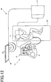
- Fig. 12 is illustrative of the surgical system 90 to which the manipulator 1 according to the embodiment described herein is applied
- Fig. 13 is illustrative in configuration of the surgical system 90 to which the manipulator 1 according to the embodiment described herein is applied.
- the surgical system 90 includes an operating part 40 operated by an operator O, a manipulator 10 that is capable of being inserted through the body of a patient P lying on an operating table BD, that is, a soft organ such as the large intestine or the like and includes a movable part 20 provided at the distal end with a treatment tool 21a shown in Fig. 11 like an endoscope, a control unit 91 for controlling the manipulator 10, and a display unit 92 for displaying an image acquired through an imaging unit 21c of an endoscope built in the manipulator 10 or the like.
- the operating part 40 includes a pair of operating handles attached to an operating base, a footswitch or the like located on the surface of the floor.
- the operating part 40 may have a multi-joint structure.
- the operational angle of the operating part 40 is acquired by an angle acquisition device such as an encoder, and in response to the thus obtained signal, as depicted in Fig. 13 , the control unit 91 actuates the treatment tool 21b or the like located at the distal end of the treatment portion 21a or the like by way of a driver 91a.
- An image acquired through the imaging unit 21c is produced out to an image processor 91b in the control unit 91.
- the image processed by the image processor 91b is produced as a screen display on the display unit 92, and the operator O operates the manipulator 10 while viewing the image appearing on the display unit 92.
- Such surgical system 90 does not only have an advantage of the traction balance adjustment mechanism 1 but is also capable of producing an unerring image display asked for by the operator, resulting in more unerring operation of the manipulator 10 by the operator.
- Such traction balance adjustment mechanism 1 as explained with reference to the embodiment described herein includes the movable part 2 that operates through at least one degree of freedom, the wires 7 connected to the movable part 2, and the traction part 6 adapted to pull one of the wires 7 and push out the other, wherein the length of one wire 7 pulled by the traction part 6 is longer than that length of the other wire 7 pushed out. It is thus possible to put the movable part 2 into unerring operation with no generation of any dynamic surplus in the wires 7.
- the traction part 6 includes the pulleys 61 and 62 that are capable of rotating with respect to a given axis, wherein the pulley 61 includes the helical take-up portions 61 2 , 61 4 , 62 a1 and 62a 2 around which the wire 7 is wound, and which have the smallest-diameter sites 61 2min , 61 4min and 62a min having the shortest distance from the axes 61c and 62c and the largest-diameter sites 61 2max , 61 4max , 62a max1 and 62a max2 having the longest distances from the axes 61c and 62c.
- the simple structure can be used to put the movable part 2 into unerring operation with no generation of any dynamic surplus in the wire 7.
- the wire 7 includes at least one pair of first wire 7a and second wire 7b
- the movable part 2 includes a first connector 2a that makes a connection to one end of the first wire 7a and a second connector 2b that makes a connection to one end of the second wire 7b
- the pulley 61 includes a first take-up portion 61 2 which has a first largest-diameter site 61 2max and around which the first wire 7a is wound and a second take-up portion 61 4 which has a second largest-diameter site 61 4max and around which the second wire 7b is wound
- the smallest-diameter sites 61 2min and 61 4min include a first smallest-diameter site 61 2min adjacent to a first mount 61a to which the other end of the first wire 7a wound around the first take-up portion 61 2 is attached and a second smallest-diameter site 61 4min adjacent to a second mount
- the traction part 6 includes driving gears 63a 1 and 63b 1 that are rotatable with respect to a given axis and first driven gear 63a 2 and second driven gear 63b 2 in mesh with the driving gears 63a 1 and 63b 1 , respectively;
- the wire 7 includes at least one pair of first wire 7a and second wire 7b;
- the movable part 2 includes a first connector 2a that makes a connection to one end of the first wire 7a and a second connector 2b that makes a connection to one end of the second wire 7b, wherein the first driven gear 63a2 includes a first take-up portion 63a 3 around which the first wire 7a is wound, the second driven gear 63b 2 includes a second take-up portion 63b 3 around which the second wire 7b is wound, the first take-up portion 63a 3 includes a first smallest-diameter site 63a min3 to which the other end of the first wire 7a is
- the traction part 6 includes driving gears 64a 1 and 64b 1 that are rotatable with respect to a given axis 64c and first driven member 64a 2 and second driven member 64b 2 in mesh with the driving gears 64a 1 and 64b 1 , respectively;
- the wire 7 includes at least one pair of first wire 7a and second wire 7b;
- the movable part 2 includes a first connector 2a that makes a connection to one end of the first wire 7a and a second connector 2b that makes a connection to one end of the second wire 7b, wherein the first driven member 64a 2 includes a first mount 64a 4 to which the first wire 7a is attached, the second driven member 64b 2 includes a second mount 63b 4 to which the second wire 7b is attached, the driving gears 64a 1 and 64b 1 include a first driving gear 64a 1 provided with a first driving smallest-diameter site 64a min1 and a first driving largest-diameter site 64a
- the traction balance adjustment mechanism 1 includes a coupler 3 that supports the movable part 2 in a rotatable manner, and a gimbal mechanism including a support member 80 for supporting the coupler 3, a first frame member 81 that is rotatably attached to a given first axis with respect to the support member 80 and a second frame member 82 that is rotatably attached to a given second axis with respect to the first frame member 81, the second axis being different from the first axis, wherein the traction part 6 is attached to the first frame member 81.
- the simple structure can be used to put the wire 7 into unerring operation with enhanced operability but with no generation of any dynamic surplus in the wire 7.
- the manipulator 10 includes a driving part 50 that drives a traction part 6, an operating part 40 that puts the driving part 50 into operation to operate the orientation of the movable part 20, and a traction balance adjustment mechanism 1. It is thus possible not only to have an advantage of the traction balance adjustment mechanism 1 but also to rapidly curve the movable part 20 in the direction of traction of the wire 7 so that the distal-end portion 21 can be unerringly directed to the subject of interest.
- the surgical system 90 includes a manipulator 10, a system control unit 91 that controls the manipulator 10, and a display unit 92 that displays an image acquired by the manipulator 10, wherein the manipulator 10 includes an imaging unit 21c, and the system control unit 91 displays an image through the imaging unit 21c on a display unit 92. It is thus possible not only to have an advantage of the traction balance adjustment mechanism 1 but also to provide an unerring image asked for by the operator, making it for the operator to put the manipulator 10 into more unerring operation.
Abstract
Description
- The present invention relates to a traction balance adjustment mechanism capable of adjusting balance in traction of wires through an apparatus which operates a distal-end member by pulling and letting out the wires, a manipulator and a manipulator system.
- So far there has been a manipulator available in which the curving state of a distal-end portion is operated by pulling and letting out a wire. At the time when the wire is driven, there is an elongation of the wire on the pulling side. For this reason, as the wire is pulled and let out at the same stroke, it causes a slack in the wire on the let-out side, resulting possibly in defections such as deviation of the wire out of the pathway.
-
Patent Publication 1 discloses that in order to prevent operating wires from slackening upon operation of a curving portion to make sure a good operational feeling, the center axis of the take-up portion of a pulley to which the base ends of operating wires are fixed is decentered with respect to the rotating center axis of the pulley. - Patent Publication 1:
JP(A) 2008-142199 - With the technology set forth in
Patent Publication 1, the amount of a wire pulled is greater than the amount of a wire let out at a pulley's rotation angle of up to 90°, but at a pulley's rotation angle of greater than 90°, the amount of the wire let out is more than the amount of the wire pulled. At a pulley's rotation angle of greater than 90°, therefore, there may possibly be slack in the wire let out. - Having been made with the problem in mind, an embodiment of the invention has for its object to provide a traction balance adjustment mechanism, a manipulator, and a manipulator system, which can all go into unerring operation with no generation of any dynamic surplus.
- The traction balance adjustment mechanism according to one embodiment of the invention is characterized by including:
- a movable part that operates through at least one degree of freedom,
- power transmission members that are connected to the movable part, and
- a traction part that pulls one of the power transmission members and pushes out the other, wherein the length of the one power transmission member pulled by the traction part is longer than the length of the other power transmission member pushed out.
- In the traction balance adjustment mechanism according to one embodiment of the invention, the amount of change in the length of the one power transmission member pulled by the traction part is constant or incremental.
- In the traction balance adjustment mechanism according to one embodiment of the invention, the amount of change is constantly incremental.
- In the traction balance adjustment mechanism according to one embodiment of the invention, the amount of change is incremental at a constant rate.
- In the traction balance adjustment mechanism according to one embodiment of the invention, the traction part includes a pulley rotatable with respect to a given axis, and
the pulley includes a helical take-up portion for taking up the power transmission members, wherein the take-up portion has a smallest-diameter site having a shortest distance from the axis and a largest-diameter site having a longest distance from the axis. - In the traction balance adjustment mechanism according to one embodiment of the invention, the power transmission members include at least one pair of first and second power transmission members,
the movable part includes a first connector that makes a connection to one end of the first power transmission member and a second connector that makes a connection to one end of the second power transmission member,
the pulley includes a first take-up portion that has a first largest-diameter site and is capable of taking up the first power transmission member and a second take-up portion that has a second largest-diameter site and is capable of taking up the second power transmission member, and
the smallest-diameter site includes a first smallest-diameter site adjacent to a first mount to which the other end of the first power transmission member wound around the first take-up portion is attached and a second smallest-diameter site adjacent to a second mount to which the other end of the second power transmission member wound around the second take-up portion is attached. - In the traction balance adjustment mechanism according to one embodiment of the invention,
the traction part includes a driving gear that is capable of rotating with respect to a given axis, and a first driven gear and a second driven gear in mesh with the driving gear,
the power transmission member includes at least one pair of a first power transmission member and a second power transmission member,
the movable part includes a first connector that makes a connection to one end of the first power transmission member and a second connector that makes a connection to one end of the second power transmission member,
the first driven gear includes a first take-up portion for taking up the first power transmission member,
the second driven gear includes a second take-up portion for taking up the second power transmission member,
the first take-up portion includes a first smallest-diameter site adjacent to a first mount to which the other end of the first power transmission member is attached and a first largest-diameter site positioned at an outermost circumstance thereof, and
the second take-up portion includes a second smallest-diameter site adjacent to a second mount to which the other end of the second power transmission member is attached and a second largest-diameter site positioned at an outermost circumstance thereof. - In the traction balance adjustment mechanism according to one embodiment of the invention, the traction part includes a driving gear that is capable of rotating with respect to a given axis, and a first driven gear and a second driven gear in mesh with the driving gear,
the power transmission member includes at least one pair of a first power transmission member and a second power transmission member,
the movable part includes a first connector that makes a connection to one end of the first power transmission member and a second connector that makes a connection to one end of the second power transmission member,
the first driven member includes a first mount to which the first power transmission member is attached,
the second driven member includes a second mount to which the second power transmission member is attached,
the driving gear includes a first driving gear provided with a first driving smallest-diameter site and a first driving largest-diameter site and a second driving gear provided with a second driving smallest-diameter site and a second driving largest-diameter site,
a tooth tilting rate of the first driven member is compatible with an incremental/ decremental rate of diameter of the first driving gear such that a straight line in an extension direction of the first power transmission member lies always in the same position, and
a tooth tilting rate of the second driven member is compatible with an incremental/ decremental rate of diameter of the second driving gear such that a straight line in an extension direction of the second power transmission member lies always in the same position. - The traction balance adjustment mechanism according to one embodiment of the invention includes:
- a coupler for supporting the movable part in a rotatable manner, and
- a gimbal mechanism including a support member for supporting the coupler, a first frame member that is rotatably attached to a given first axis with respect to the support member, and a second frame member that is rotatably attached to a given second axis with respect to the first support member, the second axis being different from the first axis, wherein the traction part is attached to the first frame member.
- The manipulator according to one embodiment of the invention is characterized by including:
- a driving part for driving the traction part,
- an operating part for actuating the driving part to operate an orientation of the movable part, and
- the traction balance adjustment mechanism.
- The manipulator system according to one embodiment of the invention is characterized by including:
- the manipulator,
- a system control unit for controlling the manipulator, and
- a display unit for displaying an image acquired through the manipulator, wherein the manipulator includes an endoscope, and the system control unit is adapted to display an image acquired through the endoscope on the display unit.
- The traction balance adjustment mechanism, manipulator and manipulator system according to certain embodiments of the invention can all go into unerring operation with no generation of any dynamic surplus.
-
-
Fig. 1 is illustrative in schematic of the traction balance adjustment mechanism according to one embodiment of the invention. -
Fig. 2 is illustrative in schematic of thetraction part 6 according to the first embodiment of the invention. -
Fig. 3 is a view ofFig. 2 as viewed from the opposite side. -
Fig. 4 is illustrative in schematic of one operating state of thetraction part 6 according to the first embodiment. -
Fig. 5 is illustrative in schematic of an operating state of thetraction part 6 according to the first embodiment, which state is different from that ofFig. 4 . -
Fig. 6 is illustrative in schematic of thetraction part 6 according to the second embodiment of the invention. -
Fig. 7 is illustrative in schematic of thetraction part 6 according to the third embodiment of the invention. -
Fig. 8 is illustrative in schematic of thetraction part 6 according to the fourth embodiment of the invention. -
Fig. 9 is illustrative in schematic of thetraction part 6 according to the fifth embodiment of the invention. -
Fig. 10 is illustrative in schematic of themanipulator 10 according to one embodiment of the invention. -
Fig. 11 is an enlarged view of themovable part 20 in themanipulator 10 according to one embodiment of the invention. -
Fig. 12 is illustrative of one example of the manipulator system according to one embodiment of the invention. -
Fig. 13 is a block diagram for one example of the manipulator system according to one embodiment of the invention. - Some embodiments of the invention will now be explained.
-
Fig. 1 is a schematic view of the tractionbalance adjustment mechanism 1 according to one embodiment of the invention. - The traction
balance adjustment mechanism 1 includes amovable part 2, acoupler 3, an operatingpart 4, a drivingpart 5, atraction part 6, andwires 7. - The
movable part 2 is a tubular member that is rotatably mounted with anaxial member 2c extending through themovable part 2 andcoupler 3 as center. Themovable part 2 includes wire mounts 2a and 2b to which one ends of thewires 7 are attached. Thecoupler 3 is a tubular member that couples the operatingpart 4 to themovable part 2 and has thewires 7 inserted inside. - The operating
part 4 includes agrip 41 grasped by an operator, and anoperation instruction portion 42 that is formed at thegrip 41 and includes a joystick or the like for giving an instruction about the operation of themovable part 2. - While the
grip 41 here is formed into a cylindrical shape, it may be configured into any desired easy-to-grasp shape. Theoperation instruction portion 42 is designed such that a protruding rod-form lever is tilted down, as is the case with a joystick using a potentiometer, to bend themovable part 2 in the tilting-down direction. Note here that a pointing device, a touchpad or the like may be used for theoperation instruction portion 42. - The driving
part 5 is built in thegrip 41 of the operatingpart 4. The drivingpart 5 includes an actuator or the like adapted to drive thetraction part 6, to which the other end of thewires 7 is attached, to enable thewires 7 to be pulled and let out. - It is here to be noted that the driving
part 5 is incorporated together with thetraction part 6 in thecoupler 3, and a motor or the like that enables thewires 7 to be wound around or let out from thetraction part 6 may be used for the actuator that forms part of the drivingpart 5 of the first embodiment. -
Fig. 2 is a schematic view of thetraction part 6 according to the first embodiment of the invention, andFig. 3 is a view ofFig. 2 as viewed from the opposite side. - The
traction part 6 according to the first embodiment of the invention may be apulley 61 that is driven by the drivingpart 5 for rotation. Thepulley 61 includes afirst wire mount 61a to which the other end of afirst wire 7a is attached, asecond wire mount 61b to which the other end of asecond wire 7b is attached, and acenter axis 61c that defines the center of rotation. - The
pulley 61 includes, in order from one of the axial direction of thecenter axis 61c to another, afirst surface portion 611, a first take-upportion 612, anintermediate portion 613, a second take-upportion 614, and asecond surface portion 615. Thefirst surface portion 611intermediate portion 613 andsecond surface portion 615 may each be formed of a circular plate. - The first take-up
portion 612 is positioned between thefirst surface potion 611 and theintermediate portion 613 and has a diameter smaller than those of thefirst surface portion 611 andintermediate portion 613. Thefirst wire mount 61a is formed in the vicinity of the first smallest-diameter site 612min where theouter circumference 612a of the first take-upportion 612 has the smallest diameter. - From the first smallest-
diameter site 612min having the smallest diameter to the first largest-diameter site 612max having the largest diameter, the diameter of theouter circumference 612a of the first take-upportion 612 is kept at least constant or incremental or, alternatively not decremental, making sure stable operation of the first take-upportion 612. - Especially from the first smallest-diameter site 612me having the smallest diameter to the first largest-
diameter site 612max having the largest diameter, the diameter of theouter circumference 612a of the first take-upportion 612 is preferably kept incremental, and more preferably incremental at a constant rate, making sure more stable operation of the first take-upportion 612. - The second take-up
portion 614 is positioned between theintermediate portion 613 and thesecond surface portion 615 and has a diameter smaller than those of theintermediate portion 613 andsecond surface portion 615. Thesecond wire mount 61b is formed in the vicinity of the second smallest-diameter site 614min where theouter circumference 614a of the second take-upportion 614 has the smallest diameter. - From the second smallest-
diameter site 614min having the smallest diameter to the second largest-diameter site 614max having the largest diameter, the diameter of theouter circumference 614a of the second take-upportion 614 is kept at least constant or incremental or, alternatively, not decremental, making sure stable operation of the second take-upportion 614. - Especially from the second smallest-
diameter site 614min having the smallest diameter to the second largest-diameter site 614max having the largest diameter, the diameter of theouter circumference 614a of the first take-upportion 614 is preferably incremental, and more preferably incremental at a constant rate, making sure more stable operation of the first take-upportion 614. -
Fig. 4 is a schematic view of the operating state of thetraction part 6 according to the first embodiment of the invention, andFig. 5 is a schematic view of the operating state of thetraction part 6 according to the first embodiment, which state is different from that ofFig. 4 . - As the
pulley 61 is rotated in the take-up direction of thefirst wire 7a from the state ofFig. 2 to the state ofFig. 4 , it causes thefirst wire 7a to be wound on theouter circumference 612a of the first take-upportion 612 and thesecond wire 7b to let out of theouter circumference 614a of the second take-upportion 614. In the process of rotation of thepulley 61 from the state ofFig. 2 to the state ofFig. 4 , the length of thefirst wire 7a taken up gets longer than the length of thesecond wire 7b let out, because the diameter of theouter circumference 612a of the first take-upportion 612 on which thefirst wire 7a is wound is greater than the diameter of theouter circumference 614a of the second take-upportion 614 of which thesecond wire 7b is let out. - Likewise in the process of rotation of the
pulley 61 from the state ofFig. 4 to the state ofFig. 5 , the length of thefirst wire 7a wound up gets longer than the length of thesecond wire 7b let out, because the diameter of theouter circumference 612a of the first take-upportion 612 on which thefirst wire 7a is wound is greater than the diameter of theouter circumference 614a of the second take-upportion 614 of which thesecond wire 7b is let out. - Thus, the
movable part 2 can go into operation without any slack in thesecond wire 7b; the simple structure may be used for unerring operation of themovable part 2 without generation of any dynamic surplus in thewires 7. -
Fig. 6 is a schematic view of thetraction part 6 according to the second embodiment of the invention. - As shown in
Fig. 6 , thetraction part 6 according to the second embodiment includes a spool-like pulley 62 formed of a cylindrical member that is smaller in diameter near its central axis portion than at both its end portions. Thepulley 62 is driven by the drivingpart 5 for rotation with thecenter axis 62c as center. Thepulley 62 is provided on its outer circumference with a take-up portion 62a formed of a spiral groove. - From the smallest-diameter site 62amin positioned at the center of the axial direction and having the smallest diameter to the largest-diameter sites 62amax positioned at both ends and having the largest diameter, the diameter of the take-up portion 62a is kept at least constant or incremental or, alternatively, not decremental. Especially from the smallest-diameter site 62amin having the smallest diameter to the first largest-diameter site 62amax1 having the largest diameter on the
first wire 7a side and the second largest-diameter site 62amax2 having the largest diameter on thesecond wire 7b side, the diameter of the take-up portion 62a is preferably kept incremental, and more preferably incremental at a constant rate. - The take-up portion 62a has the
wire 7 wound around. As shown inFig. 1 , thewire 7 is attached at the end to the wire mounts 2a and 2b of the movable part. It is then preferable that anintermediate point 7c of thewire 7 is set in a position of the smallest-diameter site 62amin of thepulley 62 such that one half is wound as afirst wire portion 7a and the other as asecond wire portion 7b. - It is here to be noted that the
wire 7 is preferably wound around the take-up portion 62a such that it does not slip thereon. As an example, there may be a guide provided at a given site so as to increase frictional force between thewire 7 and the take-up portion 62a. - The
wire 7 may also be divided into two: afirst wire 7a and asecond wire 7b. With thewire 7 divided into two, it is not required that the ends of two wire portions are attached to the position of the smallest-diameter site 62amin of thepulley 62. For instance, thefirst wire 7a may be attached to the first wire mount (not shown) set in any desired position of the first take-upportion 62a1 formed from the smallest-diameter site 62amin to the first largest-diameter site 62amax1, and thesecond wire 7b may be attached to the second wire mount (not shown) set in any desired position of the second take-up portion 62a2 formed from the smallest-diameter site 62amin to the second largest-diameter site 62amax2. - The operation of the
traction part 6 according to the second embodiment of the invention is now explained. - As the
pulley 62 is rotated in the take-up direction of thefirst wire 7a, it causes thefirst wire 7a to be wound on the first take-upportion 62a1 and thesecond wire 7b to be let out of the second take-upportion 62a2. The length of thefirst wire 7a wound up grows longer than the length of thesecond wire 7b let out, because the diameter of the first take-upportion 62a1 on which thefirst wire 7a is wound grows large while the diameter of the second take-up portion 62a2 of which thesecond wire 7b is let out becomes short. - Thus, the
movable part 2 shown inFig. 1 can go into operation without any slack in thesecond wire 7b let out; the simple structure may be used for unerring operation of themovable part 2 without generation of any dynamic surplus in thewire 7. -
Fig. 7 is a schematic view of thetraction part 6 according to the third embodiment of the invention. - A
deformed gear 63 having varying diameters around its outer circumference is used for thetraction part 6 according to the third embodiment, as can be seen fromFig. 7 . The first driving gear 63a1 and the second driving gear 63b1 are driven by the drivingpart 5 for rotation with acommon axis 63c as center. - The diameter of the first driving gear 63a1 is kept at least constant or incremental or, alternatively, not decremental from the smallest-diameter site 63amin1 of the first driving gear having the smallest diameter to the largest-diameter site 63amax1 of the first driving gear having the largest diameter. Especially from the smallest-diameter site 63amin1 of the first driving gear having the smallest diameter to the largest-diameter site 63amax1 of the first driving gear having the largest diameter, the diameter of the first driving gear 63a1 is preferably gradually incremental, and more preferably incremental at a constant rate.
- The diameter of the second driving gear 63b1 is kept at least constant or incremental or, alternatively, not decremental from the smallest-diameter site 63bmin1 of the second driving gear having the smallest diameter to the largest-diameter site 63bmax1 of the second driving gear having the largest diameter. Especially from the smallest-diameter site 63bmin1 of the second driving gear having the smallest diameter to the largest-diameter site 63bmax1 of the second driving gear having the largest diameter, the diameter of the second driving gear 63b1 is preferably gradually incremental, and more preferably incremental at a constant rate.
- A first driven gear 63a2 is in mesh with the first driving gear 63a1, and as the first driving gear 63a1 is driven, the first driven gear 63a2 rotates about a first driven center axis 63ac parallel with the
driving center axis 63c. The incremental rate of the diameter of the first driven gear 63a2 is determined corresponding to the diameter of the first driving gear 63a1. As an example, it is preferable that the first driven gear 63a2 engages and rotates with the first driving gear 63a1 while the distance from thecenter axis 63c of the first driving gear 63a1 to the first driven center axis 63ac of the first driven gear 63a2 remains constant. - The teeth of the first driven gear 63a2 are provided with a first take-up portion 63a3 including a groove. From the smallest-diameter site 63amin3 of the first take-up portion having the smallest diameter to the largest-diameter site 63amax3 of the first take-up portion having the largest diameter, the diameter of the first take-up portion 63a3 is kept at least constant or incremental or, alternatively, not decremental. Especially from the smallest-diameter site 63amin3 of the first take-up portion having the smallest diameter to the largest-diameter site 63amax3 of the first take-up portion having the largest diameter, the diameter of the first take-up portion 63a3 is preferably gradually incremental, and more preferably incremental at a constant rate.
- The first driven gear 63a2 includes a first wire mount 63a4 to which a
first wire 7a attached at one end to themovable part 2 shown inFig. 1 is attached at the other end. Thefirst wire 7a is wound around the first take-up portion 63a3. - A second driven gear 63b2 is in mesh with the second driving gear 63b1, and as the second driving gear 63b1 is driven, the second driven gear 63b2 rotates about a second driven center axis 63bc parallel with the
driving center axis 63c. The incremental rate of diameter of the second driven gear 63b2 is determined corresponding to the diameter of the second driving gear 63b1. As an example, it is preferable that the second driven gear 63b2 engages and rotates with the second driving gear 63b1 while the distance from thecenter axis 63c of the second driving gear 63b1 to the second driven center axis 63bc of the second driven gear 63b2 remains constant. - The teeth of the second driven gear 63b2 are provided with a second take-up portion 63b3 including a groove. From the smallest-diameter site 63bmin3 of the second take-up portion having the smallest diameter to the largest-diameter site 63bmax3 of the second take-up portion having the largest diameter, the diameter of the second take-up portion 63b3 is kept at least constant or incremental or, alternatively, not decremental. Especially from the smallest-diameter site 63bmin3 of the second take-up portion having the smallest diameter to the largest-diameter site 63bmax3 of the second take-up portion having the largest diameter, the diameter of the second take-up portion 63b3 is preferably gradually incremental, and more preferably incremental at a constant rate.
- The second driven gear 63b2 includes a second wire mount 63b4 to which a
second wire 7b attached at one end to themovable part 2 shown inFig. 1 is attached at the other end. Thesecond wire 7b is wound around the second take-up portion 63b3. - The operation of the
traction part 6 according to the third embodiment of the invention is now explained. - As the first driving gear 63a1 is rotated in the take-up direction of the
first wire 7a and the second driving gear 63b1 is rotated in the direction in which thesecond wire 7b is let out, it causes thefirst wire 7a to be wound on the first take-up portion 63a3 of the first driven gear 63a2 and thesecond wire 7b to be let out of the second take-up portion 63b3 of the second driven gear 63b2. The length of thefirst wire 7a wound up grows longer than the length of thesecond wire 7b let out, because the diameter of the first take-up portion 63a3 on which thefirst wire 7a is would grows large while the diameter of the second take-up portion 63b3 from which thesecond wire 7b is let out becomes small. - Thus, the
movable part 2 shown inFig. 1 can go into operation without any slack in thesecond wire 7b let out; the simple structure may be used for unerring operation of themovable part 2 without generation of any dynamic surplus in thewire 7. -
Fig. 8 is a schematic view of thetraction part 6 according to the fourth embodiment of the invention. - As can be seen from
Fig. 8 , thetraction part 6 according to the fourth embodiment is defined by a deformed rack-and-pinion mechanism including a deformed pinion member having varying outer circumference diameters and a rack member having a tilting tooth potion. A first 64a1 and a second driving gear 64b1, forming the deformed pinion member, are driven by the drivingpart 5 shown inFig. 1 for rotation about acommon center axis 64c. A first driven member 64a2 and a second driven member 64b2, forming the rack member having a tilting tooth portion, are in mesh with the first driving gear 64a1 and the second driving gear 64b1, respectively. - From the smallest-diameter portion 64amin1 of the first driving gear having the smallest diameter to the largest-diameter portion 64amax1 of the first driving gear having the largest diameter, the diameter of the first driving gear 64a1 is kept at least constant or incremental or, alternatively, not decremental. Especially from the smallest-diameter portion 64amin1 of the first driving gear having the smallest diameter to the largest-diameter portion 64amax1 of the first driving gear having the largest diameter, the diameter of the first driving gear 64a1 is preferably gradually incremental, and more preferably incremental at a constant rate.
- From the smallest-diameter portion 64bmin1 of the second driving gear having the smallest diameter to the largest-diameter portion 64bmax1 of the second driving gear having the largest diameter, the diameter of the second driving gear 64b1 is kept at least constant or incremental or, alternatively, not decremental. Especially from the smallest-diameter portion 64bmin1 of the second driving gear having the smallest diameter to the largest-diameter portion 64bmax1 of the second driving gear having the largest diameter, the diameter of the second driving gear 64b1 is preferably gradually incremental, and more preferably incremental at a constant rate.
- The first driven member 64a2 includes a first wire mount 64a4 to which the
first wire 7a attached at one end to the movable part 2 (shown inFig. 1 ) is attached at the other end. The first driven member 64a2 meshes with the first driving gear 64a1 and moves linearly in a plane orthogonal to thedriving center axis 64c as the first driving gear 64a1 is driven. As an example, it is preferable that the tooth tilting rate of the first driven member 64a2 is compatible with the incremental/ decremental rate of diameter of the first driving gear 63a1 such that a straight line 7ac in the extension direction of thefirst wire 7a lies always in the same position. For this reason, there may be a guide member (not shown) used so as to move the first driven member 64a2 on the straight line 7ac in the extension direction of thefirst wire 7a. - The second driven member 64b2 includes a second wire mount 64b4 to which the
second wire 7b attached at one end to the movable part 2 (shown inFig. 1 ) is attached at the other end. The second driven member 64b2 meshes with the second driving gear 64b1 and moves linearly in a plane orthogonal to thedriving center axis 64c as the second driving gear 64b1 is driven. As an example, it is preferable that the tooth tilting rate of the second driven member 64b2 is compatible with the incremental/decremental rate of diameter of the second driving gear 63b1 such that a straight line 7bc in the extension direction of thesecond wire 7b lies always in the same position. For this reason, there may be a guide member (not shown) used so as to move the second driven member 64b2 on the straight line 7bc in the extension direction of thesecond wire 7b. - The operation of the
traction part 6 according to the fourth embodiment of the invention is now explained. - As the first driving gear 64a1 and the second driving gear 64b1 are rotated in the direction in which the
first wire 7a is pulled toward the first driven member 64a2 side, it causes the second driven member 64b2 to be pulled by thesecond wire 7b. The length of thefirst wire 7a pulled is longer than the length of thesecond wire 7b let out, because the diameter of the first driving gear 64a1 that pulls thefirst wire 7a gets small as it rotates and the diameter of the second take-up portion 63b3 from which thesecond wire 7b is let out gets short. - Thus, the
movable part 2 shown inFig. 1 can go into operation without any slack in thesecond wire 7b let out; the simple structure may be used for unerring actuation of themovable part 2 without generation of any dynamic surplus in thewire 7. -
Fig. 9 is a schematic view of thetraction part 6 according to the fifth embodiment of the invention. - As can be seen from
Fig. 9 , thetraction part 6 according to the fifth embodiment has an arrangement wherein onepulley 61 according to the first embodiment shown inFig. 2 is divided to two portions, each corresponding to onewire 7, and a gimbal mechanism is used for operation of the movable part 2 (shown inFig. 1 ) through two degrees of freedom. - According to the fifth embodiment, the
traction part 6 includes afirst pulley 65a, asecond pulley 65b, athird pulley 66a, and afourth pulley 66b. Thefirst pulley 65a and thesecond pulley 65b are located in opposite positions. As afirst wire 71a wound around thefirst pulley 65a and asecond wire 71b wound around thesecond pulley 65b are pushed/pulled, it causes themovable part 2 shown inFig. 1 to move in the opposite directions. - It is here to be noted that the
first pulley 65a and thesecond pulley 65b and thethird pulley 66a and thefourth pulley 66b have a similar structure; only the structure of thefirst pulley 65a is now explained with no reference to the rest. - In order from one to another of the axial direction of the center axis 65ac, the
first pulley 65a includes afirst surface portion 65a1, a first take-upportion 65a2, and asecond surface portion 65a3. - The first take-up portion 652 is positioned between the first surface portion 651 and the
second surface portion 65a3 and has a diameter smaller than those of the first surface portion 651 and thesecond surface portion 65a3, and the first wire take-upportion 65a21 is formed near the first smallest-diameter site 65a2min of the outer circumference 652a of the first take-up portion 652. - From the first smallest-diameter site 652min having the smallest diameter to the largest diameter-site 652max having the largest diameter, the diameter of the outer circumference 652a of the first take-up portion 652 is kept at least constant or incremental or, alternatively, not decremental. Especially from the first smallest-diameter site 652min having the smallest diameter to the largest diameter-site 652max having the largest diameter, the diameter of the outer circumference 652a of the first take-up portion 652 is preferably gradually incremental, and more preferably incremental at a constant rate.
- According to the fifth embodiment, the
traction part 6 is attached to agimbal mechanism 8. Thegimbal mechanism 8 includes asupport member 80, afirst frame member 81 rotatably attached to a given axis with respect to thesupport member 80, and asecond frame member 82 rotatably attached to a given axis with respect to thefirst frame member 81. - The
first frame member 81 is supported on a given axis with respect to thesupport member 80 for swinging movement, and supports thetraction member 6 for rotation as well. In the fifth embodiment, thefirst pulley 65a to thefourth pulley 66b are attached to thefirst frame member 81 for each 90°. Note here that thefirst pulley 65a to thefourth pulley 66b are each driven by a driving part (not shown). - The
second frame member 82 is positioned inside thefirst frame member 81, and supported to an axis orthogonal to the axis by which thefirst frame member 81 is supported on thesupport member 80 for swinging movement. Thesecond frame member 82 is provided with at least one of thecoupler 3 and operatingpart 4. Accordingly, thecoupler 3 and operatingpart 4 are capable of going into operation through 2 degrees of freedom with respect to thesupport member 80. - The
wires 7 wound around thefirst pulley 65a to thefourth pulley 66b are guided to themovable part 2 through thecoupler 3 by way of a pulley or guide and so on for changing direction. - Referring here to the traction
balance adjustment mechanism 1 according to the fifth embodiment, as thefirst pulley 65a is rotated in a direction of taking up thefirst wire 71a, it causes thefirst wire 71a to be wound around theouter circumference 65a2a of the first take-upportion 65a2 and thesecond wire 71b to be let out of thesecond pulley 65b. In this case, the length of thefirst wire 71a wound gets longer than the length of thesecond wire 7b let out, because the diameter of theouter circumference 65a2a of the first take-upportion 65a2 around which thefirst wire 71a is wound grows greater than the diameter of the outer circumference of the second take-up portion (not shown) of which thesecond wire 71b is let out. - It is thus possible to put the
movable part 2 in operation with no slack in thesecond wire 71b let out; the simple structure can be used for improved and unerring operation of themovable part 2 with no generation of dynamic surplus in thewire 7. - It is here to be appreciated that the
first pulley 65a,second pulley 65b,third pulley 66a andfourth pulley 66b are similar in structure; so therespective wires 7 may be put into operation much in the same manner too. - The
manipulator 10 according to the embodiment described herein is now explained. -
Fig. 10 is a schematic view of themanipulator 10 according to the embodiment described herein. - The
manipulator 10 according to the embodiment described herein includes amovable part 20, acoupler 30, and an operatingpart 40. Themanipulator 10 includes themovable part 20 on the distal-end side and the operatingpart 40 on the proximal-end side. Inserted through the body cavity, themovable part 20 includes, in order from the distal-end side, a distal-end portion 21 and a curvingportion 22. Coupling themovable part 20 to the operatingpart 40, thecoupler 30 has a wire, etc. built inside. The operatingpart 40 operates movement or the like of themovable part 20. -
Fig. 11 is an enlarged view of themovable part 20 in themanipulator 10 according to the embodiment described herein. - As an example, the
manipulator 10 according to the embodiment described herein makes up an endoscope. The distal-end portion 21 includes ancolumnar treatment portion 21a mounted on the distal end of themanipulator 10, atreatment tool 21b built in thetreatment portion 21a, and animaging portion 21c. Note here that thetreatment tool 21b may be forceps, a electric scalpel, etc. for applying treatments to the subject of interest. Theimaging portion 21c is used for imaging the subject of interest. There may be a lighting portion (not shown) for lighting the subject of interest. - The curving
portion 22 includes substantially columnar articulatingpieces 22a and ajoint portion 22b adapted to couple adjoining articulatingpieces 22a in a rotatable manner within a given angle range. As depicted inFig. 11 , a set of adjoining articulatingpieces 22a andjoint portion 22b is preferably rotated 90° and located about the axis of the curvingportion 22 extended in a straight line, i.e., the center axis C of thecoupler 30. - The distal-
end portion 21 is attached to the most distal articulatingpiece 22a of the curvingportion 22 by way of thejoint portion 22b, and the articulatingpiece 22a positioned on the most proximal end side of the curvingportion 22 is coupled to thecoupler 30 by way of thejoint portion 22b. - It is here to be noted that the
movable part 20 is not limited to the structure; so it may be modified in various fashions. - As the operating
part 40 in themanipulator 10 according to the embodiment described herein is operated by an operator, it cause one of thewires 7 wound around thetraction part 6 shown inFig. 1 to be hauled, and themovable part 20 is curved in a direction of thewire 7 being hauled so that the distal-end portion 21 can be pointed to the subject of interest. - The
surgical system 90 according to the embodiment described herein is now explained as an example of the manipulator system to which themanipulator 10 according to the embodiment described herein is applied. -
Fig. 12 is illustrative of thesurgical system 90 to which themanipulator 1 according to the embodiment described herein is applied, andFig. 13 is illustrative in configuration of thesurgical system 90 to which themanipulator 1 according to the embodiment described herein is applied. - Applied to the
surgical system 90 according to the embodiment described herein is themanipulator 10 shown inFig. 12 . Thesurgical system 90 includes an operatingpart 40 operated by an operator O, amanipulator 10 that is capable of being inserted through the body of a patient P lying on an operating table BD, that is, a soft organ such as the large intestine or the like and includes amovable part 20 provided at the distal end with atreatment tool 21a shown inFig. 11 like an endoscope, acontrol unit 91 for controlling themanipulator 10, and adisplay unit 92 for displaying an image acquired through animaging unit 21c of an endoscope built in themanipulator 10 or the like. - As depicted in
Fig. 12 , the operatingpart 40 includes a pair of operating handles attached to an operating base, a footswitch or the like located on the surface of the floor. The operatingpart 40 may have a multi-joint structure. The operational angle of the operatingpart 40 is acquired by an angle acquisition device such as an encoder, and in response to the thus obtained signal, as depicted inFig. 13 , thecontrol unit 91 actuates thetreatment tool 21b or the like located at the distal end of thetreatment portion 21a or the like by way of adriver 91a. - An image acquired through the
imaging unit 21c is produced out to animage processor 91b in thecontrol unit 91. The image processed by theimage processor 91b is produced as a screen display on thedisplay unit 92, and the operator O operates themanipulator 10 while viewing the image appearing on thedisplay unit 92. - Such
surgical system 90 does not only have an advantage of the tractionbalance adjustment mechanism 1 but is also capable of producing an unerring image display asked for by the operator, resulting in more unerring operation of themanipulator 10 by the operator. - Such traction
balance adjustment mechanism 1 as explained with reference to the embodiment described herein includes themovable part 2 that operates through at least one degree of freedom, thewires 7 connected to themovable part 2, and thetraction part 6 adapted to pull one of thewires 7 and push out the other, wherein the length of onewire 7 pulled by thetraction part 6 is longer than that length of theother wire 7 pushed out. It is thus possible to put themovable part 2 into unerring operation with no generation of any dynamic surplus in thewires 7. - With the traction
balance adjustment mechanism 1 according to the embodiment described herein, it is possible to put themovable part 2 into stable operation, because the amount of change in the length of onewire 7 pulled by thetraction part 6 is kept constant or incremental. - With the traction
balance adjustment mechanism 1 according to the embodiment described herein, it is possible to put themovable part 2 into more stable operation, because the amount of change is constantly incremental. - With the traction
balance adjustment mechanism 1 according to the embodiment described herein, it is possible to put themovable part 2 into more stable operation, because the amount of change is incremental at a constant rate. - In the traction
balance adjustment mechanism 1 according to one embodiment of the invention, thetraction part 6 includes thepulleys pulley 61 includes the helical take-upportions wire 7 is wound, and which have the smallest-diameter sites axes diameter sites axes movable part 2 into unerring operation with no generation of any dynamic surplus in thewire 7. - In the traction
balance adjustment mechanism 1 according to the embodiment described herein, thewire 7 includes at least one pair offirst wire 7a andsecond wire 7b, themovable part 2 includes afirst connector 2a that makes a connection to one end of thefirst wire 7a and asecond connector 2b that makes a connection to one end of thesecond wire 7b, thepulley 61 includes a first take-upportion 612 which has a first largest-diameter site 612max and around which thefirst wire 7a is wound and a second take-upportion 614 which has a second largest-diameter site 614max and around which thesecond wire 7b is wound, and the smallest-diameter sites diameter site 612min adjacent to afirst mount 61a to which the other end of thefirst wire 7a wound around the first take-upportion 612 is attached and a second smallest-diameter site 614min adjacent to asecond mount 61b to which the other end of thesecond wire 7b around the second take-upportion 614 is attached. Thus, the simple structure can be used for rapid removal of any dynamic surplus in thewire 7 thereby making sure unerring operation of thewire 7. - In the traction
balance adjustment mechanism 1 according to the embodiment described herein, thetraction part 6 includes driving gears 63a1 and 63b1 that are rotatable with respect to a given axis and first driven gear 63a2 and second driven gear 63b2 in mesh with the driving gears 63a1 and 63b1, respectively; thewire 7 includes at least one pair offirst wire 7a andsecond wire 7b; and themovable part 2 includes afirst connector 2a that makes a connection to one end of thefirst wire 7a and asecond connector 2b that makes a connection to one end of thesecond wire 7b, wherein the first driven gear 63a2 includes a first take-up portion 63a3 around which thefirst wire 7a is wound, the second driven gear 63b2 includes a second take-up portion 63b3 around which thesecond wire 7b is wound, the first take-up portion 63a3 includes a first smallest-diameter site 63amin3 to which the other end of thefirst wire 7a is attached and a first largest-diameter site 63amax3 positioned on the outermost circumference, and the second take-up portion 63b3 includes a second smallest-diameter site 63bmin3 to which the other end of thesecond wire 7b is attached and a second largest-diameter site 63bmax3 positioned on the outermost circumference. Thus, the simple structure can be used to put thewire 7 into unerring operation with no generation of any dynamic surplus in thewire 7. - In the traction balance adjustment mechanism 1 according to the embodiment described herein, the traction part 6 includes driving gears 64a1 and 64b1 that are rotatable with respect to a given axis 64c and first driven member 64a2 and second driven member 64b2 in mesh with the driving gears 64a1 and 64b1, respectively; the wire 7 includes at least one pair of first wire 7a and second wire 7b; and the movable part 2 includes a first connector 2a that makes a connection to one end of the first wire 7a and a second connector 2b that makes a connection to one end of the second wire 7b, wherein the first driven member 64a2 includes a first mount 64a4 to which the first wire 7a is attached, the second driven member 64b2 includes a second mount 63b4 to which the second wire 7b is attached, the driving gears 64a1 and 64b1 include a first driving gear 64a1 provided with a first driving smallest-diameter site 64amin1 and a first driving largest-diameter site 64amax1 and a second driving gear 64b1 provided with a second driving smallest-diameter site 64bmin1 and a second driving largest-diameter site 64bmax1, the tooth tilting rate of the first driven member 64a2 is compatible with the incremental/decremental rate of diameter of the first driving gear 64a1 such that the straight line in the direction of extension of the first wire 7a lies always in the same position, and the tooth tilting rate of the second driven member 64b2 is compatible with the incremental/decremental rate of diameter of the second driving gear 64b1 such that the straight line in the direction of extension of the second wire 7b lies always in the same position. Thus, the simple structure can be used to put the
wire 7 into unerring operation with no generation of any dynamic surplus in thewire 7. - The traction
balance adjustment mechanism 1 according to the embodiment described herein includes acoupler 3 that supports themovable part 2 in a rotatable manner, and a gimbal mechanism including asupport member 80 for supporting thecoupler 3, afirst frame member 81 that is rotatably attached to a given first axis with respect to thesupport member 80 and asecond frame member 82 that is rotatably attached to a given second axis with respect to thefirst frame member 81, the second axis being different from the first axis, wherein thetraction part 6 is attached to thefirst frame member 81. Thus, the simple structure can be used to put thewire 7 into unerring operation with enhanced operability but with no generation of any dynamic surplus in thewire 7. - The
manipulator 10 according to the embodiment described herein includes a drivingpart 50 that drives atraction part 6, an operatingpart 40 that puts the drivingpart 50 into operation to operate the orientation of themovable part 20, and a tractionbalance adjustment mechanism 1. It is thus possible not only to have an advantage of the tractionbalance adjustment mechanism 1 but also to rapidly curve themovable part 20 in the direction of traction of thewire 7 so that the distal-end portion 21 can be unerringly directed to the subject of interest. - The
surgical system 90 according to the embodiment described herein includes amanipulator 10, asystem control unit 91 that controls themanipulator 10, and adisplay unit 92 that displays an image acquired by themanipulator 10, wherein themanipulator 10 includes animaging unit 21c, and thesystem control unit 91 displays an image through theimaging unit 21c on adisplay unit 92. It is thus possible not only to have an advantage of the tractionbalance adjustment mechanism 1 but also to provide an unerring image asked for by the operator, making it for the operator to put themanipulator 10 into more unerring operation. - It is here to be appreciated that the invention is in no sense limited to such embodiments as described above. While the explanation of some embodiments embraces numerous specific details for illustration, it would be obvious to those skilled in the art that diverse variations or modifications made thereto are included within the scope of the invention. In other words, illustrative embodiments of the invention are described without excluding generality from the claimed inventions and imposing any limitation thereon.
-
- 1:
- Traction balance adjustment mechanism
- 2:
- Movable part
- 3:
- Coupler
- 4:
- Operating part
- 5:
- Driving part
- 6:
- Traction part
- 61, 62:
- Pulley
- 63:
- Deformed gear
- 64:
- Guide for interconnecting pulleys
- 7:
- Wire (power transmission member)
- 8:
- Surplus absorber
- 10:
- Manipulator
- 20:
- Movable part
- 21:
- Distal-end portion
- 22:
- Curving portion
- 30:
- Coupler
- 40:
- Operating part
- 90:
- Surgical system (manipulator system)
- 91:
- Control unit
- 92:
- Display unit
Claims (11)
- A traction balance adjustment mechanism, characterized by comprising:a movable part that operates through at least one degree of freedom;power transmission members that are connected to the movable part; anda traction part that pulls one of the power transmission members and pushes out the other;wherein a length of the one power transmission member pulled by the traction part is longer than a length of the other power transmission member pushed out.
- A traction balance adjustment mechanism according to claim 1, wherein an amount of change in the length of the one power transmission member pulled by the traction part is constant or incremental.
- A traction balance adjustment mechanism according to claim 2, wherein the amount of change is constantly incremental.
- A traction balance adjustment mechanism according to claim 3, wherein the amount of change is incremental at a constant rate.
- A traction balance adjustment mechanism according to any one of claims 1 to 4, wherein the traction part comprises a pulley rotatable with respect to a given axis, and
the pulley includes a helical take-up portion for winding up the power transmission members, wherein the take-up portion has a smallest-diameter site having a shortest distance from the axis and a largest-diameter site having a longest distance from the axis. - A traction balance adjustment mechanism according to claim 5, wherein the power transmission members include at least one pair of first and second power transmission members,
the movable part includes a first connector that makes a connection to one end of the first power transmission member and a second connector that makes a connection to one end of the second power transmission member,
the pulley includes a first take-up portion that has a first largest-diameter site and is capable of winding up the first power transmission member and a second take-up portion that has a second largest-diameter site and is capable of winding up the second power transmission member, and
the smallest-diameter site includes a first smallest-diameter site adjacent to a first mount to which the other end of the first power transmission member wound around the first take-up portion is attached and a second smallest-diameter site adjacent to a second mount to which the other end of the second power transmission member wound around the second take-up portion is attached. - A traction balance adjustment mechanism according to any one of claims 1 to 4, wherein:the traction part includes a driving gear that is capable of rotating with respect to a given axis, and a first driven gear and a second driven gear in mesh with the driving gear,the power transmission members include at least one pair of a first power transmission member and a second power transmission member,the movable part includes a first connector that makes a connection to one end of the first power transmission member and a second connector that makes a connection to one end of the second power transmission member,the first driven gear includes a first take-up portion for winding up the first power transmission member,the second driven gear includes a second take-up portion for winding up the second power transmission member,the first take-up portion includes a first smallest-diameter site adjacent to a first mount to which the other end of the first power transmission member is attached and a first largest-diameter site positioned at an outermost circumstance thereof, andthe second take-up portion includes a second smallest-diameter site adjacent to a second mount to which the other end of the second power transmission member is attached and a second largest-diameter site positioned at an outermost circumstance thereof.
- A traction balance adjustment mechanism according to any one of claims 1 to 4, wherein:the traction part includes a driving gear that is capable of rotating with respect to a given axis, and a first driven gear and a second driven gear in mesh with the driving gear,the power transmission members include at least one pair of a first power transmission member and a second power transmission member,the movable part includes a first connector that makes a connection to one end of the first power transmission member and a second connector that makes a connection to one end of the second power transmission member,the first driven member includes a first mount to which the first power transmission member is attached,the second driven member includes a second mount to which the second power transmission member is attached,the driving gear comprises a first driving gear provided with a first driving smallest-diameter site and a first driving largest-diameter site and a second driving gear provided with a second driving smallest-diameter site and a second driving largest-diameter site,a tooth tilting rate of the first driven member is compatible with an incremental/ decremental rate of diameter of the first driving gear such that a straight line in an extension direction of the first power transmission member lies always in the same position, anda tooth tilting rate of the second driven member is compatible with an incremental/ decremental rate of diameter of the second driving gear such that a straight line in an extension direction of the second power transmission member lies always in the same position.
- A traction balance adjustment mechanism according to any one of claims 1 to 8, which comprises:a coupler for supporting the movable part in a rotatable manner;a gimbal mechanism including a support member for supporting the coupler;a first frame member that is rotatably attached to a given first axis with respect to the support member; anda second frame member that is rotatably attached to a given second axis with respect to the first support member, the second axis being different from the first axis;wherein the traction part is attached to the first frame member.
- A manipulator, characterized by comprising:a driving part for driving the traction part;an operating part for operating the driving part to operate an orientation of the movable part; anda traction balance adjustment mechanism according to any one of claims 1 to 9.
- A manipulator system, characterized by comprising:a manipulator according to claim 10;a system control unit for controlling the manipulator; anda display unit for displaying an image acquired through the manipulator;wherein the manipulator includes an endoscope, and the system control unit is adapted to display an image acquired through the endoscope on the display unit.
Applications Claiming Priority (2)
| Application Number | Priority Date | Filing Date | Title |
|---|---|---|---|
| JP2014021991A JP6210900B2 (en) | 2014-02-07 | 2014-02-07 | Traction balance adjustment mechanism, manipulator and manipulator system |
| PCT/JP2015/051781 WO2015118961A1 (en) | 2014-02-07 | 2015-01-23 | Traction balance adjustment mechanism, manipulator, and manipulator system |
Publications (3)
| Publication Number | Publication Date |
|---|---|
| EP3103374A1 true EP3103374A1 (en) | 2016-12-14 |
| EP3103374A4 EP3103374A4 (en) | 2017-11-01 |
| EP3103374B1 EP3103374B1 (en) | 2019-03-20 |
Family
ID=53777768
Family Applications (1)
| Application Number | Title | Priority Date | Filing Date |
|---|---|---|---|
| EP15746278.9A Active EP3103374B1 (en) | 2014-02-07 | 2015-01-23 | Traction balance adjustment mechanism, manipulator, and manipulator system |
Country Status (5)
| Country | Link |
|---|---|
| US (1) | US10238271B2 (en) |
| EP (1) | EP3103374B1 (en) |
| JP (1) | JP6210900B2 (en) |
| CN (1) | CN105960191B (en) |
| WO (1) | WO2015118961A1 (en) |
Cited By (12)
| Publication number | Priority date | Publication date | Assignee | Title |
|---|---|---|---|---|
| WO2020076417A3 (en) * | 2018-08-17 | 2020-07-16 | Cook Medical Technologies Llc | Endoscope with control for tip deflection |
| WO2021163468A1 (en) * | 2020-02-13 | 2021-08-19 | Intuitive Surgical Operations, Inc. | Devices and methods for coupling a cable to a medical device |
| US11207145B2 (en) | 2016-07-14 | 2021-12-28 | Intuitive Surgical Operations, Inc. | Multi-cable medical instrument |
| US11248686B2 (en) | 2013-08-15 | 2022-02-15 | Intuitive Surgical Operations, Inc. | Lever actuated gimbal plate |
| DE102020121365A1 (en) | 2020-08-13 | 2022-02-17 | Ambu A/S | Endoscope based on the capstan principle |
| US11439376B2 (en) | 2018-03-07 | 2022-09-13 | Intuitive Surgical Operations, Inc. | Low-friction, small profile medical tools having easy-to-assemble components |
| US11452572B2 (en) | 2017-12-14 | 2022-09-27 | Intuitive Surgical Operations, Inc. | Medical tools having tension bands |
| US11478317B2 (en) | 2017-02-24 | 2022-10-25 | Intuitive Surgical Operations, Inc. | Splayed cable guide for a medical instrument |
| US11497567B2 (en) | 2018-02-08 | 2022-11-15 | Intuitive Surgical Operations, Inc. | Jointed control platform |
| US11744656B2 (en) | 2016-07-14 | 2023-09-05 | Intuitive Surgical Operations, Inc. | Geared grip actuation for medical instruments |
| US11864851B2 (en) | 2016-07-14 | 2024-01-09 | Intuitive Surgical Operations, Inc. | Geared roll drive for medical instrument |
| US11969889B2 (en) | 2023-02-24 | 2024-04-30 | Intuitive Surgical Operations, Inc. | Lever actuated gimbal plate |
Families Citing this family (10)
| Publication number | Priority date | Publication date | Assignee | Title |
|---|---|---|---|---|
| JP6329041B2 (en) * | 2014-09-17 | 2018-05-23 | Hoya株式会社 | Endoscope bending operation mechanism |
| US11534579B2 (en) * | 2015-01-02 | 2022-12-27 | 510 Kardiac Devices, Inc. | Steerable introducer sheath assembly |
| JP6710066B2 (en) * | 2016-03-07 | 2020-06-17 | 株式会社カネカ | Catheter handle and catheter having the same |
| US10799675B2 (en) * | 2016-03-21 | 2020-10-13 | Edwards Lifesciences Corporation | Cam controlled multi-direction steerable handles |
| US11104011B2 (en) * | 2016-11-10 | 2021-08-31 | Robert Chisena | Mechanical robot arm assembly |
| CN106491190B (en) * | 2016-12-04 | 2019-09-24 | 李长慧 | Facilitate the ovarian neoplasm puncture outfit for adjusting angle |
| US11104008B2 (en) * | 2019-03-27 | 2021-08-31 | Mitsubishi Electric Research Laboratories, Inc. | Dexterous gripper for robotic end-effector applications |
| US20210338050A1 (en) | 2020-04-30 | 2021-11-04 | Ambu A/S | Endoscope control system |
| US11478140B1 (en) * | 2020-09-15 | 2022-10-25 | Raytrx, Llc | Wireless laparoscopic device with gimballed camera |
| CN114851183A (en) * | 2022-06-14 | 2022-08-05 | 中原动力智能机器人有限公司 | Transmission mechanism |
Family Cites Families (14)
| Publication number | Priority date | Publication date | Assignee | Title |
|---|---|---|---|---|
| JPS56116441A (en) * | 1980-02-20 | 1981-09-12 | Olympus Optical Co | Curving operation apparatus of endoscope |
| US4483326A (en) * | 1981-04-21 | 1984-11-20 | Kabushiki Kaisha Medos Kenkyusho | Curvature control mechanism in endoscopes |
| JPH0253705U (en) * | 1988-10-11 | 1990-04-18 | ||
| JPH0882749A (en) * | 1994-09-12 | 1996-03-26 | Asahi Optical Co Ltd | Curvature operation device for endoscope |
| JPH0975301A (en) * | 1995-09-19 | 1997-03-25 | Toshiba Corp | Remote manipulator |
| US5904667A (en) * | 1997-03-17 | 1999-05-18 | C.R. Bard, Inc. | Rotatable control mechanism for steerable catheter |
| JP3472213B2 (en) * | 1999-11-10 | 2003-12-02 | ペンタックス株式会社 | Operation wire drive mechanism for endoscope |
| DE10262282B4 (en) * | 2001-03-30 | 2008-09-11 | Fujinon Corporation | Curvature actuating device for an endoscope |
| US7331967B2 (en) * | 2002-09-09 | 2008-02-19 | Hansen Medical, Inc. | Surgical instrument coupling mechanism |
| US8808166B2 (en) * | 2006-06-06 | 2014-08-19 | Olympus Corporation | Endoscope |
| JP2008142199A (en) | 2006-12-07 | 2008-06-26 | Olympus Corp | Endoscope and curve operation device of endoscope |
| JP2011143029A (en) * | 2010-01-13 | 2011-07-28 | Olympus Corp | Endoscope-bending operation apparatus |
| EP2462858A4 (en) | 2010-03-02 | 2017-07-26 | Olympus Corporation | Medical system and control method |
| JP2012081010A (en) * | 2010-10-08 | 2012-04-26 | Fujifilm Corp | Endoscope and hardness adjusting device |
-
2014
- 2014-02-07 JP JP2014021991A patent/JP6210900B2/en active Active
-
2015
- 2015-01-23 CN CN201580006983.2A patent/CN105960191B/en active Active
- 2015-01-23 WO PCT/JP2015/051781 patent/WO2015118961A1/en active Application Filing
- 2015-01-23 EP EP15746278.9A patent/EP3103374B1/en active Active
-
2016
- 2016-08-04 US US15/228,163 patent/US10238271B2/en active Active
Cited By (17)
| Publication number | Priority date | Publication date | Assignee | Title |
|---|---|---|---|---|
| US11248686B2 (en) | 2013-08-15 | 2022-02-15 | Intuitive Surgical Operations, Inc. | Lever actuated gimbal plate |
| US11624428B2 (en) | 2013-08-15 | 2023-04-11 | Intuitive Surgical Operations, Inc. | Lever actuated gimbal plate |
| US11744656B2 (en) | 2016-07-14 | 2023-09-05 | Intuitive Surgical Operations, Inc. | Geared grip actuation for medical instruments |
| US11950873B2 (en) | 2016-07-14 | 2024-04-09 | Intuitive Surgical Operations, Inc. | Multi-cable medical instrument |
| US11864851B2 (en) | 2016-07-14 | 2024-01-09 | Intuitive Surgical Operations, Inc. | Geared roll drive for medical instrument |
| US11207145B2 (en) | 2016-07-14 | 2021-12-28 | Intuitive Surgical Operations, Inc. | Multi-cable medical instrument |
| US11478317B2 (en) | 2017-02-24 | 2022-10-25 | Intuitive Surgical Operations, Inc. | Splayed cable guide for a medical instrument |
| US11452572B2 (en) | 2017-12-14 | 2022-09-27 | Intuitive Surgical Operations, Inc. | Medical tools having tension bands |
| US11497567B2 (en) | 2018-02-08 | 2022-11-15 | Intuitive Surgical Operations, Inc. | Jointed control platform |
| US11439376B2 (en) | 2018-03-07 | 2022-09-13 | Intuitive Surgical Operations, Inc. | Low-friction, small profile medical tools having easy-to-assemble components |
| WO2020076417A3 (en) * | 2018-08-17 | 2020-07-16 | Cook Medical Technologies Llc | Endoscope with control for tip deflection |
| CN112888357A (en) * | 2018-08-17 | 2021-06-01 | 库克医学技术有限责任公司 | Endoscope with tip deflection control |
| CN112888357B (en) * | 2018-08-17 | 2024-04-05 | 库克医学技术有限责任公司 | Endoscope with tip deflection control |
| WO2021163468A1 (en) * | 2020-02-13 | 2021-08-19 | Intuitive Surgical Operations, Inc. | Devices and methods for coupling a cable to a medical device |
| WO2022034084A1 (en) | 2020-08-13 | 2022-02-17 | Ambu A/S | Endoscope using capstan principle |
| DE102020121365A1 (en) | 2020-08-13 | 2022-02-17 | Ambu A/S | Endoscope based on the capstan principle |
| US11969889B2 (en) | 2023-02-24 | 2024-04-30 | Intuitive Surgical Operations, Inc. | Lever actuated gimbal plate |
Also Published As
| Publication number | Publication date |
|---|---|
| US20160338571A1 (en) | 2016-11-24 |
| JP6210900B2 (en) | 2017-10-11 |
| US10238271B2 (en) | 2019-03-26 |
| EP3103374A4 (en) | 2017-11-01 |
| CN105960191A (en) | 2016-09-21 |
| EP3103374B1 (en) | 2019-03-20 |
| WO2015118961A1 (en) | 2015-08-13 |
| JP2015146941A (en) | 2015-08-20 |
| CN105960191B (en) | 2018-03-16 |
Similar Documents
| Publication | Publication Date | Title |
|---|---|---|
| EP3103374B1 (en) | Traction balance adjustment mechanism, manipulator, and manipulator system | |
| US10213094B2 (en) | Slack correction mechanism, manipulator, and manipulator system | |
| US20160030120A1 (en) | Manipulator | |
| JP6364013B2 (en) | Self-conflict drive for medical devices | |
| EP3025669B1 (en) | Medical manipulator | |
| WO2014084135A1 (en) | Endoscope device | |
| JP6049585B2 (en) | Surgical tool | |
| JP6113081B2 (en) | Endoscope | |
| US10206560B2 (en) | Shank for a flexible endoscope or a flexible endoscopic instrument | |
| US20200170728A1 (en) | Medical treatment tool and surgical system | |
| JP5675223B2 (en) | Endoscope and hardness adjustment device | |
| JP2003325437A (en) | Tractive member operating device | |
| US20160051127A1 (en) | Manipulator, manipulator system, and manipulator control method | |
| US20190216296A1 (en) | Medical instrument and surgical system | |
| JP2012055568A (en) | Endoscope | |
| JP2021502156A (en) | Endoscopy system | |
| JP2006061176A (en) | Bending device | |
| WO2020196884A1 (en) | Diagnostic imaging device and method of operation | |
| WO2018070040A1 (en) | Gripping mechanism | |
| JP2005319194A (en) | Endoscope |
Legal Events
| Date | Code | Title | Description |
|---|---|---|---|
| PUAI | Public reference made under article 153(3) epc to a published international application that has entered the european phase |
Free format text: ORIGINAL CODE: 0009012 |
|
| STAA | Information on the status of an ep patent application or granted ep patent |
Free format text: STATUS: REQUEST FOR EXAMINATION WAS MADE |
|
| 17P | Request for examination filed |
Effective date: 20160808 |
|
| AK | Designated contracting states |
Kind code of ref document: A1 Designated state(s): AL AT BE BG CH CY CZ DE DK EE ES FI FR GB GR HR HU IE IS IT LI LT LU LV MC MK MT NL NO PL PT RO RS SE SI SK SM TR |
|
| AX | Request for extension of the european patent |
Extension state: BA ME |
|
| DAX | Request for extension of the european patent (deleted) | ||
| A4 | Supplementary search report drawn up and despatched |
Effective date: 20171002 |
|
| RIC1 | Information provided on ipc code assigned before grant |
Ipc: G02B 23/24 20060101ALI20170926BHEP Ipc: A61B 1/00 20060101AFI20170926BHEP |
|
| GRAP | Despatch of communication of intention to grant a patent |
Free format text: ORIGINAL CODE: EPIDOSNIGR1 |
|
| STAA | Information on the status of an ep patent application or granted ep patent |
Free format text: STATUS: GRANT OF PATENT IS INTENDED |
|
| INTG | Intention to grant announced |
Effective date: 20181026 |
|
| RIN1 | Information on inventor provided before grant (corrected) |
Inventor name: HARAGUCHI, MASAFUMI |
|
| GRAS | Grant fee paid |
Free format text: ORIGINAL CODE: EPIDOSNIGR3 |
|
| GRAA | (expected) grant |
Free format text: ORIGINAL CODE: 0009210 |
|
| STAA | Information on the status of an ep patent application or granted ep patent |
Free format text: STATUS: THE PATENT HAS BEEN GRANTED |
|
| AK | Designated contracting states |
Kind code of ref document: B1 Designated state(s): AL AT BE BG CH CY CZ DE DK EE ES FI FR GB GR HR HU IE IS IT LI LT LU LV MC MK MT NL NO PL PT RO RS SE SI SK SM TR |
|
| REG | Reference to a national code |
Ref country code: GB Ref legal event code: FG4D |
|
| REG | Reference to a national code |
Ref country code: CH Ref legal event code: EP |
|
| REG | Reference to a national code |
Ref country code: DE Ref legal event code: R096 Ref document number: 602015026771 Country of ref document: DE |
|
| REG | Reference to a national code |
Ref country code: AT Ref legal event code: REF Ref document number: 1109621 Country of ref document: AT Kind code of ref document: T Effective date: 20190415 |
|
| REG | Reference to a national code |
Ref country code: IE Ref legal event code: FG4D |
|
| REG | Reference to a national code |
Ref country code: NL Ref legal event code: MP Effective date: 20190320 |
|
| PG25 | Lapsed in a contracting state [announced via postgrant information from national office to epo] |
Ref country code: LT Free format text: LAPSE BECAUSE OF FAILURE TO SUBMIT A TRANSLATION OF THE DESCRIPTION OR TO PAY THE FEE WITHIN THE PRESCRIBED TIME-LIMIT Effective date: 20190320 Ref country code: NO Free format text: LAPSE BECAUSE OF FAILURE TO SUBMIT A TRANSLATION OF THE DESCRIPTION OR TO PAY THE FEE WITHIN THE PRESCRIBED TIME-LIMIT Effective date: 20190620 Ref country code: SE Free format text: LAPSE BECAUSE OF FAILURE TO SUBMIT A TRANSLATION OF THE DESCRIPTION OR TO PAY THE FEE WITHIN THE PRESCRIBED TIME-LIMIT Effective date: 20190320 Ref country code: FI Free format text: LAPSE BECAUSE OF FAILURE TO SUBMIT A TRANSLATION OF THE DESCRIPTION OR TO PAY THE FEE WITHIN THE PRESCRIBED TIME-LIMIT Effective date: 20190320 |
|
| REG | Reference to a national code |
Ref country code: LT Ref legal event code: MG4D |
|
| PG25 | Lapsed in a contracting state [announced via postgrant information from national office to epo] |
Ref country code: HR Free format text: LAPSE BECAUSE OF FAILURE TO SUBMIT A TRANSLATION OF THE DESCRIPTION OR TO PAY THE FEE WITHIN THE PRESCRIBED TIME-LIMIT Effective date: 20190320 Ref country code: GR Free format text: LAPSE BECAUSE OF FAILURE TO SUBMIT A TRANSLATION OF THE DESCRIPTION OR TO PAY THE FEE WITHIN THE PRESCRIBED TIME-LIMIT Effective date: 20190621 Ref country code: BG Free format text: LAPSE BECAUSE OF FAILURE TO SUBMIT A TRANSLATION OF THE DESCRIPTION OR TO PAY THE FEE WITHIN THE PRESCRIBED TIME-LIMIT Effective date: 20190620 Ref country code: RS Free format text: LAPSE BECAUSE OF FAILURE TO SUBMIT A TRANSLATION OF THE DESCRIPTION OR TO PAY THE FEE WITHIN THE PRESCRIBED TIME-LIMIT Effective date: 20190320 Ref country code: LV Free format text: LAPSE BECAUSE OF FAILURE TO SUBMIT A TRANSLATION OF THE DESCRIPTION OR TO PAY THE FEE WITHIN THE PRESCRIBED TIME-LIMIT Effective date: 20190320 Ref country code: NL Free format text: LAPSE BECAUSE OF FAILURE TO SUBMIT A TRANSLATION OF THE DESCRIPTION OR TO PAY THE FEE WITHIN THE PRESCRIBED TIME-LIMIT Effective date: 20190320 |
|
| REG | Reference to a national code |
Ref country code: AT Ref legal event code: MK05 Ref document number: 1109621 Country of ref document: AT Kind code of ref document: T Effective date: 20190320 |
|
| PG25 | Lapsed in a contracting state [announced via postgrant information from national office to epo] |
Ref country code: RO Free format text: LAPSE BECAUSE OF FAILURE TO SUBMIT A TRANSLATION OF THE DESCRIPTION OR TO PAY THE FEE WITHIN THE PRESCRIBED TIME-LIMIT Effective date: 20190320 Ref country code: SK Free format text: LAPSE BECAUSE OF FAILURE TO SUBMIT A TRANSLATION OF THE DESCRIPTION OR TO PAY THE FEE WITHIN THE PRESCRIBED TIME-LIMIT Effective date: 20190320 Ref country code: CZ Free format text: LAPSE BECAUSE OF FAILURE TO SUBMIT A TRANSLATION OF THE DESCRIPTION OR TO PAY THE FEE WITHIN THE PRESCRIBED TIME-LIMIT Effective date: 20190320 Ref country code: PT Free format text: LAPSE BECAUSE OF FAILURE TO SUBMIT A TRANSLATION OF THE DESCRIPTION OR TO PAY THE FEE WITHIN THE PRESCRIBED TIME-LIMIT Effective date: 20190720 Ref country code: AL Free format text: LAPSE BECAUSE OF FAILURE TO SUBMIT A TRANSLATION OF THE DESCRIPTION OR TO PAY THE FEE WITHIN THE PRESCRIBED TIME-LIMIT Effective date: 20190320 Ref country code: ES Free format text: LAPSE BECAUSE OF FAILURE TO SUBMIT A TRANSLATION OF THE DESCRIPTION OR TO PAY THE FEE WITHIN THE PRESCRIBED TIME-LIMIT Effective date: 20190320 Ref country code: EE Free format text: LAPSE BECAUSE OF FAILURE TO SUBMIT A TRANSLATION OF THE DESCRIPTION OR TO PAY THE FEE WITHIN THE PRESCRIBED TIME-LIMIT Effective date: 20190320 Ref country code: IT Free format text: LAPSE BECAUSE OF FAILURE TO SUBMIT A TRANSLATION OF THE DESCRIPTION OR TO PAY THE FEE WITHIN THE PRESCRIBED TIME-LIMIT Effective date: 20190320 |
|
| PG25 | Lapsed in a contracting state [announced via postgrant information from national office to epo] |
Ref country code: SM Free format text: LAPSE BECAUSE OF FAILURE TO SUBMIT A TRANSLATION OF THE DESCRIPTION OR TO PAY THE FEE WITHIN THE PRESCRIBED TIME-LIMIT Effective date: 20190320 Ref country code: PL Free format text: LAPSE BECAUSE OF FAILURE TO SUBMIT A TRANSLATION OF THE DESCRIPTION OR TO PAY THE FEE WITHIN THE PRESCRIBED TIME-LIMIT Effective date: 20190320 |
|
| PG25 | Lapsed in a contracting state [announced via postgrant information from national office to epo] |
Ref country code: IS Free format text: LAPSE BECAUSE OF FAILURE TO SUBMIT A TRANSLATION OF THE DESCRIPTION OR TO PAY THE FEE WITHIN THE PRESCRIBED TIME-LIMIT Effective date: 20190720 Ref country code: AT Free format text: LAPSE BECAUSE OF FAILURE TO SUBMIT A TRANSLATION OF THE DESCRIPTION OR TO PAY THE FEE WITHIN THE PRESCRIBED TIME-LIMIT Effective date: 20190320 |
|
| REG | Reference to a national code |
Ref country code: DE Ref legal event code: R097 Ref document number: 602015026771 Country of ref document: DE |
|
| PLBE | No opposition filed within time limit |
Free format text: ORIGINAL CODE: 0009261 |
|
| STAA | Information on the status of an ep patent application or granted ep patent |
Free format text: STATUS: NO OPPOSITION FILED WITHIN TIME LIMIT |
|
| PG25 | Lapsed in a contracting state [announced via postgrant information from national office to epo] |
Ref country code: DK Free format text: LAPSE BECAUSE OF FAILURE TO SUBMIT A TRANSLATION OF THE DESCRIPTION OR TO PAY THE FEE WITHIN THE PRESCRIBED TIME-LIMIT Effective date: 20190320 |
|
| 26N | No opposition filed |
Effective date: 20200102 |
|
| PG25 | Lapsed in a contracting state [announced via postgrant information from national office to epo] |
Ref country code: SI Free format text: LAPSE BECAUSE OF FAILURE TO SUBMIT A TRANSLATION OF THE DESCRIPTION OR TO PAY THE FEE WITHIN THE PRESCRIBED TIME-LIMIT Effective date: 20190320 |
|
| PG25 | Lapsed in a contracting state [announced via postgrant information from national office to epo] |
Ref country code: TR Free format text: LAPSE BECAUSE OF FAILURE TO SUBMIT A TRANSLATION OF THE DESCRIPTION OR TO PAY THE FEE WITHIN THE PRESCRIBED TIME-LIMIT Effective date: 20190320 |
|
| PG25 | Lapsed in a contracting state [announced via postgrant information from national office to epo] |
Ref country code: MC Free format text: LAPSE BECAUSE OF FAILURE TO SUBMIT A TRANSLATION OF THE DESCRIPTION OR TO PAY THE FEE WITHIN THE PRESCRIBED TIME-LIMIT Effective date: 20190320 |
|
| REG | Reference to a national code |
Ref country code: CH Ref legal event code: PL |
|
| GBPC | Gb: european patent ceased through non-payment of renewal fee |
Effective date: 20200123 |
|
| REG | Reference to a national code |
Ref country code: BE Ref legal event code: MM Effective date: 20200131 |
|
| PG25 | Lapsed in a contracting state [announced via postgrant information from national office to epo] |
Ref country code: FR Free format text: LAPSE BECAUSE OF NON-PAYMENT OF DUE FEES Effective date: 20200131 Ref country code: GB Free format text: LAPSE BECAUSE OF NON-PAYMENT OF DUE FEES Effective date: 20200123 Ref country code: LU Free format text: LAPSE BECAUSE OF NON-PAYMENT OF DUE FEES Effective date: 20200123 |
|
| PG25 | Lapsed in a contracting state [announced via postgrant information from national office to epo] |
Ref country code: CH Free format text: LAPSE BECAUSE OF NON-PAYMENT OF DUE FEES Effective date: 20200131 Ref country code: LI Free format text: LAPSE BECAUSE OF NON-PAYMENT OF DUE FEES Effective date: 20200131 Ref country code: BE Free format text: LAPSE BECAUSE OF NON-PAYMENT OF DUE FEES Effective date: 20200131 |
|
| PG25 | Lapsed in a contracting state [announced via postgrant information from national office to epo] |
Ref country code: IE Free format text: LAPSE BECAUSE OF NON-PAYMENT OF DUE FEES Effective date: 20200123 |
|
| PG25 | Lapsed in a contracting state [announced via postgrant information from national office to epo] |
Ref country code: MT Free format text: LAPSE BECAUSE OF FAILURE TO SUBMIT A TRANSLATION OF THE DESCRIPTION OR TO PAY THE FEE WITHIN THE PRESCRIBED TIME-LIMIT Effective date: 20190320 Ref country code: CY Free format text: LAPSE BECAUSE OF FAILURE TO SUBMIT A TRANSLATION OF THE DESCRIPTION OR TO PAY THE FEE WITHIN THE PRESCRIBED TIME-LIMIT Effective date: 20190320 |
|
| PG25 | Lapsed in a contracting state [announced via postgrant information from national office to epo] |
Ref country code: MK Free format text: LAPSE BECAUSE OF FAILURE TO SUBMIT A TRANSLATION OF THE DESCRIPTION OR TO PAY THE FEE WITHIN THE PRESCRIBED TIME-LIMIT Effective date: 20190320 |
|
| PGFP | Annual fee paid to national office [announced via postgrant information from national office to epo] |
Ref country code: DE Payment date: 20230123 Year of fee payment: 9 |
|
| P01 | Opt-out of the competence of the unified patent court (upc) registered |
Effective date: 20230528 |