EP3103324A1 - Landwirtschaftiche rundballenpresse - Google Patents
Landwirtschaftiche rundballenpresse Download PDFInfo
- Publication number
- EP3103324A1 EP3103324A1 EP16168615.9A EP16168615A EP3103324A1 EP 3103324 A1 EP3103324 A1 EP 3103324A1 EP 16168615 A EP16168615 A EP 16168615A EP 3103324 A1 EP3103324 A1 EP 3103324A1
- Authority
- EP
- European Patent Office
- Prior art keywords
- press rollers
- opening
- baling chamber
- round
- bale
- Prior art date
- Legal status (The legal status is an assumption and is not a legal conclusion. Google has not performed a legal analysis and makes no representation as to the accuracy of the status listed.)
- Granted
Links
Images

Classifications
-
- A—HUMAN NECESSITIES
- A01—AGRICULTURE; FORESTRY; ANIMAL HUSBANDRY; HUNTING; TRAPPING; FISHING
- A01F—PROCESSING OF HARVESTED PRODUCE; HAY OR STRAW PRESSES; DEVICES FOR STORING AGRICULTURAL OR HORTICULTURAL PRODUCE
- A01F15/00—Baling presses for straw, hay or the like
- A01F15/08—Details
- A01F15/18—Endless belts, rolls or the like
Definitions
- the invention relates to an agricultural round baler with a baling chamber of a plurality of driven and arranged over a circumference of the baling chamber press rollers through which a rotation-generating or rotation-sustaining engagement effect on a located in the baling chamber round bale can be generated, wherein the baling chamber has an opening through which discharged the pressed round bales can be.
- Agricultural round balers are known.
- agricultural crop such as straw, grass or grain is formed into a round bale and with a wrapping material, such as net, foil or twine, wrapped.
- Such round balers have a receiving and feeding device for the crop to be pressed, through which the crop is introduced into a feed opening of a baling chamber.
- the baling chamber comprises a plurality of press rollers arranged in a circle which extend across the width of the baling chamber between two side walls and are rotationally driven.
- the press rollers are provided with a plurality of distributed over the circumference of the press rollers longitudinal ribs or longitudinal webs, which represent extending in the radial direction, surveys and fondcken over the length of the press roll.
- the round balers are usually formed with a two-part housing, with a rear part is folded up and forms an outlet opening for a pressed round bale. The opening takes place at the end of a pressing process, whereby it is particularly important that the round bale is held until the last in a constant rotational movement, not least to complete a net or twine bond.
- the object underlying the invention is seen to provide a press roller of the type mentioned, by which the above-mentioned problem is eliminated or mitigated.
- an agricultural round baler of the type mentioned above is designed such that at least one of the immediately behind the opening or directly on the front side of the opening arranged pressing rollers with a different speed to the other press rollers can be driven on an underside of the baling chamber.
- the stronger engagement effect causes a driving action more strongly exerted by the press rollers on the round ball peripheral surface, so that the round bale is kept in rotation for a sufficient time.
- the press rollers located below the press rollers can maintain the rotation of the round bale since, in addition, the weight of the round bale increases with increasing opening gap of the opening said two press rollers and thus the stronger engagement effect of the two press rollers also comes to bear stronger.
- a decreasing rotational drive action caused by the remaining press rollers can be increasingly compensated by the two press rollers located at the opening.
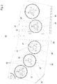
- FIG. 1 schematically illustrated round baler 10 includes a first housing part 12 which is supported by means of wheels 14 on a floor 15 and by means of a drawbar 16 to a towing vehicle, not shown, for. B. an agricultural tractor, can be connected.
- a crop picking and feeding device 18 which promotes cut crop through an insertion 19 into a baling chamber 20, wherein the first housing part 12 surrounds a front part of the baling chamber 20 .
- the second housing part 24 is in the open state, an opening 25 through which a pressed by the round baler 10 bales (not shown) can be set or unloaded or ejected.
- the pivotable second housing part 24 can be actuated (opened and closed) by means of servomotors (not shown) and thus constitutes an outlet flap for a bale pressed in the baling chamber 20.
- the round baler 10, formed with size-variable baling chamber 20, contains a plurality of mutually parallel extending press rollers in the form of press rollers 26 (exemplarily, only a few press rollers 26 were provided with the reference numeral "26"), the rolling axes 27 with closed second housing part 24 on a Arc are located, and at least some are driven.
- the press rollers 26 serve, in addition to a pressing and a shaping, in particular also a rotation generation or a rotation preservation of a in the pressing chamber 20th contained round bale (not shown).
- pressing rollers 26 'and 26 " which have a texture with a stronger engaging effect on the bale compared with the other press rollers 26.
- the round baler 10 is shown here as an example for illustrating the opening 25 with slightly open rear housing part 24. During a pressing process, however, this is closed.
- the round baler 10 comprises a bale wrapper 30 which is equipped with a supply roll (not shown) for wrapping material.
- the wrapping material may preferably be a net or foil.
- the bale wrapping device 30 comprises a wrapping material feed device 34, by means of which the wrapping material is fed from the supply roll through an insertion opening 35 into the baling chamber 20.
- the bale wrapping device 30 is also activated, and a wrapping process subsequent to the pressing process is initiated, whereby the wrapping material is wound around the round bale 20 by a continuous rotation of the round bale located in the baling chamber 20.
- the round bale is opened by opening the outlet flap (second housing part 24) through the opening 25 via a discharge ramp (not shown) on the floor 15. Then the ride on the round baler 10 is resumed and a new pressing operation begins.
- FIG. 2 The area around the press rollers 26 ', 26 "arranged on the underside of the round baler 10 on the rear side and on the front side of the opening 25 is shown in an enlarged detail in FIG FIG. 2 shown.
- the press rollers 26, 26 ', 26 “comprise a roller body 36, which is enclosed by a lateral surface 38.
- the roller body 36 is designed as a cylindrical tube profile and can be formed, for example, from a sheet metal material in a forming or rolling process 36 has axle hubs 40 at its end regions, which are fitted into the pipe profile and serve to support or support the rolling axles 27.
- Ribs 42 are arranged in each case on the lateral surfaces 38 and are formed by elevations which are formed on or in the lateral surface 38 along the rolling axes 27 of the roller body 36 over substantially the entire length of the roller body 36.
- the elevations can be formed for example by a sheet metal forming process in the sheet material of the roller body 36 or applied by welding on sheet metal strip on the lateral surface 38.
- FIGS. 1 and 2 illustrated embodiment shows a press roller 26 with example 8 on the circumference of the relevant roller body 36 evenly distributed ribs 42.
- the arranged on the underside of the round baler 10 back and front of the opening 25 press rollers 26 ', 26 "are, however, with a higher number of ribs 42nd provided, for example, with 16 ribs 42.
- the higher number of ribs 42 on the press rollers 26 'and 26 "represents a different texture to the other press rollers 26, in particular the surface texture of the press rollers 26', 26", whereby a stronger engagement effect a bale to be pressed is provided, that is, the press rollers 26 'and 26 "act with greater aggressiveness on the peripheral surface of a bale to be pressed, as the other press rollers 26.
- the stronger engaging effect also comes more to bear when the finished pressed bales are unloaded should and the weight of the bale s with opening rear housing part 24 increasingly on the press rollers 26 'and 26 "shifts. As in FIG.
- press rollers 26 must be equipped with 8 ribs 42, in particular not those who in addition to a bale-taking and shaping or pressing function also have other functions and, for example, in an insertion opening 35 for yarn or net material or in a Insertion channel 19 are arranged for crop. These may be equipped with fewer ribs 42 for technical reasons. However, this is not necessarily the case, so that in other embodiments, all other press rollers 26 are also occupied by 8 ribs. It should also be noted that the selection of 8 ribs 42 on the press rolls 26 and 16 ribs 42 on the press rolls 26 ', 26 "has been chosen here as an example, but more or fewer ribs 42 can be arranged overall.
- the press rollers 26, 26 ', 26 are driven in a known manner via a chain drive or belt drive (not shown), wherein the press rollers 26', 26" are additionally provided with a chain or belt drive circuit which increases the speed of the press rollers 26 '. , 26 "relative to the other press rollers 26.
- the arrangement for controlling a speed increase may comprise, for example, a sensor which supplies an opening signal to a control device, which in turn activates an actuating unit for switching the chain or belt drive circuit.
- the arrangement and design of a suitable chain or belt drive circuit is within the general knowledge of one of ordinary skill in drive technology for round balers and requires no further discussion in detail.
Landscapes
- Life Sciences & Earth Sciences (AREA)
- Environmental Sciences (AREA)
- Storage Of Harvested Produce (AREA)
- Harvesting Machines For Specific Crops (AREA)
Abstract
Description
- Die Erfindung betrifft eine landwirtschaftliche Rundballenpresse mit einer Ballenpresskammer aus mehreren angetriebenen und über einen Umfang der Ballenpresskammer angeordneten Pressrollen durch welche eine rotationserzeugende oder rotationserhaltene Eingriffswirkung auf einen in der Ballenpresskammer befindlichen Rundballen erzeugbar ist, wobei die Ballenpresskammer eine Öffnung aufweist, durch welche der gepresste Rundballen entladen werden kann.
- Landwirtschaftliche Rundballenpressen sind bekannt. Dabei wird in Rundballenpressen landwirtschaftliches Erntegut, beispielsweise Stroh, Gras oder Getreide zu einem Rundballen geformt und mit einem Umwicklungsmaterial, beispielsweise Netz, Folie oder Bindegarn, umwickelt. Derartige Rundballenpressen weisen eine Aufnahme- und Zuführeinrichtung für das zu pressende Erntegut auf, durch welche das Erntegut in eine Zuführöffnung einer Ballenpresskammer eingeführt wird. Die Ballenpresskammer umfasst mehrere in einem Kreis angeordnete Pressrollen, die sich über die Breite der Ballenpresskammer zwischen zwei Seitenwänden erstrecken und rotatorisch angetrieben sind. Zur besseren Mitnahme bzw. besseren Beförderung des in die Presskammer eingeführten Ernteguts sind die Pressrollen mit mehreren über den Umfang der Pressrollen verteilte Längsrippen oder Längsstege versehen, die, sich in radiale Richtung erstreckende, Erhebungen darstellen und sich über die Länge der Pressrolle erstecken. Die Rundballenpressen sind in der Regel mit einem zweigeteilten Gehäuse ausgebildet, wobei ein hinterer Teil hochgeklappt wird und eine Austrittsöffnung für einen gepressten Rundballen bildet. Das Öffnen erfolgt am Ende eines Pressvorgangs, wobei es insbesondere wichtig ist, dass der Rundballen bis zuletzt in einer steten Drehbewegung gehalten wird, nicht zuletzt auch um eine Netz- oder Garnbindung abzuschließen. Zum Entladen des Rundballens entsteht beim Öffnen des zweigeteilten Gehäuses ein Öffnungsspalt zwischen einem vorderen und einem hinteren Gehäuseteil, wodurch die Geometrie im Pressraum derart verändert wird, dass die Anordnung der Pressrollen zunehmend von einer Zylinderform abweicht da sich insbesondere der Abstand zwischen den unmittelbar an der Öffnung befindlichen Pressrollen vergrößert und sich die zuvor zylindrisch um den Rundballen angeordneten Pressrollen zunehmend von einer zylindrischen Umfangsfläche wegbewegen. Problematisch wirkt sich dies oftmals darin aus, dass eine rotationserzeugende oder rotationserhaltene Eingriffswirkung der Pressrollen auf den Rundballen zu früh abbrechen kann und der Rundballen nicht ausreichend lang in Rotation gehalten wird. Insbesondere bei trockenem Erntegut kann sich dieses Problem einstellen. Um dieses Problem zu beheben sind Versuche unternommen worden, die Eingriffsstärke der Pressrollen durch einen Zusammenschluss mehrerer Pressrollen mit einem Fördergurtsystem zu erhöhen. Dies kann sich jedoch auch negativ auf die Presseigenschaften bei feuchteren Erntebedingungen auswirken, weshalb spezielle Nachrüstsätze angeboten werden, die ein Nachrüsten des genannten Fördergurtsystems für trockene Erntebedingungen ermöglichen. Dies ist jedoch mit erheblichem Aufwand verbunden.
- Die der Erfindung zugrunde liegende Aufgabe wird darin gesehen, eine Pressrolle der eingangs genannten Art anzugeben, durch welche das oben genannte Problem behoben bzw. gemildert wird.
- Die Aufgabe wird erfindungsgemäß durch die Lehre des Patentanspruchs 1 gelöst. Weitere vorteilhafte Ausgestaltungen und Weiterbildungen der Erfindung gehen aus den Unteransprüchen hervor.
- Erfindungsgemäß ist eine landwirtschaftliche Rundballenpresse der eingangs genannten Art derart ausgebildet, dass an einer Unterseite der Ballenpresskammer wenigstens eine der unmittelbar rückseitig der Öffnung oder unmittelbar vorderseitig der Öffnung angeordneten Pressrollen mit einer zu den übrigen Pressrollen unterschiedlichen Drehzahl antreibbar ist. Dadurch wird es möglich, bei Beginn eines Entladeprozesses für einen fertig gepressten Rundballen, also bei sich öffnendem hinteren Gehäuseteil, die an einer Unterseite der Ballenpresskammer unmittelbar rückseitig der Öffnung und/oder unmittelbar vorderseitig der Öffnung angeordneten Pressrollen mit einer höheren Umdrehungszahl zu betreiben, um insgesamt eine stärkere Eingriffswirkung der betreffenden Pressrollen auf die Rundballenumfangsfläche zu erzeugen bzw. einer durch das Öffnen des hinteren Gehäuseteils hervorgerufenen abnehmenden Eingriffswirkung der übrigen Pressrollen entgegen zu wirken. Die stärkere Eingriffswirkung, bewirkt eine durch die Pressrollen auf die Rundballenumfangsfläche stärker ausgeübte Mitnahmewirkung, so dass der Rundballen ausreichend lang in Rotation gehalten wird. Auch wenn sich die übrigen Pressrollen zunehmend während des Öffnens des Gehäuses von der Rundballenoberfläche entfernen, können die unterhalb, unmittelbar an der Öffnung gelegenen Pressrollen, die Rotation des Rundballens aufrecht erhalten, da zudem das Gewicht des Rundballens mit zunehmendem Öffnungsspalt der Öffnung auch zunehmend auf den genannten beiden Pressrollen lastet und somit die stärkere Eingriffswirkung der beiden Pressrollen auch stärker zum Tragen kommt. In Folge kann eine durch die übrigen Pressrollen hervorgerufene abnehmende Rotationsantriebswirkung durch die beiden an der Öffnung gelegenen Pressrollen zunehmend kompensiert werden. Anhand der Zeichnung, die ein Ausführungsbeispiel der Erfindung zeigt, werden nachfolgend die Erfindung sowie weitere Vorteile und vorteilhafte Weiterbildungen und Ausgestaltungen der Erfindung näher beschrieben und erläutert.
- Es zeigt:
- Fig. 1
- eine schematische Seitenansicht einer landwirtschaftlichen Rundballenpresse mit Pressrollen und Öffnung zum Entladen eines gepressten Rundballens.
- Fig. 2
- einen vergrößerten Ausschnitt mit Pressrollen unmittelbar rückseitig und unmittelbar vorderseitig der Öffnung aus
Figur 1 . - Eine in der
Figur 1 schematisch dargestellte Rundballenpresse 10 umfasst einen ersten Gehäuseteil 12, der sich mittels Rädern 14 auf einem Boden 15 abstützt und mittels einer Deichsel 16 an ein nicht gezeigtes Zugfahrzeug, z. B. einen Ackerschlepper, anschließbar ist. - An einer in Vorwärtsfahrtrichtung vorderen unteren Seite des ersten Gehäuseteils 12 befindet sich in bekannter Weise eine Aufnahme- und Zuführeinrichtung 18 für Erntegut, die geschnittenes Erntegut durch einen Einführkanal 19 in eine Ballenpresskammer 20 fördert, wobei der erste Gehäuseteil 12 einen vorderen Teil der Ballenpresskammer 20 umgibt. An dem rückwärtigen oberen Eckbereich des ersten Gehäuseteils 12 befindet sich ein Lager 22 für ein schwenkbares zweites Gehäuseteil 24, das einen hinteren Teil der Ballenpresskammer 20 umgibt. Das zweite Gehäuseteil 24 gibt im geöffneten Zustand eine Öffnung 25 frei, durch welchen ein von der Rundballenpresse 10 gepresster Ballen (nicht gezeigt) abgesetzt bzw. entladen oder ausgeworfen werden kann. Das schwenkbare zweite Gehäuseteil 24 kann mittels Stellmotoren (nicht gezeigt) betätigt werden (geöffnet und geschlossen werden) und stellt somit eine Auslassklappe für einen in der Ballenpresskammer 20 gepressten Ballen dar.
- Die Rundballenpresse 10, mit größenunveränderlicher Ballenpresskammer 20 ausgebildet, enthält eine Vielzahl zueinander parallel verlaufender Pressrollen in Form von Pressrollen 26 (exemplarisch wurden hier nur einige wenige Pressrollen 26 mit dem Bezugszeichen "26" versehen), deren Rollachsen 27 bei geschlossenem zweiten Gehäuseteil 24 auf einem Kreisbogen gelegen sind, und von denen wenigstens einige angetrieben sind. Die Pressrollen 26 dienen, neben einem Pressen und einer Formgebung, insbesondere auch einer Rotationserzeugung oder einer Rotationserhaltung eines in der Presskammer 20 enthaltenen Rundballens (nicht gezeigt). Unmittelbar rückseitig und vorderseitig der Öffnung 25, zum Entladen eines gepressten Ballens, sind Pressrollen 26' und 26" angeordnet, die gegenüber den übrigen Pressrollen 26 eine Beschaffenheit mit einer stärkeren Eingriffswirkung auf den Ballen aufweisen. Die Rundballenpresse 10 ist hier exemplarisch zur Darstellung der Öffnung 25 mit leicht geöffnetem hinterem Gehäuseteil 24 abgebildet. Während eines Pressvorgangs ist dieser jedoch geschlossen.
- Ferner umfasst die Rundballenpresse 10 eine Ballenwickeleinrichtung 30, die mit einer Vorratsrolle (nicht gezeigt) für Umwicklungsmaterial bestückt ist. Als Umwicklungsmaterial kann vorzugsweise ein Netz oder auch Folie eingesetzt werden. Die Ballenwickeleinrichtung 30 umfasst eine Zuführeinrichtung 34 für das Umwicklungsmaterial, mittels welcher das Umwicklungsmaterial von der Vorratsrolle durch eine Einführöffnung 35 in die Ballenpresskammer 20 geführt wird.
- Nachdem der eigentliche Pressvorgang, also die Erntegutaufnahme und Bildung eines Rundballens durch die Pressrollen 26, 26', 26" abgeschlossen ist, wird eine Fahrt über den Boden 15 unterbrochen, da die Rundballenpresse 10 mit dem Rundballen gefüllt ist und kein weiteres Erntegut mehr in die Ballenpresskammer 20 aufgenommen werden soll bzw. kann. Zu dieser Zeit wird auch die Ballenwickeleinrichtung 30 aktiviert, und ein sich dem Pressvorgang anschließender Umwicklungsvorgang eingeleitet. Dabei wird durch eine anhaltende Drehung des sich in der Ballenpresskammer 20 befindlichen Rundballens das Umwicklungsmaterial um den Rundballen 20 gewickelt. Nachdem ein Umwicklungsvorgang abgeschlossen ist wird der Rundballen mittels Öffnen der Auslassklappe (zweiter Gehäuseteil 24) durch die Öffnung 25 über einer Entladerampe (nicht gezeigt) auf dem Boden 15 abgelassen. Sodann wird die Fahrt mit der Rundballenpresse 10 wieder aufgenommen und ein neuer Pressvorgang beginnt.
- Der Bereich um die auf der Unterseite der Rundballenpresse 10 rückseitig und vorderseitig der Öffnung 25 angeordneten Pressrollen 26', 26" ist in einem vergrößerten Ausschnitt in
Figur 2 dargestellt. - Wie in
Figur 2 dargestellt ist, umfassen die Pressrollen 26, 26', 26" einen Rollenkörper 36, der von einer Mantelfläche 38 umschlossen wird. Der Rollenkörper 36 ist als zylindrisches Rohrprofil ausgebildet und kann beispielsweise aus einem Blechmaterial in einem Umformverfahren bzw. Walzverfahren geformt sein. Der Rollenkörper 36 weist an seinen Endbereichen Achsnaben 40 auf, die in das Rohrprofil eingepasst sind und der Halterung bzw. Lagerung der Rollachsen 27 dienen. - Jeweils auf den Mantelflächen 38 sind Rippen 42 angeordnet, die durch Erhebungen gebildet werden, die auf bzw. in der Mantelfläche 38 entlang der Rollachsen 27 des Rollenkörpers 36 über im Wesentlichen die gesamte Länge des Rollenkörpers 36 ausgebildet sind. Die Erhebungen können beispielsweise durch ein Blechumformverfahren in das Blechmaterial des Rollenkörpers 36 eingeformt oder auch durch Aufschweißungen von Blechstreifen auf die Mantelfläche 38 aufgebracht werden.
- Das in den
Figuren 1 und2 dargestellte Ausführungsbeispiel zeigt eine Pressrolle 26 mit beispielhaft 8 auf dem Umfang des diesbezüglichen Rollenkörpers 36 gleichmäßig verteilten Rippen 42. Die auf der Unterseite der Rundballenpresse 10 rückseitig und vorderseitig der Öffnung 25 angeordneten Pressrollen 26', 26" sind hingegen mit einer höheren Anzahl von Rippen 42 versehen, hier beispielhaft mit 16 Rippen 42. Die höhere Anzahl von Rippen 42 an den Pressrollen 26' und 26" stellt eine zu den übrigen Pressrollen 26 verschiedene Beschaffenheit, insbesondere der Oberflächenbeschaffenheit der Pressrollen 26', 26" dar, wodurch eine stärkere Eingriffswirkung auf einen zu pressenden Ballen geschaffen wird, d.h. die Pressrollen 26' und 26" wirken mit größerer Aggressivität auf die Umfangsfläche eines zu pressenden Ballens ein, als die übrigen Pressrollen 26. Die stärkere Eingriffswirkung kommt zudem verstärkt zum Tragen, wenn der fertig gepresste Ballen entladen werden soll und sich das Gewicht des Ballens bei sich öffnendem hinteren Gehäuseteil 24 zunehmend auf die Pressrollen 26' und 26" verlagert. Wie inFigur 1 zu sehen ist, müssen nicht alle Pressrollen 26 mit 8 Rippen 42 bestückt sein, insbesondere nicht diejenigen, die neben einer Ballenmitnahme-und Formgebungs- bzw. Pressfunktion auch noch weitere Funktionen innehaben und beispielsweise in einer Einführöffnung 35 für Garn- oder Netzmaterial oder in einem Einführkanal 19 für Erntegut angeordnet sind. Diese können aus technischen Gründen auch mit weniger Rippen 42 bestückt sein. Dies ist jedoch nicht zwingend der Fall, so dass in anderen Ausführungsformen durchaus auch alle übrigen Pressrollen 26 mit 8 Rippen besetzt sind. Ferner sei darauf hingewiesen, dass die Auswahl von 8 Rippen 42 an den Pressrollen 26 und 16 Rippen 42 an den Pressrollen 26', 26" hier als Beispiel gewählt wurde. Es sind aber insgesamt auch mehr oder weniger Rippen 42 anordbar. - Die Pressrollen 26, 26', 26" sind in bekannter Weise über einen Kettentrieb oder Riementrieb (nicht gezeigt) angetrieben, wobei die Pressrollen 26', 26" zusätzlich mit einer Ketten- bzw. Riementriebschaltung versehen sind, die eine Drehzahlerhöhung der Pressrollen 26', 26" gegenüber den übrigen Pressrollen 26 ermöglicht. Sobald sich die Auslassklappe, also der hintere Gehäuseteil 24 zum Auswerfen des Ballens, öffnet, wird die Drehzahl der Pressrollen 26', 26" erhöht und dadurch eine abnehmende Eingriffswirkung der übrigen Pressrollen 26 kompensiert. Die Anordnung für eine Steuerung einer Drehzahlerhöhung kann beispielsweise einen Sensor umfassen, der ein Öffnungssignal an eine Steuereinrichtung liefert, welche wiederum eine Stelleinheit zum Schalten der Ketten- bzw. Riementriebschaltung aktiviert. Die Anordnung und Ausbildung einer geeigneten Ketten- bzw. Riementriebschaltung liegt im Bereich des Allgemeinwissens eines Fachmanns für Antriebstechnik für Rundballenpressen und erfordert keine weitere Erörterung im Detail.
Claims (1)
- Landwirtschaftliche Rundballenpresse (10) mit einer Ballenpresskammer (20) aus mehreren angetriebenen und über einen Umfang der Ballenpresskammer (20) angeordneten Pressrollen (26, 26', 26") durch welche eine rotationserzeugende oder rotationserhaltene Eingriffswirkung auf einen in der Ballenpresskammer (20) befindlichen Rundballen erzeugbar ist, wobei die Ballenpresskammer (20) eine Öffnung (25) aufweist, durch welche der gepresste Rundballen entladen werden kann, dadurch gekennzeichnet, dass an einer Unterseite der Ballenpresskammer (10) wenigstens eine der unmittelbar rückseitig der Öffnung (25) oder unmittelbar vorderseitig der Öffnung angeordneten Pressrollen (26', 26") mit einer zu den übrigen Pressrollen (26) unterschiedlichen Drehzahl antreibbar ist.
Priority Applications (1)
| Application Number | Priority Date | Filing Date | Title |
|---|---|---|---|
| PL16168615T PL3103324T3 (pl) | 2015-05-11 | 2016-05-06 | Prasa do bel okrągłych |
Applications Claiming Priority (1)
| Application Number | Priority Date | Filing Date | Title |
|---|---|---|---|
| DE102015208674.7A DE102015208674A1 (de) | 2015-05-11 | 2015-05-11 | Landwirtschaftliche Rundballenpresse |
Publications (2)
| Publication Number | Publication Date |
|---|---|
| EP3103324A1 true EP3103324A1 (de) | 2016-12-14 |
| EP3103324B1 EP3103324B1 (de) | 2018-11-21 |
Family
ID=55919720
Family Applications (1)
| Application Number | Title | Priority Date | Filing Date |
|---|---|---|---|
| EP16168615.9A Active EP3103324B1 (de) | 2015-05-11 | 2016-05-06 | Landwirtschaftiche rundballenpresse |
Country Status (3)
| Country | Link |
|---|---|
| EP (1) | EP3103324B1 (de) |
| DE (1) | DE102015208674A1 (de) |
| PL (1) | PL3103324T3 (de) |
Citations (6)
| Publication number | Priority date | Publication date | Assignee | Title |
|---|---|---|---|---|
| DE2524434A1 (de) * | 1974-06-03 | 1975-12-11 | Sperry Rand Corp | Heurollen-formmaschine |
| US4619106A (en) | 1983-12-01 | 1986-10-28 | C. Van Der Lely N.V. | Balers |
| EP1466520A1 (de) | 2003-04-08 | 2004-10-13 | Welger Maschinenfabrik GmbH | Rundballenpresse |
| EP1927279A1 (de) * | 2006-11-28 | 2008-06-04 | Deere & Company | Rolle und landwirtschaftlich nutzbare Maschine |
| DE102011006823A1 (de) | 2010-04-29 | 2011-11-03 | Deere & Company | Rundballenpresse mit elektrisch angetriebenen Ballenpressmitteln |
| WO2014129890A1 (en) | 2013-02-22 | 2014-08-28 | Forage Innovations B.V. | Baling chamber with pivotally mounted conveying unit |
Family Cites Families (1)
| Publication number | Priority date | Publication date | Assignee | Title |
|---|---|---|---|---|
| FR2663191A1 (fr) * | 1990-06-18 | 1991-12-20 | Inst Cercetare Stiintifica | Ramasseuse-presse pour residus vegetaux de paille et de bois. |
-
2015
- 2015-05-11 DE DE102015208674.7A patent/DE102015208674A1/de not_active Ceased
-
2016
- 2016-05-06 PL PL16168615T patent/PL3103324T3/pl unknown
- 2016-05-06 EP EP16168615.9A patent/EP3103324B1/de active Active
Patent Citations (6)
| Publication number | Priority date | Publication date | Assignee | Title |
|---|---|---|---|---|
| DE2524434A1 (de) * | 1974-06-03 | 1975-12-11 | Sperry Rand Corp | Heurollen-formmaschine |
| US4619106A (en) | 1983-12-01 | 1986-10-28 | C. Van Der Lely N.V. | Balers |
| EP1466520A1 (de) | 2003-04-08 | 2004-10-13 | Welger Maschinenfabrik GmbH | Rundballenpresse |
| EP1927279A1 (de) * | 2006-11-28 | 2008-06-04 | Deere & Company | Rolle und landwirtschaftlich nutzbare Maschine |
| DE102011006823A1 (de) | 2010-04-29 | 2011-11-03 | Deere & Company | Rundballenpresse mit elektrisch angetriebenen Ballenpressmitteln |
| WO2014129890A1 (en) | 2013-02-22 | 2014-08-28 | Forage Innovations B.V. | Baling chamber with pivotally mounted conveying unit |
Also Published As
| Publication number | Publication date |
|---|---|
| PL3103324T3 (pl) | 2019-05-31 |
| EP3103324B1 (de) | 2018-11-21 |
| DE102015208674A1 (de) | 2016-11-17 |
Similar Documents
| Publication | Publication Date | Title |
|---|---|---|
| DE60218400T2 (de) | Rundballenpresse | |
| DE69522816T2 (de) | Kombinierte presse- und wickelgerät für zylindrische körper | |
| EP2893799A1 (de) | Landwirtschaftliche Rundballenpresse und Verfahren | |
| DE2530249A1 (de) | Wickelballenpresse | |
| EP2939523A1 (de) | Ballenwickeleinrichtung und rundballenpresse mit einer solchen | |
| EP2962545B1 (de) | Landwirtschaftliche rundballenpresse mit einer ballenpressrolle | |
| EP1424001A1 (de) | Ballenpresse | |
| EP3421386A1 (de) | Hüllmaterial für eine ballenpresse und verfahren | |
| EP2984922A1 (de) | Ballenwickeleinrichtung | |
| EP3421387B1 (de) | Hüllmaterial für eine ballenpresse | |
| DE102007031211B4 (de) | Ballenpresse | |
| DE102012007895A1 (de) | Verfahren zur Herstellung einer Schaltwelle | |
| EP3097770B1 (de) | Landwirtschaftliche rundballenpresse | |
| EP3103324B1 (de) | Landwirtschaftiche rundballenpresse | |
| EP3560323B1 (de) | Landwirtschaftliche rundballenpresse und verfahren zum betrieb einer landwirtschaftlichen rundballenpresse | |
| DE4312991A1 (de) | Verfahren und Presse zum Bilden quaderförmiger Preßballen aus landwirtschaftlichem Erntegut | |
| EP2556743B1 (de) | Landwirtschaftliche Rundballenpresse | |
| EP3106019B1 (de) | Rundballenpresse und zuführwalze für wickelmaterial | |
| EP3760031B1 (de) | Rundballenpresse und verfahren zum betrieb einer rundballenpresse | |
| EP3414991A1 (de) | Umhüllungseinrichtung und rundballenpresse | |
| EP3085222A1 (de) | Landwirtschaftliche rundballenpresse | |
| EP4282248A1 (de) | Rundballenpresse | |
| DE102015214557A1 (de) | Landwirtschaftliche Rundballenpresse und Verfahren zum Betreiben einer solchen | |
| DE1901354A1 (de) | Verfahren zum Verarbeiten von landwirtschaftlichem Erntegut,wie Heu und aehnlichen Futterstoffen | |
| EP3130216A1 (de) | Ballenpresse und leiteinrichtung |
Legal Events
| Date | Code | Title | Description |
|---|---|---|---|
| PUAI | Public reference made under article 153(3) epc to a published international application that has entered the european phase |
Free format text: ORIGINAL CODE: 0009012 |
|
| STAA | Information on the status of an ep patent application or granted ep patent |
Free format text: STATUS: THE APPLICATION HAS BEEN PUBLISHED |
|
| AK | Designated contracting states |
Kind code of ref document: A1 Designated state(s): AL AT BE BG CH CY CZ DE DK EE ES FI FR GB GR HR HU IE IS IT LI LT LU LV MC MK MT NL NO PL PT RO RS SE SI SK SM TR |
|
| AX | Request for extension of the european patent |
Extension state: BA ME |
|
| TPAC | Observations filed by third parties |
Free format text: ORIGINAL CODE: EPIDOSNTIPA |
|
| STAA | Information on the status of an ep patent application or granted ep patent |
Free format text: STATUS: REQUEST FOR EXAMINATION WAS MADE |
|
| 17P | Request for examination filed |
Effective date: 20170614 |
|
| RBV | Designated contracting states (corrected) |
Designated state(s): AL AT BE BG CH CY CZ DE DK EE ES FI FR GB GR HR HU IE IS IT LI LT LU LV MC MK MT NL NO PL PT RO RS SE SI SK SM TR |
|
| STAA | Information on the status of an ep patent application or granted ep patent |
Free format text: STATUS: EXAMINATION IS IN PROGRESS |
|
| 17Q | First examination report despatched |
Effective date: 20170907 |
|
| GRAP | Despatch of communication of intention to grant a patent |
Free format text: ORIGINAL CODE: EPIDOSNIGR1 |
|
| STAA | Information on the status of an ep patent application or granted ep patent |
Free format text: STATUS: GRANT OF PATENT IS INTENDED |
|
| INTG | Intention to grant announced |
Effective date: 20180604 |
|
| GRAS | Grant fee paid |
Free format text: ORIGINAL CODE: EPIDOSNIGR3 |
|
| GRAA | (expected) grant |
Free format text: ORIGINAL CODE: 0009210 |
|
| STAA | Information on the status of an ep patent application or granted ep patent |
Free format text: STATUS: THE PATENT HAS BEEN GRANTED |
|
| AK | Designated contracting states |
Kind code of ref document: B1 Designated state(s): AL AT BE BG CH CY CZ DE DK EE ES FI FR GB GR HR HU IE IS IT LI LT LU LV MC MK MT NL NO PL PT RO RS SE SI SK SM TR |
|
| REG | Reference to a national code |
Ref country code: CH Ref legal event code: EP |
|
| REG | Reference to a national code |
Ref country code: IE Ref legal event code: FG4D Free format text: LANGUAGE OF EP DOCUMENT: GERMAN |
|
| REG | Reference to a national code |
Ref country code: AT Ref legal event code: REF Ref document number: 1066416 Country of ref document: AT Kind code of ref document: T Effective date: 20181215 |
|
| REG | Reference to a national code |
Ref country code: DE Ref legal event code: R096 Ref document number: 502016002546 Country of ref document: DE |
|
| REG | Reference to a national code |
Ref country code: NL Ref legal event code: MP Effective date: 20181121 |
|
| PG25 | Lapsed in a contracting state [announced via postgrant information from national office to epo] |
Ref country code: ES Free format text: LAPSE BECAUSE OF FAILURE TO SUBMIT A TRANSLATION OF THE DESCRIPTION OR TO PAY THE FEE WITHIN THE PRESCRIBED TIME-LIMIT Effective date: 20181121 Ref country code: IS Free format text: LAPSE BECAUSE OF FAILURE TO SUBMIT A TRANSLATION OF THE DESCRIPTION OR TO PAY THE FEE WITHIN THE PRESCRIBED TIME-LIMIT Effective date: 20190321 Ref country code: LT Free format text: LAPSE BECAUSE OF FAILURE TO SUBMIT A TRANSLATION OF THE DESCRIPTION OR TO PAY THE FEE WITHIN THE PRESCRIBED TIME-LIMIT Effective date: 20181121 Ref country code: NO Free format text: LAPSE BECAUSE OF FAILURE TO SUBMIT A TRANSLATION OF THE DESCRIPTION OR TO PAY THE FEE WITHIN THE PRESCRIBED TIME-LIMIT Effective date: 20190221 Ref country code: BG Free format text: LAPSE BECAUSE OF FAILURE TO SUBMIT A TRANSLATION OF THE DESCRIPTION OR TO PAY THE FEE WITHIN THE PRESCRIBED TIME-LIMIT Effective date: 20190221 Ref country code: HR Free format text: LAPSE BECAUSE OF FAILURE TO SUBMIT A TRANSLATION OF THE DESCRIPTION OR TO PAY THE FEE WITHIN THE PRESCRIBED TIME-LIMIT Effective date: 20181121 Ref country code: LV Free format text: LAPSE BECAUSE OF FAILURE TO SUBMIT A TRANSLATION OF THE DESCRIPTION OR TO PAY THE FEE WITHIN THE PRESCRIBED TIME-LIMIT Effective date: 20181121 Ref country code: FI Free format text: LAPSE BECAUSE OF FAILURE TO SUBMIT A TRANSLATION OF THE DESCRIPTION OR TO PAY THE FEE WITHIN THE PRESCRIBED TIME-LIMIT Effective date: 20181121 |
|
| PG25 | Lapsed in a contracting state [announced via postgrant information from national office to epo] |
Ref country code: RS Free format text: LAPSE BECAUSE OF FAILURE TO SUBMIT A TRANSLATION OF THE DESCRIPTION OR TO PAY THE FEE WITHIN THE PRESCRIBED TIME-LIMIT Effective date: 20181121 Ref country code: SE Free format text: LAPSE BECAUSE OF FAILURE TO SUBMIT A TRANSLATION OF THE DESCRIPTION OR TO PAY THE FEE WITHIN THE PRESCRIBED TIME-LIMIT Effective date: 20181121 Ref country code: AL Free format text: LAPSE BECAUSE OF FAILURE TO SUBMIT A TRANSLATION OF THE DESCRIPTION OR TO PAY THE FEE WITHIN THE PRESCRIBED TIME-LIMIT Effective date: 20181121 Ref country code: GR Free format text: LAPSE BECAUSE OF FAILURE TO SUBMIT A TRANSLATION OF THE DESCRIPTION OR TO PAY THE FEE WITHIN THE PRESCRIBED TIME-LIMIT Effective date: 20190222 Ref country code: NL Free format text: LAPSE BECAUSE OF FAILURE TO SUBMIT A TRANSLATION OF THE DESCRIPTION OR TO PAY THE FEE WITHIN THE PRESCRIBED TIME-LIMIT Effective date: 20181121 Ref country code: PT Free format text: LAPSE BECAUSE OF FAILURE TO SUBMIT A TRANSLATION OF THE DESCRIPTION OR TO PAY THE FEE WITHIN THE PRESCRIBED TIME-LIMIT Effective date: 20190321 |
|
| PG25 | Lapsed in a contracting state [announced via postgrant information from national office to epo] |
Ref country code: IT Free format text: LAPSE BECAUSE OF FAILURE TO SUBMIT A TRANSLATION OF THE DESCRIPTION OR TO PAY THE FEE WITHIN THE PRESCRIBED TIME-LIMIT Effective date: 20181121 Ref country code: DK Free format text: LAPSE BECAUSE OF FAILURE TO SUBMIT A TRANSLATION OF THE DESCRIPTION OR TO PAY THE FEE WITHIN THE PRESCRIBED TIME-LIMIT Effective date: 20181121 Ref country code: CZ Free format text: LAPSE BECAUSE OF FAILURE TO SUBMIT A TRANSLATION OF THE DESCRIPTION OR TO PAY THE FEE WITHIN THE PRESCRIBED TIME-LIMIT Effective date: 20181121 |
|
| REG | Reference to a national code |
Ref country code: DE Ref legal event code: R097 Ref document number: 502016002546 Country of ref document: DE |
|
| PG25 | Lapsed in a contracting state [announced via postgrant information from national office to epo] |
Ref country code: SM Free format text: LAPSE BECAUSE OF FAILURE TO SUBMIT A TRANSLATION OF THE DESCRIPTION OR TO PAY THE FEE WITHIN THE PRESCRIBED TIME-LIMIT Effective date: 20181121 Ref country code: EE Free format text: LAPSE BECAUSE OF FAILURE TO SUBMIT A TRANSLATION OF THE DESCRIPTION OR TO PAY THE FEE WITHIN THE PRESCRIBED TIME-LIMIT Effective date: 20181121 Ref country code: RO Free format text: LAPSE BECAUSE OF FAILURE TO SUBMIT A TRANSLATION OF THE DESCRIPTION OR TO PAY THE FEE WITHIN THE PRESCRIBED TIME-LIMIT Effective date: 20181121 Ref country code: SK Free format text: LAPSE BECAUSE OF FAILURE TO SUBMIT A TRANSLATION OF THE DESCRIPTION OR TO PAY THE FEE WITHIN THE PRESCRIBED TIME-LIMIT Effective date: 20181121 |
|
| PLBE | No opposition filed within time limit |
Free format text: ORIGINAL CODE: 0009261 |
|
| STAA | Information on the status of an ep patent application or granted ep patent |
Free format text: STATUS: NO OPPOSITION FILED WITHIN TIME LIMIT |
|
| 26N | No opposition filed |
Effective date: 20190822 |
|
| PG25 | Lapsed in a contracting state [announced via postgrant information from national office to epo] |
Ref country code: SI Free format text: LAPSE BECAUSE OF FAILURE TO SUBMIT A TRANSLATION OF THE DESCRIPTION OR TO PAY THE FEE WITHIN THE PRESCRIBED TIME-LIMIT Effective date: 20181121 |
|
| REG | Reference to a national code |
Ref country code: CH Ref legal event code: PL |
|
| PG25 | Lapsed in a contracting state [announced via postgrant information from national office to epo] |
Ref country code: LI Free format text: LAPSE BECAUSE OF NON-PAYMENT OF DUE FEES Effective date: 20190531 Ref country code: CH Free format text: LAPSE BECAUSE OF NON-PAYMENT OF DUE FEES Effective date: 20190531 Ref country code: MC Free format text: LAPSE BECAUSE OF FAILURE TO SUBMIT A TRANSLATION OF THE DESCRIPTION OR TO PAY THE FEE WITHIN THE PRESCRIBED TIME-LIMIT Effective date: 20181121 |
|
| REG | Reference to a national code |
Ref country code: BE Ref legal event code: MM Effective date: 20190531 |
|
| PG25 | Lapsed in a contracting state [announced via postgrant information from national office to epo] |
Ref country code: LU Free format text: LAPSE BECAUSE OF NON-PAYMENT OF DUE FEES Effective date: 20190506 |
|
| PG25 | Lapsed in a contracting state [announced via postgrant information from national office to epo] |
Ref country code: TR Free format text: LAPSE BECAUSE OF FAILURE TO SUBMIT A TRANSLATION OF THE DESCRIPTION OR TO PAY THE FEE WITHIN THE PRESCRIBED TIME-LIMIT Effective date: 20181121 |
|
| PG25 | Lapsed in a contracting state [announced via postgrant information from national office to epo] |
Ref country code: BE Free format text: LAPSE BECAUSE OF NON-PAYMENT OF DUE FEES Effective date: 20190531 |
|
| PG25 | Lapsed in a contracting state [announced via postgrant information from national office to epo] |
Ref country code: FR Free format text: LAPSE BECAUSE OF NON-PAYMENT OF DUE FEES Effective date: 20190531 |
|
| GBPC | Gb: european patent ceased through non-payment of renewal fee |
Effective date: 20200506 |
|
| PG25 | Lapsed in a contracting state [announced via postgrant information from national office to epo] |
Ref country code: GB Free format text: LAPSE BECAUSE OF NON-PAYMENT OF DUE FEES Effective date: 20200506 |
|
| PG25 | Lapsed in a contracting state [announced via postgrant information from national office to epo] |
Ref country code: CY Free format text: LAPSE BECAUSE OF FAILURE TO SUBMIT A TRANSLATION OF THE DESCRIPTION OR TO PAY THE FEE WITHIN THE PRESCRIBED TIME-LIMIT Effective date: 20181121 |
|
| PG25 | Lapsed in a contracting state [announced via postgrant information from national office to epo] |
Ref country code: HU Free format text: LAPSE BECAUSE OF FAILURE TO SUBMIT A TRANSLATION OF THE DESCRIPTION OR TO PAY THE FEE WITHIN THE PRESCRIBED TIME-LIMIT; INVALID AB INITIO Effective date: 20160506 Ref country code: MT Free format text: LAPSE BECAUSE OF FAILURE TO SUBMIT A TRANSLATION OF THE DESCRIPTION OR TO PAY THE FEE WITHIN THE PRESCRIBED TIME-LIMIT Effective date: 20181121 |
|
| PG25 | Lapsed in a contracting state [announced via postgrant information from national office to epo] |
Ref country code: MK Free format text: LAPSE BECAUSE OF FAILURE TO SUBMIT A TRANSLATION OF THE DESCRIPTION OR TO PAY THE FEE WITHIN THE PRESCRIBED TIME-LIMIT Effective date: 20181121 |
|
| REG | Reference to a national code |
Ref country code: AT Ref legal event code: MM01 Ref document number: 1066416 Country of ref document: AT Kind code of ref document: T Effective date: 20210506 |
|
| PG25 | Lapsed in a contracting state [announced via postgrant information from national office to epo] |
Ref country code: AT Free format text: LAPSE BECAUSE OF NON-PAYMENT OF DUE FEES Effective date: 20210506 |
|
| PGFP | Annual fee paid to national office [announced via postgrant information from national office to epo] |
Ref country code: PL Payment date: 20240419 Year of fee payment: 9 |
|
| PGFP | Annual fee paid to national office [announced via postgrant information from national office to epo] |
Ref country code: DE Payment date: 20250423 Year of fee payment: 10 |
|
| PGFP | Annual fee paid to national office [announced via postgrant information from national office to epo] |
Ref country code: IE Payment date: 20250527 Year of fee payment: 10 |